JP3645560B2 - Cleaning unit - Google Patents
Cleaning unit Download PDFInfo
- Publication number
- JP3645560B2 JP3645560B2 JP2003344705A JP2003344705A JP3645560B2 JP 3645560 B2 JP3645560 B2 JP 3645560B2 JP 2003344705 A JP2003344705 A JP 2003344705A JP 2003344705 A JP2003344705 A JP 2003344705A JP 3645560 B2 JP3645560 B2 JP 3645560B2
- Authority
- JP
- Japan
- Prior art keywords
- toner
- paper
- sheet
- outer peripheral
- fall prevention
- Prior art date
- Legal status (The legal status is an assumption and is not a legal conclusion. Google has not performed a legal analysis and makes no representation as to the accuracy of the status listed.)
- Expired - Fee Related
Links
Images


Description
この発明は、像担持体の外周部に形成されたトナー像を転写して用紙に画像を形成する画像形成装置において適用され、像担持体の外周部に付着する残留トナー及び紙粉を除去するクリーニングユニットに関する。 The present invention is applied to an image forming apparatus that transfers a toner image formed on an outer periphery of an image carrier to form an image on a sheet, and removes residual toner and paper dust attached to the outer periphery of the image carrier. Regarding the cleaning unit.
従来より画像形成装置における画像形成の際に用紙(OHP等の記録媒体を含む。)を画像形成部に搬送するには、装置本体の内部に配置された給紙カセットから画像形成部に給紙する給紙方式と装置本体の外部に配置された手差給紙トレイから画像形成部に給紙する給紙方式との2方式がある。 Conventionally, in order to transport paper (including recording media such as OHP) to an image forming unit during image formation in an image forming apparatus, paper is fed to the image forming unit from a paper feed cassette disposed inside the apparatus main body. There are two methods: a paper feeding method that feeds the image forming unit from a manual paper feed tray disposed outside the apparatus main body.
上記給紙カセット及び手差給紙トレイに収納された用紙は、画像形成時に1枚ずつ選択的に給紙された後に用紙搬送路を経て画像形成部に搬送されて画像形成される。ここで、用紙を1枚ずつ給紙する際、用紙は捌き部材によって1枚ずつに捌かれる。そのため、用紙と捌き部材との摩擦等により用紙中に含まれる紙粉であるタルク部材(漂白剤、増量剤等々。主成分はSi O2 と類推される。)が用紙から分離する。この紙粉は、搬送ローラ等の摩擦等によって帯電することで用紙搬送路上に配置された各搬送ローラや画像形成部に備えられる感光体(像担持体)の外周部に付着且つ堆積し、画像品位の低下を招来していた。 The sheets stored in the sheet feeding cassette and the manual sheet feeding tray are selectively fed one by one at the time of image formation, and then conveyed to an image forming unit through a sheet conveying path to form an image. Here, when the sheets are fed one by one, the sheets are fed one by one by the separating member. Therefore, a talc member (a bleaching agent, an extender, etc., whose main component is analogized with S i O 2 ), which is a paper powder contained in the paper, is separated from the paper by friction between the paper and the rolling member. This paper dust is charged by friction or the like of the transport roller and the like, and adheres and accumulates on the outer periphery of each transport roller arranged on the paper transport path and the photosensitive member (image carrier) provided in the image forming unit. It has caused a decline in quality.
例えば、図6に示すように、感光体31の外周部に付着する紙粉Pは、感光体31の外周部に形成されたトナー像の用紙への転写後に、クリーニングユニット35によって感光体31の外周部に残留している残留トナーとともに除去される。クリーニングユニット35は、感光体31の外周部に形成されたトナー像を用紙に転写する位置よりも図6の矢印に示す感光体31の回転方向の下流側における感光体31の外周部に配置され、開口部35aの形成されたユニット本体に、クリーニングブレード35c及びトナー落下防止シート35eを備えている。
For example, as shown in FIG. 6, the paper dust P adhering to the outer peripheral portion of the
開口部35aは、掻き落とされた残留トナー等をクリーニングユニット35内部に回収する。クリーニングブレード35cは、一部が感光体31の外周部に接触し、感光体31の外周部に付着する残留トナー及び紙粉Pを掻き落とす。トナー落下防止シート35eは、掻き落とした残留トナー等が開口部35aから回収されず、用紙搬送路等に落下するのを防止する。
The opening 35a collects the residual toner and the like scraped off in the
この時、流動性の良いトナーは、感光体31の外周部に接触するクリーニングブレード35c等の部材から剥離して開口部35aから回収されるが、紙粉Pは流動性が悪いために剥離し難く、感光体31の外周部に接触するクリーニングブレード35c等の部材に堆積してしまう。
At this time, the toner with good fluidity is separated from the member such as the
また紙粉Pは、所定量が堆積されると堆積していた部材から剥離し、一部は開口部35aから回収されるが、大部分は感光体31の外周部に再付着して感光体31の外周部に配置される現像槽等に混入してしまう。紙粉Pが現像槽に混入すると、トナーと紙粉(Si O2 )の帯電特性の違いから、トナーの正常な帯電を阻害し、未帯電トナーの発生を助長し、画像品位の低下及び画像呆けが発生する。特に、図6に示すように、クリーニングブレード35cから剥離した紙粉Pは、落下してトナー落下防止シート35eに堆積し易いので、堆積した紙粉Pによって開口部35aの開口面積が狭くなって残留トナー及び紙粉Pの回収能力が低下してまう。また、トナー落下防止シート35eは、クリーニングブレード35cよりも感光体31の回転方向の上流側に位置するため、感光体31の外周部との接触部分及びその周辺に紙粉Pが堆積し易いので、堆積した紙粉Pが剥離して用紙搬送路やトナー像の転写された用紙に落下して画像品位が低下してしまう。
Further, when a predetermined amount of paper dust P is deposited, the paper dust P is peeled off from the deposited member, and a part of the paper dust P is collected from the opening 35a. It will mix in the developing tank etc. which are arrange | positioned at the outer peripheral part of 31. When the paper dust P is mixed in the developing tank, the difference in charging characteristics between the toner and the paper dust (S i O 2 ) inhibits the normal charging of the toner, promotes the generation of uncharged toner, reduces the image quality, Image blur occurs. In particular, as shown in FIG. 6, the paper dust P peeled off from the
そこで、近年の画像形成装置には、フィードローラ及びフィードローラに当接する捌き部材表面の動摩擦係数よりも大きい動摩擦係数を有するクリーニングローラをフィードローラの外周部及び捌き部材表面に当接させ、動摩擦係数の差によりフィードローラの外周部及び捌き部材表面に付着した紙粉等を除去するものがある(例えば、特許文献1参照。)。また、上記特許文献1の構成では、クリーニングローラの外周部に付着した紙粉等をクリーニングローラの外周部に当接するクリーニングブレードにより除去する。
Therefore, in recent image forming apparatuses, a cleaning roller having a dynamic friction coefficient larger than the dynamic friction coefficient of the feed roller and the surface of the rolling member in contact with the feed roller is brought into contact with the outer peripheral portion of the feed roller and the surface of the rolling member, and the dynamic friction coefficient There is one that removes paper dust and the like adhering to the outer peripheral portion of the feed roller and the surface of the rolling member due to the difference (for example, see Patent Document 1). In the configuration of
また、感光体の外周部に配置される残留トナーを回収するクリーニング装置に捕獲ブラシを感光体の外周部に接触するように設け、上記捕獲ブラシに電圧を印加することで感光体の外周部に付着した紙粉の除去を行うものもある(例えば、特許文献2参照。)。
しかしながら、上述の特許文献1の構成では、紙粉が帯電していない状態でクリーニング部を配置しても、その除去効果は完全でなく、紙粉の除去が充分ではない。また、新たにクリーニングローラを設けなければならないので、コストアップや装置本体が大型化してしまう。
However, in the configuration of the above-described
また、上述の特許文献2の構成では、捕獲ブラシによって感光体の外周部に付着している帯電した状態の紙粉を捕獲することは可能であるが、感光体の外周部に接触する捕獲ブラシに電圧を印加することによって感光体の劣化(紙粉除去用の印加電圧は感光体の飽和帯電電位に近いため。)を招来するだけでなく、次に搬送される用紙の画像形成に不具合が発生する。 Further, in the configuration of the above-described Patent Document 2, it is possible to capture the charged paper dust attached to the outer peripheral portion of the photosensitive member by the capturing brush, but the capturing brush that contacts the outer peripheral portion of the photosensitive member. In addition to causing deterioration of the photoconductor (because the applied voltage for removing paper dust is close to the saturation charge potential of the photoconductor) by applying a voltage to the image, there is a problem in the image formation of the next transported paper. Occur.
この発明の目的は、残留トナーを除去しつつ感光体の外周部を傷付けずに感光体の外周部に付着した紙粉を効率よく除去するクリーニングユニットを提供することにある。 An object of the present invention is to provide a cleaning unit that efficiently removes paper dust adhering to the outer periphery of the photoconductor without damaging the outer periphery of the photoconductor while removing residual toner.
この発明は、上記の課題を解決するために、以下の構成を備えている。 In order to solve the above problems, the present invention has the following configuration.
(1)像担持体の回転方向における用紙にトナー像を転写する位置よりも下流側に配置され、像担持体の外周部に対向する開口部を有するユニット本体に、像担持体の外周部に付着する残留トナーを掻き落とすクリーニングブレードと、長手方向が像担持体の軸方向に平行なシートであって前記ユニット本体の開口部よりも像担持体の回転方向の上流側に位置するトナー落下防止シートと、を備え、クリーニングブレードによって掻き落とされた残留トナーを開口部からユニット本体内に回収するクリーニングユニットにおいて、
前記トナー落下防止シートの一端部はユニット本体に固定されているシート取付部材に取り付けられ、該トナー落下防止シートの他端部は像担持体の外周部に当接し、且つ、前記軸方向に平行に設定され、
前記シート取付部材は、前記トナー落下防止シートの一端部から他端部までの自由長が、前記像担持体の外周部の紙粉滞留量の少ない箇所に対向する部分よりも前記像担持体の外周部の紙粉滞留量の多い箇所に対向する部分の方が長くなるように形成されていることを特徴とする。
(1) A unit main body that is disposed on the downstream side of the position where the toner image is transferred to the paper in the rotation direction of the image carrier and has an opening facing the outer periphery of the image carrier is provided on the outer periphery of the image carrier. A cleaning blade that scrapes off residual toner adhering thereto, and a toner fall prevention that is a sheet whose longitudinal direction is parallel to the axial direction of the image carrier and upstream of the opening of the unit body in the rotational direction of the image carrier A cleaning unit that collects residual toner scraped off by the cleaning blade into the unit body from the opening,
One end portion of the toner drop preventing sheet is attached to the seat mounting member secured to the units main body, the other end portion of said toner drop prevention sheet contacts the outer peripheral portion of the image bearing member, and, in the axial direction Set to parallel,
The sheet mounting member has a free length from one end portion to the other end portion of the toner fall prevention sheet that is less than a portion of the outer peripheral portion of the image carrier facing a portion where the amount of accumulated paper powder is small. towards the portion facing the large portion of the paper dust amount of retention of the outer peripheral portion is characterized that you have been formed to be longer.
この構成においては、トナー落下防止シートが、一端部においてシート取付部材に取り付けられた状態で他端部が像担持体の軸方向に平行になるように設定されている。また、トナー落下防止シートの一端部から他端部までの自由長が、像担持体の外周部の紙粉滞留箇所の少ない箇所に対向する部分よりも像担持体の外周部の紙粉滞留量の多い箇所に対向する部分の方が長くなるように形成されている。
一方、紙粉は、収納されている用紙を給紙カセット等からトナー像を転写する位置に搬送する際、捌き部材等によって用紙が1枚ずつ捌かれる時に用紙から分離する。そのため、用紙は、捌き部材と接触する部分に紙粉が付着した状態で搬送される。また、紙粉は、用紙搬送途中に搬送ローラ等との摩擦によって帯電するので、像担持体の外周部にトナー像を転写する際に像担持体の外周部に付着する。そのため、像担持体の外周部に付着する紙粉の量は、像担持体の軸方向について異なる。
In this configuration, the toner fall prevention sheet is set so that the other end portion thereof is parallel to the axial direction of the image carrier while being attached to the sheet attachment member at one end portion. Further, the free length from one end portion to the other end portion of the toner fall prevention sheet is less than the portion of the outer peripheral portion of the image carrier facing the portion where the paper dust stays less than the amount of paper dust remaining in the outer peripheral portion of the image carrier. It is formed so that the part which opposes the part with much is longer.
On the other hand, the paper dust is separated from the paper when the stored paper is transported from the paper feeding cassette or the like to the position where the toner image is transferred, and the paper is removed one by one by a separating member or the like. Therefore, the paper is transported in a state in which paper dust adheres to a portion that comes into contact with the separating member. Further, since the paper dust is charged by friction with the conveyance roller or the like during the conveyance of the paper, it adheres to the outer periphery of the image carrier when the toner image is transferred to the outer periphery of the image carrier. For this reason, the amount of paper dust adhering to the outer periphery of the image carrier is different in the axial direction of the image carrier.
また、紙粉は流動性が低いので、クリーニングブレードによって掻き落とされた紙粉がトナー落下防止シートに堆積し易い。さらに、トナー落下防止シートは、像担持体の外周部に接触しているので、トナー落下防止シートの像担持体の外周部との接触部分及びその周辺にも紙粉が堆積し易い。そのため、上記長手方向についてトナー落下防止シートに堆積する紙粉の量の多少は、対向する像担持体の外周部の紙粉滞留量の多少に対応する。 Further, since the paper powder has low fluidity, the paper powder scraped off by the cleaning blade easily accumulates on the toner fall prevention sheet. Further, since the toner fall prevention sheet is in contact with the outer peripheral portion of the image carrier, paper dust is likely to be deposited on the contact portion of the toner fall prevention sheet with the outer peripheral portion of the image carrier and the periphery thereof. For this reason, the amount of paper dust deposited on the toner fall prevention sheet in the longitudinal direction corresponds to the amount of paper dust retained on the outer periphery of the opposing image carrier.
なお、トナー落下防止シートは、クリーニングユニット内部に備えられる搬送スクリュー等の駆動による振動が伝わって振動する。 The toner fall prevention sheet vibrates due to the vibration caused by the driving of a conveying screw or the like provided in the cleaning unit.
したがって、トナー落下防止シートの像担持体の外周部における紙粉滞留量の多い箇所に対向する部分の自由長が、像担持体の外周部における紙粉滞留量の少ない箇所に対向する部分の自由長よりも長いので、トナー落下防止シートの上記紙粉滞留量の多い箇所に対向する部分の振動における振幅が、トナー落下防止シートの上記紙粉滞留量の少ない箇所に対向する部分の振幅よりも大きくなる。
これによって、トナー落下防止シートの上記紙粉滞留量の多い箇所に対向する部分に堆積している紙粉が、振幅の大きい箇所のトナー落下防止シートの振動により剥離され易い。そのため、紙粉は、トナー落下防止シートに堆積して紙粉の大きな塊にならずに剥離して像担持体の回転によって生じる風の流れに乗って、トナー落下防止シートよりも像担持体の回転方向の下流側に位置する開口部からクリーニングユニットに流入する。
また、シート取付部材に取り付けられた状態におけるトナー落下防止シートの他端部が像担持体の軸方向に平行になるように設定されているので、トナー落下防止シートが像担持体の外周部と適切に接触する。そのため、クリーニングブレードによって掻き落とされた紙粉及び残留トナーがトナー落下防止シートで受け止められずに落下することがない。
(2)収納されている前記用紙は、捌き部材によって一枚ずつ取り出されてトナー像を転写する位置に搬送され、
前記捌き部材に接触する用紙の接触箇所に近接する像担持体の外周部の箇所に対向するトナー落下防止シートの部分の前記自由長を、前記捌き部材に接触する用紙の接触箇所に近接しない像担持体の外周部の箇所に対向するトナー落下防止シートの部分の前記自由長よりも長くしたことを特徴とする。
Therefore, the free length of the portion of the toner fall prevention sheet facing the portion where the paper dust retention amount is large in the outer peripheral portion of the image carrier is free of the portion facing the portion where the paper dust retention amount is small in the outer periphery of the image carrier. Since this is longer than the length, the amplitude of the vibration of the portion of the toner fall prevention sheet facing the portion where the paper dust retention amount is large is larger than the amplitude of the portion of the toner fall prevention sheet facing the portion where the paper dust retention amount is small. growing.
As a result, the paper dust deposited on the portion of the toner fall prevention sheet that opposes the portion where the paper dust retention amount is large is likely to be peeled off by the vibration of the toner fall prevention sheet at a location with a large amplitude. Therefore, the paper dust does not accumulate on the toner fall prevention sheet and peels off instead of forming a large lump of paper dust, and rides on the flow of wind caused by the rotation of the image carrier, and the paper dust is more than the toner fall prevention sheet. It flows into the cleaning unit from the opening located downstream in the rotational direction.
In addition, since the other end portion of the toner fall prevention sheet attached to the sheet attachment member is set to be parallel to the axial direction of the image carrier, the toner fall prevention sheet is connected to the outer peripheral portion of the image carrier. Contact properly. Therefore, the paper dust and residual toner scraped off by the cleaning blade are not received by the toner fall prevention sheet and do not fall.
( 2 ) The stored sheets are taken out one by one by a separating member and conveyed to a position where a toner image is transferred,
The free length of the portion part of the toner drop preventing sheet opposite to the outer peripheral portion of the image bearing member adjacent to the contact portion of the sheet in contact with said separating member, not close to the contact portion of the sheet in contact with said separating member image It characterized by being longer than the free length of the portion part of the toner drop preventing sheet opposite to the outer peripheral portion of the bearing member.
この構成においては、捌き部材に接触する用紙の接触箇所に近接する像担持体の外周部の箇所に対向するトナー落下防止シートの部分の自由長が、捌き部材に接触する用紙の接触箇所に近接しない像担持体の外周部の箇所に対向するトナー落下防止シートの部分の自由長よりも長いので、トナー落下防止シートの像担持体の外周部の紙粉滞留量の多い箇所に対向する部分の自由長が、トナー落下防止シートの像担持体の外周部の紙粉滞留量の少ない箇所に対向する部分の自由長よりも長くなる。これは、捌き部材に接触する用紙の接触箇所は紙粉の発生箇所になるので、上記接触箇所に近接する像担持体の外周部の箇所の紙粉滞留量が他の箇所よりも多くなるからである。 In this configuration, the free length of the portion of the toner fall prevention sheet that faces the outer peripheral portion of the image carrier adjacent to the contact portion of the paper that contacts the separation member is close to the contact portion of the paper that contacts the separation member. Since it is longer than the free length of the portion of the toner fall prevention sheet that faces the outer peripheral portion of the image carrier, the portion of the toner fall prevention sheet that faces the portion of the image carrier that has a large amount of paper dust retention The free length is longer than the free length of the portion of the toner fall prevention sheet that faces the portion of the outer peripheral portion of the image carrier where the amount of paper dust retention is small. This is because the contact location of the paper that contacts the whirling member is a location where paper dust is generated, so the amount of paper dust staying at the outer peripheral portion of the image carrier adjacent to the contact location is greater than at other locations. It is.
したがって、像担持体の外周部におけるより正確な紙粉滞留量の多い箇所において対向するトナー落下防止シートの部分の自由長が長くなる。 Therefore, the free length of the portion of the toner fall prevention sheet that opposes at a portion where the more accurate amount of paper dust stays in the outer peripheral portion of the image carrier is long.
(3) 前記トナー落下防止シートは、樹脂フィルムであって、トナーの帯電特性と逆極性に帯電することを特徴とする。 ( 3 ) The toner fall prevention sheet is a resin film and is charged with a polarity opposite to the charging characteristics of the toner.
この構成においては、トナー落下防止シートが、残留トナーとは逆極性の帯電特性を有する樹脂フィルムで構成されている。したがって、像担持体の外周部に電気的に付着している残留トナー及び紙粉が帯電特性によりトナー落下防止シートに引き寄せられるので、トナー落下防止シートに像担持体の外周部に付着している残留トナー及び紙粉が付着し易い。 In this configuration, the toner fall prevention sheet is formed of a resin film having a charging characteristic opposite to that of the residual toner. Accordingly, the residual toner and paper dust that are electrically attached to the outer periphery of the image carrier are attracted to the toner fall prevention sheet due to the charging characteristics, so that the toner fall prevention sheet is attached to the outer periphery of the image carrier. Residual toner and paper dust are likely to adhere.
また、トナー落下防止シートが柔軟な樹脂フィルムで構成されているので、トナー落下防止シートが接触する像担持体の外周部が傷付き難い。 Further, since the toner fall prevention sheet is made of a flexible resin film, the outer peripheral portion of the image carrier that is in contact with the toner fall prevention sheet is hardly damaged.
この発明によれば、以下の効果を奏することができる。 According to the present invention, the following effects can be obtained.
(1)シート取付部材を用いてトナー落下防止シートの像担持体の外周部における紙粉滞留量の多い箇所に対向する部分の自由長を像担持体の外周部における紙粉滞留量の少ない箇所に対向する部分の自由長よりも長くすることによって、トナー落下防止シートの上記紙粉滞留量の多い箇所に対向する部分の振動における振幅をトナー落下防止シートの上記紙粉滞留量の少ない箇所に対向する部分の振幅よりも大きくできる。
これによって、トナー落下防止シートの上記紙粉滞留量の多い箇所に対向する部分に堆積している紙粉を振幅の大きいシートの振動によって容易に剥離させることができる。そのため、紙粉はトナー落下防止シートに堆積し続けて大きな塊にならずに剥離して像担持体の回転によって生じる風の流れに乗って、トナー落下防止シートよりも像担持体の回転方向の下流側に位置するユニット本体の開口部からクリーニングユニットに流入させることができるので、紙粉が堆積し易い部分において紙粉を効率的に回収することができる。
(1) Use the sheet mounting member to place the free length of the portion of the toner fall prevention sheet opposite to the portion where the paper powder stays in the outer peripheral portion of the image carrier with a small amount of paper dust stay in the outer periphery of the image carrier. By making the length longer than the free length of the portion facing the toner, the amplitude of the vibration of the portion facing the portion where the paper dust retention amount of the toner fall prevention sheet is large is set to the portion where the paper dust retention amount of the toner fall prevention sheet is small. It can be made larger than the amplitude of the opposing part.
As a result, the paper dust deposited on the portion of the toner fall prevention sheet that faces the portion where the amount of paper dust staying is large can be easily peeled off by the vibration of the sheet having a large amplitude. For this reason, the paper dust continues to accumulate on the toner fall prevention sheet, peels off without becoming a large lump, and rides on the flow of wind generated by the rotation of the image carrier, and thus in the rotational direction of the image carrier rather than the toner fall prevention sheet. Since it can be made to flow into the cleaning unit from the opening of the unit body located on the downstream side, the paper dust can be efficiently collected at the portion where the paper dust is likely to accumulate.
また、他端部を像担持体の軸方向に平行になるように設定しているので、像担持体の外周部と適切に接触させることができ、クリーニングブレードによって掻き落とされた紙粉及び残留トナーをトナー落下防止シートで受け止めることができる。
(2)捌き部材に接触する用紙の接触箇所に近接する像担持体の外周部の箇所に対向するトナー落下防止シートの部分の自由長を、捌き部材に接触する用紙の接触箇所に近接しない像担持体の外周部の箇所に対向するトナー落下防止シートの部分の自由長よりも長くすることによって、トナー落下防止シートの像担持体の外周部の紙粉滞留量の多い箇所に対向する部分の自由長を、トナー落下防止シートの像担持体の外周部の紙粉滞留量の少ない箇所に対向する部分の自由長よりも長くすることができる。
In addition, since the other end is set to be parallel to the axial direction of the image carrier, it can be properly brought into contact with the outer peripheral portion of the image carrier, and the paper dust scraped by the cleaning blade and the residual The toner can be received by the toner fall prevention sheet.
( 2 ) An image in which the free length of the portion of the toner fall prevention sheet facing the outer peripheral portion of the image carrier adjacent to the contact portion of the paper that contacts the separation member is not close to the contact portion of the paper that contacts the separation member By making it longer than the free length of the portion of the toner fall prevention sheet facing the outer peripheral portion of the carrier, the portion of the toner fall prevention sheet facing the portion with a large amount of paper dust retention on the outer periphery of the image carrier The free length can be made longer than the free length of the portion of the toner fall prevention sheet that faces the portion of the outer periphery of the image carrier where the amount of paper dust retention is small.
これによって、像担持体の外周部におけるより正確な紙粉滞留量の多い箇所に対向するトナー落下防止シートの部分の自由長を長くすることができるので、トナー落下防止シートの紙粉の堆積し易い部分において紙粉をより効率的に回収することができる。 As a result, it is possible to increase the free length of the portion of the toner fall prevention sheet that faces a more accurate portion where the amount of paper dust stays in the outer peripheral portion of the image carrier, so that the paper dust on the toner fall prevention sheet is accumulated. Paper dust can be collected more efficiently at the easy part.
(3)トナー落下防止シートを残留トナーとは逆極性の帯電特性を有する樹脂フィルムで構成することによって、像担持体の外周部に電気的に付着している残留トナー及び紙粉を帯電特性によりトナー落下防止シートに引き寄せることができるので、トナー落下防止シートに像担持体の外周部に付着している残留トナー及び紙粉を像担持体の外周部から付着させ易く、除去し易い。また、トナー落下防止シートを樹脂フィルムを用いて構成しているので、像担持体の外周部を傷付けることを防止できる。 ( 3 ) By configuring the toner fall prevention sheet with a resin film having a charging characteristic opposite to that of the residual toner, the residual toner and paper powder that are electrically attached to the outer periphery of the image carrier are Since the toner fall prevention sheet can be attracted to the toner fall prevention sheet, the residual toner and paper dust adhered to the outer periphery of the image carrier are easily attached to the toner fall prevention sheet from the outer periphery of the image carrier and can be easily removed. Further, since the toner fall prevention sheet is made of a resin film, it is possible to prevent the outer peripheral portion of the image carrier from being damaged.
図1は、この発明の実施形態に係るクリーニングユニットを適用した画像形成装置の概略の構成を示す断面図である。この発明の本体装置である画像形成装置100は、用紙(OHP等の記録媒体を含む。)に画像を形成する画像形成モードとしてコピアモード、プリンタモード、FAXモードを有し、各モードはユーザによって選択され、また両面印字が可能である。
FIG. 1 is a cross-sectional view showing a schematic configuration of an image forming apparatus to which a cleaning unit according to an embodiment of the present invention is applied. The
また、画像形成装置100は、原稿読取部10、給紙部20、画像形成部30、排紙部40、図示しない操作パネル部及び制御部等から構成される。原稿読取部10は、装置本体の上部に配置され、プラテンガラス11、原稿載置トレイ12及びスキャナ光学系13等から構成される。スキャナ光学系13は、光源14、反射ミラー15a〜15c、光学レンズ16及びCCD(Charge Coupled Device)17を有する。光源14は、プラテンガラス11に載置された原稿又は原稿載置トレイ12から原稿搬送路R上を搬送される原稿に光を照射する。複数の反射ミラー15a〜15cは、原稿からの反射光を反射させて光学レンズ16に導く。光学レンズ16は、反射ミラー15a〜15cによって導かれた反射光を集光してCCD17に導く。CCD17は、集光された反射光を光電変換する。
The
給紙部20は、装置本体の下部に配置され、給紙カセット21、手差トレイ22及び給紙ローラ23、捌き部材24等から構成される。給紙トレイ21及び手差トレイ22は、画像形成時に用紙搬送路Sに給紙される用紙を載置する。給紙ローラ23は、回転して捌き部材24に給紙トレイ21等に収納されている用紙を搬送する。捌き部材24は、フィードローラ24a及び板部材24b等から構成され、給紙ローラ23によって搬送されてきた用紙が複数枚に重なって搬送されてきた際に1枚ずつ用紙搬送路Sに搬送する。フィードローラ24aは、外周部よりも摩擦係数の低い板部材24bの面が当接され、給紙ローラ23からが複数枚に重なって用紙が搬送されてきた際にフィードローラ24a側の一枚の用紙のみを用紙搬送路Sに搬送する。例えば、二枚の用紙が給紙ローラ23から搬送されてきた場合、板部材24bに接触するする側の用紙は、板部材24bとの摩擦によって板部材24bの面上に静止することとなり、フィードローラ24aの外周部に接触する側の用紙のみが、フィードローラ24aとの摩擦及びフィードローラ24aの回転によって用紙搬送路Sに搬送される。
The
画像形成部30は、原稿読取部10の下方の手差トレイ22側に配置され、レーザスキャニングユニット(以下、LSUと言う。)37、この発明の像担持体である感光体31及び定着装置36を有し、感光体31の周囲に、帯電器32、現像装置33、転写装置34及びクリーニングユニット35が感光体31の回転方向である矢印Y方向に沿ってこの順に配置して構成されている。
The
排紙部40は、給紙トレイ21の上方に配置され、排紙ローラ41及び排紙トレイ42等から構成される。排紙ローラ41は、用紙搬送路S上を搬送されてきた用紙を排紙トレイ42に排出する。さらに、排紙ローラ41は、可逆回転が可能であり、用紙の両面に画像形成を行う際、用紙搬送路S上を搬送されてきた表面の画像形成が終了した用紙をチャックした後、上記用紙を排出する回転方向とは逆方向に回転して用紙搬送路S′に搬送する。これにより、用紙の表裏面を反転させて裏面が感光体31に対向し、裏面にトナー画像の転写が行われる。排紙トレイ42は、排紙ローラ41から排出された画像形成の終了した用紙を収納する。なお、この発明の実施形態に係る捌き部材24は、搬送される用紙における用紙搬送方向に直交する方向の中央部分に対向するように配置されている。また、制御部は、上記の画像形成装置100の全体の動作を制御する。
The
コピアモードにおいて原稿の画像を用紙にコピーする際、原稿読取部10のプラテンガラス11又は原稿載置トレイ12にコピーしたい原稿を載置した後、操作パネル部に設けられた各入力キーを押下して印字枚数、印字倍率等の設定入力を行い、図示しないスタートキーを押下してコピー動作を開始する。
When copying an image of a document on a sheet in the copier mode, after placing the document to be copied on the
スタートキーが押下されると、画像形成装置100は、給紙ローラ23が回転して用紙搬送路Sに用紙が給紙される。給紙された用紙は、用紙搬送路S上に設けられたレジストローラ51に搬送される。
When the start key is pressed, the
レジストローラ51に搬送された用紙における搬送方向の先端部は、用紙に転写されるべき感光体31の外周部に形成されるトナー画像との位置合わせを行うため、レジストローラ51の軸方向と平行になるようにレジストローラ51にチャックされる。
The leading end of the sheet conveyed to the
原稿読取部10によって読み取られた画像データは、入力キー等を用いて入力された条件で画像処理が施された後、LSU37にプリントデータとして送信される。LSU37は、帯電器32によって所定の電位に帯電された感光体31の外周部に、図示しないポリゴンミラー及び各種レンズを介して上記画像データに基づいたレーザ光を照射して静電潜像を形成する。その後、現像装置33に設けられたMGローラ33a表面に付着しているトナーが、感光体31の外周部の電位ギャップに応じて感光体31の外周部に引き寄せられて付着し、静電潜像が顕像化される。
The image data read by the
その後、レジストローラ51によって、レジストローラ51にチャックされている用紙と、感光体31の外周部に形成されたトナー画像との位置が合わせられ、用紙を感光体31と転写装置34との間に搬送する。次に、転写装置34に設けられた図示しない転写ローラを用いて感光体31の外周部のトナー画像を上記用紙に転写する。トナー画像の転写が終了した用紙は、定着装置36を通過する際に熱と圧力が加えられてトナー画像が溶融・固着され、排紙ローラ41によって排紙トレイ42に排出される。
Thereafter, the
トナー像を用紙に転写後の感光体31の外周部に付着している残留トナー及び紙粉等は、クリーニングユニット35によって回収される。
Residual toner, paper dust, and the like adhering to the outer peripheral portion of the
図2は、この発明の実施形態に係るクリーニングユニットが適用される画像形成装置に備えられる画像形成部の一部を拡大した断面図である。図2に示すように、クリーニングユニット35は、開口部35aが感光体31の外周部に対向するようにハウジング35bに形成されている。また、クリーニングユニット35は、クリーニングブレード35c、搬送スクリュー35d及びトナー落下防止シート35eを備えている。
FIG. 2 is an enlarged cross-sectional view of a part of an image forming unit provided in an image forming apparatus to which a cleaning unit according to an embodiment of the present invention is applied. As shown in FIG. 2, the
クリーニングブレード35cは、開口部35aの上縁部付近に感光体31の軸方向に平行な長手方向に直交する方向の一端側が固定され、上記一端側に対向する他端側が感光体31の外周部に所定の当接力で当接し、感光体31の外周部の残留トナー及び紙粉を掻き落とす。搬送スクリュー35dは、ハウジング35bの内部において回転自在に支持され、感光体31の外周部から掻き落とされた残留トナー及び紙粉をハウジング35bの内部から外部の図示しない回収トナー貯蔵ボックスに搬送する。トナー落下防止シート35eは、開口部35aの下縁部付近に感光体31の軸方向に平行な長手方向に直交する方向の一端部が固定され、トナーの帯電特性と逆極性の樹脂フィルムで形成されている。また、トナー落下防止シート35eは、上記固定された一端部に対向する他端部が感光体31の外周部に接触している。さらに、トナー落下防止シート35eは、感光体31の外周部から掻き落とされた残留トナー及び紙粉が開口部35aから外部に落下、漏出等することを防止する。
The
用紙剥離爪38は、感光体31の外周部の転写装置34とクリーニングユニット35との間に配置され、転写装置34と感光体31との対向部分においてトナー像が転写された用紙を感光体31から剥離する。
The
ここで、トナー落下防止シート35eを帯電特性がトナーの逆極性の樹脂フィルムで形成したのは、感光体の外周部に電気的に付着している残留トナー及び紙粉が帯電特性によりトナー落下防止シートに引き寄せることができるので、トナー落下防止シートに感光体の外周部に付着している残留トナー及び紙粉を感光体の外周部から付着させ易く、除去し易いからである。また、樹脂フィルムを用いて構成することで感光体の外周部を傷付けることを防止するからである。なお、トナー落下防止シート35eの厚みは、0.05〜0.01mmであることが望ましい。厚過ぎると感光体31の外周部を傷付け易くなり、また薄過ぎるとトナー落下防止シート35eの形状を維持することができなくなるためである。
Here, the toner
図3は、この発明の実施形態に係るクリーニングユニットの外観の一部を拡大した図である。図3に示すように、トナー落下防止シート35eは、長手方向に直交する方向の一端部がシート取付部材35fによってハウジング35bに固定されている。シート取付部材35fは、トナー落下防止シート35e側の長手方向の中央部分が切り取られている。
FIG. 3 is an enlarged view of a part of the appearance of the cleaning unit according to the embodiment of the present invention. As shown in FIG. 3, the toner
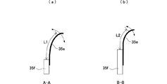
したがって、図4(a),(b)に示すように、トナー落下防止シート35eの長手方向に直交する方向における上記一端部が固定された位置が、長手方向の中央部分とそれ以外の部分とにおいて互いに異なる。
Therefore, as shown in FIGS. 4A and 4B, the position where the one end portion is fixed in the direction orthogonal to the longitudinal direction of the toner
そのため、図4(a)に示すトナー落下防止シート35eの長手方向の中央部分における一端部から他端部までの自由長L1は、図4(b)に示すトナー落下防止シート35eの長手方向の中央部分以外の部分とにおける一端部から他端部までの自由長L2よりも長い。また、クリーニングユニット35は、図4(a),(b)の矢印に示すように、搬送スクリュー35d等の駆動によって振動する。したがって、自由長L2よりも長い自由長L1を有するトナー落下防止シート35eの長手方向の中央部分の方が、トナー落下防止シート35eの長手方向の中央部分以外の部分よりも振幅が大きい。
Therefore, the toner
ここで、紙粉の多くは、画像形成時に給紙トレイ21等から搬送される用紙が捌き部材24によって1枚に捌かれる際、用紙と捌き部材24との摩擦等によって発生する。この発明の実施形態では、捌き部材24は、用紙の副走査方向の中央部分において用紙と接触するため、用紙の副走査方向の中央部分から紙粉が発生する。
Here, most of the paper dust is generated due to friction between the paper and the separating member 24 when the sheet conveyed from the
また、紙粉は、用紙搬送途中に図示しない搬送ローラ等との摩擦によって帯電するので、感光体31の外周部におけるトナー像を転写する際に感光体31の外周部に付着する。
Further, since paper dust is charged by friction with a conveyance roller (not shown) during the conveyance of the paper, it adheres to the outer peripheral portion of the
したがって、感光体31の外周部における紙粉滞留量の多い箇所は、用紙の副走査方向の中央部分に対向する箇所となり、感光体31の軸方向について感光体31の外周部に付着する紙粉の量は異なる。
Accordingly, the portion where the amount of paper dust staying in the outer peripheral portion of the
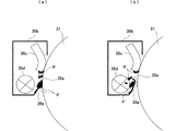
一方、紙粉は流動性が低いので、図5(a)に示すように、クリーニングブレード35によって掻き落とされた紙粉Pは、トナー落下防止シート35eに堆積し易い。さらに、トナー落下防止シート35eは、感光体31の外周部に接触しているので、トナー落下防止シート35eの感光体31の外周部との接触部分及びその周辺にも紙粉が堆積し易い。そのため、長手方向についてトナー落下防止シート35eに堆積する紙粉Pの量の多少は、対向する感光体31の外周部の紙粉滞留量の多少に対応する。
On the other hand, since the paper powder has low fluidity, the paper powder P scraped off by the
上記の構成のように、感光体31の外周部における紙粉滞留量の多い箇所に対向するトナー落下防止シート35eの長手方向の中央部分における自由長L1を、自由長L2よりも長くして振動における振幅を大きくすることで、図5(b)に示すように、振動によって紙粉をトナー落下防止シート35eから容易に剥離して開口部35aから回収することができる。
As described above, the free length L1 at the central portion in the longitudinal direction of the toner
ここで、紙粉がトナー落下防止シート35eの配置箇所よりも矢印Y方向の下流側に位置する開口部35aから回収できるのは、感光体31の矢印Y方向の回転によって矢印Y方向に風が発生するためである。つまり、紙粉Pは、振動により大きな塊にならずにトナー落下防止シート35eから剥離するので、この風の流れに乗って開口部35bに流入する。したがって、紙粉が堆積し易いトナー落下防止シート35eの上記紙粉滞留箇所に対向する部分において紙粉を効率的に回収することができる。
Here, the paper dust can be collected from the
また、上述のように紙粉Pの発生箇所になる捌き部材24に接触する用紙の接触箇所である用紙の副走査方向の中央部分に対応してトナー落下防止シート35eの自由長L1,L2が構成されているので、トナー落下シート35eの感光体31の外周部におけるより正確な紙粉滞留量の多い箇所に対向する部分の自由長L1を長くすることができ、トナー落下防止シート35eにおける紙粉Pの堆積し易い部分において紙粉Pをより効率的に回収することができる。
Further, as described above, the free lengths L1 and L2 of the toner
さらに、シート取付部材35fを用いて自由長L1,L2の長さを構成することによって、上記自由長L1,L2の構成のためにトナー落下防止シート35eにおける感光体31の外周部との接触部分側である他端部の形状が制限されることがないので、上記他端部を用紙の長手方向に平行に形成することで感光体31の外周部と適切に接触させることができ、クリーニングブレード35cによって掻き落とされた紙粉P及び残留トナーをトナー落下防止シート35eで受け止めることができる。
Further, by configuring the lengths of the free lengths L1 and L2 using the
なお、この発明の実施形態では、感光体31の外周部における紙粉滞留箇所を感光体31の軸方向の中央部分としているが、特にこれに限定されることはなく、用紙の紙粉が捌き部材24によって発生する箇所に対向する部分を紙粉滞留箇所とすればよい。
In the embodiment of the present invention, the paper dust staying portion in the outer peripheral portion of the
24−捌き部材
30−画像形成部
31−感光体
35−クリーニングユニット
35a−開口部
35c−クリーニングブレード
35d−搬送スクリュー
35e−トナー落下防止シート
35f−シート取付部材
100−画像形成装置
P−紙粉
24-Rolling member 30-Image forming unit 31-Photoconductor 35-
Claims (3)
前記トナー落下防止シートの一端部はユニット本体に固定されているシート取付部材に取り付けられ、該トナー落下防止シートの他端部は像担持体の外周部に当接し、且つ、前記軸方向に平行に設定され、
前記シート取付部材は、前記トナー落下防止シートの一端部から他端部までの自由長が、前記像担持体の外周部の紙粉滞留量の少ない箇所に対向する部分よりも前記像担持体の外周部の紙粉滞留量の多い箇所に対向する部分の方が長くなるように形成されていることを特徴とするクリーニングユニット。 Residue that adheres to the outer peripheral portion of the image carrier on the unit main body, which is disposed downstream of the position where the toner image is transferred to the paper in the rotation direction of the image carrier and has an opening facing the outer peripheral portion of the image carrier. A cleaning blade that scrapes off the toner, a toner fall prevention sheet that is a sheet whose longitudinal direction is parallel to the axial direction of the image carrier and is located upstream of the opening of the unit body in the rotational direction of the image carrier; In the cleaning unit for collecting the residual toner scraped off by the cleaning blade into the unit body from the opening,
One end portion of the toner drop preventing sheet is attached to the seat mounting member secured to the units main body, the other end portion of said toner drop prevention sheet contacts the outer peripheral portion of the image bearing member, and, in the axial direction Set to parallel,
The sheet mounting member has a free length from one end portion to the other end portion of the toner fall prevention sheet that is less than a portion of the outer peripheral portion of the image carrier facing a portion where the amount of accumulated paper powder is small. cleaning unit towards the portion facing the large portion of the paper dust amount of retention of the outer peripheral portion is characterized that you have been formed to be longer.
前記捌き部材に接触する用紙の接触箇所に近接する像担持体の外周部の箇所に対向するトナー落下防止シートの部分の前記自由長を、前記捌き部材に接触する用紙の接触箇所に近接しない像担持体の外周部の箇所に対向するトナー落下防止シートの部分の前記自由長よりも長くしたことを特徴とする請求項1に記載のクリーニングユニット。 The stored paper is picked up one by one by a separating member and conveyed to a position where a toner image is transferred,
An image of the free length of the portion of the toner fall prevention sheet facing the outer peripheral portion of the image carrier that is in proximity to the contact portion of the sheet that contacts the separating member is not adjacent to the contact portion of the sheet that contacts the separating member. The cleaning unit according to claim 1, wherein the free length of the portion of the toner fall prevention sheet facing the outer peripheral portion of the carrier is longer than the free length.
Priority Applications (3)
| Application Number | Priority Date | Filing Date | Title |
|---|---|---|---|
| JP2003344705A JP3645560B2 (en) | 2003-10-02 | 2003-10-02 | Cleaning unit |
| US10/595,249 US7711285B2 (en) | 2003-10-02 | 2004-10-01 | Cleaning device for an image forming apparatus |
| PCT/JP2004/014511 WO2005033805A1 (en) | 2003-10-02 | 2004-10-01 | Cleaning device |
Applications Claiming Priority (1)
| Application Number | Priority Date | Filing Date | Title |
|---|---|---|---|
| JP2003344705A JP3645560B2 (en) | 2003-10-02 | 2003-10-02 | Cleaning unit |
Publications (2)
| Publication Number | Publication Date |
|---|---|
| JP2005114758A JP2005114758A (en) | 2005-04-28 |
| JP3645560B2 true JP3645560B2 (en) | 2005-05-11 |
Family
ID=34538252
Family Applications (1)
| Application Number | Title | Priority Date | Filing Date |
|---|---|---|---|
| JP2003344705A Expired - Fee Related JP3645560B2 (en) | 2003-10-02 | 2003-10-02 | Cleaning unit |
Country Status (1)
| Country | Link |
|---|---|
| JP (1) | JP3645560B2 (en) |
Families Citing this family (2)
| Publication number | Priority date | Publication date | Assignee | Title |
|---|---|---|---|---|
| JP4680710B2 (en) * | 2005-07-29 | 2011-05-11 | シャープ株式会社 | Cleaning unit |
| JP6500574B2 (en) * | 2015-04-23 | 2019-04-17 | コニカミノルタ株式会社 | Image forming device |
-
2003
- 2003-10-02 JP JP2003344705A patent/JP3645560B2/en not_active Expired - Fee Related
Also Published As
| Publication number | Publication date |
|---|---|
| JP2005114758A (en) | 2005-04-28 |
Similar Documents
| Publication | Publication Date | Title |
|---|---|---|
| US7904014B2 (en) | Waste toner collecting device and image forming apparatus provided with the same | |
| US6463235B1 (en) | Light-sensitive drum mounting/demounting structure, light-sensitive unit provided with the same structure and image-forming device with the same unit | |
| US8634755B2 (en) | Cleaning unit, image carrier unit, and image forming apparatus | |
| US7209700B2 (en) | Cleaning unit | |
| US7711285B2 (en) | Cleaning device for an image forming apparatus | |
| JP3680175B2 (en) | Paper peeling nails | |
| JP3645560B2 (en) | Cleaning unit | |
| JP5216745B2 (en) | Image forming apparatus | |
| JP2008033103A (en) | Image forming apparatus | |
| JP5538276B2 (en) | Cleaning device and image forming apparatus | |
| JP4526371B2 (en) | Sheet conveying apparatus, image forming apparatus, document image reading apparatus, and recording medium post-processing apparatus | |
| JPH04216569A (en) | Image forming device | |
| JP2005208443A (en) | Image forming apparatus | |
| JP4603313B2 (en) | Dust-proof sheet and image forming apparatus | |
| JP3866079B2 (en) | Paper transport device | |
| JP5235500B2 (en) | Sheet conveying apparatus and image forming apparatus | |
| JP5806975B2 (en) | Image forming apparatus | |
| JP3110596B2 (en) | Separation device and image forming device | |
| JP5216750B2 (en) | Image forming apparatus | |
| JP3673720B2 (en) | Cleaning device | |
| JP2001166661A (en) | Image forming device | |
| JP2001042664A (en) | Image forming device | |
| JP2001261178A (en) | Image forming device | |
| JP2007156160A (en) | Cleaning device and image forming apparatus | |
| JP2002072706A (en) | Toner scattering preventing device and image forming device |
Legal Events
| Date | Code | Title | Description |
|---|---|---|---|
| TRDD | Decision of grant or rejection written | ||
| A01 | Written decision to grant a patent or to grant a registration (utility model) |
Free format text: JAPANESE INTERMEDIATE CODE: A01 Effective date: 20050125 |
|
| A61 | First payment of annual fees (during grant procedure) |
Free format text: JAPANESE INTERMEDIATE CODE: A61 Effective date: 20050203 |
|
| R150 | Certificate of patent or registration of utility model |
Ref document number: 3645560 Country of ref document: JP Free format text: JAPANESE INTERMEDIATE CODE: R150 Free format text: JAPANESE INTERMEDIATE CODE: R150 |
|
| FPAY | Renewal fee payment (event date is renewal date of database) |
Free format text: PAYMENT UNTIL: 20080210 Year of fee payment: 3 |
|
| FPAY | Renewal fee payment (event date is renewal date of database) |
Free format text: PAYMENT UNTIL: 20090210 Year of fee payment: 4 |
|
| FPAY | Renewal fee payment (event date is renewal date of database) |
Free format text: PAYMENT UNTIL: 20100210 Year of fee payment: 5 |
|
| FPAY | Renewal fee payment (event date is renewal date of database) |
Free format text: PAYMENT UNTIL: 20100210 Year of fee payment: 5 |
|
| FPAY | Renewal fee payment (event date is renewal date of database) |
Free format text: PAYMENT UNTIL: 20110210 Year of fee payment: 6 |
|
| FPAY | Renewal fee payment (event date is renewal date of database) |
Free format text: PAYMENT UNTIL: 20120210 Year of fee payment: 7 |
|
| FPAY | Renewal fee payment (event date is renewal date of database) |
Free format text: PAYMENT UNTIL: 20120210 Year of fee payment: 7 |
|
| FPAY | Renewal fee payment (event date is renewal date of database) |
Free format text: PAYMENT UNTIL: 20130210 Year of fee payment: 8 |
|
| FPAY | Renewal fee payment (event date is renewal date of database) |
Free format text: PAYMENT UNTIL: 20130210 Year of fee payment: 8 |
|
| FPAY | Renewal fee payment (event date is renewal date of database) |
Free format text: PAYMENT UNTIL: 20140210 Year of fee payment: 9 |
|
| LAPS | Cancellation because of no payment of annual fees |