JP3645106B2 - ANTENNA DEVICE AND PORTABLE RADIO ELECTRONIC DEVICE HAVING THE ANTENNA DEVICE - Google Patents
ANTENNA DEVICE AND PORTABLE RADIO ELECTRONIC DEVICE HAVING THE ANTENNA DEVICE Download PDFInfo
- Publication number
- JP3645106B2 JP3645106B2 JP32214598A JP32214598A JP3645106B2 JP 3645106 B2 JP3645106 B2 JP 3645106B2 JP 32214598 A JP32214598 A JP 32214598A JP 32214598 A JP32214598 A JP 32214598A JP 3645106 B2 JP3645106 B2 JP 3645106B2
- Authority
- JP
- Japan
- Prior art keywords
- antenna
- antenna device
- holder
- spring
- hole
- Prior art date
- Legal status (The legal status is an assumption and is not a legal conclusion. Google has not performed a legal analysis and makes no representation as to the accuracy of the status listed.)
- Expired - Fee Related
Links
Images


Classifications
-
- H—ELECTRICITY
- H01—ELECTRIC ELEMENTS
- H01Q—ANTENNAS, i.e. RADIO AERIALS
- H01Q1/00—Details of, or arrangements associated with, antennas
- H01Q1/12—Supports; Mounting means
- H01Q1/1207—Supports; Mounting means for fastening a rigid aerial element
- H01Q1/1214—Supports; Mounting means for fastening a rigid aerial element through a wall
-
- H—ELECTRICITY
- H01—ELECTRIC ELEMENTS
- H01Q—ANTENNAS, i.e. RADIO AERIALS
- H01Q1/00—Details of, or arrangements associated with, antennas
- H01Q1/12—Supports; Mounting means
- H01Q1/22—Supports; Mounting means by structural association with other equipment or articles
- H01Q1/24—Supports; Mounting means by structural association with other equipment or articles with receiving set
- H01Q1/241—Supports; Mounting means by structural association with other equipment or articles with receiving set used in mobile communications, e.g. GSM
- H01Q1/242—Supports; Mounting means by structural association with other equipment or articles with receiving set used in mobile communications, e.g. GSM specially adapted for hand-held use
-
- H—ELECTRICITY
- H04—ELECTRIC COMMUNICATION TECHNIQUE
- H04B—TRANSMISSION
- H04B1/00—Details of transmission systems, not covered by a single one of groups H04B3/00 - H04B13/00; Details of transmission systems not characterised by the medium used for transmission
- H04B1/38—Transceivers, i.e. devices in which transmitter and receiver form a structural unit and in which at least one part is used for functions of transmitting and receiving
- H04B1/3827—Portable transceivers
- H04B1/3833—Hand-held transceivers
Landscapes
- Engineering & Computer Science (AREA)
- Computer Networks & Wireless Communication (AREA)
- Support Of Aerials (AREA)
- Mobile Radio Communication Systems (AREA)
- Telephone Set Structure (AREA)
Description
【0001】
【発明の属する技術分野】
本発明は、例えば無線機器や携帯電話機等の電子機器ケースの外部より組付けるアンテナ装置に関し、特に給電ばねの抜けを防止するためにリブをケースに設けるよう構成したものである。
【0002】
【従来の技術】
従来、無線機器や携帯電話機等の電子機器ケースの外部より組付けるアンテナ装置において、アンテナをケースに取付るに当たっては図6に示されるような構成を採っていた。すなわち、図6に示されるようにアンテナ11は、ケース14に設けられたアンテナ通し孔を介してホルダー12と給電ばね13とをネジによって一緒に固定するようにしていた。
【0003】
【発明が解決しようとする課題】
しかしながら、上記した従来のアンテナ装置では、ホルダー12と給電ばね13とをネジによって一緒に固定するような構成のため、何らかの原因でネジの緩みなどが生じると給電ばね13の接点位置がずれてしまいアンテナ装置が機能しなくなるという問題を有していた。
【0004】
そこで本発明は、給電ばねの位置ずれや抜けの起きないアンテナ装置を提供することを目的とするものである。
【0005】
【課題を解決するための手段】
上記のような課題を解決するために本発明のアンテナ装置は、孔を介してホルダーと結合するための結合部材を備えるアンテナと、前記孔の近傍にアンテナ挿入方向と平行に給電ばね抜け/給電ばね回転防止リブを植立したケースと、前記孔を介して挿通された前記結合部材と結合するホルダーと、前記ホルダーを巻込むように跨座して係合される給電ばねを備えることを特徴とする。
【0006】
【発明の実施の形態】
本発明における請求項1記載の発明は、孔を介してホルダーと結合するための結合部材を備えるアンテナと、前記孔の近傍にアンテナ挿入方向と平行に給電ばね抜け/給電ばね回転防止リブを植立したケースと、前記孔を介して挿通された前記結合部材と結合するホルダーと、前記ホルダーを巻込むように跨座して係合される給電ばねを備えることを特徴とするアンテナ装置としたものであり、給電ばねの抜け/回転を起こさないようにすることができるという作用を有する。
【0009】
また、請求項2記載の発明は、前記リブのアンテナ挿入方向に沿う先端部には曲率が施されていることを特徴とする請求項1記載のアンテナ装置としたものであり、ホルダーおよび給電ばねの取付を容易化できるという作用を有する。
【0012】
また、請求項3記載の発明は、前記請求項1ないし2記載のアンテナ装置を備える携帯無線電子機器としたものであり、携帯無線電子機器において給電ばねの抜け/回転を起こさないようにすることができるという作用を有する。
【0013】
以下、本発明の実施の形態について、図面を用いて説明する。
【0014】
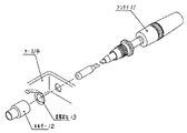
図1は、本発明に係るアンテナ装置の構成を示した分解斜視図である。図1においてアンテナ装置は、孔を介してホルダー2と結合するための結合部材を備えるアンテナ1と、孔の近傍にアンテナ挿入方向と平行に給電ばね抜け防止/回転防止リブ5を植立したケース4と、孔を介して挿通された結合部材と結合するホルダー2と、ホルダー2を巻込むように跨座して係合される給電ばね3を備えるように構成されている。
【0015】
図2は、ケースの孔の近傍を上から見た正面図であり、ケース4からアンテナ挿入方向と平行に給電ばね抜け防止/回転防止リブ5が植立されているのが理解できるであろう。また、給電ばね抜け防止/回転防止リブ5のアンテナ挿入方向に沿う先端部には曲率(アール)が施されているのが理解できるであろう。この曲率(アール)は部品の取付を容易化するために施されるものである。
【0016】
図3は、図2の状態においてさらにホルダー2および給電ばね3を取付けた状態を示す正面図であり、ホルダー2、給電ばね3および給電ばね抜け防止/回転防止リブ5の位置関係が理解されるであろう。
【0017】
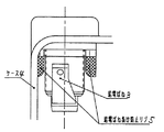
図4は、組立が完了する直前のアンテナ装置の構成を示すケース内から見た拡大立面図であり、図4において既にアンテナはホルダー2と結合されており、給電ばね3をホルダー2に圧力を加えて取付ける様子が示されている。すなわち、ホルダー2に取付けるために給電ばね3に押圧を加えているので、給電ばね3は給電ばね抜け防止/回転防止リブ5に接触せずにホルダー2にその先端部が巻込まれるように且つ接点を持つ面がホルダー2の表面に跨るようにした取付けられる様子が理解できるであろう。この場合給電ばね抜け防止/回転防止リブ5の給電ばね3の取付方向の先端部には傾斜が設けられているのが分かるであろう。
【0018】
図5は、組立が完了した状態のアンテナ装置の構成を示すケース内から見た拡大立面図であり、図5においては既にアンテナ装置としての取付は完了しているので、例えば給電ばね3に矢印方向に引抜こうとする力が働いたと仮定した場合、給電ばね3のばね力により給電ばね3は給電ばね抜け防止/回転防止リブ5に接触しており、引抜こうとするも給電ばね抜け防止/回転防止リブ5によって阻止され引抜くことはできない。
【0019】
また、給電ばね3に回転する力が働いたと仮定した場合、給電ばね3のばね力により給電ばね3は給電ばね抜け防止/回転防止リブ5に接触しており、回転しようとするも給電ばね抜け防止/回転防止リブ5によって阻止され回転することはできない。
【0020】
【発明の効果】
以上の説明から明らかなように本発明は、孔を介してホルダーと結合するための結合部材を備えるアンテナと、前記孔の近傍にアンテナ挿入方向と平行に給電ばね抜け/給電ばね回転防止リブを植立したケースと、前記孔を介して挿通された前記結合部材と結合するホルダーと、前記ホルダーを巻込むように跨座して係合される給電ばねを備えることを特徴とするものであり、給電ばねの抜け/回転を起こさないようにすることができるという効果を有する。
【図面の簡単な説明】
【図1】本発明の実施の形態に係るアンテナ装置の構成を示す分解斜視図、
【図2】本発明の実施の形態に係るアンテナ装置においてケースの孔の近傍を上から見た正面図、
【図3】本発明の実施の形態に係るアンテナ装置においてホルダーおよび給電ばねを取付けた状態を示す正面図、
【図4】組立が完了する直前の本発明の実施の形態に係るアンテナ装置の構成を示すケース内から見た拡大立面図、
【図5】組立が完了した状態の本発明の実施の形態に係るアンテナ装置の構成を示すケース内から見た拡大立面図、
【図6】従来のアンテナ装置の構成を示す分解斜視図である。
【符号の説明】
1、11 アンテナ
2、12 ホルダー
3、13 給電ばね
4、14 ケース
5 給電ばね抜け防止/回転防止リブ[0001]
BACKGROUND OF THE INVENTION
The present invention relates to an antenna device that is assembled from the outside of an electronic device case such as a wireless device or a mobile phone, and is particularly configured to provide a rib in the case to prevent the feeding spring from coming off.
[0002]
[Prior art]
Conventionally, in an antenna device that is assembled from the outside of an electronic device case such as a wireless device or a mobile phone, the configuration shown in FIG. 6 has been adopted when the antenna is attached to the case. That is, as shown in FIG. 6, the antenna 11 is configured to fix the holder 12 and the power supply spring 13 together with screws through an antenna through hole provided in the case 14.
[0003]
[Problems to be solved by the invention]
However, in the conventional antenna device described above, the holder 12 and the feeding spring 13 are fixed together with screws, so that if the screws are loosened for some reason, the contact position of the feeding spring 13 is shifted. There was a problem that the antenna device stopped functioning.
[0004]
SUMMARY OF THE INVENTION An object of the present invention is to provide an antenna device that does not cause displacement or disconnection of a feeding spring.
[0005]
[Means for Solving the Problems]
In order to solve the above-described problems, an antenna device of the present invention includes an antenna including a coupling member for coupling to a holder through a hole, and a feed spring removal / feed in the vicinity of the hole in parallel with the antenna insertion direction. A case in which a spring rotation prevention rib is planted, a holder coupled to the coupling member inserted through the hole, and a power supply spring that is straddled and engaged so as to wind the holder. And
[0006]
DETAILED DESCRIPTION OF THE INVENTION
According to the first aspect of the present invention, an antenna including a coupling member for coupling to a holder through a hole, and a feed spring removal / feed spring rotation prevention rib in the vicinity of the hole parallel to the antenna insertion direction are planted. An antenna device comprising: a standing case; a holder that is coupled to the coupling member that is inserted through the hole; and a feeding spring that is straddled and engaged so as to wind the holder. And has the effect of preventing the feeding spring from coming off / rotating .
[0009]
The invention of claim 2 wherein is for the distal end along the antenna insertion direction of the ribs was that in claim 1 Symbol placement of the antenna device is characterized in that curvature is applied, the holder and the feeding The spring can be easily attached.
[0012]
According to a third aspect of the present invention, there is provided a portable wireless electronic device including the antenna device according to the first or second aspect of the present invention, and the feeding spring is prevented from coming off / rotating in the portable wireless electronic device. Has the effect of being able to
[0013]
Hereinafter, embodiments of the present invention will be described with reference to the drawings.
[0014]
FIG. 1 is an exploded perspective view showing a configuration of an antenna device according to the present invention. In FIG. 1, the antenna device includes a case in which an antenna 1 having a coupling member for coupling to a holder 2 through a hole, and a feeding spring removal prevention / rotation prevention rib 5 in the vicinity of the hole parallel to the antenna insertion direction. 4, a holder 2 that is coupled to a coupling member that is inserted through a hole, and a power supply spring 3 that is straddled and engaged so as to wind the holder 2.
[0015]
FIG. 2 is a front view of the vicinity of the hole of the case as seen from above, and it can be understood that the feed spring removal prevention / rotation prevention rib 5 is planted from the case 4 in parallel with the antenna insertion direction. . Further, it can be understood that a curvature (R) is applied to the tip of the feeding spring removal prevention / rotation prevention rib 5 along the antenna insertion direction. This curvature (R) is given to facilitate the mounting of the parts.
[0016]
3 is a front view showing a state in which the holder 2 and the power supply spring 3 are further attached in the state of FIG. 2, and the positional relationship among the holder 2, the power supply spring 3, and the power supply spring removal prevention / rotation prevention rib 5 is understood. Will.
[0017]
FIG. 4 is an enlarged elevation view seen from inside the case showing the configuration of the antenna device immediately before the assembly is completed. In FIG. 4, the antenna is already coupled to the holder 2, and the feeding spring 3 is pressed against the holder 2. It is shown how it is attached by adding. That is, since the pressing force is applied to the power supply spring 3 for attachment to the holder 2, the power supply spring 3 does not come into contact with the power supply spring removal prevention / rotation prevention rib 5, and the front end of the power supply spring 3 is wound around the holder 2. It will be understood that the surface having the surface is attached so as to straddle the surface of the holder 2. In this case, it will be understood that an inclination is provided at the tip of the feeding spring 3 in the mounting direction of the feeding spring 3 of the feeding spring removal prevention / rotation prevention rib 5.
[0018]
FIG. 5 is an enlarged elevation view seen from inside the case showing the configuration of the antenna device in a state where the assembly is completed. In FIG. 5, since the mounting as the antenna device has already been completed, When it is assumed that a force for pulling out in the direction of the arrow is applied, the power supply spring 3 is in contact with the power supply spring removal prevention / rotation prevention rib 5 by the spring force of the power supply spring 3. / It is blocked by the rotation prevention rib 5 and cannot be pulled out.
[0019]
When it is assumed that a rotating force is applied to the power supply spring 3, the power supply spring 3 is in contact with the power supply spring removal prevention / rotation prevention rib 5 due to the spring force of the power supply spring 3. It is blocked by the prevention / rotation prevention rib 5 and cannot rotate.
[0020]
【The invention's effect】
The present invention As is clear from the above description, the antenna and the antenna insertion direction parallel to the feeding spring fastened securely / feeding spring rotation prevention ribs in the vicinity of the hole with a coupling member for coupling the holder through the hole A holder that is coupled to the coupling member that is inserted through the hole, and a power supply spring that is straddled and engaged so as to wind the holder. There is an effect that the feeding spring can be prevented from coming off / rotating.
[Brief description of the drawings]
FIG. 1 is an exploded perspective view showing a configuration of an antenna device according to an embodiment of the present invention;
FIG. 2 is a front view of the vicinity of the hole of the case as viewed from above in the antenna device according to the embodiment of the present invention;
FIG. 3 is a front view showing a state in which a holder and a feeding spring are attached in the antenna device according to the embodiment of the present invention;
FIG. 4 is an enlarged elevation view seen from the case showing the configuration of the antenna device according to the embodiment of the present invention immediately before the assembly is completed;
FIG. 5 is an enlarged elevation view seen from the case showing the configuration of the antenna device according to the embodiment of the present invention in a state where assembly is completed;
FIG. 6 is an exploded perspective view showing a configuration of a conventional antenna device.
[Explanation of symbols]
1, 11 Antenna 2, 12 Holder 3, 13 Feeding spring 4, 14 Case 5 Feeding spring prevention / rotation prevention rib
Claims (3)
Priority Applications (5)
| Application Number | Priority Date | Filing Date | Title |
|---|---|---|---|
| JP32214598A JP3645106B2 (en) | 1998-11-12 | 1998-11-12 | ANTENNA DEVICE AND PORTABLE RADIO ELECTRONIC DEVICE HAVING THE ANTENNA DEVICE |
| US09/437,933 US6140971A (en) | 1998-11-12 | 1999-11-10 | Antenna device having feeding spring escape prevention ribs |
| EP99122509A EP1001484B1 (en) | 1998-11-12 | 1999-11-11 | Antenna device and portable radio electronic appliance using the same |
| DE69910946T DE69910946T2 (en) | 1998-11-12 | 1999-11-11 | Antenna device and portable electronic radio with such an antenna device |
| CN99123534A CN1131574C (en) | 1998-11-12 | 1999-11-11 | Antenna device |
Applications Claiming Priority (1)
| Application Number | Priority Date | Filing Date | Title |
|---|---|---|---|
| JP32214598A JP3645106B2 (en) | 1998-11-12 | 1998-11-12 | ANTENNA DEVICE AND PORTABLE RADIO ELECTRONIC DEVICE HAVING THE ANTENNA DEVICE |
Publications (2)
| Publication Number | Publication Date |
|---|---|
| JP2000151236A JP2000151236A (en) | 2000-05-30 |
| JP3645106B2 true JP3645106B2 (en) | 2005-05-11 |
Family
ID=18140440
Family Applications (1)
| Application Number | Title | Priority Date | Filing Date |
|---|---|---|---|
| JP32214598A Expired - Fee Related JP3645106B2 (en) | 1998-11-12 | 1998-11-12 | ANTENNA DEVICE AND PORTABLE RADIO ELECTRONIC DEVICE HAVING THE ANTENNA DEVICE |
Country Status (5)
| Country | Link |
|---|---|
| US (1) | US6140971A (en) |
| EP (1) | EP1001484B1 (en) |
| JP (1) | JP3645106B2 (en) |
| CN (1) | CN1131574C (en) |
| DE (1) | DE69910946T2 (en) |
Families Citing this family (3)
| Publication number | Priority date | Publication date | Assignee | Title |
|---|---|---|---|---|
| JP2011061549A (en) * | 2009-09-10 | 2011-03-24 | Panasonic Corp | Mobile terminal |
| US8531348B2 (en) | 2009-10-06 | 2013-09-10 | Ralink Technology Corp. | Electronic device with embedded antenna |
| CN203180042U (en) * | 2013-01-31 | 2013-09-04 | 国基电子(上海)有限公司 | Electronic device |
Family Cites Families (10)
| Publication number | Priority date | Publication date | Assignee | Title |
|---|---|---|---|---|
| US4190839A (en) * | 1977-12-13 | 1980-02-26 | American Antenna Corporation | Mobile antenna including quick-release mounting |
| DE3233976C1 (en) * | 1982-09-14 | 1983-08-25 | Daimler-Benz Ag, 7000 Stuttgart | Anti-rotation safeguard for bolts |
| IT206553Z2 (en) * | 1985-07-09 | 1987-08-10 | Zendar Spa | FIXED SUPPORT FOR ANTENNAS |
| FR2631661B1 (en) * | 1988-05-18 | 1990-09-14 | Mecaniplast | DEVICE FOR FIXING AN ANTENNA BASE ON A METAL WALL COVERED WITH AN INSULATING PROTECTIVE LAYER, AND TOOTHED WASHER FOR SUCH A DEVICE |
| DE4126604A1 (en) * | 1991-08-12 | 1993-02-18 | Bosch Gmbh Robert | Electrical connecting terminal for antenna plug connector - has metal press as contact element loaded by clamping screw to securely engage with connecting wire |
| FR2694138B1 (en) * | 1992-07-24 | 1994-08-19 | Alcatel Radiotelephone | Adaptation system between an antenna plug and a base of a radiotelephone. |
| JP2536811B2 (en) * | 1992-10-29 | 1996-09-25 | 株式会社タムラ電子 | Connector for antenna connection |
| JPH08139509A (en) * | 1994-11-10 | 1996-05-31 | Kokusai Electric Co Ltd | Fitting structure for antenna |
| FI955125A (en) * | 1995-10-27 | 1997-04-28 | Nokia Mobile Phones Ltd | Antenna connection |
| JPH10233608A (en) * | 1997-02-19 | 1998-09-02 | Sony Corp | Portable radio equipment and antenna system |
-
1998
- 1998-11-12 JP JP32214598A patent/JP3645106B2/en not_active Expired - Fee Related
-
1999
- 1999-11-10 US US09/437,933 patent/US6140971A/en not_active Expired - Lifetime
- 1999-11-11 CN CN99123534A patent/CN1131574C/en not_active Expired - Fee Related
- 1999-11-11 DE DE69910946T patent/DE69910946T2/en not_active Expired - Lifetime
- 1999-11-11 EP EP99122509A patent/EP1001484B1/en not_active Expired - Lifetime
Also Published As
| Publication number | Publication date |
|---|---|
| EP1001484A1 (en) | 2000-05-17 |
| EP1001484B1 (en) | 2003-09-03 |
| DE69910946T2 (en) | 2004-05-19 |
| US6140971A (en) | 2000-10-31 |
| DE69910946D1 (en) | 2003-10-09 |
| CN1254204A (en) | 2000-05-24 |
| CN1131574C (en) | 2003-12-17 |
| JP2000151236A (en) | 2000-05-30 |
Similar Documents
| Publication | Publication Date | Title |
|---|---|---|
| KR101310229B1 (en) | Structure for protruding a connector in an electronic device | |
| JP2001048428A (en) | Cord storing device | |
| US6912291B2 (en) | Structure of a receptacle for earphone wire | |
| US20020074442A1 (en) | Wire winding box with increasing area | |
| JP3645106B2 (en) | ANTENNA DEVICE AND PORTABLE RADIO ELECTRONIC DEVICE HAVING THE ANTENNA DEVICE | |
| US6575781B2 (en) | Power supply apparatus with power cord securing device | |
| EP1619746B1 (en) | Antenna mount for mobile terminal | |
| JP3591589B2 (en) | Communication connector protection method and card type device using a rotating antenna | |
| JP2518150B2 (en) | Portable radio and its mounting structure | |
| JP4240687B2 (en) | Antenna mounting structure for mobile communication equipment | |
| JPH1168433A (en) | Radio equipment | |
| JP2004336155A (en) | Wireless card | |
| JP2954020B2 (en) | Battery holding structure for portable communication device | |
| JP2002009911A (en) | Portable terminal device | |
| KR200178343Y1 (en) | Ear-mike set | |
| JP3048050U (en) | Belt clip structure | |
| KR100617803B1 (en) | Interface connector cover of wireless terminal | |
| CN215871797U (en) | Headphone with can dismantle microphone | |
| KR19980068861U (en) | Earphone Set for Mobile Phone | |
| KR100355832B1 (en) | The structure of antenna for display device | |
| KR200338281Y1 (en) | A Device for Locking Battery Pack of Communication Terminal | |
| JP2004199892A (en) | Mounting and demounting structure of connector cover | |
| JPH10125393A (en) | Dustproof cap | |
| JP3501338B2 (en) | Flat flexible cable | |
| JP2546600Y2 (en) | Inner phone |
Legal Events
| Date | Code | Title | Description |
|---|---|---|---|
| A977 | Report on retrieval |
Free format text: JAPANESE INTERMEDIATE CODE: A971007 Effective date: 20040805 |
|
| A131 | Notification of reasons for refusal |
Free format text: JAPANESE INTERMEDIATE CODE: A131 Effective date: 20041102 |
|
| A521 | Written amendment |
Free format text: JAPANESE INTERMEDIATE CODE: A523 Effective date: 20041228 |
|
| TRDD | Decision of grant or rejection written | ||
| A01 | Written decision to grant a patent or to grant a registration (utility model) |
Free format text: JAPANESE INTERMEDIATE CODE: A01 Effective date: 20050201 |
|
| A61 | First payment of annual fees (during grant procedure) |
Free format text: JAPANESE INTERMEDIATE CODE: A61 Effective date: 20050202 |
|
| R150 | Certificate of patent or registration of utility model |
Free format text: JAPANESE INTERMEDIATE CODE: R150 |
|
| FPAY | Renewal fee payment (event date is renewal date of database) |
Free format text: PAYMENT UNTIL: 20080210 Year of fee payment: 3 |
|
| FPAY | Renewal fee payment (event date is renewal date of database) |
Free format text: PAYMENT UNTIL: 20090210 Year of fee payment: 4 |
|
| FPAY | Renewal fee payment (event date is renewal date of database) |
Free format text: PAYMENT UNTIL: 20100210 Year of fee payment: 5 |
|
| FPAY | Renewal fee payment (event date is renewal date of database) |
Free format text: PAYMENT UNTIL: 20100210 Year of fee payment: 5 |
|
| FPAY | Renewal fee payment (event date is renewal date of database) |
Free format text: PAYMENT UNTIL: 20110210 Year of fee payment: 6 |
|
| FPAY | Renewal fee payment (event date is renewal date of database) |
Free format text: PAYMENT UNTIL: 20120210 Year of fee payment: 7 |
|
| FPAY | Renewal fee payment (event date is renewal date of database) |
Free format text: PAYMENT UNTIL: 20130210 Year of fee payment: 8 |
|
| FPAY | Renewal fee payment (event date is renewal date of database) |
Free format text: PAYMENT UNTIL: 20130210 Year of fee payment: 8 |
|
| FPAY | Renewal fee payment (event date is renewal date of database) |
Free format text: PAYMENT UNTIL: 20140210 Year of fee payment: 9 |
|
| LAPS | Cancellation because of no payment of annual fees |