JP3643125B2 - Method and fuel injector enabling precise setting of valve lift - Google Patents
Method and fuel injector enabling precise setting of valve lift Download PDFInfo
- Publication number
- JP3643125B2 JP3643125B2 JP50890698A JP50890698A JP3643125B2 JP 3643125 B2 JP3643125 B2 JP 3643125B2 JP 50890698 A JP50890698 A JP 50890698A JP 50890698 A JP50890698 A JP 50890698A JP 3643125 B2 JP3643125 B2 JP 3643125B2
- Authority
- JP
- Japan
- Prior art keywords
- valve body
- valve
- body shell
- fuel injector
- armature
- Prior art date
- Legal status (The legal status is an assumption and is not a legal conclusion. Google has not performed a legal analysis and makes no representation as to the accuracy of the status listed.)
- Expired - Fee Related
Links
- 239000000446 fuel Substances 0.000 title claims description 57
- 238000000034 method Methods 0.000 title claims description 50
- 238000003466 welding Methods 0.000 claims description 30
- 239000000463 material Substances 0.000 claims description 25
- 230000008569 process Effects 0.000 claims description 10
- 230000006835 compression Effects 0.000 claims description 6
- 238000007906 compression Methods 0.000 claims description 6
- 238000003780 insertion Methods 0.000 claims description 6
- 230000037431 insertion Effects 0.000 claims description 6
- 238000002485 combustion reaction Methods 0.000 claims description 5
- 239000012530 fluid Substances 0.000 claims description 5
- 239000000696 magnetic material Substances 0.000 claims description 2
- 239000002356 single layer Substances 0.000 claims 1
- 230000000694 effects Effects 0.000 description 5
- 230000004907 flux Effects 0.000 description 5
- 230000009471 action Effects 0.000 description 4
- 238000002347 injection Methods 0.000 description 4
- 239000007924 injection Substances 0.000 description 4
- 229910001220 stainless steel Inorganic materials 0.000 description 4
- 239000010935 stainless steel Substances 0.000 description 4
- 238000000429 assembly Methods 0.000 description 3
- 230000008859 change Effects 0.000 description 3
- 238000001816 cooling Methods 0.000 description 3
- 238000004519 manufacturing process Methods 0.000 description 3
- 238000005259 measurement Methods 0.000 description 3
- 230000006872 improvement Effects 0.000 description 2
- 238000003754 machining Methods 0.000 description 2
- 230000013011 mating Effects 0.000 description 2
- 230000003313 weakening effect Effects 0.000 description 2
- 230000006978 adaptation Effects 0.000 description 1
- 230000000712 assembly Effects 0.000 description 1
- 230000004323 axial length Effects 0.000 description 1
- 230000008602 contraction Effects 0.000 description 1
- 238000005260 corrosion Methods 0.000 description 1
- 230000007797 corrosion Effects 0.000 description 1
- 238000010586 diagram Methods 0.000 description 1
- 230000014759 maintenance of location Effects 0.000 description 1
- 239000002184 metal Substances 0.000 description 1
- 238000011017 operating method Methods 0.000 description 1
- 230000009467 reduction Effects 0.000 description 1
- 238000007789 sealing Methods 0.000 description 1
- 125000006850 spacer group Chemical group 0.000 description 1
- 239000007921 spray Substances 0.000 description 1
- 230000007704 transition Effects 0.000 description 1
- 238000011144 upstream manufacturing Methods 0.000 description 1
Images


Classifications
-
- F—MECHANICAL ENGINEERING; LIGHTING; HEATING; WEAPONS; BLASTING
- F02—COMBUSTION ENGINES; HOT-GAS OR COMBUSTION-PRODUCT ENGINE PLANTS
- F02M—SUPPLYING COMBUSTION ENGINES IN GENERAL WITH COMBUSTIBLE MIXTURES OR CONSTITUENTS THEREOF
- F02M61/00—Fuel-injectors not provided for in groups F02M39/00 - F02M57/00 or F02M67/00
- F02M61/16—Details not provided for in, or of interest apart from, the apparatus of groups F02M61/02 - F02M61/14
- F02M61/168—Assembling; Disassembling; Manufacturing; Adjusting
-
- F—MECHANICAL ENGINEERING; LIGHTING; HEATING; WEAPONS; BLASTING
- F02—COMBUSTION ENGINES; HOT-GAS OR COMBUSTION-PRODUCT ENGINE PLANTS
- F02M—SUPPLYING COMBUSTION ENGINES IN GENERAL WITH COMBUSTIBLE MIXTURES OR CONSTITUENTS THEREOF
- F02M51/00—Fuel-injection apparatus characterised by being operated electrically
- F02M51/06—Injectors peculiar thereto with means directly operating the valve needle
- F02M51/061—Injectors peculiar thereto with means directly operating the valve needle using electromagnetic operating means
- F02M51/0625—Injectors peculiar thereto with means directly operating the valve needle using electromagnetic operating means characterised by arrangement of mobile armatures
- F02M51/0664—Injectors peculiar thereto with means directly operating the valve needle using electromagnetic operating means characterised by arrangement of mobile armatures having a cylindrically or partly cylindrically shaped armature, e.g. entering the winding; having a plate-shaped or undulated armature entering the winding
- F02M51/0671—Injectors peculiar thereto with means directly operating the valve needle using electromagnetic operating means characterised by arrangement of mobile armatures having a cylindrically or partly cylindrically shaped armature, e.g. entering the winding; having a plate-shaped or undulated armature entering the winding the armature having an elongated valve body attached thereto
-
- F—MECHANICAL ENGINEERING; LIGHTING; HEATING; WEAPONS; BLASTING
- F02—COMBUSTION ENGINES; HOT-GAS OR COMBUSTION-PRODUCT ENGINE PLANTS
- F02M—SUPPLYING COMBUSTION ENGINES IN GENERAL WITH COMBUSTIBLE MIXTURES OR CONSTITUENTS THEREOF
- F02M2200/00—Details of fuel-injection apparatus, not otherwise provided for
- F02M2200/80—Fuel injection apparatus manufacture, repair or assembly
- F02M2200/8061—Fuel injection apparatus manufacture, repair or assembly involving press-fit, i.e. interference or friction fit
Description
発明の技術分野
本発明は内燃エンジンに使用する燃料噴射器、とくに噴射器からの適当な燃料流量を簡単かつ信頼性をもって得るため燃料噴射器の弁要素のリフト(lift)の精密設定を可能にする操作方法および噴射器に関するものである。
発明の背景
燃料噴射器のリフトは、弁要素が弁の閉鎖および開放位置間を移動する距離である。弁要素は、ソレノイド作動器が消勢されて閉鎖ばねが弁要素を弁座に移動させるとき閉鎖位置となって、燃料は噴射器チップから流出しない。弁要素は、ソレノイドが付勢されて弁要素を弁座から流入管の端部に設けられた固定停止片に磁気的に引張るとき開放位置をとり、ソレノイドが付勢される期間噴射器から燃料が流出することを可能にする。
弁リフトの設定は、エンジンの設計が一層厳しい排出物減少基準(reduced emissions standards)が設定されるとき絶えず厳しくなる。これらの設計は燃料流量に対するエンジン制御によって各エンジンシリンダにおける一層精密な制御を必要とする。
弁リフトを大きい値に設定すると燃料流量に対するリフト変化の効果を減少するが、大きい弁リフト設計の性能は、磁束に対する一層大きい抵抗によって影響される。
小さい弁リフトは好適であるが、小さい値におけるリフト高さの変化は流量に一層大きい効果を生じ、したがってリフト高さは許容しうるリフト高さの変化の一層厳しい制限によって精密に設定されなければならない。
リフトを設定する一つの方法は、サブアッセンブリ(subassemblies)における厳しい公差で機械加工された部品の長さへの適合を必要とする。リフトは弁が開放されるときそれに向かって移動する適当な停止板によって設定される。これは巧妙に実施される方法であったが、部品グループの適合または適合すべき加工要素に加えて、厳しい公差を必要とし、厳しく制御された弁リフトを得る方法を高価なものにする。
“燃料噴射器リフトを制御する方法”と称する1986年9月9日に特許されたヘンスレーの米国特許第4610080号明細書には、頂部サブアッセンブリの長さおよび底部サブアッセンブリの長さを測定すること、ついで所望のリフトに適合するリフトスペーサシムを変形し、サブアッセンブリの長さの変化を調節することによりサブアッセンブリの長さの公差を甘くすることを可能にする別の方法が記載されている。この方法は、シム変形の性質のため、安価であるが、所望のリフト設定を必ずしも達成しないためスクラップを生ずる。
さらに、通常のシムに必要な空間が最少であるにしても、サブアッセンブリにおける公差の集積はシムの変形に対して考慮されなければならない。このことは変形したシムの内径および外径に対して大きい広がり(population)をもたらす。通常の噴射器の外形は、シムの内径および外径に対して適合可能であったが、最近の噴射器外径の小形化において、このリフト設定プロセスは所要空間のため好ましくないものとした。さらに、シムの高さは噴射器に使用されるシール用O−リングの高さの圧縮に関連し、あるサブアッセンブリの組合わせは推奨される安全範囲外のO−リング圧縮をもたらし、スクラップを生ずる。
リフト設定の一層最近の方法は、オリフィスディスク(orifice desk)を座に溶接し、ついでオリフィスを弁体に溶接することを含んでいる。ついでオリフィスディスクは所望のリフトを得るため変形される。この方法は費用相当のもので、サブアッセンブリに生ずる最終的公差を最終的リフト設定操作において取入れることを可能にするが、リフトを達成するためのオリフィスディスクの変形は、とくにもしかなりの変形が必要であるならば、噴射性能であるオリフィスの本来の機能に負の影響を及ぼしかねない。
どのようなリフト設定方法が使用されるようとも、これらの面の整合状態からの逸脱が表面が摩耗するときリフトの変化をもたらすため、接触するアーマチュアおよび極片面の整合(squareness)を維持しなければならない。
したがって、アンチロックブレーキ制御弁に関連した差込み式弁部分(telescoped valve parts)によって弁開放位置を設定する方法が実施されてきたが、噴射リフト設定は一層精密で、したがってかかる方法論によっては設定されなかった。
米国特許第5494225号明細書(US−A−5494225)は、金属製弁本体部分を腐蝕から保護するためその外側に装着した非金属製円筒形シェルを有する燃料噴射器を開示している。この燃料噴射器は、ハウジング内に取付けられたニードル弁アーマチュア組立体を有し、該ハウジングは気密レーザ溶接によって流体密(fluid−tight manner)で一緒に接合された複数の要素を有する。
本発明の目的は、所定の噴射器生産工程においてリフト変化が最小の、比較的安価な燃料噴射器における弁要素の正確なリフト設定方法を得ることにある。
本発明の別の目的は、シムを必要としない、コンパクトな噴射器外形に適合する、噴射器噴霧パターンを阻害しない、信頼性のある正確な噴射器用弁リフト設定方法を得ることにあり、しかも弁リフト距離は長いサービス期間に亘って維持される。
発明の要約
本発明の一つのアスペクトによれば、内燃エンジン用燃料噴射器において所望の弁リフト(valve lift)を設定する方法であって、該燃料噴射器がアーマチュアに取付けられたニードル弁を備えるニードル弁アーマチュア組立体を含み、前記ニードル弁アーマチュア組立体が弁体部材の孔内において摺動可能であり;弁座が前記弁体部材の端部に固定されかつ前記ニードル弁のチップ(tip)が係合可能であり、前記アーマチュアはその付勢の際ソレノイド作動器組立体の極片(pole piece)の端面に接触する移動可能な端面を有し、前記アーマチュアの移動が前記ニードル弁のチップすなわち先部を移動し前記弁座から離して前記弁リフトを画定する前記方法であって、該方法が、a)弁体シェル部材を前記弁体部材上に装着し、b)前記弁体シェル部材を前記極片に対して固定する、各工程を含む方法において、前記方法がさらに、c)前記弁体部材を前記弁体シェル部材内に差込み、d)所望の弁リフトに対応する設定位置に達する時期を決定するため前記弁体シェル部材と前記弁体部材との相対的位置を測定し、e)前記弁体部材および前記弁体シェル部材の部分を締まり嵌めして、前記部材を共に差込んでそれらの間に機械的インターロックを形成するとき一方の部材から材料を変位させ、前記一方の部材は他方の部材より一層変形可能な材料から構成されている、各工程を含むことを特徴とする内燃エンジン用燃料噴射器において、所望の弁リフトを設定する方法が得られる。
本発明の他のアスペクトによれば、燃料レールのシートに取付けられるように構成された燃料噴射器であって、噴射器ハウジングと、前記ハウジング内のソレノイド作動コイルと、前記ソレノイドコイル内に位置する極片部分(pole piece portion)を有する流入管であって、該流入管が燃料レールから燃料流をうけ入れる内部孔を有し、前記極片部分が固定停止片(fixed stop)を画定する端面を有する流入管と、前記ソレノイドコイルが付勢されるとき前記極片端面に向かって上昇するように構成された端面を有するアーマチュアを有し、また装着された細長い弁要素を備えたアーマチュア/弁要素組立体と、その一端に固定され貫通する孔と整合した弁座部材を有する弁体であって、前記アーマチュア/弁要素組立体が前記孔に摺動可能にうけ入れられ、前記弁座が開口を有して、開放したとき燃料が前記弁体の孔から流出することを可能にし、前記弁要素は前記アーマチュアに係合すべく取付けられた圧縮ばねによって押されて前記弁座と係合するチップ即ち先部を有し、前記チップは前記弁座と係合したとき燃料流を停止し、前記ソレノイドコイルは付勢されると前記弁チップを引いて前記弁座との係合を外し、前記アーマチュアが前記極片部分の端面に向かって引かれるとき前記弁体の孔から燃料が流出することを可能にする前記弁体と、前記弁体上の弁体シェルと、を有する燃料噴射器において、前記弁体シェルが直径部分によって前記弁体上に差込まれ、前記弁体シェルおよび弁体の差込み移動により前記直径部分の一方から変位した材料によって締まり嵌めされ前記弁体シェルと弁体との間に機械的インターロックを形成し、前記弁体シェルおよび弁体の一方は他方より一層変形可能な材料から構成されており、前記弁体シェルが前記極片に隣接するその上端において前記極片にまた前記弁体に固体され、それにより前記弁体および弁体シェルの相対的差込み位置が所望の弁リフトに設定されることを特徴とする燃料噴射器が得られる。
下記の明細書および請求の範囲の一読によって明瞭になるであろう、本発明のこれらのおよび他の目的は、弁体に差込むる弁体シェル部材の作用によって達成される。弁体シェルは極片に固定され、弁体は弁体と弁体シェル部材との相対的位置が弁リフトを決定するようにそれに固定された弁座を有する。これらの部材は所望のリフトに対応する相対的位置に達するまで差込まれ、この測定装置によって検出される。弁体および弁体シェル部材は、その後、相対的位置に永久的に維持するため溶接される。
弁体シェルは、その上端にまたソレノイド極片として作用する流入管の一端に溶接された非磁性シェル延長部を有し、延長部は極片上に案内される。シェル延長部は弁体シェルの下端が弁体に気密溶接されるとき、流体を収容するため気密溶接される。弁体は孔を有し、その中に弁要素をアーマチュア(armature)が通常の噴射器のように噴射作用中摺動可能である。アーマチュアはシェル延長部の孔内でも摺動可能である。非磁性弁体シェル延長部は、極片上で案内される内部項を有する。この剛性の溶接された組立体は、アーマチュアおよび流入管極片の端面の正確さが、弁体と弁体シェルの抜差しがリフトを設定するため生ずるとき維持されることを確実にする。
本発明方法を実施するとき、噴射器の二つの組立体、すなわち流入管および弁体シェルを含む動力グループおよび弁体および弁座を含む弁グループは予め組立てられる。
これらのサブアッセンブリ要素が最初に組立てられるとき、最終の所定のリフトより大きいリフトが、リフトが弁体および弁体シェル部材をさらに前進せしめることにより調節可能とするように、形成される。
弁体および弁体シェルが、所望のリフトに対応する最終寸法位置に差込まれるとき締まり嵌めして機械的に相互にインタロックする直径をもつような大きさにされ、そこで各部材は溶接に先立って設定位置に固定される。
部品上部のプレス嵌めも、隙間の可能性を除去することにより信頼性あるソレノイド作用に対する磁束通路を確保する。締まり嵌め(tight fit)は、不整合状態によって弁リフトが徐々に変化することを回避するように、合致する管面に対応するアーマチュア運動の整合を維持する。
締まり嵌めはまた、下記に記載するように、溶接収縮による溶接後シフト(postweld shifting)に抵抗するのを助ける。
測定装置から信号をうけ入れる閉回路制御装置が、燃料噴射器製造方法に適合するためサーボモータを制御するために使用可能である。
弁体および弁体シェルは、それらを最終設定位置に一緒に固定するため、またシールを使用しないで流体を完全に収容するため気密溶接される。
この基本的方法の改良において、弁体および弁体シェルの直径の間の締まり嵌め(interference fit)の局部的量域が、各部材がそれらの最終的設定位置に差込まれるとき、局部的部分に隣接して位置する一層堅い材料の他方の部材の溝内への、一層可撓性の材料から構成されたこれらの材料の一方の部材の進入を生ずる。この改良において、両部材は僅かにプレス嵌めされ溶接に先立って両部材を設定位置に保持する部分をもちまたはもたないことができ、またはそうでなければ、両部材は機械的インタロックによって組合わされるすきま嵌めとすることができる。
この作用は弁体および弁体シェルの間に機械的インタロックを生じ、弁の設定リフトを減少する傾向のある溶接材料の収縮によって生ずる相対的シフトを最小にするものである。
別の改良において、中間の弱体化溝が、溶接収縮が各部分の軸線方向シフトよりむしろ半径方向の引張りを生ずるように設けることができ、弁の設定リフトをシフトする傾向のある溶接の冷却の収縮作用を最小にする。
図面の説明
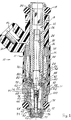
図1は本発明による燃料噴射器の長手方向断面図。
図2は、締まり嵌めおよびリフトの設定に先立つ各部分の溶接後のリフトを安定化する機械的インターロックを形成するため使用される隙間溝を示す、図1に示された噴射弁の一部の拡大断面図。
図2Aは、締まり嵌めによって形成された機械的インターロック、および弁体およびシェル部材のシフトの際の隙間溝部分の拡大破断断面。
図3は、弁体およびシェル部材の交錯部分の別の形式の拡大破断断面。
図3Aは、図3に示された部分の各部材のリフト設定および溶接後の図。
図4は、弁体およびシェル部材の交錯部分の別の形式の拡大破断断面。
図5は、弁体およびシェル部材の交錯部分のさらに別の形式の拡大破断断面。
図6は、噴射器の動力グループおよび弁グループのサブアッセンブリの予備組立れたキー寸法の測定の簡単化された線図的表示。
図7は、動力グループおよび弁グループの要素の最初の組立体の線図的表示。
図8A−図8Gは、弁リフトを設定するため使用されるリフト設定装置および方法の線図的表示。
図9は設定された弁リフトを固定するため使用されるレーザ溶接工程の線図。
詳細な説明
下記の詳細な説明において、ある特殊な用語が明瞭のため使用され、また特殊な実施例が35USC112の要求に従って記載されるが、それは限定を意図するものでなく、本発明が請求の範囲の記載内で多くの形式および変形をなし得るからそのように理解すべきでない。
図面とくに図1を参照すると、本発明による完全に組立てられた燃料噴射器10が示され、噴射器10は(図示しない)接続装置(wiring harness)の電気コネクタをうけ入れる一側から突出する電気コネクタ部分14を含む長い、上部にモールドされた外側ハウジング12を有する。燃料噴射器の一般的構造は、1996年2月27日に発行された米国特許第5494223号、5494224号およぴ5494225号各明細書に示されている。
流入管16は外側ハウジング12の上端から延長し、(図示しない)燃料レール上に形成された対応するうけ入れカップ(mating receptacle cup)に設置されるように構成されている。適当なO−リングシール18が設けられ、保持構造(retention feature)19が噴射器10を燃料レール内の所定位置にロックするため設けられている。
フィルタプラグ20が、その中に噴射器10が設置される、燃料レールから高圧の燃料をうけ入れる流入管16の孔22の上端に挿入される。
孔22の中間部分24は、管26の下方または下流端の下にある圧縮ばね28の力を調節するため長手方向に移動可能な調節管26をうけ入れている。圧縮ばね28の他端はアーマチュア32の孔30の端壁に圧縮されている。図示しない工具が、適当なばね力が設定されるとき、流入管16を調節管26に圧縮するため側方から作用し、図示の外部リブは固定把持作用を確実にしている。
環状作動ソレノイドコイル組立体34が外側ハウジング12内に取付けられ、流入管16の下端を囲んでいる。コイルハウジング36が溶接部38において流入管16に溶接され、また溶接部40において弁体シェル42に溶接されている。
ソレノイドコイル44は電流を接点46を通して供給する電気装置によって付勢される。
アーマチュア32は、長いニードル形弁要素50の上端が固定するためそこにクリングされた、縮小直径管状端部48を有する。
弁要素50の下方、自由端は、丸いチップ(rounded tip)52を形成され、チップ52はばね28によって押されて弁座56の円錐面54に係合せしめられる。
弁座56は、弁チップ52が面54から上昇したとき、高圧燃料が噴射器の出口端から噴射するため流出可能で、弁チップ52が弁座66に着座するとき燃料流が停止するように、整合した流出孔58を有する。
弁座56は、全体的に管状の弁体60の下端に、一端における堆積された案内ディスク64とフィルタスクリーン66、および弁座の他端におけるオリフィスディスク68およびバックアップワッシャ70の間に孔部分62においてうけ入れられることにより固定される。堆積された要素はすべて、流出端において弁体60のクリンプされた端部によって、弁体の肩または段部72に係合して保持される。
燃料噴射器10の流出端は、(図示されない)吸込みマニホルドまたはシリンダヘッドのポケットにうけ入れられ、適当なO−リングシール74によりシールされる。
弁体60は主要孔部分76を有し、その中にアーマチュア32および弁要素50が配置されている。燃料はアーマチュア32の横通路77を通って主要孔に進入する。
弁要素50の下端は案内ディスク64中央孔内で摺動可能に案内され、一方アーマチュア32の上端は弁体主要孔部分76の上端にうけ入れられた成形金属案内アイレット(eyelet)78に摺動可能に案内される。アイレット78の案内孔は、アイレット78が弁体主要孔部分76の上端にクリンプされた後、工具によって精密に成形することができる。
弁体シェル部材42は組立て中、相対的に移動可能になるように弁体60上に差込まれる。
弁リフトまたはソレノイドコイル44付勢の際弁要素が移動しうる距離は、アーマチュア32の上流端面80と流入管16の下端部分よりなる、ソレノイド極片の端面82との間の距離によって画定される。
この距離は、一方の部材、すなわち弁体シェル42を他方の部材、すなわち弁体60の外径上に差し込んで嵌合しかつそれらの部材を弁リフトを調節するためシフトすることによって、変化させることができる。調節の可能性は、一方の部材、すなわち弁体シェル42が流入管16の極片部分に対して、流入管16の極片部分上を案内される上方部分86を有する、段付き直径の管状非磁性弁体シェル延長部94によって固定されるために生ずる。弁体シェル延長部94の下方部分88は弁体シェル42の上端の端ぐり孔(counterbore)にうけ入れられる。
気密溶接部90は上方部分86を流入管16に、気密溶接部92は下方部分88を弁体シェル42の上端に固定し、両方の溶接部はO−リングなしで流体収容部を形成する。上記のように、弁体シェル42は非気密性溶接によってコイルハウジング36に固定される。
弁体シェル延長部94は、磁束の線が、アーマチュア32を上方に引かせるため、主としてアーマチュア32を通過すべきであるので、磁界を転じてはならない。
このため、下方部分延長部88は、シリーズ300ステンレス鋼(Series300stainless steel)のような非磁性材料から構成されなければならず、一方弁体シェル42と弁体60は、それらがソレノイド44が付勢されるとき形成される磁束の線に対する通路を提供しなければならないため、416および430FRのような一層磁気透過性の材料のものとすべきである。レーザ溶接工程はステンレス鋼材料に対する気密溶接の必要性のため使用される。
弁体60および弁体シェル42が組立てられるとき、直径部分96,97はプレス嵌めされる。この嵌合は、下記に記載する溶接工程の完了の前後に所定のリフトを設定するためシフトされるとき、これらの部材を設定位置に維持するのを助ける傾向がある。プレス嵌めは、また隙間を回避する良好な磁束通路を確保し、整合を維持するのを助ける。
プラスチックカバーシェル98は溶接後設置される。
製造中、二つのサブアセンブリ、すなわち弁グループ128Aおよび動力グループ128Bは、図7に示されたように、カバーシェル98を除いて完全に組立てられる。
弁体60および弁体シェル42は各サブアセンブリ128A、128Bを含むが、これらのサブアセンブリが弁リフトを設定する工程の一部として一緒に組立てられるとき、特殊な方法で嵌合される。
上記のように、弁体シェル42および弁体60の主要嵌合部分は、弁体60の外径99を、図2に示すように弁体シェル42の内径104より大きいような寸法にすることによりプレス嵌めされる。たとえば、外径99は9.275±0.025mmの直径を有し、内径104は9.212±0.02mmの直径を有する。上端の弁体60の小径の入口部分95はプレス嵌め組立の開始を容易にする。
図2は、弁グループ128Aおよび動力グループ128Bが組立てられかつ溶接されるときの、弁体60および弁体シェル42の相対的位置を示す。弁体シェル42の内径104は弁体60の隣接する外径105より小さい。たとえば、直径105は9.45±0.025mmとすることができる。弁体シェル42はまたそれらの間の滑り嵌めによって直径105上に載置する、直径103を有する小径の溶接スカート97を有する。
弁体60と弁体シェル42との間の、一層実質的な締まり嵌めの局部的領域100(図1)はロック溝102を備えており、それは下記に一層詳細に記載されるように、リフト設定工程中形成される機械的インターロックを生ずる。
この最初の組立状態において、リフトは所望の設定リフトより大きくなるように設計される。
部材42,60は記載される弁リフト設定工程においてさらに差込まれる。弁体シェル42の材料(430FR)は弁体60の材料(416)より一層可撓性であり、そこで弁体シェル42の張出し108は、リフトが設定されるとき溝102内に変位せしめられる(図2A)。最終リフトが設定されると、弁体シェル42の端部は、弁体60の外径にすみ肉溶接(fillet weld)122により気密に溶接され、これらの垂直面によってすみ肉溶接が可能になる。
ロック溝102内に変位した張出し108は機械的インターロックを形成し、機械的インターロックは、すみ肉溶接122が実施されそのご材料が冷却した後、弁体シェル42と弁体60の相対的位置を安定化することが分かった。
本発明者等は弁リフトが溶接の冷却後に減少する傾向のあることを発見し、その傾向はこの改良によって最小にされることが分かった。すなわち、溶接された材料が冷却するとき、材料の収縮は弁体60および弁体シェル42は以前に設定されたリフトを減少するように引合う。
形成された張出し108とロック溝102の機械的インターロックはこの傾向に対抗して、この方法を使用して製造される多数の噴射器の最終的に得られるリフトにおいて一層より大きい一致(consistency)を可能とする。実際、このインターロックは、弁体60および弁体シェル42のプレス嵌めの排除を可能にし、これらの部品を滑り嵌めすることはその設定中に必要な最大力をいちじるしく低下する。
溶接スカート97は、大きい直径の主要部分との転移部の外側にV溝107を形成される。このV溝107は、半径方向湾曲の導入によって溶接部が冷却するときの優勢な動きを減少して溶接部の冷却の作用を更に減少する。
図3および図3Aは、別の弁体と弁体シェルの嵌合部分のそれ程好適でない形状の別の形状を示す。この実施例において、差込み部材、すなわち弁体60Aは、外側部材すなわち弁体シェル42Aの直径部分内に、僅かにプレス嵌めまたは滑り嵌めさえする直径部分110を有する。ロック溝102Aは弁体60Aの第2直径部分116と締まり嵌めする直径114に隣接する。
さらに、部分薄肉化溝118もロック溝102Aと溶接が実施される弁体シェル42Aの端部との間に外側弁体シェル42Aに設けられている。すきま嵌めが弁体60Aの直径116と弁体シェル42Aの直径120との間に存在する。
上記のように、外側部材、すなわち弁体シェル42Aは、ロックウェル硬度の“B"スケールを有する、430FRステンレス鋼のような軟質の一層可撓性の材料のものであり、一方内部部材弁体60Aは、ロックウェル硬度の“C"スケールを有する、416FRステンレス鋼のような硬く、可撓性の少ない材料のものである。
しかして、図3Aに示されたように、弁体シェル42Aの材料の張出し108Aはこれらの部材がリフト設定工程中一緒に押されるとき、ロック溝102Aに変位せしめられる。
一端適当なリフトが下記に記載される方法によって設定されると、レーザ溶接光線122Aが弁体シェル42Aの端部と弁体60Aの外径116との間に照射される。
溝118は弁体シェル42Aの厚さを薄くし、それにより溶接光線122Aが収縮が起こるとき弁体の直径116上に弁体シェル42Aを半径方向に引張ることを可能にする弱体化部分(weakening)を形成する。このことは弁リフト上における溶接収縮作用をさらに減少するように収縮エネルギの一部を消費する。
図4は、弱体化溝118Aが工具の機械加工のため一層容易に接近し得るためテーパ付きである別の変形を示す。
図5は、ロック溝102Bが弁体60Bよりむしろ外側弁体シェル42Bにある、それ程好適でない構造の反転したものである。この構造において、弁体シェル42Bは、張出し108Bは弁体材料から形成されるように、弁体より硬い材料のものである。
図6は、別々に組立られた二つのサブアッセンブリを有し、弁グループ128Aは弁座に固定された弁体60、(見えない)案内、ワッシャ等を含み、かつアーマチュア32をうけ入れ、端面は図6から突出している。
動力グループ128Bは、ソレノイドを囲む外側ハウジング36および図6に示された他の内部要素、すなわち図6の頂部に突出して示された流入管16、底部の弁体シェル42を含んでいる。
寸法“A"は弁グループにおいて測定され、それは弁体60上のフランジ132の底部からアーマチュア32の端部間での距離である。寸法“B"は動力グループにおいて測定され、それは流入管16の端面82から弁体シェル42の外部溝126の下側側面125との間の距離である。
弁グループ128Aおよび動力グループ128Bは、互いに整合した適当な固定具(図示せず)に設置されている。アーマチュア32および弁体60は弁体シェル42内にうけ入れられ、差込むため相対的に前進せしめられる。最初に組立られた位置は、後で設定されるものより大きい弁リフトを設定する。
図7は弁グループ128Aの動力グループ128Bへの最初の組立の実施を線図的に示している。ホルダに固定された割りリング124は、予め組立られた動力グループ128Bの弁体シェル42の外部溝126に係合する。
ドライバ工具134は、予め組立てられた弁グループ128Aに含まれた弁体60のフランジ132に係合し、弁グループ128AはO−リング18および非金属製シェルカバー98を除くすべての要素を含んでいる
ドライバ工具134は、弁グループ128Aを固定停止具127に達するまで、弁体シェル42内に弁体60を差込むことによって動力グループ128B内に弁グループ128Aを押込む。この点において、大きい隙間、すなわち平均300ミクロンの隙間がアーマチュア32の端面80と流入管16の端面82との間に存在する。
このとき、組立られた噴射器10は、集中的に図8A−図8Gに示されたような、リフト設定装置に輸送される。噴射器10の重要な要素のみが、明瞭のためこれらの図面に示されている。
図8Aにおいて、ドライバ工具134は弁体60のフランジ132の下面に係合している。ドライバ工具134は(減速歯車を含み得る)サーボモータ136によって工業的にプログラムし得る制御装置(industrial programmable controller)138の制御の下で駆動される。座に固定された割りリング124は弁体シェル42の外部溝126に係合する。
ドライバ工具134の最初の運動は、流入管端面82とアーマチュア端面80との隙間が200ミクロンに減少するように、実施される。この移動距離は既に得られた測定値に対応して設定される。200ミクロンの隙間は、ソレノイド44がアーマチュア32を容易に上昇して流入管16に確実に係合せしめるように設定される。図8Aは明瞭のためいちじるしく拡大された実際の隙間を示す。
図8Bは弁リフトを設定する第1工程を示す。ソレノイド44は付勢され、アーマチュア端面80を引張って流入管端面82と係合せしめ、弁要素50のチップ52を弁座56の円錐面54から上昇させる。
線形エンコーダ出力ロッド144のチップ142は、アーマチュア32に係合して流入管端面82に接触するときその位置を測定するため、線形エンコーダ146によって駆動される。線形エンコーダ146は、ドイツ国、トラウンロイトのハイデンハイン社(Heidenhein GmbH of Traunreut,Germany)から市販されている型のものとすることができる。線形エンコーダ146は、ロッドチップ142が接触する点の間の電子測定値を得ることができるように、出力ロッド144の各位置に対応する電気信号を発生する。ロッド144は、広い範囲に亘って一定の接触をするように一定力モータによって制御可能に駆動される。最初の読みは図8Bの状態においてなされる。
図8Cにおいて、ソレノイド44は出力ロッド144が弁チップを弁座56の円錐面54に向かって駆動するように消勢される。別の読みが正確なリフトと開始距離を決定するためその点においてなされる。
これらの読みは、弁体60を弁体シェル42内に差込むため、サーボモータ136にドライバ工具134を駆動させる制御装置138に伝達され、図8Dに示された所要の最終的リフト距離より僅かに短い計算された隙間が存在する位置に交錯する張出し108を発生する。
ドライバ工具134はアーマチュア32がはね戻ることを可能にするため釈放され、そのはね戻りは、図8Eに戻されたように、線形エンコーダ146によって測定される。
図8Fに示されたように、ドライバ工具134はサーボモータ136により、はね戻りを考慮して、計算されたリフト位置に対応する位置にふたたび駆動される。
最終工程において、図8Gに示されたように、ソレノイド44は、線形エンコーダ146によって、得られた実際のリフトを測定するため再度付勢される。
図9に示されたように、リフト設定装置から除去された噴射器10に、溶接部122が、噴射器10が回転されるとき、レーザ溶接装置150によって形成される。好適には、レーザ光線は90゜で溶接スカート97の外部に指向され、溶接方向は溶接光線の軸線方向長さを最小にすることにより、弁リフトの溶接収縮の効果を減少するのを助けることが分かった。TECHNICAL FIELD OF THE INVENTION
The present invention relates to a fuel injector for use in an internal combustion engine, and more particularly to an operating method which allows a precise setting of the lift of the valve element of the fuel injector in order to obtain an appropriate fuel flow rate from the injector simply and reliably. It relates to an injector.
Background of the Invention
The fuel injector lift is the distance that the valve element travels between the closed and open positions of the valve. The valve element is in the closed position when the solenoid actuator is de-energized and the closing spring moves the valve element to the valve seat so that no fuel flows out of the injector tip. The valve element takes an open position when the solenoid is energized and magnetically pulls the valve element from the valve seat to the fixed stop piece provided at the end of the inflow pipe, and the fuel from the injector during the period when the solenoid is energized. Allows spills.
Valve lift settings are constantly becoming more stringent when engine designs are set with more stringent reduced emissions standards. These designs require more precise control in each engine cylinder by engine control over fuel flow.
Setting the valve lift to a high value reduces the effect of lift changes on fuel flow, but the performance of large valve lift designs is affected by the greater resistance to magnetic flux.
Small valve lifts are preferred, but the change in lift height at small values has a greater effect on the flow rate, so the lift height must be set precisely by the more severe limitation of allowable lift height changes. Don't be.
One method of setting the lift requires adaptation to the length of the machined part with tight tolerances in the subassemblies. The lift is set by a suitable stop plate that moves towards the valve when it is opened. While this was a cleverly implemented method, it requires tight tolerances in addition to the fitting of the part group or the machining elements to be fitted, making it expensive to obtain a tightly controlled valve lift.
Hensley US Pat. No. 4610080, patented September 9, 1986, entitled “Method of Controlling Fuel Injector Lift”, measures the length of the top subassembly and the length of the bottom subassembly. Then, another method is described that allows the sub-assembly length tolerance to be relaxed by deforming the lift spacer shim to fit the desired lift and adjusting the change in the length of the sub-assembly. Yes. This method is inexpensive due to the nature of shim deformation, but produces scrap because it does not necessarily achieve the desired lift setting.
Furthermore, even though the space required for a normal shim is minimal, tolerance build-up in the subassembly must be considered for shim deformation. This results in a large population for the inner and outer diameters of the deformed shim. Although the normal injector profile could be adapted to the inner and outer diameters of the shim, in recent miniaturization of the injector outer diameter, this lift setting process was not preferred due to the required space. In addition, the shim height is related to the compression of the sealing O-ring height used in the injector, and certain subassembly combinations result in O-ring compression outside the recommended safe range, reducing scrap. Arise.
A more recent method of lift setting involves welding an orifice disk to the seat and then welding the orifice to the valve body. The orifice disk is then deformed to obtain the desired lift. This method is costly and allows the final tolerances that occur in the subassembly to be incorporated in the final lift setting operation, but the deformation of the orifice disk to achieve lift is especially significant if If necessary, it can negatively affect the original function of the orifice, which is the injection performance.
Regardless of the lift setting method used, deviations from the alignment state of these faces will result in a change in lift when the surface wears, so the squareness of the contacting armature and poles must be maintained. I must.
Thus, although methods have been implemented to set the valve open position by telescoped valve parts associated with the anti-lock brake control valve, the injection lift setting is more precise and therefore not set by such a methodology. It was.
U.S. Pat. No. 5,494,225 (US-A-5494225) discloses a fuel injector having a non-metallic cylindrical shell mounted on the outside thereof to protect the metallic valve body portion from corrosion. The fuel injector has a needle valve armature assembly mounted within a housing, the housing having a plurality of elements joined together in a fluid-tight manner by hermetic laser welding.
It is an object of the present invention to obtain an accurate lift setting method for valve elements in a relatively inexpensive fuel injector that minimizes lift variation in a given injector production process.
Another object of the present invention is to provide a reliable and accurate injector valve lift setting method that does not require shims, is compatible with a compact injector profile, does not obstruct the injector spray pattern, and The valve lift distance is maintained over a long service period.
Summary of invention
According to one aspect of the present invention, a method for setting a desired valve lift in a fuel injector for an internal combustion engine, the needle valve armature comprising a needle valve attached to the armature. Including an assembly, wherein the needle valve armature assembly is slidable within the bore of the valve body member; a valve seat is fixed to the end of the valve body member and the tip of the needle valve is engaged The armature has a movable end face that contacts the end face of the pole piece of the solenoid actuator assembly when biased, the movement of the armature being the tip or tip of the needle valve And moving away from the valve seat to define the valve lift, the method comprising: a) mounting a valve body shell member on the valve body member; b) the valve body shell In a method including the steps of fixing a member to the pole piece, the method further includes c) inserting the valve body member into the valve body shell member, and d) a set position corresponding to a desired valve lift. Measuring the relative position between the valve body shell member and the valve body member, and e) fitting the valve body member and the valve body shell member together, Displacing material from one member when inserting and forming a mechanical interlock between them, said one member comprising a step that is made of a material that is more deformable than the other member. In the fuel injector for an internal combustion engine, a method for setting a desired valve lift is obtained.
According to another aspect of the present invention, a fuel injector configured to be attached to a seat of a fuel rail, the injector housing, a solenoid actuating coil in the housing, and located in the solenoid coil An inflow pipe having a pole piece portion, the end face having an internal bore for receiving a fuel flow from the fuel rail, the pole piece portion defining a fixed stop And an armature / valve having an elongated valve element mounted thereon and having an end face configured to rise toward the end face of the pole piece when the solenoid coil is energized A valve body having an element assembly and a valve seat member fixed at one end thereof and aligned with a through-hole, wherein the armature / valve element assembly is slidably received in the hole. The valve seat has an opening which allows fuel to flow out of the valve body hole when opened, and the valve element is pushed by a compression spring mounted to engage the armature. A tip that engages the valve seat, the tip stops fuel flow when engaged with the valve seat, and when the solenoid coil is energized, pulls the valve tip to pull the valve The valve body disengaging from the seat and allowing fuel to flow out of a hole in the valve body when the armature is pulled toward the end face of the pole piece portion; and the valve body on the valve body A fuel injector having a shell, wherein the valve body shell is inserted onto the valve body by a diameter portion, and is tightly fitted by a material displaced from one of the diameter portions by the insertion movement of the valve body shell and the valve body. The valve body A mechanical interlock is formed between the valve body and the valve body, and one of the valve body shell and the valve body is made of a more deformable material than the other, and the valve body shell is adjacent to the pole piece. At the upper end thereof, a fuel injector is obtained in which the pole piece and the valve body are solidified, whereby the relative insertion position of the valve body and the valve body shell is set to a desired valve lift.
These and other objects of the present invention, which will become apparent upon reading the following specification and claims, are achieved by the action of a valve body shell member that plugs into the valve body. The valve body shell is secured to the pole piece, and the valve body has a valve seat secured thereto such that the relative position of the valve body and the valve body shell member determines the valve lift. These members are inserted until they reach a relative position corresponding to the desired lift and are detected by this measuring device. The valve body and the valve body shell member are then welded to permanently maintain the relative position.
The valve body shell has a non-magnetic shell extension welded to its upper end and to one end of the inflow tube acting as a solenoid pole piece, the extension being guided over the pole piece. The shell extension is hermetically welded to contain fluid when the lower end of the valve body shell is hermetically welded to the valve body. The valve body has a hole in which the armature can be slid during the injection operation like an ordinary injector. The armature can also slide in the hole of the shell extension. The non-magnetic valve body shell extension has an internal term guided on the pole piece. This rigid welded assembly ensures that the accuracy of the end faces of the armature and the inlet tube pole piece is maintained when valve body and valve body shell insertion and removal occurs to set the lift.
When practicing the method of the present invention, two assemblies of injectors are pre-assembled: a power group including an inflow pipe and a valve body shell and a valve group including a valve body and a valve seat.
When these subassembly elements are first assembled, a lift greater than the final predetermined lift is formed such that the lift is adjustable by further advancing the valve body and valve body shell member.
The valve body and valve body shell are sized to have a diameter that provides an interference fit and mechanical interlock when inserted into the final dimensional position corresponding to the desired lift, where each member is welded. Prior to the setting, the position is fixed.
The press fit on the top of the part also ensures a magnetic flux path for reliable solenoid action by eliminating the possibility of gaps. A tight fit maintains the alignment of the armature motion corresponding to the mating tube surface so as to avoid gradual changes in valve lift due to misalignment conditions.
The interference fit also helps resist postweld shifting due to weld shrinkage, as described below.
A closed circuit controller that accepts a signal from the measuring device can be used to control the servo motor to suit the fuel injector manufacturing method.
The valve body and the valve body shell are hermetically welded to secure them together in the final set position and to completely contain the fluid without using a seal.
In this basic method refinement, the local amount of interference fit between the diameter of the valve body and the valve body shell is such that when each member is plugged into their final set position, The entry of one member of these materials composed of a more flexible material into the groove of the other member of the stiffer material located adjacent to. In this improvement, both members can be slightly press-fitted and may or may not have portions that hold them in place prior to welding, or else they are assembled by mechanical interlocks. It can be a fitted fit.
This action creates a mechanical interlock between the valve body and the valve body shell, minimizing the relative shift caused by welding material shrinkage which tends to reduce the valve's set lift.
In another refinement, an intermediate weakening groove can be provided so that the weld shrinkage results in a radial pull rather than an axial shift of each part, and a cooling of the weld that tends to shift the valve's set lift. Minimize contraction.
Description of drawings
FIG. 1 is a longitudinal sectional view of a fuel injector according to the present invention.
FIG. 2 is a portion of the injection valve shown in FIG. 1 showing gap grooves used to form a mechanical interlock that stabilizes the lift after welding of each part prior to the interference fit and lift setting. FIG.
FIG. 2A is an enlarged sectional view of a mechanical interlock formed by an interference fit and a gap groove portion when the valve body and the shell member are shifted.
FIG. 3 is an enlarged cross-sectional view of another form of the intersection of the valve body and the shell member.
FIG. 3A is a view after lift setting and welding of each member of the portion shown in FIG.
FIG. 4 is an enlarged sectional view of another type of crossing part of the valve body and the shell member.
FIG. 5 is an enlarged broken sectional view of still another type of the intersection of the valve body and the shell member.
FIG. 6 is a simplified diagrammatic representation of measurement of pre-assembled key dimensions of injector power group and valve group sub-assemblies.
FIG. 7 is a diagrammatic representation of the initial assembly of power group and valve group elements.
8A-8G are diagrammatic representations of lift setting apparatus and methods used to set valve lift.
FIG. 9 is a diagram of a laser welding process used to fix a set valve lift.
Detailed description
In the following detailed description, certain terminology is used for the sake of clarity, and specific embodiments are described in accordance with the requirements of 35 USC 112, which is not intended to be limiting and the present invention is intended to describe the claims. It should not be so understood since many forms and variations can be made within it.
Referring now to the drawings and in particular to FIG. 1, a fully assembled
The
A
The
An annular actuated
The
The
The lower, free end of the
The
The
The outflow end of the
The
The lower end of the
The valve
The distance that the valve element can move when the valve lift or
This distance is varied by inserting and fitting one member, the
The
The valve
For this reason, the
When the
The
During manufacture, the two subassemblies,
The
As described above, the main fitting portion of the
FIG. 2 shows the relative positions of the
The more substantial interference fit local region 100 (FIG. 1) between the
In this initial assembled state, the lift is designed to be greater than the desired set lift.
The
The
The inventors have discovered that the valve lift tends to decrease after cooling the weld and found that this trend is minimized by this improvement. That is, as the welded material cools, the material shrinkage attracts the
The formed
The
3 and 3A show another shape of a less preferred shape of the fitting portion of another valve body and the valve body shell. In this embodiment, the plug member, or valve body 60A, has a
Further, the partially thinned
As described above, the outer member, or
Thus, as shown in FIG. 3A, the material overhang 108A of the
Once a suitable lift is set by the method described below, a laser welding beam 122A is irradiated between the end of the
The
FIG. 4 shows another variation in which the
FIG. 5 is an inverted version of a less preferred structure in which the locking
FIG. 6 has two sub-assemblies assembled separately, and the
The
The dimension “A” is measured in the valve group, which is the distance between the bottom of the
FIG. 7 shows diagrammatically the implementation of the initial assembly of
The
The
At this time, the assembled
In FIG. 8A, the
The initial movement of the
FIG. 8B shows the first step of setting the valve lift. The
The
In FIG. 8C, the
These readings are transmitted to a
The
As shown in FIG. 8F, the
In the final step, as shown in FIG. 8G,
As shown in FIG. 9, a
Claims (23)
a)弁体シェル部材(42;42A;42B)を前記弁体部材(6 0;60A;60B)上に嵌装し、
b)前記弁体シェル部材(42;42A;42B)を前記極片に対して固定する、各工程を含む方法において、この方法が さらに、
c)前記弁体部材(60;60A;60B)を前記弁体シェル部材(42;42A;42B)に差込み、
d)所望の弁リフトに対応する設定位置に達するときを決定するため前記弁体シェル部材(42;42A;42B)と前記 弁体部材(60;60A;60B)との相対位置を測定し、
e)前記部材(42,60;42A,60A;42B,60B)が差込まれるとき一方の部材から材料を変位させてそれらの間に機械 的インターロックを形成するように前記弁体部材(60;6 0A;60B)および前記弁体シェル部材(42;42A;42B)の一 部を締まり嵌めし、前記一方の部材が他方の部材より一 層変形可能な部材から構成されている、
各工程を含むことを特徴とする内燃エンジン用燃料噴射器において所望の弁リフトを設定する方法。A method for setting a desired valve lift in a fuel injector for an internal combustion engine (10), said fuel injector (10), the armature (32, 48) in the attached Needle valve (50, 52) a needle valve armature assembly (32,48,50,52) comprises the valve body member (60; 60A; 60B) of the hole (76) slidable needle valve armature assembly in the (32, 48, 50, 52) and; and a valve seat (56) is engageable by the chip (5 2) of 60B) ends in fixed and said needle valve (50); wherein the valve member (60; 60A the has an armature (32, 48) is movable end surface which contacts the end face of the pole piece (82) of the solenoid actuator assembly during its biasing (34, 36) (80), said armature (32 a method for defining the release and the valve lift from the valve seat the movement of 48) moves the tip (52) of said needle valve (50) (56), said Law,
a) the valve body shell member (42; 42A; said 42B) valve member (6 0; 60A; 60B) fitted on,
b) the valve body shell member (42; 42A; the 42B) fixed relative to said pole piece, the method comprising the steps, the method further
c) said valve member (60; 60A; 60B) of said valve body shell member (42; 42A; 42B) in the plug,
measuring the relative position of the 60B),; d) said valve body shell member to determine when it reaches the setting position corresponding to a desired valve lift (42; 42A; wherein the 42B) valve member (60; 60A
e) the valve element (60 , 60, 42A, 60A; 42B, 60B) so as to displace material from one of the members to form a mechanical interlock between them. ; 6 0A; 60B) and said valve body shell member (42; 42A; and interference fit the part of 42B), the one member is constituted by a single layer deformable member from the other member,
How to set the desired valve lift in a fuel injector for an internal combustion engine, which comprises the steps.
噴射器ハウジング(12)と、
前記ハウジング(12)内のソレノイド作動コイル(34,3 6)と、
前記ソレノイドコイル(34,36)内に位置する極片部分を有する流入管(16)であって、前記燃料レールから燃料流をうけ入れる内部孔(22)を有し、前記極片部分が固定停止片を画定する端面(82)を有する流入管(16) と、
前記ソレノイドコイル(34,36)が付勢されるとき前記極片端面(82)に向かって上昇するように構成された端面(80)を有するアーマチュア(32,48)を含み、また取付けられた細長い弁要素(50,52)を含むアーマチュア/弁要素組立体(32,48,50,52)と、
その一端に固定され貫通する孔(76)と整合した弁座部 材(56)を有する弁体(60;60A;60B)であって、前記アーマチュア/弁要素組立体(32,48,50,52)が前記孔(7 6)に摺動可能にうけ入れられ、前記弁座(56)が開口 (58)を有して開放したとき燃料が前記弁体の孔(76)から流出することを可能にし、前記弁要素(50)は前記アーマチュア(32,48)に係合すべく取付けられた圧縮ばね(28)によって押されて前記弁座(56)と係合するチップ(52)を有し、該チップ(52)が前記弁座(56)と係合したとき燃料流を停止し、前記ソレノイドコイル(34,36)は付勢されたとき前記弁チップ(52)を引張 って前記弁座(56)との係合から離し、前記アーマチュア(32,48)が前記極片部分端面(82)に向かって引か れるとき燃料が前記弁体(60;60A;60B)の孔(76)から流出することを可能にする前記弁体(60;60A;60B)と、
前記弁体(60;60A;60B)上の弁体シェル(42;42A;42B) と、を有する燃料噴射器において、
前記弁体シェル(42;42A;42B)が直径部分(110,114) によって前記弁体(60;60A;60B)上に差込まれ、前記弁体シェル(42;42A;42B)と弁体(60;60A;60B)の差込み移動により前記直径部分(110,114)の一方から変位した材料によって締まり嵌めして前記弁体シェル(42;42 A;42B)と弁体(60;60A;60B)との間に機械的インターロックを形成し、前記弁体シェル(42;42A;42B)および 弁体(60;60A;60B)の一方が他方より一層変形可能な材 料から形成され、
前記弁体シェル(42;42A;42B)は、前記極片に隣接する その上端において前記極片にまた前記弁体(60;60A;60 B)に固定され、それにより前記弁体(60;60A;60B)および弁体シェル(42;42A;42B)の相対的差込み位置が所望の弁リフトに設定されること、
を特徴とする燃料噴射器。A fuel injector (10) configured to be attached to a seat of a fuel rail, the fuel injector comprising:
An injector housing (12) ;
Solenoid operated coil of said housing (12) and (34,3 6),
Wherein a inlet tube having a pole piece portion located solenoid coil (34, 36) in (16), has an internal bore placing receiving fuel flow from the fuel rail (22), said pole piece portion fixed inlet pipe having an end surface defining a stop piece (82) and (16),
Including and attached to an armature (32,48) having an end face (80) configured to rise toward the pole piece end face (82) when the solenoid coil (34,36) is energized An armature / valve element assembly (32,48,50,52) including an elongated valve element ( 50,52) ;
The valve body having a valve seat member in alignment with the bore (76) which is fixed through one end thereof (56) A (60;; 60A 60B), the armature / valve element assembly (32,48,50, 52) slidably received placed to said hole (7 6), that said valve seat (56) of the fuel when opened has an opening (58) flows out from the hole (76) of the valve body enabling said valve element (50) engages with said valve seat (56) is pushed by a compression spring (28) mounted to engage said armature (32, 48) chip (52) has, to stop the fuel flow when said tip (52) is engaged with said valve seat (56), said solenoid coil (34, 36) is Tsu tension the valve tip (52) when energized hole in (60B 60;; 60A) away from engagement with the valve seat (56) Te, fuel said valve body when said armature (32, 48) is pulled toward the pole piece portion end face (82) (76) Said valve body (60; 60A; 60B) that allows it to flow out of ,
A fuel injector having a valve body shell (42; 42A; 42B) on the valve body (60; 60A; 60B) ,
The valve body shell (42; 42A; 42B) is inserted onto the valve body (60; 60A; 60B) by the diameter portion (110, 114) , and the valve body shell (42; 42A; 42B) and the valve body (60 ; 60A; 60B) said valve member by inserting moved interference fit with the displaced material from one of said diameter portions (110, 114) a shell (42; and 42B) valve (60;; 42 a 60A; 60B) and the forming a mechanical interlock between said valve body shell is formed from (60B 60;; 60A) while the more deformable timber fees than the other, (42;; 42A 42B) and the valve body
It said valve body shell (42; 42A; 42B) is also the valve body Oite the pole piece at its upper end adjacent the pole piece is fixed to (60;; 60A 60 B) , whereby said valve body ( 60; 60A; 60B) and the relative insertion position of the valve shell (42; 42A; 42B) is set to the desired valve lift ;
A fuel injector characterized by .
Applications Claiming Priority (3)
| Application Number | Priority Date | Filing Date | Title |
|---|---|---|---|
| US08/688,937 | 1996-07-31 | ||
| US08/688,937 US5775600A (en) | 1996-07-31 | 1996-07-31 | Method and fuel injector enabling precision setting of valve lift |
| PCT/US1997/012713 WO1998004826A1 (en) | 1996-07-31 | 1997-07-16 | Method and fuel injector enabling precision setting of valve lift |
Publications (3)
| Publication Number | Publication Date |
|---|---|
| JP2000515947A JP2000515947A (en) | 2000-11-28 |
| JP2000515947A5 JP2000515947A5 (en) | 2004-10-28 |
| JP3643125B2 true JP3643125B2 (en) | 2005-04-27 |
Family
ID=24766411
Family Applications (1)
| Application Number | Title | Priority Date | Filing Date |
|---|---|---|---|
| JP50890698A Expired - Fee Related JP3643125B2 (en) | 1996-07-31 | 1997-07-16 | Method and fuel injector enabling precise setting of valve lift |
Country Status (6)
| Country | Link |
|---|---|
| US (1) | US5775600A (en) |
| EP (1) | EP0916021B1 (en) |
| JP (1) | JP3643125B2 (en) |
| KR (1) | KR100378026B1 (en) |
| DE (1) | DE69710585T2 (en) |
| WO (1) | WO1998004826A1 (en) |
Families Citing this family (56)
| Publication number | Priority date | Publication date | Assignee | Title |
|---|---|---|---|---|
| DE19627939C1 (en) * | 1996-07-11 | 1997-03-20 | Bosch Gmbh Robert | Solenoid-operated needle valve |
| US5996912A (en) * | 1997-12-23 | 1999-12-07 | Siemens Automotive Corporation | Flat needle for pressurized swirl fuel injector |
| US6047907A (en) | 1997-12-23 | 2000-04-11 | Siemens Automotive Corporation | Ball valve fuel injector |
| US6019297A (en) * | 1998-02-05 | 2000-02-01 | Siemens Automotive Corporation | Non-magnetic shell for welded fuel injector |
| US6015103A (en) * | 1998-06-08 | 2000-01-18 | General Motors Corporation | Filter for fuel injector |
| DE19829380A1 (en) * | 1998-07-01 | 2000-01-05 | Bosch Gmbh Robert | Fuel injection valve for IC engines |
| US20010002680A1 (en) | 1999-01-19 | 2001-06-07 | Philip A. Kummer | Modular two part fuel injector |
| EP1657432B1 (en) * | 1999-02-09 | 2008-04-23 | Hitachi, Ltd. | High pressure fuel supply pump for internal combustion engine |
| JP3069558B1 (en) * | 1999-07-30 | 2000-07-24 | 株式会社日立製作所 | Control rod guide tube cleaning device |
| US6283384B1 (en) * | 1999-11-23 | 2001-09-04 | Siemens Automotive Corporation | Fuel injector with weld integrity arrangement |
| US6758421B1 (en) * | 2000-03-31 | 2004-07-06 | Siemens Automotive Corporation | Double concentric inlet tube for setting armature/needle lift and method of manufacturing same |
| US6676044B2 (en) * | 2000-04-07 | 2004-01-13 | Siemens Automotive Corporation | Modular fuel injector and method of assembling the modular fuel injector |
| DE10020870A1 (en) * | 2000-04-28 | 2001-10-31 | Bosch Gmbh Robert | Common rail injector |
| US6648249B1 (en) | 2000-08-09 | 2003-11-18 | Siemens Automotive Corporation | Apparatus and method for setting injector lift |
| US6481646B1 (en) | 2000-09-18 | 2002-11-19 | Siemens Automotive Corporation | Solenoid actuated fuel injector |
| US6607143B2 (en) | 2000-12-29 | 2003-08-19 | Siemens Automotive Corporation | Modular fuel injector having a surface treatment on an impact surface of an electromagnetic actuator and having a lift set sleeve |
| US6695232B2 (en) | 2000-12-29 | 2004-02-24 | Siemens Automotive Corporation | Modular fuel injector having interchangeable armature assemblies and having a lift set sleeve |
| US6655609B2 (en) * | 2000-12-29 | 2003-12-02 | Siemens Automotive Corporation | Modular fuel injector having a low mass, high efficiency electromagnetic actuator and having an integral filter and o-ring retainer assembly |
| US6520421B2 (en) | 2000-12-29 | 2003-02-18 | Siemens Automotive Corporation | Modular fuel injector having an integral filter and o-ring retainer |
| US6523760B2 (en) | 2000-12-29 | 2003-02-25 | Siemens Automotive Corporation | Modular fuel injector having interchangeable armature assemblies and having a terminal connector interconnecting an electromagnetic actuator with an electrical terminal |
| US6502770B2 (en) | 2000-12-29 | 2003-01-07 | Siemens Automotive Corporation | Modular fuel injector having a snap-on orifice disk retainer and having a terminal connector interconnecting an electromagnetic actuator with an electrical terminal |
| US6708906B2 (en) * | 2000-12-29 | 2004-03-23 | Siemens Automotive Corporation | Modular fuel injector having a surface treatment on an impact surface of an electromagnetic actuator and having an integral filter and dynamic adjustment assembly |
| US6523756B2 (en) | 2000-12-29 | 2003-02-25 | Siemens Automotive Corporation | Modular fuel injector having a low mass, high efficiency electromagnetic actuator and having a lift set sleeve |
| US6568609B2 (en) | 2000-12-29 | 2003-05-27 | Siemens Automotive Corporation | Modular fuel injector having an integral or interchangeable inlet tube and having an integral filter and o-ring retainer assembly |
| US6533188B1 (en) | 2000-12-29 | 2003-03-18 | Siemens Automotive Corporation | Modular fuel injector having a snap-on orifice disk retainer and having an integral filter and dynamic adjustment assembly |
| US6536681B2 (en) | 2000-12-29 | 2003-03-25 | Siemens Automotive Corporation | Modular fuel injector having a surface treatment on an impact surface of an electromagnetic actuator and having an integral filter and O-ring retainer assembly |
| US6499668B2 (en) | 2000-12-29 | 2002-12-31 | Siemens Automotive Corporation | Modular fuel injector having a surface treatment on an impact surface of an electromagnetic actuator and having a terminal connector interconnecting an electromagnetic actuator with an electrical terminal |
| US6698664B2 (en) | 2000-12-29 | 2004-03-02 | Siemens Automotive Corporation | Modular fuel injector having an integral or interchangeable inlet tube and having an integral filter and dynamic adjustment assembly |
| US6511003B2 (en) | 2000-12-29 | 2003-01-28 | Siemens Automotive Corporation | Modular fuel injector having an integral or interchangeable inlet tube and having a terminal connector interconnecting an electromagnetic actuator with an electrical terminal |
| US6550690B2 (en) | 2000-12-29 | 2003-04-22 | Siemens Automotive Corporation | Modular fuel injector having interchangeable armature assemblies and having an integral filter and dynamic adjustment assembly |
| US6811091B2 (en) | 2000-12-29 | 2004-11-02 | Siemens Automotive Corporation | Modular fuel injector having an integral filter and dynamic adjustment assembly |
| US6565019B2 (en) | 2000-12-29 | 2003-05-20 | Seimens Automotive Corporation | Modular fuel injector having a snap-on orifice disk retainer and having an integral filter and O-ring retainer assembly |
| US6520422B2 (en) | 2000-12-29 | 2003-02-18 | Siemens Automotive Corporation | Modular fuel injector having a low mass, high efficiency electromagnetic actuator and having a terminal connector interconnecting an electromagnetic actuator with an electrical terminal |
| US6547154B2 (en) | 2000-12-29 | 2003-04-15 | Siemens Automotive Corporation | Modular fuel injector having a terminal connector interconnecting an electromagnetic actuator with a pre-bent electrical terminal |
| US6769636B2 (en) | 2000-12-29 | 2004-08-03 | Siemens Automotive Corporation | Modular fuel injector having interchangeable armature assemblies and having an integral filter and O-ring retainer assembly |
| US6523761B2 (en) | 2000-12-29 | 2003-02-25 | Siemens Automotive Corporation | Modular fuel injector having an integral or interchangeable inlet tube and having a lift set sleeve |
| US6508417B2 (en) | 2000-12-29 | 2003-01-21 | Siemens Automotive Corporation | Modular fuel injector having a snap-on orifice disk retainer and having a lift set sleeve |
| US6687997B2 (en) | 2001-03-30 | 2004-02-10 | Siemens Automotive Corporation | Method of fabricating and testing a modular fuel injector |
| US7093362B2 (en) | 2001-03-30 | 2006-08-22 | Siemens Vdo Automotive Corporation | Method of connecting components of a modular fuel injector |
| US6676043B2 (en) | 2001-03-30 | 2004-01-13 | Siemens Automotive Corporation | Methods of setting armature lift in a modular fuel injector |
| US6904668B2 (en) | 2001-03-30 | 2005-06-14 | Siemens Vdo Automotive Corp. | Method of manufacturing a modular fuel injector |
| DE10304458A1 (en) * | 2003-02-04 | 2004-08-19 | Siemens Ag | Method for exact positioning of a component in a stepped bore of a housing and injector for fuel injection |
| DE10315067A1 (en) * | 2003-04-02 | 2004-10-28 | Siemens Ag | Piezoelectric actuator with a two-part sleeve-shaped housing and method for producing a housing for a piezoelectric actuator |
| US7552880B2 (en) * | 2004-08-05 | 2009-06-30 | Continental Automotive Systems Us, Inc. | Fuel injector with a deep-drawn thin shell connector member and method of connecting components |
| DE102004058803A1 (en) * | 2004-12-07 | 2006-06-08 | Robert Bosch Gmbh | Injector |
| DE102005040363B4 (en) * | 2005-08-26 | 2017-09-14 | Robert Bosch Gmbh | Fuel injector |
| US20070125881A1 (en) * | 2005-12-05 | 2007-06-07 | Neil Gansebom | Foam-dispensing nozzle for pressurized fluid delivery apparatus |
| AT508049B1 (en) | 2009-03-17 | 2016-01-15 | Bosch Gmbh Robert | DEVICE FOR INJECTING FUEL IN THE COMBUSTION ENGINE OF AN INTERNAL COMBUSTION ENGINE |
| JP5537493B2 (en) | 2011-05-13 | 2014-07-02 | 日立オートモティブシステムズ株式会社 | Fuel injection valve stroke adjusting method and fuel injection valve |
| DE102012002061A1 (en) | 2012-02-03 | 2013-08-08 | Emitec Gesellschaft Für Emissionstechnologie Mbh | Dosing valve for freeze-risk additives |
| JP2014025366A (en) * | 2012-07-25 | 2014-02-06 | Hitachi Automotive Systems Ltd | Fuel injection valve |
| DE102012111703A1 (en) * | 2012-12-03 | 2014-06-05 | Zf Lenksysteme Gmbh | Pressure relief valve and method for adjusting a biasing force of a pressure relief valve |
| JP5857980B2 (en) * | 2013-02-06 | 2016-02-10 | 株式会社日本自動車部品総合研究所 | solenoid valve |
| US10947880B2 (en) * | 2018-02-01 | 2021-03-16 | Continental Powertrain USA, LLC | Injector for reductant delivery unit having fluid volume reduction assembly |
| US11313336B2 (en) | 2018-04-20 | 2022-04-26 | Hitachi Astemo, Ltd. | Component for flow rate control device, and fuel injection valve |
| JP2020155222A (en) * | 2019-03-18 | 2020-09-24 | 矢崎総業株式会社 | connector |
Family Cites Families (10)
| Publication number | Priority date | Publication date | Assignee | Title |
|---|---|---|---|---|
| DE2936425A1 (en) * | 1979-09-08 | 1981-04-02 | Robert Bosch Gmbh, 7000 Stuttgart | ELECTROMAGNETICALLY ACTUABLE FUEL INJECTION VALVE |
| DE3031564A1 (en) * | 1980-08-21 | 1982-04-08 | Robert Bosch Gmbh, 7000 Stuttgart | ELECTROMAGNETIC FUEL INJECTION VALVE AND METHOD FOR PRODUCING AN ELECTROMAGNETIC FUEL INJECTION VALVE |
| JPS5815758A (en) * | 1981-07-22 | 1983-01-29 | Aisan Ind Co Ltd | Manufacture of solenoid fuel injection valve |
| US4610080A (en) | 1985-07-29 | 1986-09-09 | Allied Corporation | Method for controlling fuel injector lift |
| US5307991A (en) * | 1990-10-09 | 1994-05-03 | Ford Motor Company | Fuel injector and method of manufacturing |
| US5289627A (en) * | 1992-12-18 | 1994-03-01 | Chrysler Corporation | Fuel injector assembly and calibration method |
| US5494223A (en) | 1994-08-18 | 1996-02-27 | Siemens Automotive L.P. | Fuel injector having improved parallelism of impacting armature surface to impacted stop surface |
| US5494224A (en) | 1994-08-18 | 1996-02-27 | Siemens Automotive L.P. | Flow area armature for fuel injector |
| US5494225A (en) | 1994-08-18 | 1996-02-27 | Siemens Automotive Corporation | Shell component to protect injector from corrosion |
| JPH08189439A (en) * | 1994-12-28 | 1996-07-23 | Zexel Corp | Solenoid type fuel injection valve and its nozzle assembly fitting method |
-
1996
- 1996-07-31 US US08/688,937 patent/US5775600A/en not_active Expired - Lifetime
-
1997
- 1997-07-16 JP JP50890698A patent/JP3643125B2/en not_active Expired - Fee Related
- 1997-07-16 WO PCT/US1997/012713 patent/WO1998004826A1/en active IP Right Grant
- 1997-07-16 EP EP97934236A patent/EP0916021B1/en not_active Expired - Lifetime
- 1997-07-16 DE DE69710585T patent/DE69710585T2/en not_active Expired - Fee Related
- 1997-07-16 KR KR10-1999-7000725A patent/KR100378026B1/en not_active IP Right Cessation
Also Published As
| Publication number | Publication date |
|---|---|
| DE69710585T2 (en) | 2002-07-18 |
| KR20000029652A (en) | 2000-05-25 |
| JP2000515947A (en) | 2000-11-28 |
| WO1998004826A1 (en) | 1998-02-05 |
| EP0916021B1 (en) | 2002-02-20 |
| US5775600A (en) | 1998-07-07 |
| KR100378026B1 (en) | 2003-03-29 |
| DE69710585D1 (en) | 2002-03-28 |
| EP0916021A1 (en) | 1999-05-19 |
Similar Documents
| Publication | Publication Date | Title |
|---|---|---|
| JP3643125B2 (en) | Method and fuel injector enabling precise setting of valve lift | |
| EP0647289B1 (en) | Fuel injector bearing cartridge | |
| KR100363489B1 (en) | Fuel injector having improved parallelism of impacting armature surface to impacted stop surface | |
| US7571868B2 (en) | Injection valve for fuel injection | |
| US6434822B1 (en) | Method of fuel injector assembly | |
| JP2005282576A (en) | Fuel injection valve | |
| KR19990014929A (en) | Armature guide and assembly method for mechanical electric fuel injectors | |
| US6679435B1 (en) | Fuel injector | |
| JP2008544145A (en) | Component geometry and method for blowout resistant welds | |
| US7828233B2 (en) | Fuel injector and method for its adjustment | |
| EP1918568B1 (en) | Metering solenoid valve for a fuel injector | |
| US7905425B2 (en) | Modular outward opening solenoid direct fuel injector | |
| EP1762722B1 (en) | Method of producing electromagnetic fuel injection valve | |
| EP0616664B1 (en) | Dynamic flow calibration of a fuel injector by selective diversion of magnetic flux from the working gap | |
| US6543137B1 (en) | Method for mounting a valve module of a fuel injector | |
| GB2275967A (en) | Electromagnetic fluid injection valve | |
| WO1992002726A1 (en) | Process for adjusting a valve and valve | |
| JP7280439B2 (en) | How to adjust the prestroke of the fuel injection valve | |
| US6915960B2 (en) | Fuel-injection and a method for setting the same | |
| JP3465670B2 (en) | Electromagnetic fluid control valve and method of manufacturing the same | |
| JP2849793B2 (en) | Electromagnetic fuel injection valve and method for adjusting fuel injection amount in electromagnetic fuel injection valve | |
| GB2225810A (en) | Electromagnetic valve | |
| JP2000320431A (en) | Fuel injection device | |
| JP2004531664A (en) | Fuel injection valve and method for manufacturing fuel injection valve | |
| JPH0861183A (en) | Solenoid fuel injection valve and its injection quantity regulating method |
Legal Events
| Date | Code | Title | Description |
|---|---|---|---|
| TRDD | Decision of grant or rejection written | ||
| A01 | Written decision to grant a patent or to grant a registration (utility model) |
Free format text: JAPANESE INTERMEDIATE CODE: A01 Effective date: 20050111 |
|
| A61 | First payment of annual fees (during grant procedure) |
Free format text: JAPANESE INTERMEDIATE CODE: A61 Effective date: 20050127 |
|
| R150 | Certificate of patent or registration of utility model |
Free format text: JAPANESE INTERMEDIATE CODE: R150 |
|
| FPAY | Renewal fee payment (event date is renewal date of database) |
Free format text: PAYMENT UNTIL: 20080204 Year of fee payment: 3 |
|
| FPAY | Renewal fee payment (event date is renewal date of database) |
Free format text: PAYMENT UNTIL: 20090204 Year of fee payment: 4 |
|
| FPAY | Renewal fee payment (event date is renewal date of database) |
Free format text: PAYMENT UNTIL: 20090204 Year of fee payment: 4 |
|
| FPAY | Renewal fee payment (event date is renewal date of database) |
Free format text: PAYMENT UNTIL: 20100204 Year of fee payment: 5 |
|
| FPAY | Renewal fee payment (event date is renewal date of database) |
Free format text: PAYMENT UNTIL: 20110204 Year of fee payment: 6 |
|
| LAPS | Cancellation because of no payment of annual fees |