JP3642947B2 - Optical disc master recording device - Google Patents
Optical disc master recording device Download PDFInfo
- Publication number
- JP3642947B2 JP3642947B2 JP10401098A JP10401098A JP3642947B2 JP 3642947 B2 JP3642947 B2 JP 3642947B2 JP 10401098 A JP10401098 A JP 10401098A JP 10401098 A JP10401098 A JP 10401098A JP 3642947 B2 JP3642947 B2 JP 3642947B2
- Authority
- JP
- Japan
- Prior art keywords
- objective lens
- optical disc
- spot position
- sil
- disc master
- Prior art date
- Legal status (The legal status is an assumption and is not a legal conclusion. Google has not performed a legal analysis and makes no representation as to the accuracy of the status listed.)
- Expired - Fee Related
Links
Images


Classifications
-
- G—PHYSICS
- G11—INFORMATION STORAGE
- G11B—INFORMATION STORAGE BASED ON RELATIVE MOVEMENT BETWEEN RECORD CARRIER AND TRANSDUCER
- G11B7/00—Recording or reproducing by optical means, e.g. recording using a thermal beam of optical radiation by modifying optical properties or the physical structure, reproducing using an optical beam at lower power by sensing optical properties; Record carriers therefor
- G11B7/12—Heads, e.g. forming of the optical beam spot or modulation of the optical beam
- G11B7/135—Means for guiding the beam from the source to the record carrier or from the record carrier to the detector
- G11B7/1372—Lenses
-
- G—PHYSICS
- G11—INFORMATION STORAGE
- G11B—INFORMATION STORAGE BASED ON RELATIVE MOVEMENT BETWEEN RECORD CARRIER AND TRANSDUCER
- G11B7/00—Recording or reproducing by optical means, e.g. recording using a thermal beam of optical radiation by modifying optical properties or the physical structure, reproducing using an optical beam at lower power by sensing optical properties; Record carriers therefor
- G11B7/08—Disposition or mounting of heads or light sources relatively to record carriers
- G11B7/09—Disposition or mounting of heads or light sources relatively to record carriers with provision for moving the light beam or focus plane for the purpose of maintaining alignment of the light beam relative to the record carrier during transducing operation, e.g. to compensate for surface irregularities of the latter or for track following
- G11B7/0901—Disposition or mounting of heads or light sources relatively to record carriers with provision for moving the light beam or focus plane for the purpose of maintaining alignment of the light beam relative to the record carrier during transducing operation, e.g. to compensate for surface irregularities of the latter or for track following for track following only
-
- G—PHYSICS
- G11—INFORMATION STORAGE
- G11B—INFORMATION STORAGE BASED ON RELATIVE MOVEMENT BETWEEN RECORD CARRIER AND TRANSDUCER
- G11B7/00—Recording or reproducing by optical means, e.g. recording using a thermal beam of optical radiation by modifying optical properties or the physical structure, reproducing using an optical beam at lower power by sensing optical properties; Record carriers therefor
- G11B7/24—Record carriers characterised by shape, structure or physical properties, or by the selection of the material
- G11B7/26—Apparatus or processes specially adapted for the manufacture of record carriers
Landscapes
- Engineering & Computer Science (AREA)
- Manufacturing & Machinery (AREA)
- Physics & Mathematics (AREA)
- Optics & Photonics (AREA)
- Optical Recording Or Reproduction (AREA)
- Optical Head (AREA)
- Manufacturing Optical Record Carriers (AREA)
Description
【0001】
【発明の属する技術分野】
本発明は、光ディスク原盤作成に用いられる光ディスク原盤記録装置に関す る。
【0002】
【従来の技術】
従来、コンパクトディスク(CD)やレーザディスク(LD)等の光ディスク原盤作成に用いられる光ディスク原盤記録装置が知られている。これらの光ディスク原盤記録装置は、表面が研磨されたガラス板にフォトレジスト膜を形成した光ディスク原盤を所定の速度となるように回転制御して、光ヘッドの対物レンズによって集光されるレーザ光を光ディスク原盤の半径方向に逐次送り制御することによって情報を光ディスク原盤に螺旋状に記録する。
【0003】
レーザ光のスポット位置が目標スポット位置と一致するように制御するためには、光ヘッド全体を光ディスク原盤の半径方向に駆動させ粗調整すると共に、光ヘッド内のアクチュエータにより対物レンズを半径方向に駆動させ微調整することにより行われる。この場合、対物レンズの中心位置がレーザ光のスポット位置となるので、上記の粗調整及び微調整を行うには対物レンズの中心位置を検出 し、対物レンズの中心位置と目標スポット位置とのずれ量がなくなるように光ヘッド及びアクチュエータを駆動させる制御を行う。
【0004】
【発明が解決しようとする課題】
近年、光ディスクの記録密度を飛躍的に向上させるには従来に比べてはるかに微小のトラックピッチ及びピットで情報を記録しなければならない。しかしながら、対物レンズのみで現在より飛躍的に小さい光スポットを形成するには限界がある。
【0005】
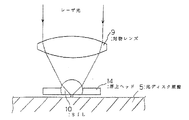
ところで、対物レンズによって集光されたレーザ光をさらに収束する方法としてソリッドイマージョンレンズ(SIL)を用いる方法が知られている。図6 は、対物レンズによって集光されたレーザ光がSILによってさらに収束される状態を示した図である。図示せぬ光源からのレーザ光は対物レンズ9で浮上ヘッド14に保持されたSIL10上に集光され、SIL10にて収束され光ディスク原盤5に照射される。なお、対物レンズ9とSIL10はそれぞれ独立に駆動できるように構成されている。SIL10により対物レンズ9の開口数を実質上あげることができ、その結果光ディスク原盤上に微小光スポットを形成することができる。
【0006】
対物レンズ及びSILを備えた光ヘッドを搭載した光ディスク原盤記録装置においては2種類のレンズが存在するので、対物レンズの中心位置がレーザ光のスポット位置あるいはSILの中心位置がレーザ光のスポット位置となるわけではない。つまり、対物レンズとSILの位置関係により光スポットの位置が変化してしまうため、従来のように対物レンズの中心位置を検出していただけでは光ディスク原盤上における光スポット位置を求めることができない。そのため、光スポットの位置を目標スポット位置になるように制御することができないという問題があった。
【0007】
本発明は上述の問題点に鑑みなされたものであり、光ヘッドに対物レンズ及びSILを搭載した場合でも、光スポット位置の制御を確実に行うことのできるディスク原盤記録装置を提供することを目的とする。
【0008】
【課題を解決するための手段】
請求項1記載の発明は、光ディスク原盤に照射される記録光を集光する対物レンズと、対物レンズにより集光された記録光をさらに収束するソリッドイマージョンレンズと、対物レンズを光ディスク原盤の半径方向に駆動させる第1の駆動手段と、ソリッドイマージョンレンズを光ディスク原盤の半径方向に駆動させる第2の駆動手段と、半径方向における基準位置からの対物レンズの中心位置を求める手段と、半径方向における基準位置からのソリッドイマージョンレンズの中心位置を求める手段と、対物レンズの中心位置及びソリッドイマージョンレンズの中心位置に基づいて、記録光の光ディスク原盤上におけるスポット位置を算出する手段と、算出されたスポット位置を目標スポット位置に近づけるべく第1及び第2の駆動手段を制御する制御手段と、から構成された光ディスク原盤記録装置であることを特徴とする。
【0009】
請求項2記載の発明は、請求項1記載の光ディスク原盤記録装置において、制御手段は、算出されたスポット位置と目標位置との差をトラッキングエラー信号とし、該トラッキングエラー信号に基づいて第1及び第2の駆動手段を制御することを特徴とする。
【0010】
請求項3記載の発明は、請求項2記載の光ディスク記録原盤記録装置におい て、制御手段は、トラッキングエラー信号の低域周波数成分に基づいて第2の駆動手段を制御することを特徴とする。
【0011】
【作用】
本発明は以上のように構成したので、記録時に対物レンズ及びソリッドイマージョンレンズがそれぞれ目標スポット位置からずれていても、制御手段が、対物レンズの中心位置L1 とソリッドイマージョンレンズの中心位置L2 に基づいて算出されたスポット位置Lを目標スポット位置に合わせるように第1及び第2の駆動手段を制御するので、光ディスク原盤上の光スポットの位置を目標スポット位置に確実に制御できる。
【0012】
【発明の実施の形態】
次に、本発明に好適な実施形態について図面に基づいて説明する。
【0013】
(1)第1の実施形態
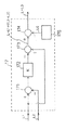
図1は、本発明の第1の実施形態における光ディスク原盤記録装置の光ヘッドの制御ブロック図である。
【0014】
筐体8を担持したキャリッジ2は、ローラガイド3を介して光ディスク原盤記録装置の基台4上に設けられており、係合する送りネジ6及びこれを回転するモータ7によって光ディスク原盤5の半径方向に移動自在駆動されるように構成されている。対物レンズ9は弾性体からなる支持部材11を介して筐体8に取り付けられ、アクチュエータ12によりトラッキング方向及びフォーカス方向に移動可能に浮遊保持されている。アクチュエータ12は、対物レンズ9をトラッキング方向及びフォーカス方向に駆動させるための駆動用コイルであり、アクチュエータドライバ13によって供給される駆動電流に応じて、対物レンズ9の光軸X1 をトラッキング方向に適宜平行移動させることができる。
【0015】
また、筐体8に取り付けられた浮上ヘッド14は、SIL10を保持するものであり、この浮上ヘッド14により、記録時において光ディスク原盤5とSIL10との間の距離は約50〜100nmとなる。なお、浮上ヘッド14として負圧ヘッドを用いることにより光ディスク原盤5とSIL10との間の距離を線速によらず一定に保つことができる。負圧ヘッドについては日経エレクトロニクスNo.528(1991・5・27発行)の110〜111頁に詳細に記載されている。
【0016】
モータ7を駆動し筐体8と共に浮上ヘッド14をトラッキング方向に適宜移動することにより、SIL10の光軸X2 をトラッキング方向に平行移動させることができる。
【0017】
測長器15は、光ディスク原盤5の半径方向における基準位置からの対物レンズ9の位置を光学的に求め、対物レンズ9の中心位置L1を算出し制御部17に出力する。測長器16は、光ディスク原盤5の半径方向における基準位置からのSIL10の位置を光学的に求め、SIL10の中心位置L2を算出し制御部17に出力する。対物レンズ9及びSIL10の位置を光学的に求める方法としては特開平3−150746号公報に記載されている方法等を用いることができ る。
【0018】
制御部17は対物レンズ9の中心位置L1とSIL10の中心位置L2とに基づいて光ディスク原盤上のレーザ光のスポット位置Lを算出する。そして、この算出されたスポット位置Lと目標スポット位置L0とのずれ量を示すトラキングエラー信号(L−L0)を出力する。なお、制御部17の具体的な構成については後述する。
【0019】
制御部17で生成したトラッキングエラー信号は低域通過フィルタ(LPF)19に供給される。LPF19を通過したトラッキングエラー信号の低域周波数成分をイコライザ20で波形整形したのちモータドライバ21に供給される。モータドライバ21では供給されるトラッキングエラー信号に基づきモータ7を駆動するための駆動信号を出力する。よって、モータ7及び送りネジ6が回転することにより、筐体8に取り付けられた浮上ヘッド14に搭載されたSIL10をトラッキング方向に移動させてSIL10の光軸X2のトラッキング調整が行われる。
【0020】
また、制御部17で生成したトラッキングエラー信号はイコライザ18にも供給される。イコライザ18で波形整形されたトラッキングエラー信号はアクチュエータドライバ13に供給される。そしてアクチュエータドライバ13から出力される駆動信号をアクチュエータ12に供給することにより、対物レンズ9をトラッキング方向に移動させて対物レンズ9の光軸X1のトラッキング調整を行う。この場合、制御手段がトラッキングエラー信号の低域周波数成分に基づいて算出されたスポット位置Lを目標スポット位置L0へ近づけるようにSIL10をトラッキング方向に移動することになる。これは、SIL10を移動させるためのキャリッジ2の質量が大きく高帯域の駆動信号には応答できないからである。
【0021】
以上のように、第1の実施形態における光ディスク原盤記録装置は、制御手段が算出されたスポット位置Lと目標スポット位置L0によってトラッキングエラー信号(L−L0)を生成し、これに基づいてトラッキング方向における対物レンズ9の光軸X1及びSIL10の光軸X2を独立に移動させ、トラッキングエラー信号(L−L0)が0となるように、つまり算出されたスポット位置Lが目標スポット位置L0に移動するように制御される。よって、レーザ光のスポット位置を正確に制御することが可能になる。
【0022】
図2は制御部17の構成を示した図である。制御部17は、測長器15の出力L1と測長器16の出力L2との減算を行う減算器171、ゲイン調整器17 2、加算器173、減算器174及び目標スポット位置を出力する目標スポット位置算出手段175を備えている。
【0023】
次に、制御手段の具体的制御動作について説明する。
図1において、測長器15で算出された対物レンズ9の中心位置L1は減算器171及び加算器173に供給される。測長器16で算出されたSIL10の中心位置L2は減算器171に供給される。
【0024】
減算器171はL1からL2を減算し(L1−L2)をゲイン調整器172に出力する。ゲイン調整器172はこれをK倍し加算器173に出力する。ここでKは、光ヘッド1に用いられる対物レンズ9とSIL10の光学的性質により適宜設定される定数(0<K<1)である。例えば、nをSIL10の屈折率とすると、K = 1−1/ n 、K = 1−1/ n2 等を用いることができ る。
【0025】
図3は、対物レンズ9の光軸X1とSIL10の光軸X2の位置関係を示した図である。図3に示すように、トラッキング方向における基準位置から対物レンズ9の光軸X1までの距離がL1であり、トラッキング方向における基準位置からSIL10の光軸X2 までの距離がL2である。したがってSIL10の光軸X2は対物レンズ9の光軸X2に対し(L1−L2)だけずれた位置にある。
【0026】
この場合に対物レンズ9とSIL10によって収束されるレーザ光の光ディスク原盤上におけるスポット位置Lは前述のKを用いると、
L = L1 + K(L1−L2) で表される。
【0027】
制御部17では光スポット位置Lを求めるために、測長器15で算出されたL1及び測長器16で算出されたL2を用いて、ゲイン調整器172にてK(L1−L2)を生成し加算器173に出力し、加算器173にてK(L1−L2)と測長器15からのL1とを加算することを行っている。加算器173の出力は減算器174に供給されトラッキングエラー信号の生成に用いられる。減算器174には加算器173の出力と目標スポット位置算出手段175からの出力である目標スポット位置L0が供給されている。目標スポット位置L0は記録が進むに連れ逐次更新されるものである。減算器174は、加算器173によって算出されたスポット位置Lから目標スポット位置L0を減算することによってトラッキングエラー信号(L−L0)を生成し、イコライザ18及びLPF19に出力する。
【0028】
よって、制御部17で出力されたトラッキングエラー信号に基づき対物レンズ9及びSIL10をトラッキング方向に移動させることにより、レーザ光のスポット位置が目標スポット位置となるように制御することができる。
【0029】
(2)第2の実施形態
以下の第2の実施形態に示すように、対物レンズ9の中心位置L1を求める測長器15の代りに、SIL10の中心位置L2に対する対物レンズ9の中心位置L1のずれ量、つまりL1−L2を求める測長器22を設けて、これと測長器16の出力L2に基づいてトラッキングエラー信号(L−L0)を生成するように構成しても良い。
【0030】
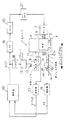
図4は本発明の第2の実施形態における光ディスク原盤記録装置の光ヘッドの制御ブロック図である。同図において、第1の実施形態と同じ構成部分については、図1と同一の符号を付してあり説明を省略する。
【0031】
図4において、測長器22はSIL10の中心位置L2に対する対物レンズ9の中心位置L1のずれ量、つまりL1−L2を光学的に求め制御部30に出力する。また測長器16は、光ディスク原盤5の半径方向における基準位置からのSIL10の位置を光学的に求め、SIL10の中心位置L2を算出し制御部30に出力する。測長器22はピエゾ素子などを用いて対物レンズ9の変位量を検出しこの変位量からずれ量としてL1−L2を求める。
【0032】
制御部30は測長器22から出力されるL1−L2と測長器16から出力されるL2に基づいて光ディスク原盤上のレーザ光のスポット位置Lを算出する。そして、この算出されたスポット位置Lと目標スポット位置L0とのずれ量を示すトラキングエラー信号(L−L0)を出力する。制御部30で生成したトラッキングエラー信号はイコライザ18及びLPF19に供給されその後の制御動作が先の第1の実施形態と同様に行われ、算出されたスポット位置Lが目標スポット位置L0に移動するように制御される。よって、レーザ光のスポット位置を正確に制御することが可能になる。
【0033】
図5は制御部30の構成を示した図である。制御部30は、測長器22の出力(L1−L2)が供給されるゲイン調整器301、ゲイン調整器301の出力と測長器16の出力L2とを加算する加算器302、減算器303、目標スポット位置算出手段175を備えている。
【0034】
次に、制御手段の具体的制御動作について説明する。
図5において、測長器22で求められた(L1−L2)はゲイン調整器301に供給される。ゲイン調整器301はこれをK´倍してK´(L1−L2)を生成し加算器302に出力する。ここでK´は、上述したKと同じく光ヘッド1に用いられる対物レンズ9とSIL10の光学的性質により適宜設定される定数(0<K´<1)である。
【0035】
図3において、対物レンズ9とSIL10によって収束される光ディスク原盤上におけるレーザ光のスポット位置LはSIL10の光軸X2に対し、対物レンズ9がずれた方向と反対方向にずれ、光軸X2からのずれ量は光軸X2に対するX1のずれ量に概ね比例する。したがって、この比例定数をK´として現在のスポット位置Lを算出すると、L = L2+K´(L1−L2)で表される。
【0036】
したがって、上述したようにゲイン調整器301は、K´(L1−L2)を生成し加算器302に出力し、加算器302は、このK´(L1−L2)と測長器16からのL2 とを加算し、加算結果を現在の記録光の光ディスク原盤上におけるスポット位置L(L=L2+K´(L1−L2))、つまり現在の対物レンズ9とSIL10の各光軸によって収束される記録光のスポットの上記基準位置からのずれ量として算出する。
【0037】
加算器302の出力は減算器303に供給されトラッキングエラー信号の生成に用いられる。減算器303には加算器302の出力と目標スポット位置算出手段175からの出力である目標スポット位置L0が供給されている。減算器303は、加算器302によって算出されたスポット位置Lから目標スポット位置L0を減算することによってトラッキングエラー信号(L−L0)を生成し、イコライザ18及びLPF19に出力する。
【0038】
よって、制御部30で出力されたトラッキングエラー信号に基づき対物レンズ9及びSIL10をトラッキング方向に移動させることにより、レーザ光のスポット位置が目標スポット位置となるように制御することができる。
【0039】
なお、上述した各実施形態においては、対物レンズ9をトラッキングの微調整に用い、SIL10にトラッキングエラー信号の低周波成分によるトラッキングの粗調整に用いた場合で説明したが、本発明はこれに限らず、対物レンズ9をトラッキングの粗調整に用い、SIL10をトラッキングの微調整に用いるように構成しても良い。
【0040】
【発明の効果】
本発明は以上のように構成したため、記録時に対物レンズ及びソリッドイマージョンレンズがそれぞれ目標スポット位置L0からずれていても、制御手段が、対物レンズの中心位置L1とソリッドイマージョンレンズの中心位置L2に基づいて算出されたスポット位置Lを目標スポット位置L0に合わせるように第1及び第2の駆動手段を制御するので、対物レンズによって収束されさらにソリッドイマージョンレンズによって収束される記録光は、正確に光ディスク原盤上の目標スポット位置L0に追従して光スポットを形成することができる。
【図面の簡単な説明】
【図1】本発明の第1の実施形態における光ディスク原盤記録装置の光ヘッドの制御ブロック図である。
【図2】第1の実施形態における光ディスク原盤記録装置の制御部の構成を示した図である。
【図3】対物レンズの光軸X1 とSILの光軸X2 の互いの位置関係を示した図であ る。
【図4】本発明の第2の実施形態における光ディスク原盤記録装置の光ヘッドの制御ブロック図である。
【図5】第2の実施形態における光ディスク原盤記録装置の制御部の構成を示した図である。
【図6】対物レンズによって集光されたレーザ光がSILによってさらに収束される状態を示した図である。
【符号の説明】
1・・・・・光ヘッド
2・・・・・キャリッジ
3・・・・・ローラガイド
4・・・・・基台
5・・・・・光ディスク原盤
6・・・・・送りネジ
7・・・・・モータ
8・・・・・筐体
9・・・・・対物レンズ
10・・・・ソリッドイマージョンレンズ(SIL)
11・・・・支持部材
12・・・・アクチュエータ
13・・・・アクチュエータドライバ
14・・・・浮上ヘッド
15、16、22・・・・測長器
17、30・・・・制御部
18、20・・・・イコライザ
19・・・・低域通過フィルタ(LPF)
21・・・・モータドライバ
171、174、303・・・・減算器
172、301・・・・ゲイン調整器
173、302・・・・加算器
175・・・・・目標スポット位置算出手段[0001]
BACKGROUND OF THE INVENTION
The present invention relates to an optical disc master recording apparatus used for making an optical disc master.
[0002]
[Prior art]
2. Description of the Related Art Conventionally, an optical disc master recording apparatus used for creating an optical disc master such as a compact disc (CD) or a laser disc (LD) is known. These optical disc master recording devices control the rotation of an optical disc master in which a photoresist film is formed on a glass plate whose surface has been polished so that it has a predetermined speed, and the laser beam condensed by the objective lens of the optical head Information is recorded on the optical disk master in a spiral manner by sequentially controlling the feeding in the radial direction of the optical disk master.
[0003]
In order to control the spot position of the laser beam to coincide with the target spot position, the entire optical head is driven in the radial direction of the optical disk master and coarsely adjusted, and the objective lens is driven in the radial direction by an actuator in the optical head. This is done by making fine adjustments. In this case, since the center position of the objective lens becomes the spot position of the laser beam, the center position of the objective lens is detected and the deviation between the center position of the objective lens and the target spot position is performed in order to perform the above coarse adjustment and fine adjustment. Control is performed to drive the optical head and actuator so that the amount is eliminated.
[0004]
[Problems to be solved by the invention]
In recent years, in order to dramatically improve the recording density of an optical disc, information must be recorded with a much smaller track pitch and pits than in the past. However, there is a limit to forming a light spot that is dramatically smaller than the present with only the objective lens.
[0005]
By the way, a method using a solid immersion lens (SIL) is known as a method for further converging the laser beam condensed by the objective lens. FIG. 6 is a diagram showing a state in which the laser beam condensed by the objective lens is further converged by the SIL. Laser light from a light source (not shown) is condensed on the
[0006]
In an optical disc master recording apparatus equipped with an objective lens and an optical head equipped with an SIL, there are two types of lenses. Therefore, the center position of the objective lens is the spot position of the laser beam or the center position of the SIL is the spot position of the laser beam. It doesn't mean. In other words, since the position of the light spot changes depending on the positional relationship between the objective lens and the SIL, the position of the light spot on the optical disc master cannot be obtained only by detecting the center position of the objective lens as in the prior art. For this reason, there is a problem that the position of the light spot cannot be controlled to be the target spot position.
[0007]
The present invention has been made in view of the above-described problems, and an object of the present invention is to provide a master disk recording apparatus capable of reliably controlling the light spot position even when the objective lens and the SIL are mounted on the optical head. And
[0008]
[Means for Solving the Problems]
According to the first aspect of the present invention, there is provided an objective lens for condensing recording light irradiated on the optical disc master, a solid immersion lens for further converging the recording light condensed by the objective lens, and the objective lens in the radial direction of the optical disc master. First driving means for driving the optical disk, second driving means for driving the solid immersion lens in the radial direction of the master optical disc, means for determining the center position of the objective lens from the reference position in the radial direction, and reference in the radial direction Means for determining the center position of the solid immersion lens from the position, means for calculating the spot position of the recording light on the optical disk master based on the center position of the objective lens and the center position of the solid immersion lens, and the calculated spot position The first and second driving means are controlled so as to bring the target spot position closer to the target spot position. Characterized in that a control means for a master optical disc recording apparatus which is constructed from.
[0009]
According to a second aspect of the present invention, in the optical disk master recording apparatus according to the first aspect, the control means uses the difference between the calculated spot position and the target position as a tracking error signal, and the first and the second based on the tracking error signal. The second drive means is controlled.
[0010]
According to a third aspect of the present invention, in the optical disk recording master recording apparatus according to the second aspect, the control means controls the second driving means based on the low frequency component of the tracking error signal.
[0011]
[Action]
Since the present invention is configured as described above, even if the objective lens and the solid immersion lens are displaced from the target spot position at the time of recording, the control means is based on the center position L1 of the objective lens and the center position L2 of the solid immersion lens. Since the first and second driving means are controlled so that the calculated spot position L matches the target spot position, the position of the light spot on the optical disc master can be reliably controlled to the target spot position.
[0012]
DETAILED DESCRIPTION OF THE INVENTION
Next, preferred embodiments of the present invention will be described with reference to the drawings.
[0013]
(1) First Embodiment FIG. 1 is a control block diagram of an optical head of an optical disk master recording apparatus according to a first embodiment of the present invention.
[0014]
The carriage 2 carrying the
[0015]
The
[0016]
By driving the
[0017]
The
[0018]
The
[0019]
The tracking error signal generated by the
[0020]
The tracking error signal generated by the
[0021]
As described above, the optical disc master recording apparatus according to the first embodiment generates the tracking error signal (L-L0) based on the spot position L and the target spot position L0 calculated by the control unit, and based on this, the tracking direction The optical axis X1 of the
[0022]
FIG. 2 is a diagram showing the configuration of the
[0023]
Next, a specific control operation of the control means will be described.
In FIG. 1, the
[0024]
The
[0025]
FIG. 3 is a diagram showing the positional relationship between the optical axis X1 of the
[0026]
In this case, if the above-mentioned K is used as the spot position L on the optical disk master of the laser beam converged by the
L = L1 + K (L1-L2)
[0027]
In order to obtain the light spot position L in the
[0028]
Therefore, by moving the
[0029]
(2) Second Embodiment As shown in the following second embodiment, instead of the
[0030]
FIG. 4 is a control block diagram of the optical head of the optical disk master recording apparatus according to the second embodiment of the present invention. In the figure, the same components as those in the first embodiment are denoted by the same reference numerals as those in FIG.
[0031]
In FIG. 4, the
[0032]
The
[0033]
FIG. 5 is a diagram illustrating a configuration of the
[0034]
Next, a specific control operation of the control means will be described.
In FIG. 5, (L1−L2) obtained by the
[0035]
In FIG. 3, the spot position L of the laser beam on the optical disc master converged by the
[0036]
Therefore, as described above, the
[0037]
The output of the
[0038]
Therefore, by moving the
[0039]
In each of the above-described embodiments, the
[0040]
【The invention's effect】
Since the present invention is configured as described above, even if the objective lens and the solid immersion lens are displaced from the target spot position L0 during recording, the control means is based on the central position L1 of the objective lens and the central position L2 of the solid immersion lens. Since the first and second driving means are controlled so that the calculated spot position L matches the target spot position L0, the recording light converged by the objective lens and further converged by the solid immersion lens is accurately recorded on the optical disc master. A light spot can be formed following the upper target spot position L0.
[Brief description of the drawings]
FIG. 1 is a control block diagram of an optical head of an optical disc master recording apparatus according to a first embodiment of the present invention.
FIG. 2 is a diagram illustrating a configuration of a control unit of the optical disc master recording apparatus according to the first embodiment.
FIG. 3 is a diagram showing the positional relationship between the optical axis X1 of the objective lens and the optical axis X2 of the SIL.
FIG. 4 is a control block diagram of an optical head of an optical disc master recording apparatus according to a second embodiment of the present invention.
FIG. 5 is a diagram illustrating a configuration of a control unit of an optical disc master recording apparatus according to a second embodiment.
FIG. 6 is a diagram showing a state in which laser light focused by an objective lens is further converged by SIL.
[Explanation of symbols]
DESCRIPTION OF
11...
21 ...
Claims (3)
前記対物レンズを前記光ディスク原盤の半径方向に駆動させる第1の駆動手段と、
前記ソリッドイマージョンレンズを前記光ディスク原盤の半径方向に駆動させる第2の駆動手段と、
前記半径方向における基準位置からの前記対物レンズの中心位置を求める手段と、
前記半径方向における基準位置からの前記ソリッドイマージョンレンズの中心位置を求める手段と、
前記対物レンズの中心位置及び前記ソリッドイマージョンレンズの中心位置に基づいて、前記記録光の前記光ディスク原盤上におけるスポット位置を算出する手段と、
算出されたスポット位置を目標スポット位置に近づけるべく前記第1及び第2の駆動手段を制御する制御手段と、
を備えたことを特徴とする光ディスク原盤記録装置。An objective lens for condensing recording light applied to the optical disc master, and a solid immersion lens for further converging the recording light condensed by the objective lens,
First driving means for driving the objective lens in a radial direction of the optical disc master;
Second driving means for driving the solid immersion lens in a radial direction of the optical disc master;
Means for determining a center position of the objective lens from a reference position in the radial direction;
Means for determining a center position of the solid immersion lens from a reference position in the radial direction;
Means for calculating a spot position of the recording light on the optical disc master based on the center position of the objective lens and the center position of the solid immersion lens;
Control means for controlling the first and second driving means to bring the calculated spot position closer to the target spot position;
An optical disc master recording apparatus comprising:
Priority Applications (2)
| Application Number | Priority Date | Filing Date | Title |
|---|---|---|---|
| JP10401098A JP3642947B2 (en) | 1998-03-31 | 1998-03-31 | Optical disc master recording device |
| US09/280,563 US6226238B1 (en) | 1998-03-31 | 1999-03-30 | Optical disc master recording device |
Applications Claiming Priority (1)
| Application Number | Priority Date | Filing Date | Title |
|---|---|---|---|
| JP10401098A JP3642947B2 (en) | 1998-03-31 | 1998-03-31 | Optical disc master recording device |
Publications (2)
| Publication Number | Publication Date |
|---|---|
| JPH11288523A JPH11288523A (en) | 1999-10-19 |
| JP3642947B2 true JP3642947B2 (en) | 2005-04-27 |
Family
ID=14369306
Family Applications (1)
| Application Number | Title | Priority Date | Filing Date |
|---|---|---|---|
| JP10401098A Expired - Fee Related JP3642947B2 (en) | 1998-03-31 | 1998-03-31 | Optical disc master recording device |
Country Status (2)
| Country | Link |
|---|---|
| US (1) | US6226238B1 (en) |
| JP (1) | JP3642947B2 (en) |
Families Citing this family (7)
| Publication number | Priority date | Publication date | Assignee | Title |
|---|---|---|---|---|
| SG97826A1 (en) * | 2000-01-07 | 2003-08-20 | Inst Data Storage | Optical recording system with aspherical solid immersion lens |
| KR100319459B1 (en) * | 2000-01-28 | 2002-01-09 | 오길록 | Tracking method for high density near-field optical data storage and apparatus for the same |
| KR100370016B1 (en) * | 2000-06-02 | 2003-01-29 | 엘지전자 주식회사 | optical information record micro mirror and method for fabricating the same and method for optical pick up apparatus using the same |
| KR100392633B1 (en) | 2000-12-19 | 2003-07-23 | 삼성전자주식회사 | Optical pick-up apparatus for optical disk drive |
| JP4567594B2 (en) * | 2003-03-20 | 2010-10-20 | 浜松ホトニクス株式会社 | Microscope, sample observation method, and semiconductor inspection method |
| US7110172B2 (en) * | 2004-02-27 | 2006-09-19 | Hamamatsu Photonics K.K. | Microscope and sample observation method |
| KR100629996B1 (en) * | 2004-12-27 | 2006-09-27 | 엘지전자 주식회사 | Apparatus and method for optical recording and reading of a different kind |
Family Cites Families (2)
| Publication number | Priority date | Publication date | Assignee | Title |
|---|---|---|---|---|
| US5729393A (en) * | 1996-04-03 | 1998-03-17 | Digital Papyrus Corporation | Optical flying head with solid immersion lens having raised central surface facing medium |
| US6101155A (en) * | 1997-08-14 | 2000-08-08 | Seagate Technology, Inc. | Lens for optical data storage system |
-
1998
- 1998-03-31 JP JP10401098A patent/JP3642947B2/en not_active Expired - Fee Related
-
1999
- 1999-03-30 US US09/280,563 patent/US6226238B1/en not_active Expired - Fee Related
Also Published As
| Publication number | Publication date |
|---|---|
| JPH11288523A (en) | 1999-10-19 |
| US6226238B1 (en) | 2001-05-01 |
Similar Documents
| Publication | Publication Date | Title |
|---|---|---|
| JP2666248B2 (en) | Optical information recording / reproducing device | |
| US4614863A (en) | Optical signal processing system with variable gain stage of servo system controlled by output of environmental condition sensor | |
| EP0367094B1 (en) | Optical disk apparatus | |
| JP3642947B2 (en) | Optical disc master recording device | |
| KR100523522B1 (en) | Optical disc recording and reproducing apparatus and method | |
| US6272079B1 (en) | Optical head unit for optical disk apparatus having both focus control and track control function | |
| JPH04245034A (en) | Optical head device | |
| JP3903576B2 (en) | Optical disc apparatus and distance detection apparatus and detection method used therefor | |
| JP4123464B2 (en) | Optical recording / reproducing apparatus control method and optical recording / reproducing apparatus | |
| JP4060453B2 (en) | Optical storage device and method for adjusting positioner drive sensitivity | |
| US20070280064A1 (en) | Optical disk device | |
| JP3607670B2 (en) | Optical disc apparatus and disc tilt detection method | |
| JPH0435830B2 (en) | ||
| JP2970787B2 (en) | Objective lens control system | |
| JPH0980298A (en) | Focusing control method and device therefor, and recorder for optical disk original recording | |
| JP2783873B2 (en) | Separate optical head | |
| JPH11144280A (en) | Optical disk device | |
| JP3930128B2 (en) | Servo circuit | |
| JPH11144293A (en) | Optical head and optical recorder | |
| JP2748900B2 (en) | Exposure equipment | |
| JPH05325305A (en) | Controller for position of magnetic head | |
| JPH08329476A (en) | Optical master disk exposure device and its control method | |
| KR19980068254A (en) | Position control method of an objective lens, a device suitable for the same, and a tracking servo device using the same | |
| JP2000099970A (en) | Optical disk device | |
| JPH09204672A (en) | Optical pickup driving method and optical disc driver |
Legal Events
| Date | Code | Title | Description |
|---|---|---|---|
| A521 | Request for written amendment filed |
Free format text: JAPANESE INTERMEDIATE CODE: A523 Effective date: 20040427 |
|
| A621 | Written request for application examination |
Free format text: JAPANESE INTERMEDIATE CODE: A621 Effective date: 20040427 |
|
| A977 | Report on retrieval |
Free format text: JAPANESE INTERMEDIATE CODE: A971007 Effective date: 20050107 |
|
| TRDD | Decision of grant or rejection written | ||
| A01 | Written decision to grant a patent or to grant a registration (utility model) |
Free format text: JAPANESE INTERMEDIATE CODE: A01 Effective date: 20050118 |
|
| A61 | First payment of annual fees (during grant procedure) |
Free format text: JAPANESE INTERMEDIATE CODE: A61 Effective date: 20050126 |
|
| R150 | Certificate of patent or registration of utility model |
Free format text: JAPANESE INTERMEDIATE CODE: R150 |
|
| FPAY | Renewal fee payment (event date is renewal date of database) |
Free format text: PAYMENT UNTIL: 20090204 Year of fee payment: 4 |
|
| FPAY | Renewal fee payment (event date is renewal date of database) |
Free format text: PAYMENT UNTIL: 20100204 Year of fee payment: 5 |
|
| FPAY | Renewal fee payment (event date is renewal date of database) |
Free format text: PAYMENT UNTIL: 20110204 Year of fee payment: 6 |
|
| FPAY | Renewal fee payment (event date is renewal date of database) |
Free format text: PAYMENT UNTIL: 20110204 Year of fee payment: 6 |
|
| FPAY | Renewal fee payment (event date is renewal date of database) |
Free format text: PAYMENT UNTIL: 20120204 Year of fee payment: 7 |
|
| FPAY | Renewal fee payment (event date is renewal date of database) |
Free format text: PAYMENT UNTIL: 20130204 Year of fee payment: 8 |
|
| LAPS | Cancellation because of no payment of annual fees |