JP3641027B2 - Electric power steering device - Google Patents
Electric power steering device Download PDFInfo
- Publication number
- JP3641027B2 JP3641027B2 JP21958495A JP21958495A JP3641027B2 JP 3641027 B2 JP3641027 B2 JP 3641027B2 JP 21958495 A JP21958495 A JP 21958495A JP 21958495 A JP21958495 A JP 21958495A JP 3641027 B2 JP3641027 B2 JP 3641027B2
- Authority
- JP
- Japan
- Prior art keywords
- frequency
- alternator
- voltage
- pulsation
- pass filter
- Prior art date
- Legal status (The legal status is an assumption and is not a legal conclusion. Google has not performed a legal analysis and makes no representation as to the accuracy of the status listed.)
- Expired - Fee Related
Links
Images


Description
【0001】
【発明の属する技術分野】
この発明は、オルタネータの脈動周波数からエンジン回転数を算出する電動式パワーステアリング装置に関する。
【0002】
【従来の技術】
図5、6に示す従来例の電動パワーステリング装置では、アシスト力を付与するための電動モータmが、コントローラーCを介して、バッテリBに接続している。
上記バッテリBには、オルタネータ1を接続している。オルタネータ1は、図示しないエンジンに連動して駆動し、交流電圧を発電する。そして、この交流電圧を整流して、バッテリBに蓄電させるものである。
このオルタネータ1には、オルタネータの1の発電量を調節するレギュレータ1aが組み込まれている。つまり、バッテリ電圧が上昇すると、レギュレータ1aがオルタネータ1の発電を停止させ、反対に、バッテリ電圧が降下すると、レギュレータ1aがオルタネータ1に発電を開始させる。このようにしてレギュレータ1aがオルタネータ1をオン・オフ調整し、バッテリBの蓄電量を一定に保っている。
【0003】
また、上記コントローラーCは、電動モータmを制御するためのもので、電動モータmに電圧を印加する駆動回路2、この駆動回路2をPWM制御する制御回路3、及びコントローラーCに電源電圧を印加する電源回路4などから構成されている。
上記駆動回路2は、主にモータ駆動素子から構成されている。そして、これらモータ駆動素子は、車両の走行状態に応じて制御回路3によりPWM制御され、電動モータmを正転あるいは逆転させる。このようにして電動モータmが駆動すると、その出力が図示しない操舵機構に伝えられ、操舵をアシストすることになる。
【0004】
さらに、このコントローラーCには、オルタネータ脈動検出回路5を設けている。そして、次のようにして、エンジン回転数Nを算出している。
電動式パワーステアリング装置の電源電圧Vには、オルタネータ1の発電交流電圧を整流した電圧が重畳している。
ここで、オルタネータ1はエンジンにより駆動するため、オルタネータ1の発電した交流電圧は、エンジン回転Nの脈動に比例した脈動周波数を有する。したがって、この交流電圧を整流した電圧の脈動周波数も、エンジン回転数Nに比例することになる。
つまり、図6に示すように、電源電圧Vは、オルタネータ1の脈動周波数と同じ脈動周波数を有することになる。したがって、この電源電圧Vの脈動周波数をオルタネータ脈動検出回路5で検出すれば、オルタネータ1の脈動周波数Fを知ることができる。そして、オルタネータの脈動周波数Fを知ることができれば、エンジン回転数Nを算出できる。
【0005】
このようにしてエンジン回転数Nを算出できれば、例えば、制御回路3が電源回路4を制御し、必要なときにだけコントローラーCに主電源を印加させることができる。つまり、算出したエンジン回転数Nが設定値よりも大きければ、制御回路3が電源回路4を動作させて、主電圧をコントローラーCに印加させる。それに対し、エンジン回転数Nが設定値以下であれば、制御回路3はシステムを起動する必要が無いと判断し、電源回路4を動作させて、バックアップ電圧のみをコントローラーCに印加させる。
このようにすれば、コントローラーCのオン・オフを、外部のイグニションスイッチIGに連動させる必要がなくなり、外部配線を少なくできる。そして、外部配線を少なくできれば、それだけ電動式パワーステアリング装置のコストダウン及び小型化が可能となる。
また、エンジン回転数Nは車速とほぼ比例するので、エンジン回転数Nが分かれば、車速を推定することもできる。したがって、車速を検出する必要な場合にも、車速センサを設ける必要がなく、コストダウン及び小型化が可能となる。
【0006】
【発明が解決しようとする課題】
しかしながら、上記従来例における電動式パワーステアリング装置では、エンジン回転数Nを正確に算出できないことがあった。
その第1の理由は、オルタネータ1がレギュレータ1aによりオン・オフ調整されているからである。つまり、このオン・オフが繰り返されると、オルタネータ1が発電・停止を繰り返し、その電圧変動が電源電圧Vに重畳してしまう。そのため、電源電圧Vの脈動周波数に、オン・オフによる電圧変動の脈動周波数が混ざってしまい、オルタネータ1の脈動周波数Fを正確に検出することができなかった。
第2の理由は、駆動回路5のモータ駆動素子が、制御回路3によりPWM制御されているからである。つまり、モータ駆動素子がPWM制御されると、その電圧変動が電源電圧Vにも重畳してしまう。そのため、電源電圧Vの脈動周波数に、PWM制御による電圧変動の脈動周波数が混ざってしまい、オルタネータ1の脈動周波数Fを正確に検出することができなかった。
【0007】
第3の理由は、バッテリBには、この電動式パワーステアリング装置以外にも、他の電気負荷6を接続しているからである。つまり、例えば、他の電気負荷6を停止・起動させると電圧変動が生じてしまい、その電圧変動が電源電圧Vに重畳してしまう。そのため、電源電圧Vの脈動周波数に、他の電気負荷6で発生した電圧変動の脈動周波数が混ざってしまい、オルタネータ1の脈動周波数Fを正確に検出することができなかった。
この発明の目的は、正確にオルタネータの脈動周波数を検出し、正確なエンジン回転数を算出できる電動式パワーステアリング装置を提供することである。
【0008】
【課題を解決するための手段】
この発明は、操舵アシスト力を付与する電動モータと、電動モータを制御するコントローラーと、コントローラーに接続したバッテリと、エンジンに連係するオルタネータと、このオルタネータを調整するレギュレータとを備え、しかも、上記コントローラーは、電動モータに電圧を印加する駆動回路と、電源電圧の脈動周波数からオルタネータの脈動周波数を検出するオルタネータ脈動検出回路と、駆動回路をPWM制御する一方、オルタネータの脈動周波数からエンジン回転数を算出する制御回路とからなる電動式パワーステアリング装置を前提とする。
そして、第1の発明は、所定の周波数範囲における脈動電圧のみをオルタネータ脈動検出回路に伝えるフィルターを設け、フィルターは、設定した周波数よりも高い周波数の脈動電圧を伝えるハイパスフィルターと、設定した周波数よりも低い周波数の脈動電圧を伝えるローパスフィルターとからなり、しかも、レギュレータの調整による電圧変動の脈動周波数をハイパスフィルターの設定周波数よりも低く、また、PWM制御による電圧変動の脈動周波数をローパスフィルターの設定周波数よりも高くした点に特徴を有する。
【0009】
このような構成にしたので、電源電圧の脈動周波数のうち、設定した範囲の外にある脈動電圧はフィルターにより減衰させることができる。特に、オルタネータのオン・オフ調整による脈動電圧や、PWM制御による脈動電圧を減衰させることができる。
つまり、レギュレータのオン・オフ調整による電圧変動の脈動周波数は、オルタネータの脈動周波数よりも低くしているので、その脈動電圧をハイパスフィルターにより減衰させることができる。なお、この脈動周波数は、オルタネータの特性、例えばオルタネータの極数等を変更したり、レギュレータやバッテリの特性を変更したりすることで、ある程度任意に設定できる。
それに対し、駆動回路のPWM制御による電圧変動の脈動周波数は、オルタネータの脈動周波数よりも高くしているので、その脈動電圧をローパスフィルターにより減衰させることができる。なお、この脈動周波数は、駆動回路の設計などにより、ある程度任意に設定できる。
もちろん、これら以外にも、設定範囲外にある周波数を有する脈動電圧を減衰させられるので、例えば、他の電気負荷による電圧変動の脈動周波数による影響を小さくすることができる。
【0010】
第2の発明は、第1の発明において、フィルターを通過した脈動電圧を所定の基準電圧と比較し、矩形波に変換するコンパレータを設け、オルタネータ脈動検出回路は、この矩形波の周期から、オルタネータの脈動周波数を検出する構成とした点に特徴を有する。
このような構成にしたので、矩形波に変換してから周波数を検出でき、容易に、しかも、正確に周波数を測定できる。
また、基準電圧の設定しだいでは、細かなノイズによる影響をなくすことができる。例えば、電源電圧を、高い基準電圧VH と低い基準電圧VL との2種類で比較すれば、これらVH −VL よりも小さなノイズは矩形波に現れない。
【0011】
【発明の実施の形態】
図1〜4に示すこの発明の実施の形態では、オルタネータ1とオルタネータ脈動検出回路5との間に、ハイパスフィルター7、ローパスフィルター8、及びコンパレータ9を設けている。そして、それ以外の構成については従来例の電動式パワーステアリング装置と同じであり、その詳細な説明を省略する。
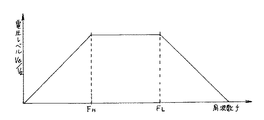
ハイパスフィルター7は、設定周波数FHよりも高い周波数を有する脈動電圧のみを伝えるものである。それに対し、ローパスフィルター8は、設定周波数FLよりも低い周波数を有する脈動電圧のみを伝えるものである。したがって、これらハイパスフィルター7とローパスフィルター8とによって、オルタネータ脈動検出回路5側に伝えられる脈動電圧は、周波数FH〜FLの範囲のものに限られることになる。
図2に、フィルター7、8による周波数特性を示す。この図2からも分かるように、脈動電圧の周波数が周波数FH〜FLの範囲にあれば、減衰することなくフィルター7、8を通過する。それに対し、脈動電圧の周波数が、周波数FH〜FLの範囲外にあると、フィルター7、8により減衰させられる。
なお、図2の縦軸で、Vaはフィルター7、8を通過する前の電源電圧あり、また、Vbはフィルター7、8を通過した後の電源電圧である。
【0012】
ここで、オルタネータ1の脈動周波数Fとエンジン回転数Nとの間には、次式(1)の関係がある。
F=(k×N×a)/60 ・・・(1)
ただし、F:オルタネータの脈動周波数(HZ)
k:オルタネータの極数 (オルタネータの一回転で発生する脈動)
N:エンジン回転数(rpm)
a:プーリ比 (オルタネータ回転数/エンジン回転数)
オルタネータの極数kやプーリ比aは、車種などにより異なるが、あらかじめ知ることができる数値である。また、エンジン回転数Nについても、車種などにより異なるが、実用されうるエンジン回転数Nの範囲をあらかじめ知ることができる。
したがって、オルタネータの脈動周波数Fがとりうる範囲は、式(1)から予測することができる。
【0013】
例えば、オルタネータ1の脈動周波数Fが、F0〜F1の範囲で変化すると予想できたとする。
このとき、ハイパスフィルター7の設定周波数FHを、予想される最低周波数F0よりやや小さく設定する。また、ローパスフィルター8の設定周波数FLを、予想される最低周波数F0よりやや大きく設定する。
このようにして設定周波数FH、FLを決めれば、電源電圧Vに含まれている脈動電圧のうちオルタネータ1の脈動電圧が、フィルター7、8を通過してオルタネータ脈動検出回路5側に伝えられる。しかも、周波数FH〜FLの範囲の外にある脈動を有する脈動電圧は、フィルター7、8により減衰させることができる。
【0014】
なお、フィルター7、8を通過した電源電圧Vは、コンパレータ9で所定の基準電圧と比較される。そして、矩形波に変換されてから、オルタネータ脈動検出回路5に伝えられる。
このようにして矩形波に変換されたら、オルタネータ脈動検出回路5が、この矩形波の周波数を周波数測定などの方法により検出する。さらに、この周期をオルタネータ1の脈動周波数Fの周期とみなして、制御回路3に出力する。
そして、制御回路3で、この検出されたオルタネータの脈動周波数Fと、あらかじめ分かっているオルタネータの極数k及びプーリ比aとを、
N=60×F/(k×a)
に代入し、エンジン回転数Nを算出することができる。
【0015】
次に、この実施の形態をより具体的に説明する。
例えば、オルタネータの極数k=36、また、プーリ比a=2であるとする。この場合、エンジン回転数Nが実際に使用されうる400〜10,000(rpm)程度の範囲で考えると、オルタネータ1の脈動周波数Fは、式(1)から480(HZ)〜12(KHZ)の範囲にあると予想される。
ここで、電源電圧Vには、オルタネータ1の脈動電圧以外にも、次のような電圧変動による脈動電圧が含まれている。
【0016】
例えば、オルタネータ1にはレギュレータ1aが組み込まれ、オルタネータ1をオン・オフ調整している。
つまり、オルタネータ1の発電によりバッテリBが蓄電されるが、そのバッテリ電圧が上昇すると、レギュレータ1aがオルタネータ1をオフにし、発電を停止させる。なお、実際には、オルタネータ1が急に停止するわけではなく、その発電電流が徐々に下がることになる。これは、オルタネータ1内部のコイルに印加する電圧を停止しても、このコイルの慣性電流がある時間だけ流れつづけるためである。
反対に、バッテリ電圧が下降すると、レギュレータ1aがオルタネータ1をオンにし、発電を始めさせる。
このようにして、レギュレータによってオルタネータ1の発電を調節し、バッテリBの蓄電量を一定に保っている。しかし、このオン・オフによる電圧変動の脈動周波数が、電源電圧Vの脈動周波数に混ざってしまうことになる。
【0017】
このオルタネータ1のオン・オフによる電圧変動の脈動周波数は、バッテリB及びオルタネータ1の特性(例えば、オルタネータの極数を変更する)や、電気負荷の条件などにより異なるが、図3に示すようにオルタネータの脈動周波数Fに比べて低い範囲で、ある程度自由に設定することができる。そして、ここでは100(HZ)程度としている。
そこで、ハイパスフィルター7の設定周波数FHを、例えば400(HZ)程度に設定すれば、オルタネータ1のオン・オフによる脈動電圧が、ハイパスフィルター7により減衰させられることになる。もちろん、前記したように、オルタネータの脈動周波数Fは最低でも480(HZ)程度なので、オルタネータ1による脈動電圧がハイパスフィルター7によって減衰させられることはない。
このように、ハイパスフィルター7を通過させることで、例えば、オルタネータ1のオン・オフによる脈動電圧を減衰させることができる。
【0018】
また、電源電圧Vの脈動周波数には、モータ駆動素子のPWM制御による電圧変動の脈動周波数も含まれている。
モータ駆動素子のPWM制御による電圧変動の脈動周波数は、回路設計によって、ある程度自由に決定することができる。そして、その脈動周波数は、図4に示すように、オルタネータ1の脈動周波数Fがとりうる最高値よりも高く設定している。そして、この実施の形態では、PWM制御による電圧変動の脈動周波数を、オルタネータ1の脈動周波数Fがとりうる最高値12(KHZ)よりも高い23(KHZ)としている。
したがって、ローパスフィルター8の設定周波数FLを、例えば15(KHZ)程度に設定すれば、PWM制御による脈動電圧は、このローパスフィルター8により減衰させられることになる。もちろん、前記したように、オルタネータ1の脈動周波数Fは最高でも12(KHZ)程度なので、オルタネータ1の脈動電圧がローパスフィルター8によって減衰させられることはない。
このように、ローパスフィルター8を通過させることで、例えば、PWM制御による脈動電圧を減衰させることができる。
【0019】
その他にも、電源電圧Vに含まれる脈動周波数のうち、400(HZ)〜15(KHZ)の範囲以外における脈動電圧は、フィルター7、8により減衰させることができる。
したがって、他の電気負荷6で電圧変動が生じても、この電圧変動による脈動周波数が400(HZ)〜15(KHZ)の範囲外にあれば、その脈動電圧を減衰させることができる。
【0020】
この実施の形態の電動式パワーステアリング装置によれば、フィルター7、8により、例えば、レギュレータ1aのオン・オフによる電圧変動の脈動周波数や、PWM制御による電圧変動の脈動周波数や、他の電気負荷における電圧変動の脈動周波数による影響をなくすことができる。したがって、電源電圧の脈動周波数から、正確なオルタネータの脈動周波数を知ることができる。
また、フィルター7、8を通過した周波数信号を、コンパレータ9で矩形波に変換してから周波数を測定している。したがって、細かなノイズによる影響をなくすことができ、正確なオルタネータの脈動周波数Fを知ることができる。
このようにして、オルタネータ1の脈動周波数を正確に知ることができれば、そこから、正確なエンジン回転数Nを算出することができる。
【0021】
【発明の効果】
第1の発明によれば、電源電圧に含まれる脈動周波数のうち、設定範囲外にある周波数の脈動電圧を減衰させることができるので、オルタネータの脈動周波数を正確に検出できる。特に、レギュレータのオン・オフによる脈動電圧や、PWM制御による脈動電圧や、他の電気負荷で発生した電圧変動の脈動電圧を減衰させることができる。
また、第2の発明によれば、容易にオルタネータの周波数を測定できる。しかも、の細かなノイズによる影響をなくすことができ、正確にオルタネータの脈動周波数Fを知ることができる。
このように、これら第1および第2の発明によれば、オルタネータの脈動周波数から、正確なエンジン回転数を算出することができる。
【図面の簡単な説明】
【図1】この発明の実施の形態における電動式パワーステアリング装置の回路図である。
【図2】ハイパスフィルター7及びローパスフィルター8による周波数特性を示す。
【図3】レギュレータ1aのオン・オフによる電圧変動の特性を示した図である。
【図4】PWM制御による電圧変動の特性を示した図である。
【図5】従来例の電動式パワーステアリング装置の回路図である。
【図6】電源電圧Vに重畳するオルタネータの脈動電圧の特性を示した図である。
【符号の説明】
m 電動モータ
C コントローラー
B バッテリ
1 オルタネータ
1a レギュレータ
2 駆動回路
3 制御回路
5 オルタネータ脈動検出回路
7 ハイパスフィルター
8 ローパスフィルター
9 コンパレータ
FH、FL 設定周波数[0001]
BACKGROUND OF THE INVENTION
The present invention relates to an electric power steering device that calculates an engine speed from a pulsation frequency of an alternator.
[0002]
[Prior art]
In the conventional electric power steering apparatus shown in FIGS. 5 and 6, the electric motor m for applying assist force is connected to the battery B via the controller C.
An alternator 1 is connected to the battery B. The alternator 1 is driven in conjunction with an engine (not shown) to generate AC voltage. The AC voltage is rectified and stored in the battery B.
The alternator 1 incorporates a regulator 1 a that adjusts the power generation amount of the alternator 1. That is, when the battery voltage increases, the regulator 1a stops the power generation of the alternator 1, and conversely, when the battery voltage decreases, the regulator 1a causes the alternator 1 to start power generation. In this way, the regulator 1a adjusts the alternator 1 on and off to keep the amount of power stored in the battery B constant.
[0003]
The controller C is for controlling the electric motor m. The drive circuit 2 applies a voltage to the electric motor m, the control circuit 3 performs PWM control on the drive circuit 2, and applies the power supply voltage to the controller C. The power supply circuit 4 is configured.
The drive circuit 2 is mainly composed of a motor drive element. These motor drive elements are PWM-controlled by the control circuit 3 according to the running state of the vehicle, and rotate the electric motor m forward or backward. When the electric motor m is driven in this way, the output is transmitted to a steering mechanism (not shown) to assist the steering.
[0004]
Further, the controller C is provided with an alternator pulsation detection circuit 5. Then, the engine speed N is calculated as follows.
A voltage obtained by rectifying the generated AC voltage of the alternator 1 is superimposed on the power supply voltage V of the electric power steering apparatus.
Here, since the alternator 1 is driven by the engine, the AC voltage generated by the alternator 1 has a pulsation frequency proportional to the pulsation of the engine rotation N. Therefore, the pulsation frequency of the voltage obtained by rectifying the AC voltage is also proportional to the engine speed N.
That is, as shown in FIG. 6, the power supply voltage V has the same pulsation frequency as that of the alternator 1. Therefore, if the pulsation frequency of the power supply voltage V is detected by the alternator pulsation detection circuit 5, the pulsation frequency F of the alternator 1 can be known. If the pulsation frequency F of the alternator can be known, the engine speed N can be calculated.
[0005]
If the engine speed N can be calculated in this way, for example, the control circuit 3 can control the power supply circuit 4 and can apply the main power to the controller C only when necessary. That is, if the calculated engine speed N is larger than the set value, the control circuit 3 operates the power supply circuit 4 to apply the main voltage to the controller C. On the other hand, if the engine speed N is equal to or lower than the set value, the control circuit 3 determines that there is no need to start the system, operates the power supply circuit 4 and applies only the backup voltage to the controller C.
In this way, it is not necessary to link the controller C on / off with the external ignition switch IG, and external wiring can be reduced. If the external wiring can be reduced, the cost and size of the electric power steering apparatus can be reduced accordingly.
Further, since the engine speed N is substantially proportional to the vehicle speed, if the engine speed N is known, the vehicle speed can be estimated. Therefore, even when it is necessary to detect the vehicle speed, it is not necessary to provide a vehicle speed sensor, and the cost can be reduced and the size can be reduced.
[0006]
[Problems to be solved by the invention]
However, the electric power steering device in the above-described conventional example sometimes cannot accurately calculate the engine speed N.
The first reason is that the alternator 1 is on / off adjusted by the regulator 1a. That is, when this on / off is repeated, the alternator 1 repeatedly generates and stops power, and the voltage fluctuation is superimposed on the power supply voltage V. Therefore, the pulsation frequency of the voltage fluctuation due to on / off is mixed with the pulsation frequency of the power supply voltage V, and the pulsation frequency F of the alternator 1 cannot be accurately detected.
The second reason is that the motor drive element of the drive circuit 5 is PWM controlled by the control circuit 3. That is, when the motor driving element is PWM-controlled, the voltage fluctuation is also superimposed on the power supply voltage V. Therefore, the pulsation frequency of the voltage fluctuation by PWM control is mixed with the pulsation frequency of the power supply voltage V, and the pulsation frequency F of the alternator 1 cannot be accurately detected.
[0007]
The third reason is that, in addition to this electric power steering device, another electric load 6 is connected to the battery B. That is, for example, when the other electrical load 6 is stopped and started, voltage fluctuation occurs, and the voltage fluctuation is superimposed on the power supply voltage V. Therefore, the pulsation frequency of the voltage fluctuation generated in the other electric load 6 is mixed with the pulsation frequency of the power supply voltage V, and the pulsation frequency F of the alternator 1 cannot be accurately detected.
An object of the present invention is to provide an electric power steering apparatus capable of accurately detecting the pulsation frequency of an alternator and calculating an accurate engine speed.
[0008]
[Means for Solving the Problems]
The present invention includes an electric motor for applying a steering assist force, a controller for controlling the electric motor, a battery connected to the controller, an alternator linked to the engine, and a regulator for adjusting the alternator. Is a drive circuit that applies voltage to the electric motor, an alternator pulsation detection circuit that detects the pulsation frequency of the alternator from the pulsation frequency of the power supply voltage, and PWM control of the drive circuit, while calculating the engine speed from the pulsation frequency of the alternator An electric power steering device comprising a control circuit is assumed.
The first invention is provided with a filter that transmits only a pulsation voltage in a predetermined frequency range to the alternator pulsation detection circuit. The filter includes a high-pass filter that transmits a pulsation voltage having a frequency higher than the set frequency, and a set frequency. Is a low-pass filter that transmits low-frequency pulsation voltage, and the pulsation frequency of voltage fluctuation due to regulator adjustment is lower than the setting frequency of the high-pass filter, and the pulsation frequency of voltage fluctuation due to PWM control is set to the low-pass filter It is characterized in that it is higher than the frequency .
[0009]
Since the configuration of this, among the pulse frequency of the power supply voltage, ripple voltage is outside the range set can be attenuated by the filter. In particular, it is possible to attenuate the pulsation voltage due to the on / off adjustment of the alternator and the pulsation voltage due to the PWM control.
That is, the pulsation frequency of the voltage fluctuation caused by the on / off adjustment of the regulator is lower than the pulsation frequency of the alternator, so that the pulsation voltage can be attenuated by the high pass filter. The pulsation frequency can be arbitrarily set to some extent by changing the characteristics of the alternator, for example, the number of poles of the alternator, or by changing the characteristics of the regulator and the battery.
On the other hand, since the pulsation frequency of the voltage fluctuation by the PWM control of the drive circuit is higher than the pulsation frequency of the alternator, the pulsation voltage can be attenuated by the low-pass filter. The pulsation frequency can be set arbitrarily to some extent by the design of the drive circuit.
Of course, in addition to these, the pulsation voltage having a frequency outside the set range can be attenuated, so that the influence of the pulsation frequency on the voltage fluctuation due to other electrical loads can be reduced, for example.
[0010]
According to a second invention, in the first invention, a comparator for comparing the pulsation voltage that has passed through the filter with a predetermined reference voltage and converting it to a rectangular wave is provided, and the alternator pulsation detection circuit detects the alternator from the period of the rectangular wave. It is characterized in that it is configured to detect the pulsation frequency.
With this configuration, the frequency can be detected after being converted to a rectangular wave, and the frequency can be measured easily and accurately.
Also, depending on the setting of the reference voltage, the influence of fine noise can be eliminated. For example, if the power supply voltage is compared with two types of high reference voltage VH and low reference voltage VL, noise smaller than VH−VL does not appear in the rectangular wave.
[0011]
DETAILED DESCRIPTION OF THE INVENTION
1 to 4, a high-pass filter 7, a low-pass filter 8, and a comparator 9 are provided between the alternator 1 and the alternator pulsation detection circuit 5. The rest of the configuration is the same as that of the conventional electric power steering apparatus, and a detailed description thereof is omitted.
The high pass filter 7 transmits only a pulsating voltage having a frequency higher than the set frequency F H. In contrast, the low-pass filter 8 is intended to convey only the pulsating voltage having a frequency lower than the set frequency F L. Therefore, the pulsation voltage transmitted to the alternator pulsation detection circuit 5 by the high-pass filter 7 and the low-pass filter 8 is limited to a frequency in the range of F H to F L.
FIG. 2 shows the frequency characteristics of the filters 7 and 8. As can be seen from FIG. 2, when the frequency of the pulsating voltage is in the range of the frequencies F H to F L , it passes through the filters 7 and 8 without being attenuated. On the other hand, when the frequency of the pulsating voltage is outside the range of the frequencies F H to F L , the pulsating voltage is attenuated by the filters 7 and 8.
2, Va is a power supply voltage before passing through the filters 7 and 8, and Vb is a power supply voltage after passing through the filters 7 and 8.
[0012]
Here, the relationship of the following equation (1) exists between the pulsation frequency F of the alternator 1 and the engine speed N.
F = (k × N × a) / 60 (1)
F: Alternator pulsation frequency (H Z )
k: Number of alternator poles (pulsation generated by one rotation of alternator)
N: Engine speed (rpm)
a: Pulley ratio (alternator speed / engine speed)
The number of poles k and the pulley ratio a of the alternator vary depending on the vehicle type, but are values that can be known in advance. Further, the engine speed N varies depending on the vehicle type and the like, but the range of the engine speed N that can be practically used can be known in advance.
Therefore, the range that the pulsation frequency F of the alternator can take can be predicted from the equation (1).
[0013]
For example, it is assumed that the pulsation frequency F of the alternator 1 can be expected to change in the range of F 0 to F 1 .
At this time, the set frequency F H of the high-pass filter 7 is set slightly smaller than the expected minimum frequency F 0 . Also, the set frequency F L of the low-pass filter 8 is set slightly larger than the lowest frequency F 0 to be expected.
If the set frequencies F H and F L are determined in this way, the pulsation voltage of the alternator 1 among the pulsation voltages included in the power supply voltage V passes through the filters 7 and 8 and is transmitted to the alternator pulsation detection circuit 5 side. It is done. In addition, the pulsation voltage having pulsations outside the range of the frequencies F H to F L can be attenuated by the filters 7 and 8.
[0014]
The power supply voltage V that has passed through the filters 7 and 8 is compared with a predetermined reference voltage by the comparator 9. Then, after being converted into a rectangular wave, it is transmitted to the alternator pulsation detection circuit 5.
Once converted into a rectangular wave in this way, the alternator pulsation detection circuit 5 detects the frequency of the rectangular wave by a method such as frequency measurement. Further, this cycle is regarded as a cycle of the pulsation frequency F of the alternator 1 and is output to the control circuit 3.
Then, in the control circuit 3, the detected pulsation frequency F of the alternator, the pole number k of the alternator and the pulley ratio a which are known in advance,
N = 60 × F / (k × a)
And the engine speed N can be calculated.
[0015]
Next, this embodiment will be described more specifically.
For example, it is assumed that the number of poles of the alternator k = 36 and the pulley ratio a = 2. In this case, if the engine speed N is considered in the range of about 400 to 10,000 (rpm) that can actually be used, the pulsation frequency F of the alternator 1 is calculated from the equation (1) to 480 (H Z ) to 12 (KH). Z ) is expected to be in the range.
Here, in addition to the pulsating voltage of the alternator 1, the power supply voltage V includes the following pulsating voltage due to voltage fluctuation.
[0016]
For example, a regulator 1a is incorporated in the alternator 1, and the alternator 1 is adjusted on and off.
That is, the battery B is stored by the power generation of the alternator 1, but when the battery voltage rises, the regulator 1a turns off the alternator 1 and stops the power generation. Actually, the alternator 1 does not stop suddenly, but the generated current gradually decreases. This is because even if the voltage applied to the coil inside the alternator 1 is stopped, the inertial current of this coil continues to flow for a certain period of time.
On the other hand, when the battery voltage drops, the regulator 1a turns on the alternator 1 to start power generation.
In this way, the power generation of the alternator 1 is adjusted by the regulator, and the amount of power stored in the battery B is kept constant. However, the pulsation frequency of the voltage fluctuation due to this on / off is mixed with the pulsation frequency of the power supply voltage V.
[0017]
The pulsation frequency of the voltage fluctuation due to the on / off of the alternator 1 varies depending on the characteristics of the battery B and the alternator 1 (for example, changing the number of poles of the alternator), the electric load conditions, etc., as shown in FIG. It can be freely set to some extent within a range lower than the pulsation frequency F of the alternator. Here, it is set to about 100 (H Z ).
Therefore, if the set frequency F H of the high-pass filter 7 is set to about 400 (H Z ), for example, the pulsation voltage due to the on / off of the alternator 1 is attenuated by the high-pass filter 7. Of course, as described above, since the pulsation frequency F of the alternator is at least about 480 (H Z ), the pulsation voltage by the alternator 1 is not attenuated by the high-pass filter 7.
Thus, by passing through the high-pass filter 7, for example, the pulsation voltage due to the on / off of the alternator 1 can be attenuated.
[0018]
Further, the pulsation frequency of the power supply voltage V includes a pulsation frequency of voltage fluctuation by PWM control of the motor drive element.
The voltage fluctuation pulsation frequency by PWM control of the motor drive element can be freely determined to some extent by circuit design. The pulsation frequency is set higher than the maximum value that the pulsation frequency F of the alternator 1 can take, as shown in FIG. In this embodiment, the pulsation frequency of voltage fluctuation by PWM control is set to 23 (KH Z ), which is higher than the maximum value 12 (KH Z ) that the pulsation frequency F of the alternator 1 can take.
Thus, the set frequency F L of the low-pass filter 8, is set to, for example, about 15 (KH Z), pulsating voltage by PWM control would be attenuated by the low-pass filter 8. Of course, as described above, since the pulsation frequency F of the alternator 1 is about 12 (KH Z ) at the maximum, the pulsation voltage of the alternator 1 is not attenuated by the low-pass filter 8.
Thus, by passing through the low-pass filter 8, for example, the pulsation voltage by PWM control can be attenuated.
[0019]
In addition, the pulsation voltage outside the range of 400 (H Z ) to 15 (KH Z ) among the pulsation frequencies included in the power supply voltage V can be attenuated by the filters 7 and 8.
Therefore, even if a voltage fluctuation occurs in another electrical load 6, if the pulsation frequency due to this voltage fluctuation is outside the range of 400 (H Z ) to 15 (KH Z ), the pulsating voltage can be attenuated.
[0020]
According to the electric power steering apparatus of this embodiment, the filters 7 and 8 make it possible to, for example, pulsation frequency of voltage fluctuation caused by turning on / off the regulator 1a, pulsation frequency of voltage fluctuation caused by PWM control, and other electric loads. The influence of the pulsation frequency of the voltage fluctuation in can be eliminated. Therefore, the accurate pulsation frequency of the alternator can be known from the pulsation frequency of the power supply voltage.
Further, the frequency signal that has passed through the filters 7 and 8 is converted into a rectangular wave by the comparator 9 and then the frequency is measured. Therefore, the influence of fine noise can be eliminated, and the accurate pulsation frequency F of the alternator can be known.
In this way, if the pulsation frequency of the alternator 1 can be accurately known, the accurate engine speed N can be calculated therefrom.
[0021]
【The invention's effect】
According to the first invention, the pulsation voltage having a frequency outside the set range among the pulsation frequencies included in the power supply voltage can be attenuated, so that the pulsation frequency of the alternator can be accurately detected . In particular, it is possible to attenuate or pulsating voltage by turning on and off the regulator, and pulsating voltage by the PWM control, a pulse voltage of the voltage fluctuation generated in the other electric load.
Further, according to the second invention, it is possible to measure the frequency of the alternator to easily. In addition, the influence of fine noise can be eliminated, and the pulsation frequency F of the alternator can be accurately known.
Thus, according to these first and second inventions, it is possible to calculate an accurate engine speed from the pulsation frequency of the alternator.
[Brief description of the drawings]
FIG. 1 is a circuit diagram of an electric power steering apparatus according to an embodiment of the present invention.
FIG. 2 shows frequency characteristics of a high-pass filter 7 and a low-pass filter 8.
FIG. 3 is a graph showing the characteristics of voltage fluctuation caused by turning on and off the regulator 1a.
FIG. 4 is a diagram showing characteristics of voltage fluctuation by PWM control.
FIG. 5 is a circuit diagram of a conventional electric power steering apparatus.
FIG. 6 is a diagram showing the characteristics of the pulsating voltage of the alternator superimposed on the power supply voltage V.
[Explanation of symbols]
m Electric motor C Controller B Battery 1 Alternator 1a Regulator 2 Drive circuit 3 Control circuit 5 Alternator pulsation detection circuit 7 High pass filter 8 Low pass filter 9 Comparator F H , F L set frequency
Claims (2)
Priority Applications (1)
| Application Number | Priority Date | Filing Date | Title |
|---|---|---|---|
| JP21958495A JP3641027B2 (en) | 1995-08-04 | 1995-08-04 | Electric power steering device |
Applications Claiming Priority (1)
| Application Number | Priority Date | Filing Date | Title |
|---|---|---|---|
| JP21958495A JP3641027B2 (en) | 1995-08-04 | 1995-08-04 | Electric power steering device |
Publications (2)
| Publication Number | Publication Date |
|---|---|
| JPH0948357A JPH0948357A (en) | 1997-02-18 |
| JP3641027B2 true JP3641027B2 (en) | 2005-04-20 |
Family
ID=16737827
Family Applications (1)
| Application Number | Title | Priority Date | Filing Date |
|---|---|---|---|
| JP21958495A Expired - Fee Related JP3641027B2 (en) | 1995-08-04 | 1995-08-04 | Electric power steering device |
Country Status (1)
| Country | Link |
|---|---|
| JP (1) | JP3641027B2 (en) |
Families Citing this family (1)
| Publication number | Priority date | Publication date | Assignee | Title |
|---|---|---|---|---|
| FR2781012B1 (en) * | 1998-07-13 | 2001-02-16 | Magneti Marelli France | OBJECTIVE PRESSURE DRIVEN ELECTRIC PUMP FUEL SUPPLY CIRCUIT FOR INTERNAL COMBUSTION ENGINE |
-
1995
- 1995-08-04 JP JP21958495A patent/JP3641027B2/en not_active Expired - Fee Related
Also Published As
| Publication number | Publication date |
|---|---|
| JPH0948357A (en) | 1997-02-18 |
Similar Documents
| Publication | Publication Date | Title |
|---|---|---|
| US7812469B2 (en) | Battery current detection apparatus incorporated in system which regulates vehicle engine speed and electric generator output voltage during engine idling | |
| JP4581735B2 (en) | Vehicle power generation control device | |
| US7224148B2 (en) | Vehicle power-generation control unit | |
| JP4449882B2 (en) | Vehicle power generation control device | |
| US8138730B2 (en) | Voltage controller for vehicle using averaged status signal | |
| KR100725634B1 (en) | Vehicle power-generation control unit and vehicle power-generation control system | |
| US7005818B2 (en) | Motor actuator with torque control | |
| US5352929A (en) | Apparatus and method for regulating a generator of an internal combustion engine | |
| KR19980086429A (en) | Vehicle generator control device | |
| JP3613845B2 (en) | Vehicle power generation device | |
| US6029512A (en) | Slip-detecting device for a driving belt of a generator | |
| US5111784A (en) | Apparatus for reducing vibrations of the body of a vehicle | |
| EP0735641B1 (en) | Charge control system for use in internal combustion engine | |
| US5523672A (en) | Voltage-regulator for regulating the voltage of an alternator | |
| JP3810441B2 (en) | Voltage feeder | |
| JP3196036B2 (en) | AC generator control method | |
| JPH0865914A (en) | Controller of ac generator vehicle | |
| JP3641027B2 (en) | Electric power steering device | |
| JP2522797Y2 (en) | Control device for vehicle alternator | |
| JPH06197600A (en) | Power generation controller for generator | |
| US5083038A (en) | Vehicle body vibration reduction control apparatus | |
| JP2849318B2 (en) | Power generation control device | |
| JP2664442B2 (en) | Drive circuit for commutatorless motor | |
| JPH0584137B2 (en) | ||
| JPH01311889A (en) | Controller for induction motor |
Legal Events
| Date | Code | Title | Description |
|---|---|---|---|
| A131 | Notification of reasons for refusal |
Free format text: JAPANESE INTERMEDIATE CODE: A131 Effective date: 20040928 |
|
| A521 | Written amendment |
Free format text: JAPANESE INTERMEDIATE CODE: A523 Effective date: 20041122 |
|
| TRDD | Decision of grant or rejection written | ||
| A01 | Written decision to grant a patent or to grant a registration (utility model) |
Free format text: JAPANESE INTERMEDIATE CODE: A01 Effective date: 20041222 |
|
| A61 | First payment of annual fees (during grant procedure) |
Free format text: JAPANESE INTERMEDIATE CODE: A61 Effective date: 20050120 |
|
| LAPS | Cancellation because of no payment of annual fees |