JP3640985B2 - Plasma gun head used in plasma injection equipment - Google Patents
Plasma gun head used in plasma injection equipment Download PDFInfo
- Publication number
- JP3640985B2 JP3640985B2 JP23550394A JP23550394A JP3640985B2 JP 3640985 B2 JP3640985 B2 JP 3640985B2 JP 23550394 A JP23550394 A JP 23550394A JP 23550394 A JP23550394 A JP 23550394A JP 3640985 B2 JP3640985 B2 JP 3640985B2
- Authority
- JP
- Japan
- Prior art keywords
- gun head
- plasma gun
- cathode
- anode
- body member
- Prior art date
- Legal status (The legal status is an assumption and is not a legal conclusion. Google has not performed a legal analysis and makes no representation as to the accuracy of the status listed.)
- Expired - Lifetime
Links
- 238000002347 injection Methods 0.000 title description 4
- 239000007924 injection Substances 0.000 title description 4
- 238000001816 cooling Methods 0.000 claims abstract description 67
- 238000007789 sealing Methods 0.000 claims abstract description 28
- 239000002826 coolant Substances 0.000 claims abstract description 15
- 239000012212 insulator Substances 0.000 claims description 42
- 239000007788 liquid Substances 0.000 claims description 10
- 230000007704 transition Effects 0.000 claims description 6
- 239000000843 powder Substances 0.000 claims description 4
- 230000008878 coupling Effects 0.000 claims 1
- 238000010168 coupling process Methods 0.000 claims 1
- 238000005859 coupling reaction Methods 0.000 claims 1
- 239000011248 coating agent Substances 0.000 abstract description 28
- 238000000576 coating method Methods 0.000 abstract description 28
- 239000007921 spray Substances 0.000 abstract 1
- 239000000758 substrate Substances 0.000 description 7
- 239000007789 gas Substances 0.000 description 6
- 239000004020 conductor Substances 0.000 description 5
- 230000006378 damage Effects 0.000 description 5
- 238000010438 heat treatment Methods 0.000 description 4
- 239000000463 material Substances 0.000 description 4
- 239000000112 cooling gas Substances 0.000 description 3
- XKRFYHLGVUSROY-UHFFFAOYSA-N Argon Chemical compound [Ar] XKRFYHLGVUSROY-UHFFFAOYSA-N 0.000 description 2
- 229910001369 Brass Inorganic materials 0.000 description 2
- 239000010951 brass Substances 0.000 description 2
- 230000008021 deposition Effects 0.000 description 2
- 229910000881 Cu alloy Inorganic materials 0.000 description 1
- 229910052786 argon Inorganic materials 0.000 description 1
- 238000005219 brazing Methods 0.000 description 1
- 229910010293 ceramic material Inorganic materials 0.000 description 1
- 230000001747 exhibiting effect Effects 0.000 description 1
- 239000011261 inert gas Substances 0.000 description 1
- 230000005855 radiation Effects 0.000 description 1
- 239000000523 sample Substances 0.000 description 1
- 230000008646 thermal stress Effects 0.000 description 1
- -1 tube walls Substances 0.000 description 1
- WFKWXMTUELFFGS-UHFFFAOYSA-N tungsten Chemical compound [W] WFKWXMTUELFFGS-UHFFFAOYSA-N 0.000 description 1
- 239000010937 tungsten Substances 0.000 description 1
- 229910052721 tungsten Inorganic materials 0.000 description 1
- 239000011800 void material Substances 0.000 description 1
Images

Classifications
-
- H—ELECTRICITY
- H05—ELECTRIC TECHNIQUES NOT OTHERWISE PROVIDED FOR
- H05H—PLASMA TECHNIQUE; PRODUCTION OF ACCELERATED ELECTRICALLY-CHARGED PARTICLES OR OF NEUTRONS; PRODUCTION OR ACCELERATION OF NEUTRAL MOLECULAR OR ATOMIC BEAMS
- H05H1/00—Generating plasma; Handling plasma
- H05H1/24—Generating plasma
- H05H1/26—Plasma torches
- H05H1/28—Cooling arrangements
-
- H—ELECTRICITY
- H05—ELECTRIC TECHNIQUES NOT OTHERWISE PROVIDED FOR
- H05H—PLASMA TECHNIQUE; PRODUCTION OF ACCELERATED ELECTRICALLY-CHARGED PARTICLES OR OF NEUTRONS; PRODUCTION OR ACCELERATION OF NEUTRAL MOLECULAR OR ATOMIC BEAMS
- H05H1/00—Generating plasma; Handling plasma
- H05H1/24—Generating plasma
- H05H1/26—Plasma torches
- H05H1/32—Plasma torches using an arc
- H05H1/34—Details, e.g. electrodes, nozzles
-
- B—PERFORMING OPERATIONS; TRANSPORTING
- B05—SPRAYING OR ATOMISING IN GENERAL; APPLYING FLUENT MATERIALS TO SURFACES, IN GENERAL
- B05B—SPRAYING APPARATUS; ATOMISING APPARATUS; NOZZLES
- B05B7/00—Spraying apparatus for discharge of liquids or other fluent materials from two or more sources, e.g. of liquid and air, of powder and gas
- B05B7/16—Spraying apparatus for discharge of liquids or other fluent materials from two or more sources, e.g. of liquid and air, of powder and gas incorporating means for heating or cooling the material to be sprayed
- B05B7/22—Spraying apparatus for discharge of liquids or other fluent materials from two or more sources, e.g. of liquid and air, of powder and gas incorporating means for heating or cooling the material to be sprayed electrically, magnetically or electromagnetically, e.g. by arc
- B05B7/222—Spraying apparatus for discharge of liquids or other fluent materials from two or more sources, e.g. of liquid and air, of powder and gas incorporating means for heating or cooling the material to be sprayed electrically, magnetically or electromagnetically, e.g. by arc using an arc
- B05B7/226—Spraying apparatus for discharge of liquids or other fluent materials from two or more sources, e.g. of liquid and air, of powder and gas incorporating means for heating or cooling the material to be sprayed electrically, magnetically or electromagnetically, e.g. by arc using an arc the material being originally a particulate material
-
- H—ELECTRICITY
- H05—ELECTRIC TECHNIQUES NOT OTHERWISE PROVIDED FOR
- H05H—PLASMA TECHNIQUE; PRODUCTION OF ACCELERATED ELECTRICALLY-CHARGED PARTICLES OR OF NEUTRONS; PRODUCTION OR ACCELERATION OF NEUTRAL MOLECULAR OR ATOMIC BEAMS
- H05H1/00—Generating plasma; Handling plasma
- H05H1/24—Generating plasma
- H05H1/26—Plasma torches
- H05H1/32—Plasma torches using an arc
- H05H1/34—Details, e.g. electrodes, nozzles
- H05H1/3463—Oblique nozzles
-
- H—ELECTRICITY
- H05—ELECTRIC TECHNIQUES NOT OTHERWISE PROVIDED FOR
- H05H—PLASMA TECHNIQUE; PRODUCTION OF ACCELERATED ELECTRICALLY-CHARGED PARTICLES OR OF NEUTRONS; PRODUCTION OR ACCELERATION OF NEUTRAL MOLECULAR OR ATOMIC BEAMS
- H05H1/00—Generating plasma; Handling plasma
- H05H1/24—Generating plasma
- H05H1/26—Plasma torches
- H05H1/32—Plasma torches using an arc
- H05H1/34—Details, e.g. electrodes, nozzles
- H05H1/3468—Vortex generators
-
- H—ELECTRICITY
- H05—ELECTRIC TECHNIQUES NOT OTHERWISE PROVIDED FOR
- H05H—PLASMA TECHNIQUE; PRODUCTION OF ACCELERATED ELECTRICALLY-CHARGED PARTICLES OR OF NEUTRONS; PRODUCTION OR ACCELERATION OF NEUTRAL MOLECULAR OR ATOMIC BEAMS
- H05H1/00—Generating plasma; Handling plasma
- H05H1/24—Generating plasma
- H05H1/26—Plasma torches
- H05H1/32—Plasma torches using an arc
- H05H1/42—Plasma torches using an arc with provisions for introducing materials into the plasma, e.g. powder, liquid
Landscapes
- Physics & Mathematics (AREA)
- Engineering & Computer Science (AREA)
- Plasma & Fusion (AREA)
- Spectroscopy & Molecular Physics (AREA)
- Electromagnetism (AREA)
- Plasma Technology (AREA)
- Coating By Spraying Or Casting (AREA)
- Electron Sources, Ion Sources (AREA)
- Nozzles (AREA)
Abstract
Description
【0001】
【産業上の利用分野】
本発明は、カソード体部材と、アノード体部材と、カソード体部材と前記アノード体部材の間に配置された絶縁体部材とを備えた、プラズマ噴射装置に使用されるプラズマ銃ヘッドに関するものである。カソード体部材はカソード組立体手段を含み、前記アノード体部材はアノードノズルを含み、カソード体部材とアノードノズルはプラズマ銃ヘッドの長手方向中心軸に対して垂直な方向に延長する。
【0002】
カソード体部材とアノード体部材には液体冷却媒体を受けるようにされた冷却通路部が設けられ、液体冷却媒体がアノードノズルの周囲を流れるようにアノードノズル手段の領域に円形通路を形成し、その際に冷却通路部を封じるために封じ部材が設けられる。
【0003】
上記した種類のプラズマ銃ヘッドは空所の内部壁、たとえば、管の壁、孔の壁、通路の壁などを被覆するために使用することが好ましい。空所の内部壁に存在する肩部および曲がっている部分も被覆できるようにし、かつ付着される被覆材料の一様で均質な厚さを確保するためには、プラズマ銃ヘッドの、アノードノズルとカソードで構成されている電極を配置すると有利であることがわかっている。したがって、プラズマ銃ヘッドによって発生されたプラズマ・トーチの長手中心軸がプラズマ銃ヘッドの長手中心軸に対して垂直に延長する。被覆作業中にプラズマ銃ヘッドの加熱を避けるために、プラズマ銃ヘッドに冷却装置、ほとんどの場合には液体冷却装置を設けなければならない。
【0004】
【従来の技術】
ヨーロッパ特許明細書第0171793号には、前記構造特徴を示すプラズマ銃ヘッドが開示されている。このプラズマ銃ヘッドはカソード半殻とアノード半殻を有する。2つの半殻は絶縁板によって相互に分離される。カソード半殻内に電極と名づけられるカソード組立体が挿入され、アノード半殻内にバーナー・ノズルが挿入される。電極とバーナー・ノズルは容易に交換できるといわれている。バーナー・ノズルを冷却するために、バーナー・ノズルを囲む環状通路部を組み込んだ冷却通路が設けられる。挿入されているバーナー・ノズルに関する環状通路部の封じが2つのOリング封じ部材によって行われる。それら2つのOリング封じ部材を冷却するために、それらのOリング封じ部材に至る追加の冷却通路が設けられる。カソード組立体が内部に挿入されているカソード半殻を冷却するために、カソード組立体の力において環状通路部の形をとる別の冷却通路が設けられる。しかし、環状通路部はカソード組立体に直接導かれない。
【0005】
そのようなバーナー・ノズルによって被覆作業を行うことができる。この被覆作業において、被覆作業中にバーナー・ノズルによって発生された熱が迅速かつ効率的に取り去られる。効率的な熱除去を確実に行うためには、バーナー・ノズルを囲んで空気が自由に循環できることが重要である。更に重要なことは、被覆すべき基板によって発生された熱放射線によってバーナー・ノズルが更に加熱されることを避けるために、誘導された熱をその基板から除去することである。
【0006】
しかし、内径が比較的小さい管または通路の内壁に被覆するものとすると、被覆作業によって発生された熱が徐々にかつ非効率的に除去され、その結果としてバーナー・ノズルが極めて強く加熱される。バーナー・ノズルのそのような加熱はバーナー・ノズルが損傷を受ける程度まで起きることがある。バーナー・ノズルの損傷がバーナー・ノズルが完全に破壊されるような結果となるようなものであるようなことが極めてしばしばある。そのようなケースの徹底的な分析によって、バーナー・ノズルの破壊すなわち損傷の理由がOリング封じ部材に見られることにあることが判明している。というのは、それらの要素が高い熱負荷に長時間耐えることができないからである。
【0007】
その理由は、Oリング封じ部材がきっちりはめ込まれて、バーナー・ノズルに直接接触することであると恐らく考えることができる。Oリング封じ部材の一方の側が冷却媒体によって冷却されるとしても、Oリング封じ部材が融け始めるか、熱いバーナー・ノズルの作用の下にバーナー・ノズルを囲んでいる円形冷却通路部の確実なシールをもはや確保できない程度まで、Oリング封じ部材の性質および特性が変化する危険が存在する。しかし、冷却媒体がバーナー・ノズルの領域に最低限度漏れてもプラズマ銃ヘッドが重大な損傷すなわち破壊を受ける結果となる。
【0008】
Oリング封じ部材が損傷を受ける危険、およびそれによってプラズマ銃ヘッドが損傷を受ける危険はプラズマ銃ヘッドの動作時間が長くなるにつれて高くなり、とくに、直径が小さい管、通路等の内壁が被覆される場合にそうである。というのはその場合には熱が除去される効率が低いためである。
【0009】
したがって、当技術分野で既知のプラズマ銃ヘッドは、直径が小さい管、通路等の内壁に被覆しなければならない時には、厳密に限られた時間だけ動作するのに適当である。
【0010】
当技術分野で既知のプラズマ銃ヘッドの別の欠点は、適度な被覆性能に対してのみそれを使用できることである。被覆性能、すなわち、単位時間当たりの被覆材料の付着が高くなると、既知のプラズマ銃ヘッドはより迅速に加熱し、その結果として非常に短い作業時間の後でOリング封じ部材が既に破壊されてしまうことになる。しかし、被覆作業をより低いコストでより効率的に行えるようにするためには、一方では、プラズマ銃ヘッドの中断されない作業時間を長くできること、および他方では、被覆性能を高くすることが望ましい。
【0011】
できるだけ一様な質の被覆を達成するためには、一連の加工品を同じやり方で被覆しなければならないのであれば、被覆作業を中断すべきではないことがしばしば求められる。それによって、プラズマ銃ヘッドが何日間も連続して動作するということが起きることがある。そのように過酷な動作に耐えられるようにするためには、プローブの冷却を最適にして、改善する必要がある。既知のプラズマ銃ヘッドでは、そのような長期間にわたって被覆作業を継続できず、直径が小さい管、通路等の内壁に被覆しなければならない時にはとくにそうである。
【0012】
【発明が解決しようとする課題】
本発明の目的は、直径が小さい管、通路等の内壁の被覆にとくに適した、冷却が改善され、したがって、長時間にわたって動作できるプラズマ銃ヘッドを得ることである。
【0013】
本発明の別の目的は、より高い被覆性能(単位時間当たりの材料付着)を達成できるようにする、直径が小さい管、通路等の内壁の被覆にとくに適したプラズマ銃ヘッドを得ることである。
【0014】
本発明の更に別の目的は、物理的寸法が非常に小さく、それでも高い被覆性能で長時間動作できる、直径が小さい管、通路等の内壁の被覆にとくに適したプラズマ銃ヘッドを得ることである。
【0015】
【課題を解決するための手段】
それらの目的およびその他の目的を達成するために、本発明はカソード体部材と、アノード体部材と、カソード体部材と前記アノード体部材の間に配置されて、カソード体部材とアノード体部材を相互に電気絶縁する絶縁体部材とを備え、プラズマ噴射装置に使用されるプラズマ銃ヘッドを得るものである。
【0016】
カソード体部材はカソード組立体を備え、アノード体部材はアノードノズルを備えている。カソード組立体とアノードノズルはプラズマ銃ヘッドの長手方向中心軸に対して垂直に延長する。
【0017】
カソード体部材とアノード体部材は、液体冷却媒体を受けるようにされた冷却通路部を備えている。液体冷却媒体がアノードノズル手段の周囲を流れるように、冷却通路部はアノードノズルの領域に円形通路を形成する。
【0018】
封じ要素が冷却通路部を封じる。封じ要素は、カソード体部材と絶縁体部材の間の冷却通路部の遷移領域と、絶縁体部材とアノード体部材の間の冷却通路部の遷移領域との、それぞれカソード体部材とアノード体部材に対してある距離の所に配置される。
【0019】
アノード体部材における冷却通路部と、カソード体部材における冷却通路部は、液体冷却媒体の流れる方向に関して直列に連結される。本発明のプラズマ銃ヘッドのアノードノズルが封じ要素を使用することなしにアノード体部材に強固に連結される。
【0020】
そのようなプラズマ銃ヘッドによって、最初に、アノードノズルに達する冷却通路部を封じるためにプラズマ銃ヘッドのアノードノズルの領域にどのような封じ手段も必要としないことが可能になる。したがって、これまでこの区域に設けられていて、とくに、小型プラズマ銃ヘッドの場合は、高い被覆性能の場合や、長時間にわたるプラズマ銃ヘッドの動作の場合に、非常に大きい摩耗にさらされるような、封じ要素を完全に避けることができる。冷却通路部を封じるために必要な冷却要素は、プラズマ銃ヘッドの高い熱応力を受けない区域に配置できる。
【0021】
冷却媒体の流れる方向に見て直列に冷却通路部が連結されるために、プラズマ銃ヘッドの利用可能な全横断面面積中に高い割合の横断面面積を占める冷却通路を設けることが可能になる。それによって、冷却効率が著しく向上する。
【0022】
本発明のプラズマ銃ヘッドの好適な実施例によれば、カソード体部材の内部から抜き出すことができるようにカソード組立体が、カソード体部材に設けられているカソードソケット部材に挿入され、その際に、カソード体部材を貫通する冷却通路部がカソード組立体の後ろ側を通って延長する。このように、カソード体部材の領域内の冷却通路部を円形通路部として設計してはならないことがあり得る。したがって、冷却通路部はより大きい横断面面積を持つことができ、その結果として流れ抵抗値が低くなり、冷却効率が高くなる。更に、そのような設計によって、知られているほとんどのプラズマ銃ヘッドとは対照的に、カソード体部材の領域に封じ要素を設けることを避けることが可能である。
【0023】
要約すれば、そのようなプラズマ銃ヘッドはそれに匹敵する従来のプラズマ銃ヘッドより冷却がはるかに効率的である。したがって、好ましくない熱条件の下でも過酷な条件の下でそれを使用することが適当である。
【0024】
本発明の別の好適な実施例によれば、絶縁体部材に、その絶縁体部材の両側面に沿って延長する縦孔と、前記絶縁体部材の外部に導く複数の横穴とが設けられる。それらの孔は気体媒体、たとえば、空気を供給するように機能する。そのためにプラズマ銃ヘッド自体が更に冷却され、付着される被覆、または被覆すべき基板、あるいは両方を冷却するためにそれを更に使用できる。
【0025】
本発明の別の好適な実施例によれば、アノード体部材に、そのアノード体部材の両側面に沿って延長する縦孔と、前記絶縁体部材の外部に導く複数の横穴とが設けられる。それらの孔は気体媒体、たとえば、空気を供給するように機能する。そのためにプラズマ銃ヘッド自体が更に冷却され、付着される被覆、または被覆すべき基板、あるいは両方を冷却するためにそれを更に使用できる。
【0026】
本発明のプラズマ銃ヘッドの横断面をほぼ台形にできる。そうすることによって、同じ横断面面積の円形横断面を持つプラズマ銃ヘッドより大きい横断面の冷却通路をプラズマ銃ヘッドの内部に設けることができる。他方、この設計によってアノード体部材と被覆すべき基板との間に一層最適な距離を実現できる。
【0027】
【実施例】
以下、添付図面を参照して本発明のプラズマ銃ヘッドの実施例を更に説明する。
【0028】
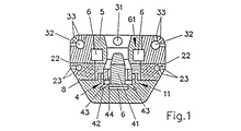
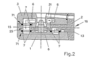
図1および図2にはプラズマ銃ヘッドが横断面図および縦断面図で示されている。ここで更に説明するそのようなプラズマ銃ヘッドの全体的な設計自体は知られているのであるから、ここに示されているプラズマ銃ヘッドの本発明にとって重要である部品および要素についてのみ、以下に詳しく説明することにする。それらの部品および要素はカソード体部材1と、アノード体部材3と、絶縁体部材2およびカソード組立体4ならびにアノードノズル5である。カソード体部材1とアノード体部材3および絶縁体部材2は、相互に平行に延長し、かつプラズマ銃ヘッドの長手中心軸15に平行に延長する連結面に沿って相互に連結される。
【0029】
カソード体部材1とアノード体部材3の間に配置される絶縁体部材2がそれらの部材1と3を相互に絶縁する。
【0030】
絶縁体部材2にはフランジ部材21が設けられる。そのフランジ部材の前端部面16にはこのプラズマ銃ヘッドの動作に必要とする供給管、導体およびパイプの全てが配置される。フランジ部材21はカソード体部材1とアノード体部材3の前端部面を覆う。図2に電気供給導体13を見ることができる。この導体は絶縁体部材2に挿入され、電力をカソード体部材1に供給する。このプラズマ銃ヘッドを動作させるために必要な全ての供給管、パイプ、通路および導電体が絶縁体部材2のフランジ21を貫通する。この目的のためにそのフランジには対応する孔が設けられる。図示を明確にするために図にはそれらの孔は示されていない。
【0031】
カソード体部材1はカソードソケット部材11を備えている。そのカソードソケット部材にはカソード体部材1の内部から接近できる。ソケット部材11は、実際のカソード部材41と円形ガス分配部材42で構成されているカソード組立体4を受けるねじソケットとして設計されている。アノードノズル5が、どのような封じ要素も使用することなしにアノード体部材にきつく挿入される。圧入または好ましくはろう付けによってアノードノズル5の固定を行うことができる。
【0032】
更に、好ましくはセラミック材料で構成する円形絶縁部材8がカソード組立体4を囲んで設けられる。この絶縁部材はカソード組立体を電気的に絶縁するばかりでなく、熱的にも絶縁する。
【0033】
プラズマ銃ヘッドを冷却するために、複数の冷却通路部6で構成される冷却通路が設けられている。冷却通路は前端部において絶縁体部材2に向かって開く。
【0034】
絶縁体部材2の内部では冷却通路部6はアノード体部材に対して90°曲げられる。その後で、冷却通路部はアノードノズル5を通って延長し、そこで円形冷却通路61の形を取る。ここで、冷却通路部6は再び90°曲げられ、絶縁体部材2の孔25を通じてカソード体部材1に開く。絶縁体部材2の内部でその冷却通路部6は更に90°曲げられる。カソード体部材1の内部で、冷却通路部6はカソード組立体4の後ろ側を通って延長し、また再び90°曲げられた後で絶縁体部材2に開く。その絶縁体部材からその冷却通路部は絶縁体部材2の前端部面から導き出される。カソード体部材1と、絶縁体部材2と、アノード体部材3とに設けられる冷却通路部6のそのような直列構成によって、冷却通路の横断面が、従来知られている冷却通路の並列構成における横断面よりも大きくされる。
【0035】
プラズマ銃ヘッドを動作させるために必要なプラズマガスが2つのガス通路43を通じて供給される。それらのガス通路43はカソード体部材1の前端部面に開き、カソード体部材1を横方向に通ってカソードソケット11まで延長する。
【0036】
カソードソケット11から、プラズマガスは、円形ガス分配部材42に設けられている貫通孔44を通って導かれ、発生すべきプラズマトーチの領域に入る。被覆材料の供給は、アノード体部材3の前端部面に設けられている孔31を通じて行われる。アンテナ31はアノード体部材3を通って延長し、アノードノズル部材5に対してほぼ半径方向に開く。
【0037】
アノードノズル部材5はアノード体部材3に圧入またはろう付けされるので、アノードノズル部材5に関してアノードノズル部材5の周囲を環状通路61の形で延長している冷却通路を封ずる必要はない。したがって、通常はOリングの形の、この熱を高く負荷される区域、におけるどのような封じ部材も避けることができる。直列連結されている別々の冷却通路部6を封じるために、カソード体部材1から絶縁体部材2までの遷移領域と、絶縁体部材2からアノード体部材3までの遷移領域とにOリング封じ部材7が設けられる。それらのOリング封じ部材7を受けるために、カソード体部材1と絶縁体部材2にOリング封じ部材7に対応する窪み71が設けられる。
【0038】
更に、絶縁体部材2の前端部面に開き、その絶縁体部材の内部をそれの長手方向側方に沿ってそれの端部領域まで延長する、長手方向に延長する2つの孔22が絶縁体部材2に設けられる。それらの長手方向孔22の延長部に沿って、複数の横孔23が上記長手方向孔22から絶縁体部材2の外側まで、半径方向に延長する。
【0039】
アノード体部材3の前端部面に開き、その絶縁体部材の内部をそれの長手方向側方に沿ってそれの端部領域まで延長する、長手方向に延長する2つの孔32がアノード体部材3に設けられる。また、それらの長手方向孔32の延長部に沿って、複数の横孔33が上記長手方向孔32からアノード体部材3の外側まで、半径方向に延長する。
【0040】
アノード体部材3に設けられて、それの外側まで進む横孔33が3つの群に配置される。プラズマ銃ヘッドの長手方向に見て、それら3つの群のおのおのの横孔33は種々の角度でアノード体部材の外側まで進む。同様に、絶縁体部材2に設けられている横孔23も3つの群に配置される。したがって、この場合には横孔23のただ2つの群が設けられる。
【0041】
上記横孔23、33によって、それぞれ絶縁体部材2とアノード体部材3を更に冷却することができる。他方、上記横孔23、33によって、基板領域、またはプラズマ銃ヘッドを囲む被覆、あるいは両方をそれぞれ冷却できる。被覆作業を不活性ガス中で行う場合には、アルゴンを冷却ガスとして使用することが好ましく、大気中で被覆作業を行う場合には、冷却ガスとして空気を使用できる。
【0042】
図2からわかるように、プラズマ銃ヘッドの頂部と底部は扁円状である。この扁円状設計によって、一方では、横断面が円形で、同じ横断面面積を持つプラズマ銃ヘッドよりも大きい横断面の冷却通路をプラズマ銃ヘッドの内部に設けることができる。他方、この設計によって、アノード体部材と被覆すべき基板との間に一層最適な噴射距離を実現できる。
【0043】
図3はプラズマ銃ヘッドの側面図を示す。この図では、絶縁体部材2に設けられて、それの内部に設けられている縦孔から外側まで進む上記横孔23と、アノード体部材3に設けられて、それの内部に設けられている縦孔から外側まで進む上記横孔33とがはっきり見える。更に、図3は、プラズマ銃ヘッドの動作に必要な何本かの供給管と導体10も示す。作業の設定に応じて、横孔22と33の数、およびそれらの横孔のそれぞれ絶縁体部材2とアノード体部材3からの出口角度を必要な冷却性能に適合させることが可能である。更に、それらの横孔22と33から逃げる冷却ガスまたは冷却空気の単位時間当たりの量を、ある限界内で変更でき、それによって冷却性能を偏向できる。
【0044】
要約すれば、本発明に従って設計されたプラズマ銃ヘッドによって、既知の類似するプラズマ銃ヘッドと比較して、より高い被覆性能を長時間にわたって達成できると述べることができる。それの主な理由は、封じ部材、とくに周囲条件の影響を受けやすいOリング封じ部材7がプラズマ銃ヘッドの内部の、最高の熱負荷を受ける区域から遠い場所に配置されること、および本発明のプラズマ銃ヘッドの冷却性能が、既知のプラズマ銃ヘッドと比較してはるかに改善され、かつ最適にされていることである。したがって、本発明により提供されるプラズマ銃ヘッドを用いると、空所および直径が比較的小さい孔、通路等の壁でも被覆できる。被覆作業によって発生される熱を非常に効率良く逃がすことが、狭い空所や、小さい孔、通路等の場合においてはできず、その結果として既知のプラズマ銃ヘッドが、Oリング封じ部材が破壊されて、それの封じ機能を失う程度まで加熱されるため、これまでこのような被覆は可能でなかった。そのため、既知のプラズマ銃ヘッドは短い作業時間の後で損傷を受け、完全に破壊されてしまうこともある。
【0045】
アノード体部材3全体と一体式のアノードノズル部材5とは、摩耗にさらされる部品として設計できるので、プラズマ粉末パイプ31を別々に交換可能なモジュールとして設計する必要はない。要求があれば、アノード体部材3全体をそっくり交換できる。
【0046】
アノード体部材5は銅合金で構成することが好ましく、またタングステンを使用することも可能である。カソード体部材1とアノード体部材3は黄銅で製作することが好ましい。その理由は、黄銅は、一方では、電気伝導率が高く、他方では機械加工が容易だからである。
【図面の簡単な説明】
【図1】プラズマ銃ヘッドの横断面図である。
【図2】プラズマ銃ヘッドの縦断面図である。
【図3】プラズマ銃ヘッドの外形図である。
【符号の説明】
1 カソード体部材
2 絶縁体部材
3 アノード体部材
4 カソード組立体
5 アノードノズル
6 冷却通路部
7 封じ部材
22,23 孔
23,33 横孔[0001]
[Industrial application fields]
The present invention relates to a plasma gun head used in a plasma injection apparatus, comprising a cathode body member, an anode body member, and an insulator member disposed between the cathode body member and the anode body member. . The cathode body member includes cathode assembly means, the anode body member includes an anode nozzle, and the cathode body member and the anode nozzle extend in a direction perpendicular to the longitudinal central axis of the plasma gun head.
[0002]
The cathode body member and the anode body member are provided with a cooling passage portion adapted to receive a liquid cooling medium, and a circular passage is formed in the area of the anode nozzle means so that the liquid cooling medium flows around the anode nozzle. A sealing member is provided to seal the cooling passage.
[0003]
A plasma gun head of the type described above is preferably used to coat the interior walls of the void, such as tube walls, hole walls, passage walls, and the like. In order to be able to cover the shoulders and bends present in the inner wall of the cavity and to ensure a uniform and uniform thickness of the coating material to be deposited, It has proved advantageous to arrange an electrode composed of a cathode. Thus, the longitudinal central axis of the plasma torch generated by the plasma gun head extends perpendicular to the longitudinal central axis of the plasma gun head. In order to avoid heating the plasma gun head during the coating operation, the plasma gun head must be provided with a cooling device, most often a liquid cooling device.
[0004]
[Prior art]
European Patent Specification No. 0171793 discloses a plasma gun head exhibiting the above structural features. The plasma gun head has a cathode half shell and an anode half shell. The two half shells are separated from each other by an insulating plate. A cathode assembly, termed an electrode, is inserted into the cathode half shell and a burner nozzle is inserted into the anode half shell. It is said that the electrode and burner nozzle can be easily replaced. In order to cool the burner nozzle, a cooling passage incorporating an annular passage portion surrounding the burner nozzle is provided. Sealing of the annular passage with respect to the burner nozzle inserted is effected by two O-ring sealing members. In order to cool the two O-ring sealing members, additional cooling passages leading to the O-ring sealing members are provided. In order to cool the cathode half shell in which the cathode assembly is inserted, another cooling passage is provided in the form of an annular passage in the force of the cathode assembly. However, the annular passage is not led directly to the cathode assembly.
[0005]
The covering operation can be performed by such a burner nozzle. In this coating operation, the heat generated by the burner nozzle during the coating operation is quickly and efficiently removed. To ensure efficient heat removal, it is important that air can freely circulate around the burner nozzle. More importantly, the induced heat is removed from the substrate in order to avoid further heating of the burner nozzle by the thermal radiation generated by the substrate to be coated.
[0006]
However, if the inner wall of the pipe or passage having a relatively small inner diameter is to be coated, the heat generated by the coating operation is gradually and inefficiently removed, resulting in extremely strong heating of the burner nozzle. Such heating of the burner nozzle may occur to the extent that the burner nozzle is damaged. Very often the burner nozzle damage is such that the burner nozzle is completely destroyed. Through thorough analysis of such cases, it has been found that the reason for the destruction or damage of the burner nozzle is to be found in the O-ring seal. This is because they cannot withstand high heat loads for a long time.
[0007]
The reason can probably be considered that the O-ring sealing member is fitted tightly and directly contacts the burner nozzle. Even if one side of the O-ring seal is cooled by the cooling medium, the O-ring seal begins to melt or a positive seal of the circular cooling passage that surrounds the burner nozzle under the action of the hot burner nozzle There is a risk that the properties and characteristics of the O-ring sealing member will change to the extent that can no longer be secured. However, even if the coolant leaks to the burner nozzle area to the minimum, the plasma gun head will be severely damaged or destroyed.
[0008]
The risk of damage to the O-ring sealing member and the resulting damage to the plasma gun head increases as the operation time of the plasma gun head increases, in particular, the inner walls of small diameter tubes, passages, etc. are covered. That is the case. This is because in that case the efficiency with which heat is removed is low.
[0009]
Thus, plasma gun heads known in the art are suitable to operate for a strictly limited time when the inner walls of small diameter tubes, passages, etc. must be coated.
[0010]
Another disadvantage of the plasma gun head known in the art is that it can only be used for reasonable coating performance. As the coating performance, i.e. the deposition of coating material per unit time, increases, the known plasma gun head heats up more quickly, with the result that the O-ring sealing member is already destroyed after a very short working time. It will be. However, in order to be able to perform the coating operation more efficiently at a lower cost, it is desirable on the one hand to increase the uninterrupted working time of the plasma gun head and on the other hand to increase the coating performance.
[0011]
In order to achieve as uniform a quality coating as possible, it is often required that the coating operation should not be interrupted if a series of workpieces must be coated in the same manner. This may cause the plasma gun head to operate continuously for days. In order to be able to withstand such a severe operation, it is necessary to optimize and improve the cooling of the probe. With known plasma gun heads, the coating operation cannot be continued for such a long period of time, especially when the inner walls of small diameter tubes, passages, etc. have to be coated.
[0012]
[Problems to be solved by the invention]
It is an object of the present invention to obtain a plasma gun head that is particularly suitable for coating the inner walls of small diameter tubes, passages, etc., with improved cooling and therefore can be operated for a long time.
[0013]
Another object of the present invention is to obtain a plasma gun head that is particularly suitable for coating inner walls of small diameter tubes, passages, etc., allowing higher coating performance (material deposition per unit time) to be achieved. .
[0014]
Yet another object of the present invention is to provide a plasma gun head that is particularly suitable for coating inner walls of small diameter tubes, passages, etc. that have very small physical dimensions and can still operate for long periods of time with high coating performance. .
[0015]
[Means for Solving the Problems]
In order to achieve these and other objects, the present invention is arranged between a cathode body member, an anode body member, and a cathode body member and the anode body member so that the cathode body member and the anode body member are mutually connected. And an insulating member that electrically insulates, to obtain a plasma gun head for use in a plasma injection apparatus.
[0016]
The cathode body member includes a cathode assembly, and the anode body member includes an anode nozzle. The cathode assembly and anode nozzle extend perpendicular to the central longitudinal axis of the plasma gun head.
[0017]
The cathode body member and the anode body member have a cooling passage portion adapted to receive a liquid cooling medium. The cooling passage portion forms a circular passage in the region of the anode nozzle so that the liquid cooling medium flows around the anode nozzle means.
[0018]
A sealing element seals the cooling passage. The sealing elements are provided on the cathode body member and the anode body member, respectively, of the transition region of the cooling passage portion between the cathode body member and the insulator member and the transition region of the cooling passage portion between the insulator member and the anode body member. It is arranged at a certain distance.
[0019]
The cooling passage portion in the anode body member and the cooling passage portion in the cathode body member are connected in series with respect to the flow direction of the liquid cooling medium. The anode nozzle of the plasma gun head of the present invention is firmly connected to the anode body member without the use of a sealing element.
[0020]
Such a plasma gun head first makes it possible to eliminate the need for any sealing means in the area of the anode nozzle of the plasma gun head to seal the cooling passage that reaches the anode nozzle. Therefore, it has been provided in this area so far, especially in the case of small plasma gun heads, which are subject to very high wear in the case of high covering performance and long time operation of the plasma gun head. The sealing element can be avoided completely. The cooling elements necessary to seal the cooling passages can be placed in areas of the plasma gun head that are not subject to high thermal stresses.
[0021]
Since the cooling passages are connected in series as viewed in the flow direction of the cooling medium, it is possible to provide a cooling passage that occupies a high proportion of the cross-sectional area in the total available cross-sectional area of the plasma gun head. . Thereby, the cooling efficiency is significantly improved.
[0022]
According to a preferred embodiment of the plasma gun head of the present invention, the cathode assembly is inserted into the cathode socket member provided on the cathode body member so that it can be extracted from the inside of the cathode body member. A cooling passage extending through the cathode body member extends through the rear side of the cathode assembly. Thus, it is possible that the cooling passage portion in the region of the cathode body member should not be designed as a circular passage portion. Therefore, the cooling passage portion can have a larger cross-sectional area, resulting in a lower flow resistance value and higher cooling efficiency. Furthermore, such a design makes it possible to avoid providing a sealing element in the area of the cathode body member, in contrast to most known plasma gun heads.
[0023]
In summary, such plasma gun heads are much more efficient to cool than comparable conventional plasma gun heads. Therefore, it is appropriate to use it under harsh conditions even under unfavorable thermal conditions.
[0024]
According to another preferred embodiment of the present invention, the insulator member is provided with a vertical hole extending along both side surfaces of the insulator member and a plurality of lateral holes leading to the outside of the insulator member. These holes function to supply a gaseous medium, for example air. To that end, the plasma gun head itself is further cooled and can be further used to cool the deposited coating, the substrate to be coated, or both.
[0025]
According to another preferred embodiment of the present invention, the anode body member is provided with a vertical hole extending along both side surfaces of the anode body member and a plurality of lateral holes leading to the outside of the insulator member. These holes function to supply a gaseous medium, for example air. To that end, the plasma gun head itself is further cooled and can be further used to cool the deposited coating, the substrate to be coated, or both.
[0026]
The cross section of the plasma gun head of the present invention can be substantially trapezoidal. By doing so, a cooling passage with a larger cross-section than a plasma gun head having a circular cross-section with the same cross-sectional area can be provided inside the plasma gun head. On the other hand, this design allows a more optimal distance between the anode body member and the substrate to be coated.
[0027]
【Example】
Hereinafter, embodiments of the plasma gun head of the present invention will be further described with reference to the accompanying drawings.
[0028]
1 and 2 show the plasma gun head in a cross-sectional view and a longitudinal cross-sectional view. Since the overall design of such a plasma gun head as further described herein is known per se, only the parts and elements of the plasma gun head shown here that are important to the present invention will be described below. I will explain in detail. These parts and elements are a cathode body member 1, an
[0029]
An
[0030]
The
[0031]
The cathode body member 1 includes a
[0032]
In addition, a circular insulating member 8, preferably made of a ceramic material, is provided surrounding the cathode assembly 4. This insulating member not only electrically insulates the cathode assembly, but also insulates it thermally.
[0033]
In order to cool the plasma gun head, a cooling passage composed of a plurality of cooling
[0034]
Inside the
[0035]
Plasma gas necessary for operating the plasma gun head is supplied through the two
[0036]
From the
[0037]
Since the
[0038]
In addition, two longitudinally extending
[0039]
Two longitudinally extending
[0040]
The lateral holes 33 provided in the
[0041]
The
[0042]
As can be seen from FIG. 2, the top and bottom of the plasma gun head are oblong. With this oblong design, on the one hand, a cooling passage with a larger cross-section than a plasma gun head having a circular cross-section and the same cross-sectional area can be provided inside the plasma gun head. On the other hand, this design makes it possible to achieve a more optimal injection distance between the anode body member and the substrate to be coated.
[0043]
FIG. 3 shows a side view of the plasma gun head. In this figure, it is provided in the
[0044]
In summary, it can be stated that a plasma gun head designed in accordance with the present invention can achieve higher coating performance over a longer period of time compared to known similar plasma gun heads. The main reason for this is that the sealing member, in particular the O-
[0045]
The entire
[0046]
The
[Brief description of the drawings]
FIG. 1 is a cross-sectional view of a plasma gun head.
FIG. 2 is a longitudinal sectional view of a plasma gun head.
FIG. 3 is an external view of a plasma gun head.
[Explanation of symbols]
DESCRIPTION OF SYMBOLS 1
Claims (14)
Applications Claiming Priority (2)
| Application Number | Priority Date | Filing Date | Title |
|---|---|---|---|
| DE4333068.1 | 1993-09-29 | ||
| DE4333068 | 1993-09-29 |
Publications (2)
| Publication Number | Publication Date |
|---|---|
| JPH07169406A JPH07169406A (en) | 1995-07-04 |
| JP3640985B2 true JP3640985B2 (en) | 2005-04-20 |
Family
ID=6498894
Family Applications (1)
| Application Number | Title | Priority Date | Filing Date |
|---|---|---|---|
| JP23550394A Expired - Lifetime JP3640985B2 (en) | 1993-09-29 | 1994-09-29 | Plasma gun head used in plasma injection equipment |
Country Status (7)
| Country | Link |
|---|---|
| US (1) | US5519183A (en) |
| EP (1) | EP0645946B1 (en) |
| JP (1) | JP3640985B2 (en) |
| KR (1) | KR100303959B1 (en) |
| AT (1) | ATE146643T1 (en) |
| CA (1) | CA2132178C (en) |
| DE (1) | DE59401323D1 (en) |
Families Citing this family (24)
| Publication number | Priority date | Publication date | Assignee | Title |
|---|---|---|---|---|
| TW315340B (en) * | 1995-02-13 | 1997-09-11 | Komatsu Mfg Co Ltd | |
| DE50005068D1 (en) | 1999-06-30 | 2004-02-26 | Sulzer Metco Ag Wohlen | Plasma spray device |
| CA2356583C (en) * | 2001-03-28 | 2007-10-16 | Nippon Welding Rod Co., Ltd. | Torch for powder plasma buildup welding |
| US6478234B1 (en) | 2001-06-18 | 2002-11-12 | Northrop Grumman Corporation | Adjustable injector assembly for melted powder coating deposition |
| ATE360975T1 (en) * | 2003-12-09 | 2007-05-15 | Amt Ag | PLASMA SPRAY DEVICE |
| FR2884742B1 (en) * | 2005-04-26 | 2008-10-10 | Snecma Moteurs Sa | PLASMA WELDING TORCH |
| SE529053C2 (en) | 2005-07-08 | 2007-04-17 | Plasma Surgical Invest Ltd | Plasma generating device, plasma surgical device and use of a plasma surgical device |
| SE529058C2 (en) * | 2005-07-08 | 2007-04-17 | Plasma Surgical Invest Ltd | Plasma generating device, plasma surgical device, use of a plasma surgical device and method for forming a plasma |
| SE529056C2 (en) | 2005-07-08 | 2007-04-17 | Plasma Surgical Invest Ltd | Plasma generating device, plasma surgical device and use of a plasma surgical device |
| US7928338B2 (en) * | 2007-02-02 | 2011-04-19 | Plasma Surgical Investments Ltd. | Plasma spraying device and method |
| US7589473B2 (en) * | 2007-08-06 | 2009-09-15 | Plasma Surgical Investments, Ltd. | Pulsed plasma device and method for generating pulsed plasma |
| US8735766B2 (en) * | 2007-08-06 | 2014-05-27 | Plasma Surgical Investments Limited | Cathode assembly and method for pulsed plasma generation |
| US9192040B2 (en) | 2010-01-26 | 2015-11-17 | Leibniz-Institut Fuer Plasmaforschung Und Technologie E.V., Inp Greifswald | Device and method for generating an electrical discharge in hollow bodies |
| WO2011091842A1 (en) | 2010-01-26 | 2011-08-04 | Leibniz-Institut Für Plasmaforschung Und Technologie E. V. | Device and method for dry-cleaning, activating, coating, modifying, and biologically decontaminating the inner walls of hoses, pipes, and other hollow bodies |
| US8941025B2 (en) * | 2010-01-26 | 2015-01-27 | Oerlikon Metco (Us) Inc. | Plume shroud for laminar plasma guns |
| US8613742B2 (en) * | 2010-01-29 | 2013-12-24 | Plasma Surgical Investments Limited | Methods of sealing vessels using plasma |
| US9089319B2 (en) | 2010-07-22 | 2015-07-28 | Plasma Surgical Investments Limited | Volumetrically oscillating plasma flows |
| EP2806977B1 (en) * | 2012-01-27 | 2020-03-18 | Oerlikon Metco (US) Inc. | Thermo spray gun with removable nozzle tip and method making and using the same |
| US9704694B2 (en) | 2014-07-11 | 2017-07-11 | Rolls-Royce Corporation | Gas cooled plasma spraying device |
| CN104684234B (en) * | 2014-12-24 | 2017-02-22 | 徐州科融环境资源股份有限公司 | High-power air-cooled plasma generator |
| CN106304594A (en) * | 2016-09-29 | 2017-01-04 | 成都真火科技有限公司 | A kind of laminar flow plasma generator |
| CN109536874B (en) * | 2019-01-22 | 2024-01-09 | 中国人民解放军陆军装甲兵学院 | Inner hole plasma spraying device with deflection angle spraying function |
| IL300972A (en) | 2020-08-28 | 2023-04-01 | Plasma Surgical Invest Ltd | Systems, methods, and devices for generating predominantly radially expanded plasma flow |
| DE102023200269A1 (en) | 2023-01-13 | 2024-07-18 | Volkswagen Aktiengesellschaft | Nozzle plate for a plasma spraying machine for atmospheric plasma spraying and plasma spraying machine |
Family Cites Families (8)
| Publication number | Priority date | Publication date | Assignee | Title |
|---|---|---|---|---|
| FR1338390A (en) * | 1962-07-05 | 1963-09-27 | Air Liquide | Adjustable plasma generator head |
| US3851140A (en) * | 1973-03-01 | 1974-11-26 | Kearns Tribune Corp | Plasma spray gun and method for applying coatings on a substrate |
| US4121082A (en) * | 1977-04-27 | 1978-10-17 | Metco, Inc. | Method and apparatus for shielding the effluent from plasma spray gun assemblies |
| US4423304A (en) * | 1981-02-20 | 1983-12-27 | Bass Harold E | Plasma welding torch |
| DE3430383A1 (en) * | 1984-08-17 | 1986-02-27 | Plasmainvent AG, Zug | PLASMA SPRAY BURNER FOR INTERNAL COATINGS |
| DE3642375A1 (en) * | 1986-12-11 | 1988-06-23 | Castolin Sa | METHOD FOR APPLYING AN INTERNAL COATING INTO TUBES OD. DGL. CAVITY NARROW CROSS SECTION AND PLASMA SPLASH BURNER DAFUER |
| US4843208A (en) * | 1987-12-23 | 1989-06-27 | Epri | Plasma torch |
| DE69325802T2 (en) * | 1992-05-13 | 2000-04-27 | Sulzer Metco Ag, Wohlen | HIGH TEMPERATURE PLASMA SPRAY GUN |
-
1994
- 1994-09-05 AT AT94810508T patent/ATE146643T1/en not_active IP Right Cessation
- 1994-09-05 DE DE59401323T patent/DE59401323D1/en not_active Expired - Lifetime
- 1994-09-05 EP EP94810508A patent/EP0645946B1/en not_active Expired - Lifetime
- 1994-09-12 US US08/304,132 patent/US5519183A/en not_active Expired - Lifetime
- 1994-09-15 CA CA002132178A patent/CA2132178C/en not_active Expired - Lifetime
- 1994-09-28 KR KR1019940024491A patent/KR100303959B1/en not_active IP Right Cessation
- 1994-09-29 JP JP23550394A patent/JP3640985B2/en not_active Expired - Lifetime
Also Published As
| Publication number | Publication date |
|---|---|
| DE59401323D1 (en) | 1997-01-30 |
| KR950010715A (en) | 1995-04-28 |
| KR100303959B1 (en) | 2001-12-01 |
| CA2132178A1 (en) | 1995-03-30 |
| JPH07169406A (en) | 1995-07-04 |
| CA2132178C (en) | 1999-01-12 |
| US5519183A (en) | 1996-05-21 |
| EP0645946B1 (en) | 1996-12-18 |
| ATE146643T1 (en) | 1997-01-15 |
| EP0645946A1 (en) | 1995-03-29 |
Similar Documents
| Publication | Publication Date | Title |
|---|---|---|
| JP3640985B2 (en) | Plasma gun head used in plasma injection equipment | |
| CA2104543C (en) | Plasma gun assembly | |
| CN101167412B (en) | Interchangeable plasma nozzle interface | |
| CN102239021B (en) | Device for ejecting droplets of a fluid having a high temperature | |
| US4877937A (en) | Plasma spray torch | |
| EP0106091B1 (en) | Plasma spray gun | |
| KR100646915B1 (en) | Nozzle for Plasma Torch | |
| US20150144603A1 (en) | High Access Consumables for a Plasma Arc Cutting System | |
| EP0640022B1 (en) | High temperature plasma gun assembly | |
| JPS61135484A (en) | Wire feeder | |
| KR20020013849A (en) | Plasma torch cartridge and plasma torch equipped therewith | |
| US4393298A (en) | Liquid cooling for a welding torch | |
| JP6073475B2 (en) | Tungsten inert gas welding | |
| US6386140B1 (en) | Plasma spraying apparatus | |
| US7375301B1 (en) | Modular anode support member for plasma spray gun | |
| JPS5853381A (en) | Water cooling type gas shield welding burner for automatic welding apparatus having gas nozzle blowing out gas from interior | |
| US6897402B2 (en) | Plasma-arc spray anode and gun body | |
| JPH03500107A (en) | Arc furnace electrode support arm | |
| US6377604B1 (en) | Current-conducting arm for an electric arc furnace | |
| JP3305185B2 (en) | Plasma spraying equipment | |
| JP3324169B2 (en) | Constrictor type arc heater | |
| US11700682B2 (en) | Thermoelectric cooling of consumables in a plasma torch | |
| RU2145536C1 (en) | Plasmatron for air-plasma cutting | |
| WO2001078939A1 (en) | A nozzle holder for a liquid cooled electric welding gun | |
| US3480717A (en) | Arc furnace electrode assembly |
Legal Events
| Date | Code | Title | Description |
|---|---|---|---|
| TRDD | Decision of grant or rejection written | ||
| A01 | Written decision to grant a patent or to grant a registration (utility model) |
Free format text: JAPANESE INTERMEDIATE CODE: A01 Effective date: 20050111 |
|
| A61 | First payment of annual fees (during grant procedure) |
Free format text: JAPANESE INTERMEDIATE CODE: A61 Effective date: 20050120 |
|
| R150 | Certificate of patent or registration of utility model |
Free format text: JAPANESE INTERMEDIATE CODE: R150 |
|
| FPAY | Renewal fee payment (event date is renewal date of database) |
Free format text: PAYMENT UNTIL: 20080128 Year of fee payment: 3 |
|
| FPAY | Renewal fee payment (event date is renewal date of database) |
Free format text: PAYMENT UNTIL: 20090128 Year of fee payment: 4 |
|
| FPAY | Renewal fee payment (event date is renewal date of database) |
Free format text: PAYMENT UNTIL: 20090128 Year of fee payment: 4 |
|
| FPAY | Renewal fee payment (event date is renewal date of database) |
Free format text: PAYMENT UNTIL: 20100128 Year of fee payment: 5 |
|
| FPAY | Renewal fee payment (event date is renewal date of database) |
Free format text: PAYMENT UNTIL: 20110128 Year of fee payment: 6 |
|
| FPAY | Renewal fee payment (event date is renewal date of database) |
Free format text: PAYMENT UNTIL: 20110128 Year of fee payment: 6 |
|
| FPAY | Renewal fee payment (event date is renewal date of database) |
Free format text: PAYMENT UNTIL: 20120128 Year of fee payment: 7 |
|
| FPAY | Renewal fee payment (event date is renewal date of database) |
Free format text: PAYMENT UNTIL: 20120128 Year of fee payment: 7 |
|
| FPAY | Renewal fee payment (event date is renewal date of database) |
Free format text: PAYMENT UNTIL: 20130128 Year of fee payment: 8 |
|
| FPAY | Renewal fee payment (event date is renewal date of database) |
Free format text: PAYMENT UNTIL: 20140128 Year of fee payment: 9 |
|
| R250 | Receipt of annual fees |
Free format text: JAPANESE INTERMEDIATE CODE: R250 |
|
| EXPY | Cancellation because of completion of term |