JP3638601B2 - Method and apparatus for casting hollow fiber membranes - Google Patents
Method and apparatus for casting hollow fiber membranes Download PDFInfo
- Publication number
- JP3638601B2 JP3638601B2 JP51349994A JP51349994A JP3638601B2 JP 3638601 B2 JP3638601 B2 JP 3638601B2 JP 51349994 A JP51349994 A JP 51349994A JP 51349994 A JP51349994 A JP 51349994A JP 3638601 B2 JP3638601 B2 JP 3638601B2
- Authority
- JP
- Japan
- Prior art keywords
- block
- nozzle
- computer
- hollow fiber
- pattern
- Prior art date
- Legal status (The legal status is an assumption and is not a legal conclusion. Google has not performed a legal analysis and makes no representation as to the accuracy of the status listed.)
- Expired - Fee Related
Links
Images


Classifications
-
- D—TEXTILES; PAPER
- D01—NATURAL OR MAN-MADE THREADS OR FIBRES; SPINNING
- D01D—MECHANICAL METHODS OR APPARATUS IN THE MANUFACTURE OF ARTIFICIAL FILAMENTS, THREADS, FIBRES, BRISTLES OR RIBBONS
- D01D5/00—Formation of filaments, threads, or the like
- D01D5/24—Formation of filaments, threads, or the like with a hollow structure; Spinnerette packs therefor
-
- B—PERFORMING OPERATIONS; TRANSPORTING
- B01—PHYSICAL OR CHEMICAL PROCESSES OR APPARATUS IN GENERAL
- B01D—SEPARATION
- B01D69/00—Semi-permeable membranes for separation processes or apparatus characterised by their form, structure or properties; Manufacturing processes specially adapted therefor
- B01D69/08—Hollow fibre membranes
-
- B—PERFORMING OPERATIONS; TRANSPORTING
- B29—WORKING OF PLASTICS; WORKING OF SUBSTANCES IN A PLASTIC STATE IN GENERAL
- B29C—SHAPING OR JOINING OF PLASTICS; SHAPING OF MATERIAL IN A PLASTIC STATE, NOT OTHERWISE PROVIDED FOR; AFTER-TREATMENT OF THE SHAPED PRODUCTS, e.g. REPAIRING
- B29C48/00—Extrusion moulding, i.e. expressing the moulding material through a die or nozzle which imparts the desired form; Apparatus therefor
- B29C48/03—Extrusion moulding, i.e. expressing the moulding material through a die or nozzle which imparts the desired form; Apparatus therefor characterised by the shape of the extruded material at extrusion
- B29C48/05—Filamentary, e.g. strands
-
- B—PERFORMING OPERATIONS; TRANSPORTING
- B29—WORKING OF PLASTICS; WORKING OF SUBSTANCES IN A PLASTIC STATE IN GENERAL
- B29C—SHAPING OR JOINING OF PLASTICS; SHAPING OF MATERIAL IN A PLASTIC STATE, NOT OTHERWISE PROVIDED FOR; AFTER-TREATMENT OF THE SHAPED PRODUCTS, e.g. REPAIRING
- B29C48/00—Extrusion moulding, i.e. expressing the moulding material through a die or nozzle which imparts the desired form; Apparatus therefor
- B29C48/03—Extrusion moulding, i.e. expressing the moulding material through a die or nozzle which imparts the desired form; Apparatus therefor characterised by the shape of the extruded material at extrusion
- B29C48/131—Curved articles
-
- B—PERFORMING OPERATIONS; TRANSPORTING
- B29—WORKING OF PLASTICS; WORKING OF SUBSTANCES IN A PLASTIC STATE IN GENERAL
- B29C—SHAPING OR JOINING OF PLASTICS; SHAPING OF MATERIAL IN A PLASTIC STATE, NOT OTHERWISE PROVIDED FOR; AFTER-TREATMENT OF THE SHAPED PRODUCTS, e.g. REPAIRING
- B29C48/00—Extrusion moulding, i.e. expressing the moulding material through a die or nozzle which imparts the desired form; Apparatus therefor
- B29C48/25—Component parts, details or accessories; Auxiliary operations
- B29C48/92—Measuring, controlling or regulating
-
- B—PERFORMING OPERATIONS; TRANSPORTING
- B29—WORKING OF PLASTICS; WORKING OF SUBSTANCES IN A PLASTIC STATE IN GENERAL
- B29C—SHAPING OR JOINING OF PLASTICS; SHAPING OF MATERIAL IN A PLASTIC STATE, NOT OTHERWISE PROVIDED FOR; AFTER-TREATMENT OF THE SHAPED PRODUCTS, e.g. REPAIRING
- B29C2948/00—Indexing scheme relating to extrusion moulding
- B29C2948/92—Measuring, controlling or regulating
- B29C2948/92504—Controlled parameter
- B29C2948/92571—Position, e.g. linear or angular
-
- B—PERFORMING OPERATIONS; TRANSPORTING
- B29—WORKING OF PLASTICS; WORKING OF SUBSTANCES IN A PLASTIC STATE IN GENERAL
- B29C—SHAPING OR JOINING OF PLASTICS; SHAPING OF MATERIAL IN A PLASTIC STATE, NOT OTHERWISE PROVIDED FOR; AFTER-TREATMENT OF THE SHAPED PRODUCTS, e.g. REPAIRING
- B29C2948/00—Indexing scheme relating to extrusion moulding
- B29C2948/92—Measuring, controlling or regulating
- B29C2948/92504—Controlled parameter
- B29C2948/9258—Velocity
- B29C2948/9259—Angular velocity
-
- B—PERFORMING OPERATIONS; TRANSPORTING
- B29—WORKING OF PLASTICS; WORKING OF SUBSTANCES IN A PLASTIC STATE IN GENERAL
- B29C—SHAPING OR JOINING OF PLASTICS; SHAPING OF MATERIAL IN A PLASTIC STATE, NOT OTHERWISE PROVIDED FOR; AFTER-TREATMENT OF THE SHAPED PRODUCTS, e.g. REPAIRING
- B29C2948/00—Indexing scheme relating to extrusion moulding
- B29C2948/92—Measuring, controlling or regulating
- B29C2948/92504—Controlled parameter
- B29C2948/92609—Dimensions
- B29C2948/92666—Distortion, shrinkage, dilatation, swell or warpage
-
- B—PERFORMING OPERATIONS; TRANSPORTING
- B29—WORKING OF PLASTICS; WORKING OF SUBSTANCES IN A PLASTIC STATE IN GENERAL
- B29C—SHAPING OR JOINING OF PLASTICS; SHAPING OF MATERIAL IN A PLASTIC STATE, NOT OTHERWISE PROVIDED FOR; AFTER-TREATMENT OF THE SHAPED PRODUCTS, e.g. REPAIRING
- B29C2948/00—Indexing scheme relating to extrusion moulding
- B29C2948/92—Measuring, controlling or regulating
- B29C2948/92819—Location or phase of control
- B29C2948/92857—Extrusion unit
- B29C2948/92904—Die; Nozzle zone
-
- B—PERFORMING OPERATIONS; TRANSPORTING
- B29—WORKING OF PLASTICS; WORKING OF SUBSTANCES IN A PLASTIC STATE IN GENERAL
- B29C—SHAPING OR JOINING OF PLASTICS; SHAPING OF MATERIAL IN A PLASTIC STATE, NOT OTHERWISE PROVIDED FOR; AFTER-TREATMENT OF THE SHAPED PRODUCTS, e.g. REPAIRING
- B29C2948/00—Indexing scheme relating to extrusion moulding
- B29C2948/92—Measuring, controlling or regulating
- B29C2948/92819—Location or phase of control
- B29C2948/92952—Drive section, e.g. gearbox, motor or drive fluids
-
- B—PERFORMING OPERATIONS; TRANSPORTING
- B29—WORKING OF PLASTICS; WORKING OF SUBSTANCES IN A PLASTIC STATE IN GENERAL
- B29C—SHAPING OR JOINING OF PLASTICS; SHAPING OF MATERIAL IN A PLASTIC STATE, NOT OTHERWISE PROVIDED FOR; AFTER-TREATMENT OF THE SHAPED PRODUCTS, e.g. REPAIRING
- B29C48/00—Extrusion moulding, i.e. expressing the moulding material through a die or nozzle which imparts the desired form; Apparatus therefor
- B29C48/03—Extrusion moulding, i.e. expressing the moulding material through a die or nozzle which imparts the desired form; Apparatus therefor characterised by the shape of the extruded material at extrusion
- B29C48/09—Articles with cross-sections having partially or fully enclosed cavities, e.g. pipes or channels
- B29C48/10—Articles with cross-sections having partially or fully enclosed cavities, e.g. pipes or channels flexible, e.g. blown foils
-
- B—PERFORMING OPERATIONS; TRANSPORTING
- B29—WORKING OF PLASTICS; WORKING OF SUBSTANCES IN A PLASTIC STATE IN GENERAL
- B29K—INDEXING SCHEME ASSOCIATED WITH SUBCLASSES B29B, B29C OR B29D, RELATING TO MOULDING MATERIALS OR TO MATERIALS FOR MOULDS, REINFORCEMENTS, FILLERS OR PREFORMED PARTS, e.g. INSERTS
- B29K2105/00—Condition, form or state of moulded material or of the material to be shaped
- B29K2105/25—Solid
- B29K2105/253—Preform
- B29K2105/258—Tubular
-
- B—PERFORMING OPERATIONS; TRANSPORTING
- B29—WORKING OF PLASTICS; WORKING OF SUBSTANCES IN A PLASTIC STATE IN GENERAL
- B29L—INDEXING SCHEME ASSOCIATED WITH SUBCLASS B29C, RELATING TO PARTICULAR ARTICLES
- B29L2031/00—Other particular articles
- B29L2031/753—Medical equipment; Accessories therefor
-
- B—PERFORMING OPERATIONS; TRANSPORTING
- B29—WORKING OF PLASTICS; WORKING OF SUBSTANCES IN A PLASTIC STATE IN GENERAL
- B29L—INDEXING SCHEME ASSOCIATED WITH SUBCLASS B29C, RELATING TO PARTICULAR ARTICLES
- B29L2031/00—Other particular articles
- B29L2031/755—Membranes, diaphragms
-
- B—PERFORMING OPERATIONS; TRANSPORTING
- B29—WORKING OF PLASTICS; WORKING OF SUBSTANCES IN A PLASTIC STATE IN GENERAL
- B29L—INDEXING SCHEME ASSOCIATED WITH SUBCLASS B29C, RELATING TO PARTICULAR ARTICLES
- B29L2031/00—Other particular articles
- B29L2031/756—Microarticles, nanoarticles
Description
これは、1992年2月4日に提出された同時に係属するU.S.S.N.07/831,142(Milliken及びBarnes)の一部継続出願である。
発明の分野
本発明は、全体としては管状中空繊維膜を製造するための方法及び装置に関し、そして更に詳細には中空繊維膜を自動的に注型するためのコンピュータ制御された機械に関する。
発明の背景
本発明は、管状中空繊維膜、例えば、例0.125ミリメートル(mm)の壁厚さを有する6mm径の管状の形を有する膜の種々の形状を注型する製造方法を取り扱う。このような膜は、1991年5月26日に発行された米国特許第5,002,661号中でChickらによって述べられたように、人工膵臓において使用することができる。しかしながら、これらの膜は、非常に破損しやすくそして成形するのが困難である。このような壁−対−径の比を有するつんだ(tight)コイル及び螺旋の形を成形することは特に困難である。
既知の注型方法は、同時押出ダイのノズルの環状オリフィスからポリマー状流体を無理に押出し一方このノズルのセンターコア(心型)から凝固流体を無理に押出すことを含む。相逆転プロセスがこれらの2つの流体の間の接触の点で起きる。結果として、ポリマー状流体が凝固しそして管状構造体を生成させる。管状構造体の凝固速度は凝固流体中の溶媒によって和らげられ、これが、最後の硬化が起きる前の繊維の幾らかの操作を可能にする。押出ダイの数ミリメートル下に、水の大きな浴が存在する。生成する管状構造体をこの浴の中に浸けると、そこで一層の凝固が始まり、そしてそれが完全に凝固されたようになるであろう前に所望の形状に成形される。
ある種の用途においては、特定の形又は形状の、例えば螺旋の又はコイルの形の中空繊維膜を使用することが望ましい。しかしながら、ゆがみ又はけん縮が膜の壁において起きないことが重要である。
発明の要約
従って、本発明の目的は、中空繊維膜を種々の規定された形、例えば螺旋、線状、円形、長方形などに注型するための自動化されたシステムを提供することである。加えて、このシステムは、効率的でありそして高いレベルの再現性を提供しなければならない。システムの生産性を増すであろう、注型の間に(飛行中に(on the fly))形状を変える能力を有することもまた有利であろう。
これらのゴールを達成するために、静止凝固浴の上方でノズルを動かすことが決定された。好ましい実施態様においては、所望の形を有する膜を作るために、静止凝固浴に平行な面の中のノズルの動きを制御するためにコンピュータを使用する。注型は、壁厚さにおいて起きるゆがみを補償するであろうやり方で常にノズルを方向付けなければならないということによって複雑化される。このようなゆがみは、膜が注型されている時の膜の曲がりによって起きる。押出物の流れパターンを調節してカーブの内側によりも外側により多くのポリマーを供給しない限り、構造体の外の繊維は延ばされそして内の繊維は圧縮され、これが内の壁よりも薄い外の壁をもたらす。これを補償するためには、ノズルの環は、環の一部を流体がノズルを出る点で反対の部分よりも少し厚くするためにオフセットである。本発明によれば、ノズルの方向付けを、より多くのポリマーが内の縁に沿ってよりも膜のカーブになった区分の外の縁に沿って供給されるように制御する。これは、均一に対称的な壁厚さを結果としてもたらす。好ましい実施態様においては、“シイタア”(θ)と呼ばれる回転の第三軸が制御プログラム中に含まれる(“シイタア”及び“θ”は、本明細書及び添付の図面中で交換可能に使用される)。ノズルが例えば90゜の角度を通して半径に沿って動かされる時に、ノズルは同じ方向に90゜だけ回転されるが、この回転は巻き(turn)が作られるにつれて整合される。
従って、本発明によって取り囲まれる方法は、(a)同時押出ダイのノズルの環状オリフィスからポリマー状流体を無理に押出し一方該ノズルのセンターコア(心型)から凝固流体を無理に押出すこと、及び(b)凝固浴の表面の上方のそしてそれに平行な面の中での該ノズルの動きを、規定された形の中空繊維膜を前記の浴の中で生成させるように前記の動きを制御しながら、自動的に遂行することのステップを含んで成る。好ましい実施態様においては、ステップ(b)は、実質的に均一な壁厚さの中空繊維膜を注型するために、少なくとも3つの軸、X、Y及びθに対する前記のノズルの整合された動きを遂行することを含んで成る。本発明によれば、ポリマー状流体は、ノズル内でオフセットである環状オリフィスを通して押出され、そしてノズルは、X及びY軸に沿った動きと整合させてθ軸の回りに回転させることができる。ノズルの動きは、有利には環状オリフィスのオフセット及びポリマー状流体の粘度に従って遂行することができる。一つの好ましい実施態様においては、本発明の方法を、約4〜7ミリメートルの内径及び約100〜200マイクロメートルの壁厚さを有する中空繊維膜を注型するために適応させる。勿論、本発明はまた、他の領域の径及び壁厚さを達成することができる。
本発明による装置は、オフセットの環状オリフィス及びセンターコア(心型)を持つノズルを有する同時押出ダイ、前記の環状オリフィスからポリマー状流体を無理に押出し一方前記のセンターコア(心型)から凝固流体を無理に押出すための手段、並びに規定された形の中空繊維膜を凝固浴の中で生成させるように前記のノズルの動きを制御しながら、前記の浴の表面の上方のそしてそれに平行な面の中で前記のノズルを自動的に動かすための手段を含む、上述のステップを実施するための手段を含む。
加えて、本発明は、中空繊維膜を自動的に注型するためのシステムの制御のためのコード化された命令(ソフトウェア)がその中にあるコンピュータ記憶媒体(例えば、コンピュータディスク、テープ)を包含する。このシステムは、少なくとも一つのサーボドライバを経由してコンピュータに作動自在に連結されたX、Y及びθ方向のサーボモータ、凝固浴を保持するためのタブ、並びにオフセットの環状オリフィスを有する同時押出ダイを含む。本発明によるソフトウェアは、凝固浴の表面の上方のそしてそれに平行な面の中での前記のノズルの動き(回転を含む)を、規定された形の中空繊維膜を生成させるように前記の動きを制御しながら、自動的に遂行するためのコードを含んで成る。
異なるコンピュータアルゴリズムを用いることによって、本発明者らは、成功裏にコイル、螺旋、直線及びその他の形を製造した。コンピュータは、形を制御しそしてノズルの加速、速度、変位及び位置付けを整合して、異なるポリマーの粘度及び溶媒濃度の要件をマッチさせる。X、Y及びθの動きは飛行中に計算され、それ故形の変化を行うのが容易である。一度受け入れられる形状が達成されると、関連するパラメータは将来の呼び戻しのために記憶することができる。本発明のその他の特徴は、好ましい実施態様の詳細な説明と関連して以下に議論される。
【図面の簡単な説明】
図1は、本発明を具体化する膜注型システムを図示する。
図2は、本発明に従った同時押出ダイ又はノズルのX、Y及びθ軸に関する整合された動きを図示する。
図3. 1〜3. 25は、本発明に従って膜注型システムを制御するためのコンピュータプログラムのフローチャート及び関係した説明のスクリーンディスプレイを図示する。
好ましい実施態様の詳細な説明
上で議論したように、本発明の膜注型システムは、オフセットの環状オリフィスを持つノズルを有する同時押出ダイ、前記の環状オリフィスからポリマー状流体を無理に押出し一方センターコア(心型)から凝固流体を無理に押出すための手段、及び凝固浴の上方で前記のノズルを自動的に動かすための手段を含む。ノズルの動きは、規定された形の中空繊維膜を生成させるために、予めプログラムされたコンピュータによって自動的に制御される。
図1は、本発明の膜注型システムの一つの実施態様を図示する。この特別な実施態様はX、Y及びθ方向のサーボモータ1A、1B及び1Cを含み、そしてこれらの各々は関係した位置エンコーダ2A、2B及び2Cに連結されている。それぞれのモータは、1−及び2−軸サーボドライバ4並びに関係したインターフェイスカード(図示しない)を経由してコンピュータ3によって制御される。このコンピュータは、図3. 3〜3. 25を参照して以下に詳細に説明されるソフトウェアに従って作動するようにプログラムされる。またこのシステム中に含まれるのは、凝固浴(図示しない)を保持するためのタブ5、ベアリング案内6A〜6C、キャリジ7A、7B、スクリュドライブ8A、8B、ロータリテーブル9及び同時押出ダイ10である。この実施態様におけるサーボモータ(50oz.−in.のトルク、0〜60VDC)は、Baldor Motion Products Group,Fort Smith,ArkansasからモデルNo.M2250の下で入手できる。サーボドライバ(PWMサーボamps)は、Baldor Motion Products Group,Plymouth,New HamphsireからモデルTSD Series One and Two Axisの下で入手できる。エンコーダ(1回転あたり1000パルス、差動の、オープンコレクタタイプ)は、Sumtak,Somerset,New JerseyからモデルNo.LBLの下で入手できる。そして、インターフェイスカードは、Motion Research Inc.,Plymouth,MinnesotaからモデルNo.PC/MCの下で入手できる。しかしながら、本発明はこの特定の実施態様に限定されないことに注意せよ。
図2は、同時押出ダイ10のX、Y及びθ方向の動きが、ダイの前面が繊維を注型する際にたどる経路に対して固定された位置に保持されるようにどのようにして整合されるかを図示する。上で述べたように、この整合された動きが、ポリマー状流体がノズル内のオフセットの環状オリフィスを通って押出される時に、前記システムが均一な膜厚さの中空繊維膜を注型することを可能にする。ノズルの動きは、有利には一定の流体流量を維持するように実施することができるが、流体流量は、環状オリフィスのオフセット及びポリマー状流体の粘度の関数である。
図3. 1〜3. 25は、コンピュータ3をプログラムするためのフローチャート及び関係した例示のスクリーンディスプレイを図示する。これらの図面のフローチャート部分はシステムを制御する際のコンピュータの操作を示し、そしてスクリーンディスプレイ部分はシステムのユーザインターフェイスアスペクト(aspects)を示す。
図3. 1は、プログラムの最初のセットアップ部分を示す。第一に、ブロック11において、システムは省略時目的ファイルをロードする。省略時目的ファイルは、省略時(又は推定された)レイアウト、パターン、繰り返し格子、及びモータ制御パラメータを規定するデータを含む。(“レイアウト”は、注型テーブルのイメージがコンピュータスクリーンにマップされるやり方である。格子は注型ウィンドウをセルに分割するためにスクリーンの上に引かれた一連のラインであり、ここで各々のパターンは各々のセル中に一度引かれる)。ブロック12においては、メニュー及びデータ入力フォームを初期化する(これらのフォームは後で説明する)。ブロック14においては、図形パラメータを初期化し、そして注型表面ウィンドウ及び情報ウィンドウを表示する(これらのウィンドウは後で説明する)。ブロック16においては、システムは、ユーザがノズルが満足な状態にあること(例えば、それが操作の間に何かに衝突しないであろうこと)を確認するまで待つ。ブロック18においては、ディスプレイスクリーンをクリアする。ブロック20においては、モータコントローラを初期化し、そして初期PID(比例、積分、微分)定数を設定する。PID定数はモータ制御技術においては十分に理解されていることに注目せよ。それらは、本質的にはモータ出力を加減するためにフィードバックデータを使用する。ブロック22においては、X、Y及びθモータの定位置(即ち、参照位置)を決定する。
コンピュータ9の操作の説明を続ける前に、スクリーンディスプレイのフォーマットを図3. 2を参照して手短に説明する。スクリーンは5つの領域、S1〜S5に分割されている。領域S1は、その中に注型テーブル及び注型されている膜のイメージが表示される“活動注型ウィンドウ”である。領域S2は、ユーザがそれから選択する又はユーザがその中にデータを入力するメニュー及びフォームを表示するためのものである。領域S3は、コンピュータのある種の機能キーに対応する機能を示す援助ウィンドウを表示する。領域S4は、実時間情報ウィンドウを表示する。そして、領域S5は、実時間モード情報(例えば、注型ダイの速度)を表示する。活動注型ウィンドウS1はまた、後で説明する“ステップ アンド リピート”注型格子も描写する。これらのウィンドウの特定の例もまた後で説明する。
さて図3. 3及び3. 4を参照して説明すると、コンピュータは、そこでメインメニューが表示されそしてシステムがユーザ入力を待つブロック24(図3. 3)において操作を続ける。図3. 4中に示すように、メインメニューは、領域S2(メニュー及びフォームウィンドウ)中に表示されそして以下の選択を含む:ランを開始せよ、θを位置付けよ(ダイを選択されたθ位置に動かせ)、X及びYを位置付けよ(ダイを選択されたX、Y位置に動かせ)、ホーム(ダイをX、Y及びθにおける定位置に動かせ)、パターンを規定せよ、ラン格子を規定せよ、レイアウトを規定せよ、モータ及びロード/セーブを規定せよ。これらのオプションは、それぞれ図3. 3の決定ブロック26、30、34、38、42、46、50、54及び58によって示される。2.14巻き及び147.15mmの長さの例示の円パターンが、実時間情報ウィンドウS4によって映されるように、図3. 4の活動注型ウィンドウS1中に表示される。加えて、実時間モードウィンドウS5は1秒あたり94.35ミリメートルの経路速度を示し、そして援助ウィンドウS3は機能キー並びにそれらの対応する機能(出口、出口−ホーム、スキップセル、休止−再開、ライン、タンジェント及び半径)を示す。これらの機能は、それらが当該技術において良く知られていてそして特許請求された発明の一部ではないので、本明細書中では詳細には説明しない。
図3. 3を参照して説明すると、ユーザが所望の機能を選択する時には、コンピュータはそれに応じて以下のブロックの一つに分岐する:
28 現在のパターンをステップ アンド リピートせよ(このブロックは図3. 24を参照して後で説明する)。
32 ヘッド角度を設定せよ、ここではユーザは矢印キーを使用してダイ角度を設定する。
36 X及びYの位置を設定せよ、ここではユーザは矢印キーを使用してダイを選択されたX、Y位置に設定する。
40 ホームを見い出せ、ここではホームスイッチが見い出されるまでテーブルをX及びY方向に走査する。
44 パターン規定(このブロックは図3. 5を参照して以下に説明する)。
48 規定データ入力(このブロックは図3. 14及び3. 15を参照して後で説明する)。
52 レイアウト規定データ入力(このブロックは図3. 16〜3. 19を参照して後で説明する)。
56 モータ規定(このブロックは図3. 20を参照して後で説明する)。
60 セーブ/ロード(このブロックは図3. 22を参照して後で説明する)。
図3. 5を参照して説明すると、パターン規定操作は、パターン規定メニューが表示されるブロック62で始まる。決定ブロック64、68、72、76及び80は、それぞれ、ユーザが選択することができるパターンオプション、例えば螺旋、円、丸みのある長方形、振動、及びスクリーンをクリアせよを示す。これらのオプションの一つを選択すると、コンピュータは以下のブロックの選択された一つに分岐する:
66 螺旋規定、
70 円規定、
74 丸みのある長方形規定、
78 振動規定、
80 図形ディスプレイをリセットせよ。
螺旋規定ブロック66は図3. 6及び3. 7を参照して以下で説明する。円規定ブロック70は図3. 8及び3. 9を参照して後で説明する。丸みのある長方形規定ブロック74は図3. 10及び3. 11を参照して後で説明する。そして振動規定ブロック78は図3. 12及び3. 13を参照して後で説明する。
さて3. 6を参照して説明すると、螺旋規定データ入力手順はブロック84において始まる。ブロック86においては、ユーザは、パターンの中心のための所望のX、Y座標を入力する。ブロック88においては、ユーザは、螺旋の開始及び終了半径を入力する(これらのパラメータは3. 7中に示される)。ブロック90においては、ユーザは、巻きの数、層の数及び螺旋の方向(即ち、時計方向か又は反時計方向)を入力する。3. 7の例示の螺旋パターンにおいては、ウィンドウS2中に示されるように、巻きの数は4であり、層の数は2であり、そして方向は負である。(これらのパラメータの意味は図3. 7中に示されている。手短に言えば、各々の層は一つの面の中にあり、そして一つのパターンはカーブの継続によって一緒に接続された1以上の層を有することができる。巻きの数は、パターンが360゜旋回する回数の数である)。ブロック92においては、ユーザは経路速度を入力する。ブロック94においては、ユーザは度でのスタート位置を入力する。ブロック96においては、ユーザは、入り口半径(X=0、Y=0に対する螺旋の中心からの距離)及び巻きの数を入力する。ブロック98においては、ユーザは出口半径及び巻き数を入力する。入り口及び出口半径を設定する際の目標は、パターンへの滑らかな入り口/パターンからの滑らかな出口を与えることである。ブロック100においては、ユーザは、まさに規定された螺旋を“現在の”パターンにすべきかどうかを決定する。そうである場合には、コンピュータは、ブロック102において、パターン規定変数を更新しそして、図3. 7中に示すように、螺旋パターンをテーブルディスプレイウィンドウS1中に表示する。
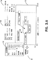
図3. 8及び3. 9は、円パターンを規定するための手順を図示し、そしてかくして、螺旋パターンを規定するための手順を示す図3. 6及び3. 7と類似である。円規定データ入力プロセスはブロック104(図3. 8)において始まり、そこではデータ入力フォームはウィンドウS2(図3. 9)中に図示されている。次に、ユーザは、中心X、Y座標(ブロック106)、半径(ブロック108)、巻きの数及び方向(ブロック110)、経路速度(ブロック112)、スタート位置(ブロック114)、入り口半径及び巻き数(ブロック116)、並びに出口半径及び巻き数(ブロック118)を入力する。ブロック120においては、ユーザは、このパターンを現在のものにすべきかどうかを決定する。そうである場合には、コンピュータは、ブロック122において、パターン規定変数を更新し、そしてパターンをテーブルディスプレイウィンドウS1(図3. 9)中に表示する。
図3. 10及び3. 11は、それぞれ、丸みのある長方形パターン規定手順(ブロック74、図3. 5)のためのプログラムのフローチャート部分及び対応する例示のスクリーンディスプレイである。ブロック124において、丸みのある長方形規定データ入力手順は、データ入力フォームのウィンドウS2(図3. 11)中へのディスプレイから始まる。ブロック126においては、中心X、Y座標を入力する。ブロック128においては、X軸に沿ったパターンの長さを入力する。ブロック130においては、Y軸に沿った長さを入力する。ブロック132においては、コーナー半径を入力する。ブロック134においては、巻きの数を入力する。ブロック136においては、方向を入力する。そして、ブロック138においては、経路速度を入力する。今述べたパラメータの各々に対する例示の値を、図3. 11のスクリーンディスプレイのデータ入力ウィンドウS2中に図示する。テーブルウィンドウS1は、これらのパラメータの各々が本発明の明細書においてどのようにして規定されるかを示す。決定ブロック140(図3. 10)においては、ユーザは、このパターンを現在のものにすべきかどうかを決定する。そうである場合には、コンピュータは、ブロック142に分岐し、そしてパターン規定変数を更新し、そしてパターンをウィンドウS1(図3. 11)中に表示する。
さて図3. 12を参照して説明すると、振動パターン規定手順(ブロック78、図3. 5)はブロック144において始まる。例示の振動ディスプレイスクリーンをスクリーン3. 13中に図示する。ブロック146(図3. 12)において、ユーザは、X、Y座標におけるスタート位置を入力する。ブロック148においては、パターンのX軸長さを入力する。ブロック150においては、パターンのY軸長さを入力する。ブロック152においては、パターンにおけるサイクルの数を入力する。そして、ブロック154においては、経路速度を入力する。これらのパラメータは、図3. 13中に示すように規定される。決定ブロック156においては、ユーザは、このパターンを現在のパターンにすべきかどうかを決定し、そしてそうである場合には、コンピュータは、ブロック158においてパターン規定変数を更新し、そしてパターンをテーブルディスプレイウィンドウS1(図3. 13)中に表示する。
図3. 14は、図3. 3のラン規定データ入力手順48のための手順を図示する。ブロック160において、この手順は、ディスプレイのウィンドウS2(図3. 15)中へのラン規定入力フォームのディスプレイによって始まる。このフォームによって、ユーザは、X方向中のセルの数(ブロック162)及びY方向のセルの数(ブロック164)を入力する。図3. 15の例においては、これらの値の各々は、ウィンドウS1中の表示されたパターンによって映されるように、2である。決定ブロック166においては、ユーザは、これらの入力を現在のものにすべきかどうかを決定する。そうである場合には、コンピュータは、ブロック168において格子規定変数を更新し、そして格子をテーブルディスプレイウィンドウS1(図3. 15)中に表示する。図3. 15は、同一の円パターンの2x2格子の例を示す。
図3. 16及び図3. 17は、図3. 3のレイアウト規定データ入力手順52を詳論する。図3. 16を参照して説明すると、レイアウト規定手順はブロック170において始まり、そこではレイアウト規定メニューが、図3. 17中に示すように、ウィンドウS2中に表示される。ブロック172においては、ユーザは、ディスプレイビューポートのための興味の選択された領域を入力する。ブロック174においては、ディスプレイの活動領域のための座標を入力する。ブロック176においては、ディスプレイのワールド座標系のための単位(ミリメートル又はインチ)を入力する。ブロック178においては、活動領域ディスプレイ格子のためのパラメータ(数、長さ、タイプ)を入力する。ブロック180においては、ラン−時間情報ビューポートのパラメータを入力する。ブロック182においては、引き(draw)だけのモード(このモードにおいては、膜は実際には注型されない)のためのパラメータを入力する。そして、ブロック184においては、自動報告モード(このモードにおいては、プログラムランが自動的に繰り返される)のためのパラメータを入力する。決定ブロック186においては、ユーザは、このレイアウトを現在のレイアウトにすべきかどうかを決定し、そしてそうである場合には、コンピュータは、ブロック188においてレイアウト規定変数を更新し、そして新しいレイアウト規定データに従ってスクリーン全体をリフレッシュする。
図3. 17は、ワールド座標系を変えるための、又はズーミングのための手順と関連した例示のスクリーンディスプレイを図示する。図3. 17のディスプレイと図3. 15のディスプレイとを比較することによって、ディスプレイウィンドウS1に関する座標境界を変えることによって、ユーザはスクリーンの選択された部分を拡大することができることを理解することができる。
図3. 18は、図3. 3のモータ規定手順56を更に図示する。ブロック190においては、モータ規定メニューが表示される。決定ブロック192、196及び200においては、ユーザはPIDのX軸、Y軸、又はθ軸を選択し、そしてコンピュータはそれに応じてブロック194、198又は202の一つに分岐して、PID規定データ入力手順を実施する(図3. 19は、この手順のためのフローチャートを図示する)。決定ブロック204においては、ユーザは、モータを初期化すべきかどうかを決定する。そうである場合には、コンピュータは、そこでモータが停止されるブロック206に分岐し、そして新しく規定されたPID状態にリセットする。
図3. 19を参照して説明すると、PID規定データ入力フォームをブロック208において表示する。ブロック210、212、214、216及び218においては、ユーザは、比例利得、積分利得、積分端、微分利得及び微分サンプル時間係数のためのパラメータ(これらはPID制御パラメータである)を入力する。決定ブロック220においては、ユーザは、正に規定されたPID設定を現在のものにすべきかどうかを決定する。そうである場合には、コンピュータはブロック222においてPID規定変数を更新し、そして新しい規定データに従って特定されたモータコントローラを設定する。
図3. 20は、図3. 3のブロック60のセーブ及びロード手順を図示する。ブロック224においては、セーブ及びロードメニューを表示する。決定ブロック226においては、ユーザはファイルをセーブすべきかどうかを決定し、そしてブロック228においては、ユーザはファイル名を入力し、そしてコンピュータはこのファイルを特定されたファイルにセーブする。決定ブロック230においては、ユーザは特定されたファイルから一つのファイルをロードすべきかどうかを決定する。ブロック232においては、ユーザはファイルを指名し、そしてコンピュータは特定されたファイルをロードする。
図3. 21は、ブロック24〜60のユーザ入力手順が完了した後の、図3. 3の手順の残りのためのフローチャートの部分を図示する。ブロック234においては、コンピュータはモータコントローラを初期化する。ブロック236においては、コンピュータはフォーム及びメニューシステムを閉じる。ブロック238においては、コンピュータはスクリーンをクリアしそしてコンピュータ中の関係した図形カードをテキストにリセットする。そして、ブロック240においては、コンピュータは操作システムに出る。
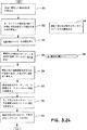
図3. 22〜3. 25は、図3. 3のブロック28のステップ アンド リピートの現在のパターン手順を図示する。この手順はブロック250(図3. 22)において始まる。ブロック252においては、現在の格子位置に関するX及びYオフセットを計算する。ブロック254においては、セルの縁に沿った最短経路を使用してダイをセル原点まで動かす。ステップ256においては、コンピュータは円パターンが既に要求されたかどうかを決定する。そうである場合にはコンピュータはブロック258に分岐する。同様に、ステップ260、264及び268においては、コンピュータは螺旋パターン、丸みのある長方形パターン、又はその他のタイプのパターンが既に要求されたかどうかを決定し、そしてそれに応じてブロック262、266又は270の適切な一つに分岐する。(ブロック258、262、266及び270はお互いに類似であり、それ故本明細書中ではブロック258だけを更に説明することに注目せよ。これは図3. 23〜3. 25を参照して行う)。決定ブロック272においては、コンピュータは限界を越えた(overlimit)エラーが検出されたかどうかを決定し、そしてそうである場合にはブロック274に分岐するが、そこではモータを停止しそして警告メッセージを表示する。決定ブロック276においては、プログラムはキーボードオーバーライドが起きたかどうかを検出し、そしてそうである場合には決定ブロック280に分岐するが、そこではコンピュータはオーバーライドが拡張であったかどうかを決定する。拡張が要求された場合には、ブロック282を実行しそしてすべてのモータを停止する。オーバーライドが拡張ではなかった場合には、ブロック284において、コンピュータはオーバーライドが出口ホーム命令であったかどうかを決定する。そうである場合には、ブロック286においてすべてのモータを停止し、そしてブロック288の手順を実行する、即ちHMRI_find_home及びHMRI_home_thetaはそれぞれモータをX、Y=0及びθ=0に設定する。決定ブロック290においては、コンピュータはオーバーライドが次のセルへ動く要求であったかどうかを検出し、そしてそうである場合にはブロック252に分岐する。ブロック276においてオーバーライドが検出されなかった場合には、コンピュータはブロック278に分岐するが、そこではそれは次のセル又は格子が要求されたかどうかを決定し、そしてそうである場合にはブロック252に分岐する。
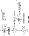
図3. 23〜3. 25は、図3. 22のブロック258のHMRI_spiral手順のためのフローチャートの部分を図示する。この手順はブロック300(図3. 23)において始まる。ブロック302においては、各々のモータの加速をモータコントローラによって最大に設定する。ステップ304においては、HMRI_move手順を実行するが、そこではX、Yモータがダイをそのスタート位置に動かす。ブロック306においては、θモータをユーザが規定したスタート角度に設定する。決定ブロック308においては、コンピュータは2つの軸の動きが完了するまで待つ。ブロック310においては、コンピュータは、パターンがトレースされるべき方向、即ち、螺旋の動きが外側から中へか又は内側から外へかのどちらなのかを示す論理トグルを設定する。ブロック312においては、コンピュータは、ユーザが規定したスタート半径に対する参照半径を設定する。ブロック314においては、コンピュータはθ増分速度をその最大値に設定する。ブロック316においては、コンピュータは、1度の回転あたりの半径の変化の量を計算する。ブロック318は、最大半径がスクリーンの上に表示されることを示す。
さて図3. 24を参照して説明すると、ブロック320においては、コンピュータは半径に依存した動き増分を計算する。(この増分は以下のように説明することができる。流体は一定速度でノズルから流れるので、ノズルの線又は経路速度もまた一定に保持されなければならない。それ故、ノズルの角速度はパターンの半径が増加又は減少するにつれて変化し、そしてθの変化の速度はそれに応じて調節されなければならない。“半径に依存した動きの増分”は、経路半径の関数としてノズルのθ位置を調節する際に使用される)。ブロック322においては、初期のθ増分を、X、Y増分及び時計/反時計方向標識を使用して計算する。ブロック324においては、速度測定タイマーを初期化する。ブロック326においては、螺旋の上の現在のターゲットX及びY座標(次の所望の位置)を計算する。ブロック328においては、すべての巻き及び層が引かれるまで基本パターンを繰り返す。ブロック330においては、規定された経路速度((VX 2+VY 2)1/2)を得るために現在の成分(VX、VY)速度を計算する。ブロック332においては、成分速度及びターゲットX、Y座標をモータコントローラ単位(即ち、エンコーダカウント)に変換する。ブロック334においては、X、Y及びθモータコントローラを規定されたベクトルに関して設定する。ブロック336においては、X、Y及びθモータを現在の増分のためにスタートさせる。
図3. 25を参照して説明すると、決定ブロック340においては、コンピュータは3つの軸の動きの完了を待つ。ブロック342においては、現在の半径を基にして新しい増分値を計算する。決定ブロック344においては、コンピュータは何らかのユーザキーストローク変更が起きたかどうかを決定する(ユーザはキーボードによってある種のパラメータに対して実時間制御を行うことができることに注目せよ、例えば、モータ速度は矢印キーによって調節することができる)。そうである場合には、ブロック350において、それはユーザが何を要求したかを決定する(拡張、出口、又は次)。ブロック352においては、コンピュータは、ユーザが経路速度、線速度(即ち、注型格子のセルの間を動く際のダイの速度)、又は半径を要求したかどうかを決定する。これらの一つが選択された場合には、プログラムはブロック354に分岐し、そしてキーが押された時間によって決定される、キーストロークカウントによって指示されるパーセントだけ選択されたパラメータを変える。決定ブロック344において変化が要求されなかった場合には、コンピュータは決定ブロック346に進み、そしてすべての巻き及び層が完了したかどうかを決定する。そうでない場合には、それは、図3. 26のループ328に対応する巻き及び層ループ356に分岐する。
要約すると、本発明は、コンピュータ制御された中空繊維膜注型システムを提供する。コンピュータはDCサーボモータを制御して注型ダイを3つの軸(X、Y、θ)に沿って動かし、そしてかくして壁厚さを含む最後の膜の形を制御する。凝固速度は溶媒によって改変されて粘性の抗力(drag)による膜生成のための適切な時間を可能にする。膜が注型されている時に膜の動き又はドリフトを制限するために、マンドレル又はガイドブロックを浴の中で使用することができる。
本明細書は、コンピュータの操作、例えば特定のユーザインターフェイス手順をかなり詳細に述べ、そして特別なハードウェア(モータ、コントローラなど)を詳記しているけれども、本発明の本当の範囲は、それらの特別なハードウェア又はソフトウェア要素に限定されない。加えて、本発明のコンピュータ制御された注型システムは、種々のポリマー、コポリマー又はこれらの組み合わせを基にした種々の異なる中空繊維膜の製造のために使用することができることが当業者には明らかであろう。本発明の一つの実施態様を、図3. 7中に図示された種類の螺旋コイル形を有する、そして約0.1〜10.0ミリメートル、好ましくは4〜7ミリメートルの範囲の内径、及び約25〜500マイクロメートル、好ましくは100〜200マイクロメートルの範囲の壁厚さを有する中空繊維膜を作るために使用した(しかしながら、本発明は、特別な形、径又は壁厚さの繊維を注型することに限定されない)。上で引用した米国特許第5,002,661号中で述べられたように、このような中空繊維コイルは、人工膵臓の範疇において殊に有用である。This is a continuation-in-part application of co-pending U.S.S.N.07 / 831,142 (Milliken and Barnes) filed February 4, 1992.
Field of Invention
The present invention relates generally to a method and apparatus for producing a tubular hollow fiber membrane, and more particularly to a computer controlled machine for automatically casting a hollow fiber membrane.
Background of the Invention
The present invention deals with manufacturing methods for casting various shapes of tubular hollow fiber membranes, for example membranes having a tubular shape of 6 mm diameter with a wall thickness of 0.125 millimeters (mm). Such membranes can be used in artificial pancreas, as described by Chick et al. In US Pat. No. 5,002,661 issued May 26, 1991. However, these membranes are very fragile and difficult to mold. It is particularly difficult to form tight coils and spiral shapes with such a wall-to-diameter ratio.
A known casting method involves forcing a polymeric fluid from the annular orifice of a nozzle of a coextrusion die while forcing a coagulating fluid from the center core of the nozzle. A phase reversal process occurs at the point of contact between these two fluids. As a result, the polymeric fluid solidifies and produces a tubular structure. The solidification rate of the tubular structure is tempered by the solvent in the solidification fluid, which allows some manipulation of the fibers before final curing occurs. There is a large bath of water a few millimeters below the extrusion die. When the resulting tubular structure is immersed in this bath, further solidification begins there and is shaped into the desired shape before it will become fully solidified.
In certain applications, it may be desirable to use a hollow fiber membrane of a particular shape or shape, for example helical or coiled. However, it is important that no distortions or crimps occur on the membrane walls.
Summary of invention
Accordingly, it is an object of the present invention to provide an automated system for casting hollow fiber membranes into various defined shapes, such as spirals, lines, circles, rectangles and the like. In addition, the system must be efficient and provide a high level of reproducibility. It would also be advantageous to have the ability to change shape during casting (on the fly), which would increase system productivity.
In order to achieve these goals, it was decided to move the nozzle above the static coagulation bath. In a preferred embodiment, a computer is used to control the movement of the nozzle in a plane parallel to the static coagulation bath in order to produce a membrane having the desired shape. Casting is complicated by the fact that the nozzle must always be oriented in a way that would compensate for distortions that occur in the wall thickness. Such distortion is caused by bending of the membrane as it is being cast. Unless the extrudate flow pattern is adjusted to supply more polymer to the outside than to the inside of the curve, the outer fibers of the structure are stretched and the inner fibers are compressed, which is thinner than the inner walls. Bring the wall. To compensate for this, the nozzle ring is offset to make part of the ring a little thicker than the opposite part in that the fluid exits the nozzle. In accordance with the present invention, nozzle orientation is controlled such that more polymer is fed along the outer edge of the membrane-curved section than along the inner edge. This results in a uniformly symmetric wall thickness. In a preferred embodiment, a third axis of rotation called “seater” (θ) is included in the control program (“seater” and “θ” are used interchangeably in this specification and the accompanying drawings. ) When the nozzle is moved along a radius, for example through an angle of 90 °, the nozzle is rotated by 90 ° in the same direction, but this rotation is aligned as the turn is made.
Accordingly, the method encompassed by the present invention comprises: (a) forcing the polymeric fluid from the annular orifice of the nozzle of the coextrusion die while forcing the coagulated fluid from the center core of the nozzle; (B) controlling the movement of the nozzle in a plane above and parallel to the surface of the coagulation bath so as to produce a hollow fiber membrane of defined shape in the bath. While automatically carrying out the steps of performing. In a preferred embodiment, step (b) comprises the coordinated movement of said nozzle about at least three axes, X, Y and θ, in order to cast a hollow fiber membrane of substantially uniform wall thickness. Performing. In accordance with the present invention, the polymeric fluid is extruded through an annular orifice that is offset within the nozzle, and the nozzle can be rotated about the θ axis in line with movement along the X and Y axes. The movement of the nozzle can advantageously be carried out according to the offset of the annular orifice and the viscosity of the polymeric fluid. In one preferred embodiment, the method of the present invention is adapted to cast hollow fiber membranes having an inner diameter of about 4-7 millimeters and a wall thickness of about 100-200 micrometers. Of course, the present invention can also achieve other region diameters and wall thicknesses.
The apparatus according to the present invention comprises a coextrusion die having a nozzle with an offset annular orifice and a center core (core), forcibly extruding a polymer fluid from the annular orifice, while coagulating fluid from the center core (heart). Means for forcibly extruding, as well as above and parallel to the surface of the bath, while controlling the movement of the nozzle so as to produce a hollow fiber membrane of defined shape in the coagulation bath. Means for performing the above-mentioned steps, including means for automatically moving said nozzle in a plane.
In addition, the present invention provides a computer storage medium (e.g., computer disk, tape) in which are coded instructions (software) for control of a system for automatically casting a hollow fiber membrane. Include. The system includes a coextrusion die having X, Y and θ servo motors operatively connected to a computer via at least one servo driver, a tab for holding a coagulation bath, and an offset annular orifice. including. The software according to the invention allows the movement of the nozzle (including rotation) in a plane above and parallel to the surface of the coagulation bath to produce a defined shape of the hollow fiber membrane. It includes code for performing automatically while controlling.
By using different computer algorithms, we have successfully produced coils, spirals, straight lines and other shapes. The computer controls the shape and matches the acceleration, speed, displacement and positioning of the nozzles to match different polymer viscosity and solvent concentration requirements. The movements of X, Y and θ are calculated during flight and are therefore easy to make shape changes. Once the accepted shape is achieved, the associated parameters can be stored for future recall. Other features of the invention are discussed below in connection with the detailed description of the preferred embodiments.
[Brief description of the drawings]
FIG. 1 illustrates a membrane casting system embodying the present invention.
FIG. 2 illustrates the coordinated movement of the coextrusion die or nozzle according to the present invention with respect to the X, Y and θ axes.
Figures 3.1 to 3.25 illustrate a flow chart of a computer program for controlling a membrane casting system according to the present invention and a screen display of related descriptions.
Detailed Description of the Preferred Embodiment
As discussed above, the membrane casting system of the present invention is a coextrusion die having a nozzle with an offset annular orifice, forcing the polymeric fluid from the annular orifice while coagulating from the center core. Means for forcing the fluid and means for automatically moving the nozzle above the coagulation bath. The movement of the nozzle is automatically controlled by a pre-programmed computer to produce a defined shape hollow fiber membrane.
FIG. 1 illustrates one embodiment of the membrane casting system of the present invention. This particular embodiment includes servomotors 1A, 1B and 1C in the X, Y and θ directions, each of which is coupled to an associated
FIG. 2 shows how the movement of the coextrusion die 10 in the X, Y and θ directions is aligned so that the front face of the die is held in a fixed position with respect to the path followed when casting the fiber. This is illustrated. As mentioned above, this coordinated movement causes the system to cast a uniform thickness of hollow fiber membrane as the polymeric fluid is extruded through an offset annular orifice in the nozzle. Enable. The nozzle movement can be advantageously performed to maintain a constant fluid flow rate, but the fluid flow rate is a function of the offset of the annular orifice and the viscosity of the polymeric fluid.
Figures 3.1 to 3.25 illustrate a flow chart for programming the
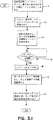
Figure 3.1 shows the initial setup part of the program. First, in block 11, the system loads the default destination file. The default object file contains data defining the default (or estimated) layout, pattern, repetitive grid, and motor control parameters. ("Layout" is the manner in which the image of the casting table is mapped to the computer screen. The grid is a series of lines drawn on the screen to divide the casting window into cells, where each Pattern is drawn once in each cell). In
Before continuing the description of the operation of the
Referring now to FIGS. 3.3 and 3.4, the computer continues to operate at block 24 (FIG. 3.3) where the main menu is displayed and the system waits for user input. As shown in Figure 3.4, the main menu is displayed in region S2 (menu and form window) and includes the following selections: Start the run, position θ (the θ position where the die is selected) ), Position X and Y (move the die to the selected X, Y position), home (move the die to a fixed position in X, Y and θ), define the pattern, define the run grid Define the layout, define the motor and load / save. These options are indicated by decision blocks 26, 30, 34, 38, 42, 46, 50, 54 and 58 in Figure 3.3, respectively. An exemplary circle pattern of 2.14 rolls and a length of 147.15 mm is displayed in the activity casting window S1 of FIG. 3.4 as reflected by the real time information window S4. In addition, the real-time mode window S5 shows a path speed of 94.35 millimeters per second, and the assistance window S3 has function keys and their corresponding functions (exit, exit-home, skip cell, pause-resume, line, tangent And radius). These functions are not described in detail herein because they are well known in the art and are not part of the claimed invention.
Referring to Figure 3.3, when a user selects a desired function, the computer branches accordingly to one of the following blocks:
28 Step and repeat the current pattern (this block is described later with reference to Figure 3.24).
32 Set the head angle, here the user uses the arrow keys to set the die angle.
36 Set the X and Y positions, here the user uses the arrow keys to set the die to the selected X, Y position.
40 Find the home, where the table is scanned in the X and Y directions until the home switch is found.
44 Pattern definition (this block is described below with reference to Figure 3.5).
48 Specified data input (this block will be explained later with reference to Figure 3.14 and 3.15).
52 Layout definition data input (This block will be described later with reference to Figures 3.16 to 3.19).
56 Motor specification (this block will be explained later with reference to Figure 3.20).
60 Save / Load (this block is described later with reference to Figure 3.22).
Referring to Figure 3.5, the pattern definition operation begins at
66 Spiral rules,
70 yen rule,
74 Rounded rectangle regulations,
78 Vibration regulation,
80 Reset the graphic display.
The
Now referring to 3.6, the spiral prescription data entry procedure begins at block 84. In
Figures 3.8 and 3.9 illustrate the procedure for defining the circular pattern and thus are similar to Figures 3.6 and 3.7 showing the procedure for defining the spiral pattern. The circle definition data entry process begins at block 104 (Figure 3.8), where the data entry form is illustrated in window S2 (Figure 3.9). Next, the user selects the center X, Y coordinate (block 106), radius (block 108), number and direction of winding (block 110), path speed (block 112), start position (block 114), entrance radius and winding. Enter the number (block 116) and the exit radius and number of turns (block 118). In
FIGS. 3.10 and 3.11 are the flowchart portion of the program for the rounded rectangular pattern definition procedure (block 74, FIG. 3.5), respectively, and the corresponding exemplary screen display. At block 124, the rounded rectangle-defined data entry procedure begins with a display into window S2 of the data entry form (Figure 3.11). In
Referring now to FIG. 3.12, the vibration pattern definition procedure (block 78, FIG. 3.5) begins at
FIG. 3.14 illustrates the procedure for the run specification
FIG. 3.16 and FIG. 3.17 detail the layout definition
FIG. 3.17 illustrates an exemplary screen display associated with a procedure for changing the world coordinate system or for zooming. By comparing the display in Figure 3.17 with the display in Figure 3.15, it will be understood that by changing the coordinate boundary for display window S1, the user can enlarge the selected portion of the screen. it can.
FIG. 3.18 further illustrates the
Referring to FIG. 3.19, a PID specified data entry form is displayed at
Figure 3.20 illustrates the save and load procedure for block 60 of Figure 3.3. In
FIG. 3.21 illustrates the portion of the flowchart for the remainder of the procedure of FIG. 3.3 after the user input procedure of blocks 24-60 has been completed. In
Figures 3.2 to 3.25 illustrate the current pattern procedure for step and repeat of
FIGS. 3.23-3.25 illustrate portions of the flowchart for the HMRI_spiral procedure of block 258 of FIG. 3.22. This procedure begins at block 300 (Figure 3.23). In
Referring now to FIG. 3.24, at
Referring to FIG. 3.25, at
In summary, the present invention provides a computer controlled hollow fiber membrane casting system. The computer controls the DC servo motor to move the casting die along the three axes (X, Y, θ) and thus control the shape of the final film, including the wall thickness. The solidification rate is modified by the solvent to allow an appropriate time for film formation by viscous drag. A mandrel or guide block can be used in the bath to limit membrane movement or drift as the membrane is cast.
Although this specification describes computer operations, such as specific user interface procedures, in considerable detail and details specific hardware (motors, controllers, etc.), the true scope of the present invention is limited to those specific It is not limited to simple hardware or software elements. In addition, it will be apparent to those skilled in the art that the computer controlled casting system of the present invention can be used for the manufacture of a variety of different hollow fiber membranes based on a variety of polymers, copolymers, or combinations thereof. Will. One embodiment of the present invention has a helical coil shape of the type illustrated in FIG. 3.7 and has an inner diameter in the range of about 0.1-10.0 millimeters, preferably 4-7 millimeters, and about 25-500 micrometers. Used to make hollow fiber membranes having a wall thickness in the range of meters, preferably in the range of 100-200 micrometers (however, the present invention is directed to casting fibers of special shape, diameter or wall thickness Not limited). As described in US Pat. No. 5,002,661, cited above, such hollow fiber coils are particularly useful in the category of artificial pancreas.
Claims (3)
(b)凝固浴の表面の上方のそしてそれに平行な面の中での該ノズルの動きを、規定された形の中空繊維膜を前記の浴の中で生成させるように前記の動きを制御しながら、自動的に遂行すること
のステップを含んで成る、規定された形の中空繊維膜を自動的に注型するための方法。(A) forcing the polymer fluid from the annular orifice of the nozzle of the coextrusion die while forcing the coagulation fluid from the center core (core) of the nozzle; and (b) above the surface of the coagulation bath. And automatically performing the movement of the nozzle in a plane parallel to it while controlling the movement so as to produce a hollow fiber membrane of defined shape in the bath. A method for automatically casting a hollow fiber membrane of defined shape comprising:
(b)該ノズルの該環状オリフィスからポリマー状流体を無理に押出し一方該センターコア(心型)から凝固流体を無理に押出すための手段、並びに
(c)規定された形の中空繊維膜を凝固浴の中で生成させるように該ノズルの動きを制御しながら、前記凝固浴の表面の上方のそしてそれに平行な面の中で該ノズルを自動的に動かすための手段
を含んで成る、規定された形の中空繊維膜を自動的に注型するための装置。(A) a coextrusion die having a nozzle with an offset annular orifice and a center core (core);
(B) means for forcibly extruding a polymer fluid from the annular orifice of the nozzle while forcibly extruding a coagulated fluid from the center core (core), and (c) a hollow fiber membrane of a defined shape A means for automatically moving the nozzle in a plane above and parallel to the surface of the coagulation bath while controlling the movement of the nozzle to be generated in the coagulation bath; For automatically casting hollow fiber membranes in the shape of
Applications Claiming Priority (3)
| Application Number | Priority Date | Filing Date | Title |
|---|---|---|---|
| US07/984,829 | 1992-12-03 | ||
| US07/984,829 US5298206A (en) | 1992-02-04 | 1992-12-03 | Method and apparatus for casting hollow fiber membranes |
| PCT/US1993/011731 WO1994012333A1 (en) | 1992-12-03 | 1993-12-03 | Casting hollow fiber membranes |
Publications (2)
| Publication Number | Publication Date |
|---|---|
| JPH08507263A JPH08507263A (en) | 1996-08-06 |
| JP3638601B2 true JP3638601B2 (en) | 2005-04-13 |
Family
ID=25530925
Family Applications (1)
| Application Number | Title | Priority Date | Filing Date |
|---|---|---|---|
| JP51349994A Expired - Fee Related JP3638601B2 (en) | 1992-12-03 | 1993-12-03 | Method and apparatus for casting hollow fiber membranes |
Country Status (6)
| Country | Link |
|---|---|
| US (1) | US5298206A (en) |
| EP (1) | EP0674576A1 (en) |
| JP (1) | JP3638601B2 (en) |
| AU (1) | AU5737794A (en) |
| CA (1) | CA2150941A1 (en) |
| WO (1) | WO1994012333A1 (en) |
Families Citing this family (10)
| Publication number | Priority date | Publication date | Assignee | Title |
|---|---|---|---|---|
| US6447279B1 (en) | 1998-04-10 | 2002-09-10 | Guill Tool & Engineering Co., Inc. | Extrusion die with rotating components |
| US8240356B2 (en) * | 2004-10-12 | 2012-08-14 | Efficient Manufacturing Systems Integration | Apparatus and method for simultaneous usage of multiple die casting tools |
| US7216692B1 (en) * | 2004-10-12 | 2007-05-15 | Efficient Manufacturing Systems, Llc | Apparatus and method for simultaneous usage of multiple die casting tools |
| EP1693178A1 (en) * | 2005-02-22 | 2006-08-23 | Advanced Elastomer Systems, L.P. | Tubular Free-Shaped Article |
| WO2008040943A2 (en) * | 2006-10-02 | 2008-04-10 | The Queen's University Of Belfast | Improvements relating to the measurement of viscosity |
| DE102007019051B3 (en) * | 2007-04-23 | 2008-10-09 | Fresenius Medical Care Deutschland Gmbh | Hollow fiber capillary membrane and process for its preparation |
| KR20140107964A (en) * | 2013-02-28 | 2014-09-05 | 삼성전기주식회사 | Electrospinning apparatus |
| CN107988639A (en) * | 2017-12-27 | 2018-05-04 | 厦门大学 | High efficiency filter nanofiber membrane preparation device |
| US10889915B2 (en) * | 2018-01-31 | 2021-01-12 | Saudi Arabian Oil Company | Producing fibers using spinnerets |
| CN110484983A (en) * | 2019-08-27 | 2019-11-22 | 广东工业大学 | A kind of electrostatic spinning solution injection device |
Family Cites Families (6)
| Publication number | Priority date | Publication date | Assignee | Title |
|---|---|---|---|---|
| GB1566581A (en) * | 1975-12-29 | 1980-05-08 | Nippon Zeon Co | Hollow fibres and methods of manufacturing such fibres |
| JPS5584412A (en) * | 1978-12-20 | 1980-06-25 | Nippon Zeon Co Ltd | Production of hollow fiber |
| JPS59188422A (en) * | 1983-04-12 | 1984-10-25 | Meiji Gomme Kasei:Kk | Method for molding automatically bent tube |
| JPH0698689B2 (en) * | 1988-11-11 | 1994-12-07 | 松下電工株式会社 | Method for manufacturing optical model |
| US5002661A (en) * | 1989-08-25 | 1991-03-26 | W. R. Grace & Co.-Conn. | Artificial pancreatic perfusion device |
| IT1248093B (en) * | 1991-06-20 | 1995-01-05 | Eniricerche Spa | MODIFIED POLE (2,6-DIMETHYL-P-OXYPHENYLENE) HOLLOW FIBERS |
-
1992
- 1992-12-03 US US07/984,829 patent/US5298206A/en not_active Expired - Fee Related
-
1993
- 1993-12-03 CA CA002150941A patent/CA2150941A1/en not_active Abandoned
- 1993-12-03 WO PCT/US1993/011731 patent/WO1994012333A1/en not_active Application Discontinuation
- 1993-12-03 EP EP94903422A patent/EP0674576A1/en not_active Ceased
- 1993-12-03 JP JP51349994A patent/JP3638601B2/en not_active Expired - Fee Related
- 1993-12-03 AU AU57377/94A patent/AU5737794A/en not_active Abandoned
Also Published As
| Publication number | Publication date |
|---|---|
| EP0674576A4 (en) | 1995-10-25 |
| CA2150941A1 (en) | 1994-06-09 |
| AU5737794A (en) | 1994-06-22 |
| EP0674576A1 (en) | 1995-10-04 |
| WO1994012333A1 (en) | 1994-06-09 |
| JPH08507263A (en) | 1996-08-06 |
| US5298206A (en) | 1994-03-29 |
Similar Documents
| Publication | Publication Date | Title |
|---|---|---|
| JP3638601B2 (en) | Method and apparatus for casting hollow fiber membranes | |
| US6814907B1 (en) | Liquifier pump control in an extrusion apparatus | |
| JP5266169B2 (en) | Method and system for automated software control of waterjet orientation parameters | |
| US6028410A (en) | Resonance detection and resolution | |
| DE69828530T2 (en) | LASER NOZZLE ASSEMBLED ON A CAR AND METHOD FOR LASER POSITIONING CONTROL | |
| EP1427578A1 (en) | Melt flow compensation in an extrusion apparatus | |
| CN108958173B (en) | S curve acceleration and deceleration planning method based on trapezoidal solution and under any displacement speed | |
| CN111727411B (en) | Equipment motion control method, equipment and storage device | |
| JPH06274228A (en) | Numerical control device | |
| US20220331904A1 (en) | 3d printing apparatus, 3d printing method, and machine learning device | |
| CN116291519A (en) | Axis control method for unmanned autonomous tunneling of shield tunneling machine | |
| CN113526232B (en) | Method for high-precision ground-cushion yarn laying of yarn during bobbin winding | |
| JP3315837B2 (en) | Extruder control device | |
| US5055753A (en) | Programmable servomotor coil winder | |
| CN114115125B (en) | Method for budget axis positioning process | |
| CN117687417A (en) | Industrial robot external motion trail planning method and system | |
| CN110142069B (en) | Micro-channel chip processing method based on micro-nano technology | |
| JPH04111490A (en) | Direct drawer | |
| CN116382361A (en) | Acceleration continuous real-time position planning control method | |
| CN111786593B (en) | Ultrasonic motor accurate positioning control method based on machine learning | |
| JP2606253B2 (en) | Method of forming laminated T-tube made of FRP | |
| JPH0447308A (en) | Positioning control device for motor valve | |
| JP2606251B2 (en) | Method of forming laminated T-tube made of FRP | |
| CN116165900A (en) | Self-adaptive single-joint servo PID control method for convolutional neural network deep learning | |
| CN117283546A (en) | Yarn track prediction method and system in special-shaped structure mandrel knitting process |
Legal Events
| Date | Code | Title | Description |
|---|---|---|---|
| A601 | Written request for extension of time |
Free format text: JAPANESE INTERMEDIATE CODE: A601 Effective date: 20040107 |
|
| A602 | Written permission of extension of time |
Free format text: JAPANESE INTERMEDIATE CODE: A602 Effective date: 20040223 |
|
| A02 | Decision of refusal |
Free format text: JAPANESE INTERMEDIATE CODE: A02 Effective date: 20040601 |
|
| A521 | Request for written amendment filed |
Free format text: JAPANESE INTERMEDIATE CODE: A523 Effective date: 20040830 |
|
| A521 | Request for written amendment filed |
Free format text: JAPANESE INTERMEDIATE CODE: A523 Effective date: 20041125 |
|
| A911 | Transfer to examiner for re-examination before appeal (zenchi) |
Free format text: JAPANESE INTERMEDIATE CODE: A911 Effective date: 20041216 |
|
| TRDD | Decision of grant or rejection written | ||
| A01 | Written decision to grant a patent or to grant a registration (utility model) |
Free format text: JAPANESE INTERMEDIATE CODE: A01 Effective date: 20050104 |
|
| A61 | First payment of annual fees (during grant procedure) |
Free format text: JAPANESE INTERMEDIATE CODE: A61 Effective date: 20050112 |
|
| R150 | Certificate of patent or registration of utility model |
Free format text: JAPANESE INTERMEDIATE CODE: R150 |
|
| LAPS | Cancellation because of no payment of annual fees |