JP3638221B2 - Fork type parking system - Google Patents
Fork type parking system Download PDFInfo
- Publication number
- JP3638221B2 JP3638221B2 JP32389998A JP32389998A JP3638221B2 JP 3638221 B2 JP3638221 B2 JP 3638221B2 JP 32389998 A JP32389998 A JP 32389998A JP 32389998 A JP32389998 A JP 32389998A JP 3638221 B2 JP3638221 B2 JP 3638221B2
- Authority
- JP
- Japan
- Prior art keywords
- parking
- car
- transport
- carriage
- parking tower
- Prior art date
- Legal status (The legal status is an assumption and is not a legal conclusion. Google has not performed a legal analysis and makes no representation as to the accuracy of the status listed.)
- Expired - Fee Related
Links
Images


Description
【0001】
【発明の属する技術分野】
本発明は、n基のエレベータ式の駐車塔を連続的に設置して、自動車の収容台数の拡大を図るフォーク式立体駐車装置に関する。
【0002】
【従来の技術】
従来、この種の立体駐車装置の一例が特公平7−81417号公報に開示されている。この立体駐車装置の場合、図7に示すように、第1、第2の駐車塔101、102を備え、これらが前後縦列に連続して設置されている。各駐車塔101、102には、地上1階にエレベータの着床位置を設定されたエレベータの昇降路110が形成されていて、そこにフォーク式のエレベータ111が据え付けられて、図8に示すように、フォーク状の昇降ステージ112が昇降されるようになっている。また、図7において、エレベータの昇降路110の両側に沿って階層状に複数の駐車区画113が設けられ、これらの駐車区画113にそれぞれ、図示されないフォーク式の横行台車がその横行駆動装置によりエレベータの昇降路110に向けて横行可能に配置されている。
【0003】
第1の駐車塔101の地上1階部分は自動車の乗込部103になっていて、図9に示すように、エレベータ111の着床位置下方に形成されたピット104内に自動車の方向変換装置105が設置されている。この方向変換装置105は、フォーク式の旋回板106と、その昇降旋回装置107とを備える。第2の駐車塔102の地上1階部分は、図8に示すように、エレベータの昇降路110の両側に駐車区画113が形成されて、そこに横行台車114が横行可能に配置されている。
【0004】
また、図9に示すように、第1の駐車塔101の自動車の乗込部103のピット104は、第2の駐車塔102のエレベータ111の着床位置の下方まで、連続的に形成されていて、このピット104上に自動車の搬送装置108が設置されている。搬送装置108は、ピット104の底面上に配置され、旋回板106とその昇降旋回装置107の上部とを切り離して移動案内するガイドローラ115と、駆動用のモータ116と、昇降旋回装置107の上部とモータ116との間に連結されたチェーン117とを備え、この装置により、旋回板106とその昇降旋回装置107の上部とを第1、第2の駐車塔101、102間で往復移動する。
【0005】
自動車を入庫する場合は、図7において、まず第1の駐車塔101の乗込部103に自動車を前進で乗り入れ、そこに予め待機中のエレベータ111の昇降ステージ112に乗り込む。この自動車を第1の駐車塔101に格納する場合は、第1の駐車塔101のエレベータ111が上昇駆動され、自動車が昇降ステージ112に支持されて上方の駐車区画113へ移送される。また、この自動車を第2の駐車塔102に格納する場合は、第1の駐車塔101のエレベータ111の下降駆動により、昇降ステージ112がピット104内に下げられ、自動車が方向変換装置105の旋回板106上に受け渡しされる。続いて、図9に示すように、搬送装置108の駆動により、旋回板106とともにその昇降旋回装置107の上部が第1の駐車塔101から第2の駐車塔102へ移動されて、旋回板106上の自動車が第2の駐車塔102へ移送される。第2の駐車塔102では、エレベータ111が上昇駆動され、自動車が昇降ステージ112に支持されて上方の駐車区画113へ移送される。または、昇降ステージ112から1階部分の駐車区画113へ格納される。
【0006】
また、第1、第2の駐車塔101、102から自動車を出庫する場合は、入庫の動作の逆の動作になり、自動車の乗込部103で、方向変換装置105の旋回板106がその昇降旋回装置107により180°旋回され、自動車のフロントが入出庫口に向けられる。自動車が前進で自動車の乗込部103から出庫される。
【0007】
【発明が解決しようとする課題】
この種の立体駐車装置では、立体空間を有効に活用し、第1、第2の駐車塔を縦列に連続して設置することにより、自動車の収容台数を増大し、1基の場合に比べて2倍以上に拡大している。したがって、n基の駐車塔を連続して設置することで、自動車の収容台数をn倍以上に拡大することができる。しかしながら、例えば4基の駐車塔を縦列に設置した場合、自動車の乗込部と各駐車塔との間の距離が長くなり、自動車の入出庫を迅速に行うためには、自動車の搬送速度を高める必要がある。従来の搬送装置のような、旋回板をその昇降旋回装置の一部とともにチェーンで引っ張る方式では、この速度の点で十分に対応することができない。このようにn基の駐車塔を連続して設置することにより自動車の収容台数を拡大しても、それに応じて自動車のより迅速な入庫動作、より迅速な出庫動作が要求されている。
【0008】
本発明は、このような従来の問題を解決するものであり、n基のフォーク式の駐車塔を縦列に連続して設置することにより自動車の収容台数の拡大を図るとともに、自動車の入出庫部と各駐車塔との間の自動車の搬送速度を高めて、自動車の入出庫を円滑、かつ迅速に行い得る優れたフォーク式立体駐車装置を提供することを目的とする。
【0009】
【課題を解決するための手段】
上記目的を達成するために、n基のエレベータ式の駐車塔を縦列に連続して設置し、その両端の駐車塔の一方に自動車の入庫部を備え、他方に自動車の出庫部を備えるとともに、これら入出庫部間の各駐車塔間に搬送台車の搬送路とその退避路とを形成して、この搬送路上にフォーク状の固定ステージを搭載した自走式の搬送台車を任意の台数だけ配置し、往復走行させるようにしている。
【0010】
本発明によれば、自動車の収容台数の拡大を図るとともに、自動車の入出庫部と各駐車塔との間の自動車の搬送速度を高めて、自動車の入出庫を円滑、かつ迅速に行い得る優れたフォーク式立体駐車装置が得られる。
【0011】
【発明の実施の形態】
本発明の請求項1に記載のフォーク式立体駐車装置は、自動車をフォーク状の昇降ステージに載せて昇降するエレベータと、その昇降路に沿って階層状に形成された複数の駐車区画と、各駐車区画に配置されたフォーク状の横行台車と、これらの横行台車を横行する横行駆動装置とを備え、自動車をエレベータと横行台車との間で受け渡しする形式の駐車塔を複数連設したフォーク式立体駐車装置において、前記連接した駐車塔のうち、一端部の駐車塔に自動車の入庫部を有するとともに他端部の駐車塔に出庫部を有し、前記入庫部及び出庫部を有する駐車塔を含む前記各駐車塔間に一対の走行レールが敷設されて、自動車を前記エレベータとの間で受け渡し可能なフォーク状の固定ステージを有する複数の自走式の搬送台車が往復移動し、自動車を前記入庫部を有する駐車塔から前記出庫部を有する駐車塔までの各駐車塔間を搬送する搬送路と、前記入庫部及び出庫部を有する駐車塔以外の任意の駐車塔に形成され、前記各搬送台車が前記搬送路から退避可能な退避路とを備え、前記退避路は前記搬送路の走行レールが分断されて、その分断部に前記走行レールを直交方向に横断して、前記走行レールと平行な2組の一対の可動レールが移動可能に配置され、前記2組の一対の可動レールの一方が前記走行レールから退避されると、他方が前記走行レールに連続的に配置されて前記走行レールの一部を形成するものである。
【0013】
本発明の請求項2に記載のフォーク式立体駐車装置は、請求項1の構成において、2組の一対の可動レールは、スライド機構上に支持され、スライド機構は、前記可動レールを支持する支持フレームと、この支持フレームに軸支された複数のローラと、走行レールの下方でその直交方向に敷設され、支持フレームを横行案内する一対の退避レールと、支持フレームを退避駆動する支持フレーム駆動装置とを備える。
【0014】
本発明の請求項3に記載のフォーク式立体駐車装置は、請求項2の構成において、支持フレーム駆動装置は、一対の退避レールの両端側に軸支されたスプロケットと、これらのスプロケットに巻き掛けられ、一端が支持フレームの一方の側部に、他端が支持フレームの他方の側部に連結された駆動チェーンと、スプロケットを回転駆動する駆動モータとを備える。
【0015】
上記各構成から、自動車を入庫する場合、まず自動車が前進で自動車の入庫部に乗り入れられ、自動車の入庫部と各駐車塔との間では、自動車は自走式の搬送台車に載せられて、その搬送路上の走行により移送される。その搬送途上に、移送途中の入庫の自動車または出庫の自動車を載せた搬送台車がある場合、予め定められた所定の優先順序に従い、必要がある場合に、いずれか一方の搬送台車が搬送路から退避路に退避されて、いずれか他方の搬送台車が搬送路を通行する。その通行後、退避路に退避された搬送台車が搬送路に戻される。そして、各駐車塔では、自動車が搬送台車上からエレベータの昇降ステージに受け渡されて、その昇降により駐車区画まで移送され、駐車区画の横行台車へ受け渡しされて格納される。
【0016】
自動車を出庫する場合、各駐車塔では、駐車区画の横行台車から自動車がエレベータの昇降ステージに受け渡され、その昇降により搬送台車の搬送路まで移送される。続いて自動車が昇降ステージから搬送台車に受け渡しされ、搬送台車の搬送路上の走行により自動車の出庫部へ移送される。その搬送途上に、移送途中の入庫の自動車または出庫の自動車を載せた搬送台車がある場合、予め定められた所定の優先順序に従い、必要がある場合に、いずれか一方の搬送台車が搬送路から退避路に退避されて、いずれか他方の搬送台車が搬送路を通行する。その通行後、退避路に退避された搬送台車が搬送路に戻される。搬送台車により自動車の出庫部に移送された自動車はそのまま前進で出庫される。
【0017】
以下、本発明の実施例について図1乃至図6を用いて説明する。なお、第1、第2の各実施例では、n=4として、4基のエレベータ式の駐車塔が縦列に設置されたn縦列型のフォーク式立体駐車装置が例示されている。
(実施例1)
図1、図2には本発明の第1の実施例の全体構成が示されている。図1において、1は第1の駐車塔であり、2は第2の駐車塔であり、3は第3の駐車塔であり、4は第4の駐車塔であり、これらが前後縦列に連続して設置されている。第1、第2、第3、第4の駐車塔1、2、3、4は、地上1階に着床位置を設定されたフォーク式のエレベータ10を備え、地上2階から上方に自動車の格納部20を備えている。
【0018】
各エレベータ10は、その昇降路11の四隅に立ち上げ設置された合計4本のガイドレール12と、これらのガイドレール12の案内により昇降される昇降ステージ13と、図示されないその昇降駆動機構とを備える。ここで昇降ステージ13は、両側の2本のサイドフレーム14と、各サイドフレーム14の内側でその前部および後部に突出されたフォーク部15とからなり、フォーク部15で自動車の前後輪を支持するようになっている。なお、昇降ステージ13への自動車の乗込方向、すなわち各エレベータ10の前後方向が各駐車塔1、2、3、4の縦列(連続)方向に向けて、各エレベータ10が一直線上に配置されている。
【0019】
自動車の格納部20は、エレベータの昇降路11の左右両側に階層状に形成された複数の駐車区画21からなり、各駐車区画21にフォーク式の横行台車22が昇降路11に向けて横行可能に配置されている。図示されているように、各駐車区画21と昇降路11との間に一対の横行レール23が配設され、これらの横行レール23上を横行台車22がその横行駆動装置24により駐車区画21から昇降路11へ、またはその反対に横行駆動されるようになっている。ここで横行台車22は、エレベータ10の昇降ステージ13が通り抜け可能に中央のフレーム25とその前後部のフォーク部26とからなり、フレーム25の前後に車輪27が取り付けられている。前後一方の車輪27はフレーム25の一端に軸支されていて、他方の車輪27はフレーム25の他端に固定されたカバーフレーム28に軸支されている。各フォーク部26上に自動車の前後輪を支持して自動車を載せるようになっている。またここで、横行駆動装置24は、ギヤードモータ29と、その出力軸に取り付けられたフリクションローラ30とにより構成され、各駐車区画21、昇降路11で一方の横行レール23の外側に設置され、そのフリクションローラ30が横行台車22のカバーフレーム28上に圧接可能に配置されて、その回転により横行台車22を送り出す構造になっている。
【0020】
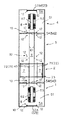
図2において、連接した4塔のうち、その一端部の第1の駐車塔1には、地上1階に自動車の入庫部5Aが設けられている。この入庫部5Aは、この立体駐車装置全体、すなわち4基の駐車塔1、2、3、4共通の入庫部であり、その正面側の壁面中央に入庫口52Aがエレベータ10への乗込方向に対向して形成されていて、入庫の自動車が前進入庫されるようになっている。さらにこの入庫部5Aと第2の駐車塔2との境界に設けられた間仕切り用の壁面中央に、入庫口52Aに対向して開口54が所定の大きさに形成されて、ここを通じて入庫の自動車が第2の駐車塔2、または第3の駐車塔3、または第4の駐車塔4へ移送されるようになっている。また、エレベータ10の着床位置の下方にはピット53が凹状に設けられていて、これが後述の第2の駐車塔2のフロアに連続的に形成されている。
【0021】
図2において、連接した4塔のうち、その他端部の第4の駐車塔4には、地上1階に自動車の出庫部5Bが設けられている。この出庫部5Bは、この立体駐車装置全体、すなわち4基の駐車塔1、2、3、4共通の出庫部であり、その背面側の壁面中央に出庫口52Bが形成されて、出庫部5Bに移送された入庫時の向きのままの出庫の自動車が前進出庫されるようになっている。さらにこの出庫部5Bと第3の駐車塔3との境界に設けられた間仕切り用の壁面中央に開口54が所定の大きさに形成されて、ここを通じて第1の駐車塔1、または第2の駐車塔2、または第3の駐車塔3から取り出された出庫の自動車が出庫部5Bへ移送されるようになっている。また、エレベータ10の着床位置の下方にはピット53が凹状に設けられていて、これが後述の第3の駐車塔3のフロアに連続的に形成されている。
【0022】
なお、入庫部5Aの入庫口52A、出庫部5Bの出庫口52Bにそれぞれ、上下開閉式、または左右開閉式の自動ドア52Dが設けられていて、この入庫部5Aと第2の駐車塔2との間の開口54、この出庫部5Bと第3の駐車塔3との間の開口54にそれぞれ、上下開閉式、または左右開閉式、または所謂観音開き式の自動ドア54Dが設けられている。立体駐車装置の動作中は、入庫口52A、出庫口52Bの自動ドア52Dは閉じられていて、開口54の自動ドア54Dは選択的に開閉される。また、自動車の入庫または出庫に際し、自動車や乗員が入庫部5Aに入室する場合、または出庫部5Bから退室する場合に、開口54の自動ドア54Dが閉じられて、入庫口52A、出庫口52Bの自動ドア52Dが開かれる。後述するこの立体駐車装置の入庫動作、出庫動作の説明では、これらの自動ドア52D、54Dの動作説明を省略してある。
【0023】
これら入庫部5A、出庫部5Bに隣接する第2、第3の駐車塔2、3の地上1階部分は、そのフロアレベルが自動車の入庫部5A、出庫部5Bの各ピット53の底面と同じかそれよりも低く設定されていて、その幅方向中央、すなわちエレベータ10のガイドレール12間に第1の駐車塔1のピット53を始端とし、第4の駐車塔4のピット53を終端とする搬送台車の往復移動路である搬送路6が設定され、そこに一対の走行レール61が敷設されている。そして、第2の駐車塔2の搬送路6の両側方に退避路7が設定され、図3に示すように、搬送路6の走行レール61の一部(退避路7の部分)が分断され、そこに(その分断部分に)2組の一対の可動レール71、72とそのスライド機構73が設けられている。各一対の可動レール71、72はそれぞれ、一対の走行レール61と同じ間隔で、平行であり、横方向に並列に組まれている。スライド機構73は、図4に示すように、各一対の可動レール71、72を並列配置により支持する支持フレーム74と、この支持フレーム74の両側に軸支された複数のローラ75と、走行レール61の下方でその直交方向に敷設されて、支持フレーム74を横行案内する一対の退避レール76と、支持フレーム74を進退駆動する支持フレーム駆動装置77とを備える。ここで、支持フレーム駆動装置77は、一対の退避レール76の両端側に軸支された2個一対のスプロケット78と、これらのスプロケット78に巻き掛けられ、一端が支持フレーム74の一方の側部に、他端が支持フレーム74の他方の側部に連結された一対の駆動チェーン79と、2つのスプロケット78の回転軸に作動連結され、これらを回転駆動する減速機付きの駆動モータ80とを備える。このようにして、各一対の可動レール71、72が一体となって一対の走行レール61に対して横断的に移動することにより、一方の一対の可動レール71(または72)を片側一方の退避路7に退避するとともに、他方の一対の可動レール72(または71)を片側他方の退避路7から一対の走行レール61に連続的に配置して走行レール61の一部を形成する。
【0024】
このように形成された搬送路6または退避路7上には、図2に示すように、2台の搬送台車8が配置されている。各搬送台車8は、図5に示すように、モータ駆動の自走式の台車81と、台車81上に搭載された自動車載置用のフォーク状の固定ステージ82とを備える。ここで、台車81は、両側前後に車輪84を軸支されたフレーム85と、前後車輪84の一方に作動連結された走行駆動モータ86とからなり、固定ステージ82は、エレベータ10の昇降ステージ13が通り抜け可能に中央の板状のフレーム89とその両側のフォーク部90とからなり、各フォーク部90に自動車の前後輪を支持して自動車を搬送移動する。
【0025】
次に、この立体駐車装置の入庫動作および出庫動作について説明する。自動車を入庫する場合、図2において、まず自動車が前進で入庫口52Aを通じて自動車の入庫部5Aに乗り入れられ、そのフロア51上に予め待機中のエレベータ10の昇降ステージ13に乗り込まれる。ここで乗員は自動車の入庫部5Aを退出する。
【0026】
この自動車を第1の駐車塔1の格納部20に格納する場合は、図1において、エレベータ10が上昇駆動され、自動車が昇降ステージ13に支持されて上方の格納部20へ移送される。昇降ステージ13は指定した駐車階層へ上昇されて、その階層の所定の高さ位置で停止されると、その階層の駐車区画21の横行台車22がその横行駆動装置24により一対の横行レール23上を、駐車区画21から昇降路11へ横行され、昇降路11上の昇降ステージ13の直下に進入される。次に、昇降ステージ13が下降され、その横行台車22を通り抜けると同時に自動車が昇降ステージ13から横行台車22へ受け渡しされる。続いて横行台車22はその駐車区画21に戻されて自動車が格納される。
【0027】
また、この自動車を第2の駐車塔2、または第3の駐車塔3、または第4の駐車塔4の格納部20に格納する場合は、図2において、自動車の入庫部5Aでまず、エレベータ10の下降駆動により、昇降ステージ13がピット53内に下げられ、自動車は予め自動車の入庫部5Aのピット53に待機中の搬送台車8の固定ステージ82へ受け渡しされる。続いて、搬送台車8に組み込まれた自走式の台車81の走行駆動モータ86の駆動により、その搬送台車8が自動車の入庫部5Aのピット53から搬送路6の走行レール61上を第2の駐車塔2、または第3の駐車塔3、または第4の駐車塔4へ移動され、自動車が搬送される。
【0028】
第2の駐車塔2、または第3の駐車塔3、または第4の駐車塔4への搬送途上、搬送路6の走行レール61上に移送途中の入庫または出庫の自動車を載せた搬送台車8がある場合、予め定められた所定の優先順位に従う。先行する搬送台車8を優先する場合は、その搬送台車8の動作が終わるまで、後行の搬送台車8は搬送路6上で待機される。なお、先行の搬送台車8の動作が終わると、その搬送台車8が退避路7へ退避されて、後行の搬送台車8が搬送路6を走行する。反対に後行の搬送台車8を優先する場合は、先行の搬送台車8が搬送路6から退避路7に退避され、後行の搬送台車8が搬送路6を通行する。
【0029】
搬送台車8の退避動作は次のように行われる。退避される一方の搬送台車8が走行レール61上に連続的に配置された一方の一対の可動レール71(または72)に移動停止され、ここで可動レール71、72のスライド機構73が駆動される。図3、図4に示すように、駆動モータ80の駆動により一対のスプロケット78が回転駆動されて、各駆動チェーン79が回転される。可動レール71、72の支持フレーム74が駆動チェーン79に引っ張られ、複数のローラ75の退避レール76上の移動により、搬送台車8を載せた一方の一対の可動レール71(または72)が片側一方の退避路7へ横行されて、その上の搬送台車8が退避路7へ退避される。同時に片側他方の退避路7から他方の可動レール72(または71)が走行レール61上に連続的に配置される。そして、通行を優先された他方の搬送台車8が走行レール61上を走行される。その通行後、再び各一対の可動レール71、72の横行により、退避路7へ退避された可動レール71(または72)が搬送路6の走行レール61の位置に戻されて、退避路7に横行退避された搬送台車8が搬送路6上に戻され、走行レール61上を走行される。
【0030】
続いて、図2において、入庫の自動車を載せた搬送台車8が第2の駐車塔2、または第3の駐車塔3、または第4の駐車塔4で停止されると、その下方に予めエレベータ10の昇降ステージ13が下降されていて、この昇降ステージ13の上昇により、自動車が搬送台車8の固定ステージ82から昇降ステージ13へ受け渡しされて、上方の格納部20へ移送される。格納部20への格納手順は第1の駐車塔1への格納の説明と同じである。
【0031】
反対に、第1、第2、第3の駐車塔1、2、3の格納部20から自動車を出庫する場合、図1において、まず、その格納部20からエレベータ10の昇降ステージ13へ自動車が載せ替えられる。すなわち、自動車が格納されている駐車区画21の横行台車22がその横行駆動機構24により横行レール23上を、駐車区画21から昇降路11まで横行される。この動作に同期して、エレベータ10の昇降駆動機構により昇降ステージ13が昇降路11上を上昇され、その横行台車22を通り抜けると同時に、自動車が横行台車22から昇降ステージ13へ受け渡しされる。続いて横行台車22がその駐車区画21へ戻されると、昇降ステージ13は地上1階の搬送路6まで下降される。図2において、搬送路6の走行レール61上には予め搬送台車8が待機されていて、昇降ステージ13が搬送台車8の固定ステージ82を通り抜けて停止される。この通り抜けにより自動車が昇降ステージ13から固定ステージ82へ受け渡しされる。
【0032】
ここで、搬送台車8が走行レール61上を第4の駐車塔4の自動車の出庫部5Bへ向けて移動され、自動車が搬送される。その搬送途上に、移送途中の入庫の自動車または出庫の自動車を載せた搬送台車8がある場合は、既に説明したとおり、予め定められた所定の優先順序に従い、必要がある場合は、いずれか一方の搬送台車8が搬送路6から退避路7に退避されて、いずれか他方の搬送台車8が搬送路6を通行する。その通行後、退避路7に退避された搬送台車8は搬送路6に戻されて、走行を続行する。
【0033】
搬送台車8が第4の駐車塔4の出庫部5Bまで移動されると、ここで、乗員が出庫部5Bに進入し、乗車する。自動車が前進で出庫口52Bを通じて出庫部5Bを退出する。
【0034】
また、第4の駐車塔4から自動車を出庫する場合は、図1において、第1の駐車塔1の出庫と同様に、エレベータ10の昇降ステージ13が格納部20へ上昇され、自動車が載せられて、地上1階の出庫部5Bまで下降される。図2において、ここで、乗員が自動車の出庫部5Bに進入し、乗車する。自動車が前進で出庫口52Bを通じて自動車の出庫部5Bを退出する。
【0035】
このように、上記第1の実施例によれば、4基のエレベータ式の駐車塔1、2、3、4を縦列に連続して設置したことにより自動車の収容台数の拡大を図ることができ、第1、第2、第3、第4の駐車塔1、2、3、4間に自動車の搬送路6を設け、そこに自走式の搬送台車8を往復走行させ、自動車を搬送台車8に載せて搬送するようにしているので、自動車を速い搬送速度で移送することができる。
【0036】
また、第1の駐車塔1に入庫部5Aを設け、第4の駐車塔4に出庫部5Bを設け、自動車の入庫から出庫まで、第1、第2、第3、第4の駐車塔1、2、3、4間の通り抜け方式により行うので、自動車を旋回することなしに、自動車を前進で入庫し、前進で出庫することができ、自動車の入出庫を円滑、かつ迅速に行うことができる。従来のように、自動車の旋回装置などが不要になるから、コストの低減を図ることもできる。
【0037】
搬送路6の一部、ここでは第2の駐車塔2に搬送台車8の退避路7を設け、搬送路6上に2台の搬送台車8を配置しているので、一方の搬送台車8で入庫または出庫の自動車を搬送するとともに、他方の搬送台車8で次の入庫準備または出庫準備を併せて行えるので、自動車の入出庫を円滑、かつ迅速に行うことができる。
【0038】
搬送台車8の退避路7に、一対の走行レール61を分断し、走行レール61に連続して配置可能に並列配置された2組の一対の可動レール71、72とそのスライド機構73とを設置しているので、簡単な構造で、搬送台車8の退避操作を確実に行うことができる。
【0039】
また、そのスライド機構73を、2組の一対の可動レール71、72を支持するローラ75付きの支持フレーム74と、支持フレーム74を横行案内する一対の退避レール76と、支持フレーム駆動装置77として、退避レール76の両端側に軸支されたスプロケット78と、これらのスプロケット78に巻き掛けられ、支持フレーム74に連結された駆動チェーン79と、スプロケット78を回転駆動する駆動モータ80とにより構成しているので、簡単な構造を実現して、コストの低減を図ることができる。
【0040】
(実施例2)
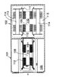
図6は本発明の第2の実施例の構成が示されている。この実施例と第1の実施例とは地上1階の退避路の数と搬送台車の台数が異なり、その他の箇所は共通になっている。
【0041】
図6において、第1、第4の駐車塔1、4の地上1階にそれぞれ、自動車の入庫部5A、出庫部5Bを備えていて、そのフロア51にピット53が設けられていることは既に説明したとおりである。
【0042】
両者のピット53とほぼ同じレベルに形成された第2、第3の駐車塔2、3のフロアにはそれぞれ、第1の駐車塔1のピット53を始端とし、第4の駐車塔4のピット53を終端とする自動車の搬送路6の両側方に自動車の退避路7が設定されている。すなわち、搬送路6の走行レール61が第2、第3の駐車塔2、3ごとに分断されていて、それぞれに一対の走行レール61の一部として連続して配置可能な横方向に並列配置の2組の一対の可動レール71、72とそのスライド機構73とを備えている。なお、これらの装置構成は、前述したとおりである。
【0043】
このように形成された搬送路6の走行レール61上または退避路7の可動レール71または72上には、全駐車塔1、2、3、4のうち搬送台車8がない駐車塔を1塔用意するため、合計3台の搬送台車8が任意の駐車塔に配置されている。なお、各搬送台車8の構造は、前述したとおりである。
【0044】
このような構成から、自動車を入庫する場合には、基本的に第1の実施例と同様な動作が行われ、さらに第2、第3の駐車塔2、3に備えた退避路7と合計3台の搬送台車8の選択的な利用により新たな動作が得られる。
【0045】
例えば、入庫、出庫が連続する場合、入庫の自動車が自動車の入庫部5Aに待機中の搬送台車8に載せられて搬送されるまでに、第2、第3、第4の駐車塔2、3、4では、各駐車塔2、3、4ごとに次の出庫準備が行われる。
【0046】
第2の駐車塔2、または第3の駐車塔3においては、格納部20から取り出された自動車が搬送台車8上に受け渡しされ、これが退避路7に待機される。このときエレベータ10の昇降ステージ13は最下降位置で停止、待機される。なお、この第2、第3の駐車塔2、3の出庫準備に併せて、第4の駐車塔4の出庫部5Bでは、そのピット53に出庫の自動車を載せた搬送台車8が入れるように、ピット53が開放される。つまり、ここでは予め第4の駐車塔4に搬送台車8がない状態になっている。
【0047】
また、第4の駐車塔4において、その格納部20から出庫の自動車が取り出され、出庫部5Bに移送された場合、この自動車は出庫部5Bから直接出庫される。
【0048】
このような出庫準備が併せて行われながら、自動車の入庫部5Aで入庫の自動車が搬送台車8上に載せられると、走行レール61上を第2の駐車塔2、または第3の駐車塔3、または第4の駐車塔4まで移動され、停止される。またここで、出庫の自動車を優先する場合には、入庫の自動車を載せた搬送台車8が第2の駐車塔2、または第3の駐車塔3で停止され、この駐車塔2または3で、可動レール71、72のスライド機構73が作動される。すなわち走行レール61に連続的に配置されている一方の可動レール71(または72)が片側一方の退避路7へ横行されて、入庫の自動車を載せた搬送台車8が片側一方の退避路7に横行退避される。同時に他方の可動レール72が片側他方の退避路7から横行されて、走行レール61上に連続的に配置され、出庫の自動車を載せた搬送台車8が走行レール61上に移動される。そして、この通行を優先された搬送台車8が走行レール61上を自動車の出庫部5Bまで走行され、そこで出庫される。その通行後、退避路7に横行退避された搬送台車8が再び各可動レール71、72の横行により搬送路6に戻される。そして、入庫の自動車を載せた搬送台車8の下方に予め待機されている昇降ステージ13が上昇され、自動車が搬送台車8の固定ステージ82から昇降ステージ13へ受け渡しされて、上方の格納部20へ移送される。
【0049】
また、入庫が連続する場合、先の入庫の自動車を載せた搬送台車8が駐車塔2、3、または4へ移動されると即座に、後の入庫の自動車を載せるための空の搬送台車8が送り出される。すなわち、自動車の入庫部5Aに待機中の搬送台車8に自動車が載せられて、走行レール61上を入庫先の駐車塔2、3、または4へ移動されると、入庫先が第2の駐車塔2または第3の駐車塔3の場合は、その搬送台車8が一旦搬送路6から退避路7へ退避され、空の搬送台車8が退避路7から搬送路6へ移動される。すなわち、第2の駐車塔2または第3の駐車塔3において、スライド機構73の作動により各一対の可動レール71、72が横行されて、入庫の自動車を載せた搬送台車8が片側一方の退避路7へ横行退避され、片側他方の退避路7に空の搬送台車8が停止されている場合はこれが搬送路6の走行レール61上に横行移動される。なお、その駐車塔に空の搬送台車8がない場合には、他の駐車塔でスライド機構73が作動されて、空の搬送台車8が搬送路6上に横行移動される。
【0050】
また、入庫先が第4の駐車塔4の場合は、入庫の自動車を載せた搬送台車8が第4の駐車塔4へ移動した後、第2の駐車塔2または第3の駐車塔3で同様にして、スライド機構73の作動により各一対の可動レール71、72が横行されて、空の搬送台車8が搬送路6へ上に横行移動される。
【0051】
このようにして空の搬送台車8が搬送路6上の通行を優先されて、走行レール61上を第1の駐車塔1の自動車の入庫部5Aまで移動され、次の入庫が行われる。さらに入庫が続く場合は、同様の動作が繰り返される。なお、このように入庫が連続的に行われている間に、先に入庫された自動車は搬送台車8からエレベータ10に受け渡しされて、格納部20へ格納される。
【0052】
また、出庫が連続する場合、所謂ピストン輸送式に出庫の自動車を載せた搬送台車8が繰り出される。すなわち、第1、第2、第3の駐車塔1、2、3の格納部20から出庫の自動車が取り出されると、各駐車塔1、2、3ごとに搬送台車8に受け渡しされる。そして、最優先された自動車を載せた搬送台車8が搬送路6上に残される。第2の駐車塔2または第3の駐車塔3が最優先された場合は、その搬送台車8が搬送路6上の残り、第3の駐車塔3または第2の駐車塔2の搬送台車8は一旦各退避路7に待機され、第1の駐車塔1の搬送台車8は入庫部5Aにそのまま待機される。第1の駐車塔1が最優先された場合は、その搬送台車8が入庫部5Aに待機され、第2、第3の駐車塔2、3の搬送台車8はその退避路7に退避され、待機される。
【0053】
このようにして、1番目の出庫の自動車を載せた搬送台車8が搬送路6上の通行を優先され、その走行レール61上を第4の駐車塔4の自動車の出庫部5Bまで走行され、そこで自動車が出庫される。1番目の搬送台車8が出庫を完了すると、第1、第2、または第3の駐車塔1、2、3に戻される。そして第2の駐車塔2、または第3の駐車塔3において、そのスライド機構73の作動により各一対の横行レール71、72が横行されて、2番目の出庫の自動車を載せた搬送台車8が搬送路6上の通行を優先され、その走行レール61上を第4の駐車塔4の自動車の出庫部5Bまで走行されて、そこで自動車が出庫される。同様にして最後に、3番目の出庫の自動車を載せた搬送台車8が搬送路6上の通行を優先され、その走行レール61上を第4の駐車塔4の自動車の出庫部5Bまで走行されて、そこで自動車が出庫される。
【0054】
このように、上記第2の実施例によれば、自動車の入出庫部5A、5Bを設けている第1、第4の駐車塔1、4を除き、他の2基の駐車塔2、3にそれぞれ、退避路7を備え、合計3台の搬送台車8を配置しているので、各駐車塔2、3、4から空の搬送台車8を自動車の入庫部5Aへ連続的に繰り出すことができ、また各駐車塔1、2、3ごとに格納部20から自動車を取り出し、搬送台車8に載せて、第1の駐車塔1の場合入庫部5Aに、第2、第3の駐車塔2、3の場合各退避路7に待機しておき、各駐車塔1、2、3から連続的に搬送台車8を繰り出すことができるなど、入庫部5Aで入庫動作中または出庫部5Bで出庫動作中に、他の駐車塔で次の入庫準備または次の出庫準備を効率的に行え、自動車の入出庫を一層円滑、かつ迅速に行うことができる。
【0055】
【発明の効果】
以上、各実施例から明らかなように、本発明においては、n基のエレベータ式の駐車塔を縦列に連続して設置し、その両端の駐車塔の一方に自動車の入庫部を設け、他方に自動車の出庫部を設けるとともに、これら入出庫部間の各駐車塔間に搬送台車の搬送路とその退避路とを形成し、この搬送路上にフォーク状の固定ステージを搭載した自走式の搬送台車を任意の台数だけ配置して、自動車の入庫から出庫までを搬送台車による各駐車塔間の通り抜け方式により行うので、自動車の収容台数の拡大を図るとともに、自動車の入出庫部とn基の各駐車塔との間の自動車の搬送速度を高め、自動車の入出庫を円滑、かつ迅速に行うことができる。
【図面の簡単な説明】
【図1】本発明の第1の実施例におけるフォーク式立体駐車装置の格納部の平面図
【図2】同立体駐車装置の自動車の入出庫部並びにn基の駐車塔間に形成された搬送台車の搬送路および退避路の平面図
【図3】同立体駐車装置のn基の駐車塔間に形成された搬送台車の搬送路および退避路の部分拡大平面図
【図4】同立体駐車装置のn基の駐車塔間に形成された搬送台車の搬送路および退避路の部分拡大正面図
【図5】同立体駐車装置に用いられる搬送台車の拡大側面図
【図6】本発明の第2の実施例におけるフォーク式立体駐車装置の自動車の入出庫部並びにn基の駐車塔間に形成された搬送台車の搬送路および退避路の平面図
【図7】(a)従来の縦列式立体駐車装置の側面断面図
(b)同立体駐車装置の正面断面図
【図8】
同立体駐車装置の地上1階部分の平面図
【図9】同立体駐車装置の地上1階部分の側面断面図
【符号の説明】
1 第1の駐車塔
2 第2の駐車塔
3 第3の駐車塔
4 第4の駐車塔
5A 入庫部
5B 出庫部
51 フロア
52A 入庫口
52B 出庫口
52D 自動ドア
53 ピット
54 開口
54D 自動ドア
6 搬送路
61 走行レール
7 退避路
71、72 可動レール
73 スライド機構
74 支持フレーム
75 ローラ
76 退避レール
77 支持フレーム駆動装置
78 スプロケット
79 駆動チェーン
80 駆動モータ
8 搬送台車
81 自走式の台車
82 固定ステージ
84 車輪
85 フレーム
86 走行駆動モータ
89 フレーム
90 フォーク部
10 フォーク式のエレベータ
11 エレベータの昇降路
12 ガイドレール
13 昇降ステージ
14 サイドフレーム
15 フォーク部
20 自動車の格納部
21 駐車区画
22 横行台車
23 横行レール
24 横行駆動装置
25 フレーム
26 フォーク部
27 車輪
28 カバーフレーム
29 ギヤードモータ
30 フリクションローラ[0001]
BACKGROUND OF THE INVENTION
TECHNICAL FIELD The present invention relates to a fork type multi-story parking apparatus that continuously installs n elevator type parking towers to increase the number of cars accommodated.
[0002]
[Prior art]
Conventionally, an example of this type of three-dimensional parking apparatus is disclosed in Japanese Patent Publication No. 7-81417. In the case of this three-dimensional parking apparatus, as shown in FIG. 7, first and
[0003]
The first floor portion of the
[0004]
Further, as shown in FIG. 9, the
[0005]
In the case of entering a car, in FIG. 7, first, the car is first moved forward into the
[0006]
Further, when the car is unloaded from the first and
[0007]
[Problems to be solved by the invention]
In this kind of three-dimensional parking apparatus, the number of vehicles can be increased by effectively utilizing the three-dimensional space and installing the first and second parking towers continuously in a column, compared with the case of one vehicle. Has expanded more than twice. Accordingly, by continuously installing n parking towers, the number of vehicles accommodated can be increased by n times or more. However, for example, when four parking towers are installed in tandem, the distance between the car entry part and each parking tower becomes longer, and in order to quickly enter and exit the car, Need to increase. A method of pulling the swivel plate together with a part of the lifting / lowering swivel device like a conventional transfer device cannot sufficiently cope with this speed. Thus, even if the number of automobiles accommodated is increased by continuously installing n parking towers, a quicker warehousing operation and a quicker evacuation operation of the automobile are required accordingly.
[0008]
The present invention solves such a conventional problem, and aims to increase the number of vehicles accommodated by installing n fork-type parking towers continuously in a row, and to store and remove a vehicle. An object of the present invention is to provide an excellent fork type multi-story parking apparatus that can smoothly and quickly carry in and out of a vehicle by increasing the transport speed of the vehicle between the vehicle and each parking tower.
[0009]
[Means for Solving the Problems]
In order to achieve the above object, n elevator-type parking towers are continuously installed in a column, one of the parking towers at both ends thereof is provided with a car storage part, and the other is provided with a car exit part, A transport path for the transport carriage and a retreat path are formed between the parking towers between the entry / exit sections, and an arbitrary number of self-propelled transport carriages equipped with fork-shaped fixed stages are arranged on the transport path. In this way, the vehicle travels back and forth.
[0010]
According to the present invention, it is possible to increase the number of cars accommodated and to increase the speed at which the automobile is transported between the entry / exit section of the automobile and each parking tower so that the entry / exit of the automobile can be performed smoothly and quickly. Fork type multi-story parking device is obtained.
[0011]
DETAILED DESCRIPTION OF THE INVENTION
The fork type multi-story parking apparatus according to
[0013]
Claims of the
[0014]
Claims of the
[0015]
From each of the above configurations, when entering a car, the car is first moved forward into the car storage part, and between the car storage part and each parking tower, the car is placed on a self-propelled carriage. It is transferred by traveling on the conveyance path. If there is a transport cart with a car in transit or a car exiting in the middle of the transport, one of the transport carts is removed from the transport path when necessary according to a predetermined priority order. Retracted to the retreat path, one of the other transport carts passes through the transport path. After the passage, the transport carriage evacuated to the retreat path is returned to the transport path. In each parking tower, the automobile is transferred from the transporting carriage to the elevator lifting stage, transferred to the parking section by the lifting and lowering, and transferred to the transverse carriage in the parking section and stored.
[0016]
When leaving the car, in each parking tower, the car is transferred from the traversed carriage in the parking section to the elevator lift stage and is transferred to the transport path of the transport carriage by the lift. Subsequently, the automobile is transferred from the lifting stage to the transport carriage, and is transferred to the car unloading section by traveling on the transport path of the transport carriage. If there is a transport cart with a car in transit or a car exiting in the middle of the transport, one of the transport carts is removed from the transport path when necessary according to a predetermined priority order. Retracted to the retreat path, one of the other transport carts passes through the transport path. After the passage, the transport carriage evacuated to the retreat path is returned to the transport path. The car that has been transferred to the car unloading section by the transport cart is left as it is.
[0017]
Embodiments of the present invention will be described below with reference to FIGS. In each of the first and second embodiments, n = 4 fork type multi-story parking apparatus in which four elevator type parking towers are installed in tandem is illustrated as n = 4.
(Example 1)
1 and 2 show the overall configuration of the first embodiment of the present invention. In FIG. 1, 1 is a first parking tower, 2 is a second parking tower, 3 is a third parking tower, and 4 is a fourth parking tower, which are continuous in front and rear columns. Installed. The first, second, third, and fourth parking towers 1, 2, 3, and 4 are provided with a fork-
[0018]
Each
[0019]
The
[0020]
In FIG. 2, among the four connected towers, the
[0021]
In FIG. 2, among the four connected towers, the
[0022]
In addition, a vertical opening / closing type or a left / right opening / closing type
[0023]
The ground level of the second and
[0024]
On the
[0025]
Next, the warehousing operation and the warehousing operation of this multilevel parking device will be described. In the case of entering a car, in FIG. 2, the car is first moved forward to enter the car storage part 5 </ b> A through the entrance 52 </ b> A, and is placed on the
[0026]
When the automobile is stored in the
[0027]
Further, when the car is stored in the
[0028]
On the way to the
[0029]
The retracting operation of the
[0030]
Subsequently, in FIG. 2, when the
[0031]
On the other hand, when a car is delivered from the
[0032]
Here, the
[0033]
When the
[0034]
Further, when the car is to be delivered from the
[0035]
Thus, according to the first embodiment, it is possible to increase the number of cars accommodated by installing four elevator-
[0036]
In addition, the
[0037]
A part of the
[0038]
A pair of traveling
[0039]
Further, the
[0040]
(Example 2)
FIG. 6 shows the configuration of the second embodiment of the present invention. This embodiment is different from the first embodiment in the number of retreat paths on the first floor and the number of transport carts, and the other portions are common.
[0041]
In FIG. 6, the first and fourth parking towers 1, 4 have a car storage part 5 </ b> A and a car exit part 5 </ b> B on the first floor, respectively, and the
[0042]
On the floors of the second and
[0043]
On the traveling
[0044]
From such a configuration, when an automobile is received, basically the same operation as that of the first embodiment is performed, and the
[0045]
For example, when warehousing and unloading are continued, the second, third, and fourth parking towers 2, 3, until the warehousing vehicle is placed on the
[0046]
In the
[0047]
Moreover, in the
[0048]
When such a preparation for unloading is performed together and the arriving automobile is placed on the
[0049]
In addition, when the warehousing continues, when the
[0050]
In addition, when the warehousing destination is the
[0051]
In this way, the
[0052]
In addition, when the warehousing continues, the
[0053]
In this way, the
[0054]
Thus, according to the said 2nd Example, except the 1st,
[0055]
【The invention's effect】
As described above, as is clear from each embodiment, in the present invention, n elevator parking towers are continuously installed in a column, and a car storage part is provided on one of the parking towers at both ends, and the other is provided on the other. A self-propelled transport that has a car exit section and a transport path for the transport carriage and a retreat path between the parking towers between the entrance and exit sections, and a fork-shaped fixed stage is mounted on the transport path. Arbitrary number of trolleys are arranged, and from entry to delivery of vehicles by the passing method between parking towers by transport carts, the number of vehicles can be increased, and the number of vehicles in and out The conveyance speed of the automobile between each parking tower can be increased, and the entry / exit of the automobile can be performed smoothly and quickly.
[Brief description of the drawings]
FIG. 1 is a plan view of a storage portion of a fork type multilevel parking device according to a first embodiment of the present invention.
FIG. 2 is a plan view of a transport path and a retreat path of a transport carriage formed between a car entrance / exit section of the multi-story parking apparatus and n parking towers.
FIG. 3 is a partially enlarged plan view of a transport path and a retreat path of a transport carriage formed between n parking towers of the multilevel parking apparatus.
FIG. 4 is a partially enlarged front view of a transport path and a retreat path of a transport carriage formed between n parking towers of the multilevel parking apparatus.
FIG. 5 is an enlarged side view of a transport carriage used in the multilevel parking apparatus.
FIG. 6 is a plan view of a transport path and a retreat path of a transport carriage formed between a car entrance / exit portion and n parking towers of a fork type multilevel parking apparatus according to a second embodiment of the present invention.
7A is a side sectional view of a conventional multi-story parking apparatus.
(B) Front sectional view of the multi-story parking apparatus
[Fig. 8]
Plan view of the first floor of the multilevel parking device
FIG. 9 is a side sectional view of the first floor portion of the multilevel parking device.
[Explanation of symbols]
1 First parking tower
2 Second parking tower
3 Third parking tower
4th parking tower
5A warehousing part
5B shipping department
51 floors
52A Warehouse entrance
52B Exit
52D automatic door
53 pits
54 opening
54D Automatic door
6 Transport path
61 Traveling rail
7 Retreat path
71, 72 Movable rail
73 Slide mechanism
74 Support frame
75 Laura
76 Retraction rail
77 Support frame drive
78 Sprocket
79 Drive chain
80 Drive motor
8 Transport cart
81 Self-propelled cart
82 fixed stage
84 wheels
85 frames
86 Traveling drive motor
89 frames
90 Fork
10 Fork-type elevator
11 Elevator hoistway
12 Guide rail
13 Lifting stage
14 Side frame
15 Fork
20 Car storage
21 Parking lot
22 Traversing cart
23 Traverse Rail
24 Traverse drive device
25 frames
26 Fork
27 wheels
28 Cover frame
29 Geared motor
30 Friction roller
Claims (3)
前記連接した駐車塔のうち、一端部の駐車塔に自動車の入庫部を有するとともに他端部の駐車塔に出庫部を有し、
前記入庫部及び出庫部を有する駐車塔を含む前記各駐車塔間に一対の走行レールが敷設されて、自動車を前記エレベータとの間で受け渡し可能なフォーク状の固定ステージを有する複数の自走式の搬送台車が往復移動し、自動車を前記入庫部を有する駐車塔から前記出庫部を有する駐車塔までの各駐車塔間を搬送する搬送路と、
前記入庫部及び出庫部を有する駐車塔以外の任意の駐車塔に形成され、前記各搬送台車が前記搬送路から退避可能な退避路とを備え、
前記退避路は前記搬送路の走行レールが分断されて、その分断部に前記走行レールを直交方向に横断して、前記走行レールと平行な2組の一対の可動レールが移動可能に配置され、前記2組の一対の可動レールの一方が前記走行レールから退避されると、他方が前記走行レールに連続的に配置されて前記走行レールの一部を形成することを特徴とするフォーク式立体駐車装置。An elevator that lifts and lowers an automobile on a fork-shaped lifting stage, a plurality of parking sections formed in a hierarchy along the hoistway, a fork-shaped traversing carriage arranged in each parking section, and their traversal Fork type multi-story parking device comprising a traverse drive device traversing a carriage, and a plurality of parking towers of a type in which a vehicle is passed between an elevator and a traverse carriage,
Among the connected parking towers, the parking tower at one end has a warehousing part of the car and the parking tower at the other end has a delivery part,
A plurality of self-propelled types having a fork-like fixed stage in which a pair of traveling rails are laid between the parking towers including the parking tower having the warehousing part and the warehousing part, and capable of delivering the automobile to and from the elevator A transport path for reciprocating the carriage, and transporting the automobile between the parking towers from the parking tower having the warehousing part to the parking tower having the leaving part,
Formed in an arbitrary parking tower other than the parking tower having the warehousing part and the warehousing part, and each trolley includes a retreat path that can be retreated from the transportation path ,
In the retreat path, the traveling rail of the conveyance path is divided, and the pair of movable rails parallel to the traveling rail are movably arranged at the divided portion, crossing the traveling rail in the orthogonal direction, Fork type multi-story parking, wherein when one of the two pairs of movable rails is retracted from the traveling rail, the other is continuously disposed on the traveling rail to form a part of the traveling rail. apparatus.
Priority Applications (1)
| Application Number | Priority Date | Filing Date | Title |
|---|---|---|---|
| JP32389998A JP3638221B2 (en) | 1998-11-13 | 1998-11-13 | Fork type parking system |
Applications Claiming Priority (1)
| Application Number | Priority Date | Filing Date | Title |
|---|---|---|---|
| JP32389998A JP3638221B2 (en) | 1998-11-13 | 1998-11-13 | Fork type parking system |
Publications (2)
| Publication Number | Publication Date |
|---|---|
| JP2000145189A JP2000145189A (en) | 2000-05-26 |
| JP3638221B2 true JP3638221B2 (en) | 2005-04-13 |
Family
ID=18159864
Family Applications (1)
| Application Number | Title | Priority Date | Filing Date |
|---|---|---|---|
| JP32389998A Expired - Fee Related JP3638221B2 (en) | 1998-11-13 | 1998-11-13 | Fork type parking system |
Country Status (1)
| Country | Link |
|---|---|
| JP (1) | JP3638221B2 (en) |
Families Citing this family (1)
| Publication number | Priority date | Publication date | Assignee | Title |
|---|---|---|---|---|
| JP7097751B2 (en) * | 2018-06-08 | 2022-07-08 | Ihi運搬機械株式会社 | Parallel fork parking device and its driving method |
-
1998
- 1998-11-13 JP JP32389998A patent/JP3638221B2/en not_active Expired - Fee Related
Also Published As
| Publication number | Publication date |
|---|---|
| JP2000145189A (en) | 2000-05-26 |
Similar Documents
| Publication | Publication Date | Title |
|---|---|---|
| JP3529280B2 (en) | Fork-type multi-story parking facilities | |
| JP3357771B2 (en) | Underground multi-story parking device | |
| JP3638221B2 (en) | Fork type parking system | |
| JP3398076B2 (en) | Fork type multi-story parking device | |
| JP2863705B2 (en) | Mechanical multi-story parking device | |
| JP3056139B2 (en) | Mechanical parking lot | |
| JP4065633B2 (en) | Mechanical parking equipment | |
| JP4065631B2 (en) | Plane reciprocating parking system | |
| JP3657829B2 (en) | Plane reciprocating parking device and method for loading and unloading the same | |
| JP2745283B2 (en) | Elevator type multi-story parking device | |
| JP2662816B2 (en) | Underground multi-story parking system | |
| JP3295066B2 (en) | Multi-stage multilevel parking device | |
| JP3208554B2 (en) | Simultaneous multi-story parking system | |
| JP3448037B2 (en) | Plane reciprocating parking system | |
| JP2880115B2 (en) | Mechanical parking lot | |
| JP2001065185A (en) | Mechanical parking equipment | |
| JP2662819B2 (en) | Parking device with a mobile passage for the traveling trolley | |
| JP3936793B2 (en) | Mechanical parking equipment | |
| JP4335792B2 (en) | Mechanical parking device | |
| JP3942083B2 (en) | Elevator parking system with tandem berth and its entry / exit method | |
| JP2990050B2 (en) | Parking device with a vehicle carrier | |
| JP4369823B2 (en) | Elevator parking system | |
| JP3996023B2 (en) | Horizontal circulation parking system | |
| JP2837591B2 (en) | Large capacity parking lot | |
| JP2578023B2 (en) | Flat-bed reciprocating parking device for transfer and delivery of slat conveyor |
Legal Events
| Date | Code | Title | Description |
|---|---|---|---|
| A977 | Report on retrieval |
Free format text: JAPANESE INTERMEDIATE CODE: A971007 Effective date: 20040430 |
|
| A131 | Notification of reasons for refusal |
Free format text: JAPANESE INTERMEDIATE CODE: A131 Effective date: 20040525 |
|
| A521 | Written amendment |
Free format text: JAPANESE INTERMEDIATE CODE: A523 Effective date: 20040721 |
|
| A131 | Notification of reasons for refusal |
Free format text: JAPANESE INTERMEDIATE CODE: A131 Effective date: 20041005 |
|
| A521 | Written amendment |
Free format text: JAPANESE INTERMEDIATE CODE: A523 Effective date: 20041108 |
|
| TRDD | Decision of grant or rejection written | ||
| A01 | Written decision to grant a patent or to grant a registration (utility model) |
Free format text: JAPANESE INTERMEDIATE CODE: A01 Effective date: 20050105 |
|
| A61 | First payment of annual fees (during grant procedure) |
Free format text: JAPANESE INTERMEDIATE CODE: A61 Effective date: 20050107 |
|
| R150 | Certificate of patent or registration of utility model |
Free format text: JAPANESE INTERMEDIATE CODE: R150 |
|
| FPAY | Renewal fee payment (event date is renewal date of database) |
Free format text: PAYMENT UNTIL: 20080121 Year of fee payment: 3 |
|
| FPAY | Renewal fee payment (event date is renewal date of database) |
Free format text: PAYMENT UNTIL: 20090121 Year of fee payment: 4 |
|
| FPAY | Renewal fee payment (event date is renewal date of database) |
Free format text: PAYMENT UNTIL: 20100121 Year of fee payment: 5 |
|
| FPAY | Renewal fee payment (event date is renewal date of database) |
Free format text: PAYMENT UNTIL: 20110121 Year of fee payment: 6 |
|
| FPAY | Renewal fee payment (event date is renewal date of database) |
Free format text: PAYMENT UNTIL: 20110121 Year of fee payment: 6 |
|
| FPAY | Renewal fee payment (event date is renewal date of database) |
Free format text: PAYMENT UNTIL: 20120121 Year of fee payment: 7 |
|
| LAPS | Cancellation because of no payment of annual fees |