JP3636628B2 - Ground improvement method - Google Patents
Ground improvement method Download PDFInfo
- Publication number
- JP3636628B2 JP3636628B2 JP2000007982A JP2000007982A JP3636628B2 JP 3636628 B2 JP3636628 B2 JP 3636628B2 JP 2000007982 A JP2000007982 A JP 2000007982A JP 2000007982 A JP2000007982 A JP 2000007982A JP 3636628 B2 JP3636628 B2 JP 3636628B2
- Authority
- JP
- Japan
- Prior art keywords
- ground
- air
- ground improvement
- rotating shaft
- main body
- Prior art date
- Legal status (The legal status is an assumption and is not a legal conclusion. Google has not performed a legal analysis and makes no representation as to the accuracy of the status listed.)
- Expired - Fee Related
Links
Images


Description
【0001】
【発明の属する技術分野】
本発明は、地盤中に粉粒体の地盤改良材を供給して、原位置土と強制的に攪拌混合し、土と地盤改良材とを反応させて土質性状を安定化し、且つ強度を高める地盤改良工法に関するものである。
【0002】
【従来の技術】
従来、この種の地盤改良工法における空気抜きは、回転軸を角形にしたり、回転軸にフィンを設けて、回転軸外周と地盤とに隙間を形成し、この隙間を利用して用済みの空気を地上に導き、回転軸に嵌挿し地盤上に設置したフード内に回収するようにしている(特開昭57−61108号公報参照)。しかし、この従来例では回転軸が長尺の場合に隙間を維持するのが困難であり、また地盤の種類により空気の抜け具合が異なり、安定した地盤改良の施工が難しく、場合により地盤中に空気が残留するおそれがある。
【0003】
このような状況から、確実な空気抜きを行うことのできる工法として、(1) 地盤改良材と空気の混合流体を、上面は閉じられ底面のみ開いた中空体の攪拌翼内に吐出させ、地盤改良材は攪拌翼内の原位置土に付着させ、空気は回転軸の内部を通し地上で回収するようにした地盤改良工法が開示されている(特公昭61−16808号公報参照)。また、(2) 攪拌翼より僅かに上方の回転軸に、内部空間が回転軸内の空気回収路に連通している空気回収フードを装着し、この空気回収フードの下方開口に回転軸の昇降に応じて自動的に開閉する蓋を設けた地盤改良装置が開示されている(特公平5−8295号公報参照)。更に、(3) 地盤改良材を空気で圧送し、水底の地盤中に噴出させ、原位置土と攪拌混合する一方、用済みの空気を水底に設置したフードを経て大気中に放出し、その際フード内に水圧に相当する空気圧をかける水底地盤改良工法が開示されている(特公昭62
−49409号公報参照)。
【0004】
【発明が解決しようとする課題】
上記した公報例の空気抜きを行うことのできる地盤改良工法等は、いずれも空気の抜け道が作られ、用済みの空気はその抜け道から地上で回収され、誠に都合がよい。しかしながら、従来の工法により形成された空気の抜け道では、用済み空気の抜けは必ずしも十分ではなかった。すなわち、(1) の公報例では、何らかの事情で中空体の攪拌翼外に出た空気や更に攪拌翼上面に回り込んだ空気は回収し難く、(2) 及び(3) の公報例でも空気回収フードから外れた空気は回収し難く、回収されない空気による他の構造物の変位や地盤改良材の吐出抑制などの弊害が生ずるという問題があった。
【0005】
また、従来の工法で使用される施工装置は、攪拌翼を複雑な形状に加工したり、空気回収フードを設置したりする必要があり、装置の製造コストを上昇させると共に、該施工装置は使用し難い構造であり、作業者にとっては面倒な工程を含むものであった。
【0006】
従って、本発明の目的は、簡単な構造で、一対の回転軸間に空気の抜け道を形成して用済み空気を地上に排出し、他の構造物の変位や地盤改良材の吐出抑制などの弊害を防止できる地盤改良工法を提供することにある。
【0007】
【課題を解決するための手段】
かかる実情において、本発明者らは、上記目的を達成するため鋭意検討を行った結果、一対の回転軸間で、攪拌翼の上方に差し渡しで設置される振れ止め板の厚みを回転軸の軸径と同等以上にすれば、回転軸の貫入時及び引き抜き時に回転軸間内に存在する原位置土の一部を十分にほぐすことができ、このほぐされた原位置土内の空隙が空気の抜け道となり、用済み空気は該空気の抜け道を通って、地上に排出されることなどを見出し、本発明を完成するに至った。
【0008】
すなわち、本発明は、一対の回転軸の下部に放射状に設けた1以上の攪拌翼の回転域の地盤中に、空気と共に粉粒体の地盤改良材を吐出させ、原位置土と攪拌混合し、空気は地上にて回収してなる地盤改良工法において、前記一対の回転軸間には、前記攪拌翼より上方の位置に前記回転軸に遊嵌する軸受け部と、前記軸受け部を連接する本体部からなる振れ止め板を差し渡しで設け、前記振れ止め板の本体部は厚みが回転軸の径と同等以上とし、且つ平面視で開口構造を除くものであって、前記空気を前記振れ止め板でほぐされた地盤を通って上方に排出し、地上にて回収することを特徴とする地盤改良工法を提供するものである。かかる構成を採ることにより、一対の回転軸間で、且つ攪拌翼の上方側に存在する原位置土は回転軸の引き抜き時に、所定の厚みを有する振れ止め板の上方移動に伴うほぐし効果により十分にほぐされ、このほぐされた原位置土内の空隙が空気の抜け道となり、用済み空気は該空気の抜け道を通って、地上に排出される。
【0009】
【発明の実施の形態】
以下、本発明の実施の形態における地盤改良工法を図1〜図6に基づいて説明する。図1は本発明の実施の形態である地盤改良工法で使用する施工装置の模式図、図2は図1のA−A線に沿った断面図、図3はB−B線に沿った断面図、図4は回転軸の横断面図、図5は本発明の実施の形態の地盤改良工法の工程を説明する模式図、図6は図5(C)のC−C線に沿って見た図である。本発明の地盤改良工法は、施工装置10の一対の回転軸1、1の下方部に放射状に設けた1以上の攪拌翼2の回転域の地盤中に、空気と共に粉粒体の地盤改良材を地盤改良材吐出口4から吐出させ、原位置土と攪拌混合し、空気は地上にて回収してなるものである。
【0010】
施工装置10において、一対の回転軸1、1間で、且つ攪拌翼2より上方の位置には振れ止め板5が差し渡しで設けられている。振れ止め板5は回転軸1に遊嵌する軸受け部52、52と、軸受け部52を連接する本体部51とからなる。図2及び図3に示すように、本体部51は断面が菱形状の中空管からなり、本体部51の厚み寸法Wは回転軸1の径Dより大きい。この本体部51の形状は、本体部51の厚み寸法Wが回転軸1の径Dと同等以上であれば、特に制限されず、例えば断面が円形状、四角状、逆三角状、Y字状のものも使用できる。本体部51の厚み寸法Wの最大値は、土質や施工装置の大きさ等を考慮し、回転軸の上昇に障害を与えない範囲で適宜に決定される。また、本体部51は従来の施工装置の振れ止め板の形状である断面がI字状の平板に、例えば断面が三角形の帯状突状物などを接合して、本体部51の厚み寸法Wを大きくなるように調整したものでもよい。本体部51の厚み寸法Wは本体部51の全長に亘り形成するのが好ましいが、用済み空気を排出できる程度に土がほぐれるのであれば、本体部の全長の一部であってもよい。図1において、符号6は共回り防止板であり、回転軸1の共回り防止板6の上下に位置する攪拌翼2、2の共回りを防止するために設置される。
【0011】
回転軸1は、施工設備の回転駆動機7に昇降自在、且つ回転自在に吊り下げられ、角パイプ状をなし、図4に示すようにその内部の中空部には地盤改良材や吐出空気が流通する通路15が通されている。回転軸1の下部には複数の攪拌翼2a、2bが設けられ、それらの1の攪拌翼2aにおける回転方向裏側のつけ根部分の回転軸1の外周に地盤改良材吐出口4が設けられている。また、回転軸の下方に位置する他の攪拌翼2bにおける回転方向裏側のつけ根部分の回転軸1の外周に空気吐出口3が設けられている。空気吐出口3及び地盤改良材吐出口4はいずれも通路15に接続し、この通路15は地上13の圧縮空気の吐出空気供給設備や地盤改良材供給設備(不図示)に接続している。回転軸1は角パイプ状以外に、例えば、丸パイプ状であってもよい。尚、空気吐出口3は地盤改良材吐出口
として使用してもよい。
【0012】
次に、本発明の実施の形態における地盤改良工法を図5を参照して説明する。図5は模式図であり、攪拌翼は説明の便宜上回転軸1個当たり1段とする例で説明する。回転駆動機7により回転軸1を正転方向に回転させながら地盤9に貫入させる際、地上13の吐出空気供給設備から、例えば3〜10kg/cm2 の圧縮空気を図5では省略する空気吐出口3から吐出させ、回転軸1の外周回りの地盤を予めほぐしておく(図3(A))。所定の深度まで到達すると、空気吐出口3からの空気の吐出を停止し、回転軸貫入工程は終了する(図3(B))。次に、回転軸1を逆転方向に回転させながら地盤から引き抜く際、地上13の地盤改良材供給設備から空気輸送された地盤改良材を地盤改良材吐出口4から吐出し、地盤中に攪拌混合させて改良柱体12を形成する。その際振れ止め板5は回転軸の上昇と同様に地盤中を上昇することから、振れ止め板本体部51の幅広効果により、図6中の攪拌翼2の上方位置側の2点鎖線で囲まれる部分(斜線部)にほぐされた原位置土を形成させることができる。このため、用済みの空気は、このほぐされた原位置土内の隙間を通って、図5中(C)の矢印の示す方向に排出され、地上13にて回収される。なお、回転軸1を地盤に貫入させる際、あるいは貫入及び引き抜き双方の際、地盤改良材吐出口4から地盤改良材を吐出させ、地盤中で攪拌混合させてもよい。なお、引き抜き時の回転軸の回転は逆転方向に限定されず、正転方向であってもよい。
【0013】
本実施の形態例によれば、一対の回転軸間に存在する原位置土は回転軸の引き抜き時に、所定の厚みを有する振れ止め板の上方移動に伴うほぐし効果により十分にほぐされ、このほぐされた原位置土内の空隙が空気の抜け道となり、用済み空気は該空気の抜け道を通って、地上に排出される。
【0014】
以上、本発明の実施形態を説明したが、具体的な構成はこれに限定されず、本発明の趣旨を逸脱しない範囲内での変更、追加は本発明の範囲内である。
【0015】
【実施例】
次に、実施例を挙げて、本発明を更に具体的に説明する。
実施例1
X市Y線で本発明の地盤改良工法を行った。使用した施工装置は図1〜図4に示すものと同様のものである。改良深度は30mであり、一個の改良柱体を造成する時間を求めた。結果を図7に示す。図7は、縦軸は深度、横軸は施工時間であり、回転軸の先端部の軌跡を描いたものである。a点から貫入を開始して所定の深度30mに達した点bにおいて、地盤改良材吐出口が目詰まりし地盤改良材が吐出不良となった。この詰まりを解消するため、地盤改良材吐出口4から圧縮空気を吐出しながら回転軸を上方へ引き上げたところ、所定深度30mから10m上方の地点cで詰まり物を除去できた。再度の貫入後、所定深度のd地点まで到達し、以後引き抜き工程を行い、e点において、回転軸を地上に引き抜き改良柱体を造成できた。a〜eまでの所要時間は1.5時間程度であった。
【0016】
比較例1
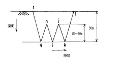
振れ止め板を断面がI字状のものを使用した以外は、実施例1と同様の方法で行った。この場合、振れ止め板の本体部の厚みは、回転軸の径より小さいものであった。結果を図8に示す。図8は図7と同様で回転軸の先端の軌跡を示すものである。比較例1においては、最初の目詰まりを解消するのに回転軸を所定深度から15〜20m引き上げる必要があった(図中、h点)。更に、目詰まりはi点で生じたため、同様の目詰まり物除去工程を行った(図中、i点からj点)。このため、開始地点aから改良柱体の造成を完了する地点lまでの所要時間は3〜4時間であった。
【0017】
実施例1及び比較例1から、本発明の工法によれば、従来の工法に比して、工期が1/2に短縮できることが判明した。
【0018】
【発明の効果】
本発明によれば、一対の回転軸間に存在する原位置土は回転軸の引き抜き時に、所定の厚みを有する振れ止め板の上方移動に伴うほぐし効果により十分にほぐされ、このほぐされた原位置土内の空隙が空気の抜け道となり、用済み空気は該空気の抜け道を通って、地上に排出することができ、他の構造物の変位や地盤改良材の吐出抑制などの弊害を防止できる。このように、振れ止め板の本体部の幅寸法を広く変更するだけで、工期は従来の半分に短縮できる。
【図面の簡単な説明】
【図1】 本発明の実施の形態である地盤改良工法で使用する施工装置の模式図である。
【図2】 図1のA−A線に沿って見た端面図である。
【図3】 図1のB−B線に沿って見た図である。
【図4】 回転軸の横断面図である。
【図5】 本発明の実施の形態の地盤改良工法の工程を説明する模式図である。
【図6】 図5(C)のC−C線に沿って見た図である。
【図7】 実施例1の工法における回転軸先端の軌跡を示す図である。
【図8】 比較例1の工法における回転軸先端の軌跡を示す図である。
【符号の説明】
1 回転軸
2、2a、2b 攪拌翼
3 空気吐出口(地盤改良材吐出口)
4 地盤改良材吐出口
5 振れ止め板
6 共回り防止板
7 回転駆動機
9 地盤
10 施工装置
11 原位置土
12 改良柱体
13 地上
15 地盤改良材や吐出空気の通路
16 振れ止め板の上方移動によりほぐされた土
51 振れ止め板の本体部
52 軸受部
W 振れ止め板の本体部の厚み
D 回転軸の径[0001]
BACKGROUND OF THE INVENTION
The present invention supplies powder ground improvement material into the ground, forcibly mixes with the soil in situ, reacts the soil with the ground improvement material, stabilizes the soil properties, and increases the strength. It relates to the ground improvement method.
[0002]
[Prior art]
Conventionally, in this kind of ground improvement method, the air is removed by making the rotary shaft square or by providing fins on the rotary shaft to form a gap between the outer periphery of the rotary shaft and the ground. They are guided to the ground and inserted into a rotating shaft so as to be collected in a hood installed on the ground (see JP-A-57-61108). However, in this conventional example, it is difficult to maintain a gap when the rotating shaft is long, and the degree of air removal varies depending on the type of ground, making it difficult to perform stable ground improvement. Air may remain.
[0003]
Under such circumstances, as a construction method that can perform reliable air venting, (1) The ground improvement material and the mixed fluid of air are discharged into the stirring blades of the hollow body whose top surface is closed and only the bottom surface is open, and the ground improvement There has been disclosed a ground improvement method in which the material is attached to the in-situ soil in the stirring blade and the air is collected on the ground through the inside of the rotating shaft (see Japanese Patent Publication No. 61-16808). (2) An air recovery hood whose inner space is in communication with the air recovery path in the rotation shaft is mounted on the rotation shaft slightly above the stirring blade, and the rotation shaft is lifted and lowered at the lower opening of the air recovery hood. A ground improvement device provided with a lid that automatically opens and closes in response to the above has been disclosed (see Japanese Patent Publication No. 5-8295). In addition, (3) ground improvement material is pumped with air, spouted into the ground at the bottom of the water, and stirred and mixed with the soil in situ, while used air is released into the atmosphere through a hood installed at the bottom of the water, An underwater ground improvement method for applying an air pressure equivalent to the water pressure in the hood is disclosed (Japanese Patent Publication No. 62).
-49409).
[0004]
[Problems to be solved by the invention]
All of the ground improvement methods and the like that can perform air venting in the above-mentioned publications are very convenient because an air passage is created and used air is collected on the ground from the passage. However, in the air passage formed by the conventional construction method, the removal of used air is not always sufficient. That is, in the publication example of (1), the air that has come out of the stirring blade of the hollow body for some reason or the air that has further circulated to the upper surface of the stirring blade is difficult to recover. In the publication examples of (2) and (3), There is a problem that the air that has been removed from the recovery hood is difficult to recover, and adverse effects such as displacement of other structures due to the unrecovered air and suppression of discharge of the ground improvement material occur.
[0005]
In addition, the construction equipment used in the conventional construction method needs to process the stirring blade into a complex shape or install an air recovery hood, which increases the manufacturing cost of the equipment and uses the construction equipment. The structure is difficult to perform, and includes troublesome processes for the operator.
[0006]
Accordingly, an object of the present invention is to provide a simple structure, form an air passage between a pair of rotating shafts and discharge used air to the ground, and to prevent displacement of other structures and discharge of ground improvement materials. It is to provide a ground improvement method that can prevent harmful effects.
[0007]
[Means for Solving the Problems]
In such a situation, the present inventors have intensively studied to achieve the above object, and as a result, the thickness of the steady rest plate installed over the stirring blade between the pair of rotating shafts is set to the axis of the rotating shaft. If the diameter is equal to or greater than the diameter, a part of the in-situ soil existing between the rotating shafts can be sufficiently loosened when the rotating shafts are inserted and withdrawn. It became an escape route, and it was found that used air was discharged to the ground through the escape route of the air, and the present invention was completed.
[0008]
That is, in the present invention, the ground improvement material of the granular material is discharged together with air into the ground in the rotation region of one or more stirring blades provided radially below the pair of rotating shafts, and is stirred and mixed with the in-situ soil. In the ground improvement method in which air is collected on the ground, between the pair of rotating shafts, a bearing portion that is loosely fitted to the rotating shaft at a position above the stirring blade, and a main body that connects the bearing portions vibration provided a stop plate in the across consisting section, the body portion of the bracing plate and a thickness equal to or more than the diameter of the rotating shaft, and be one except the open structure in plan view, the bracing plate the air The ground improvement construction method is characterized in that it is discharged upward through the ground loosened in the step and collected on the ground. By adopting such a configuration, the in-situ soil existing between the pair of rotating shafts and above the agitating blade is sufficient due to the unraveling effect accompanying the upward movement of the steady rest plate having a predetermined thickness when the rotating shaft is pulled out. The loosened in-situ voids in the soil become air passages, and the used air is discharged to the ground through the air passages.
[0009]
DETAILED DESCRIPTION OF THE INVENTION
Hereinafter, a ground improvement method according to an embodiment of the present invention will be described with reference to FIGS. 1 is a schematic diagram of a construction apparatus used in the ground improvement method according to the embodiment of the present invention, FIG. 2 is a cross-sectional view taken along line AA in FIG. 1, and FIG. 3 is a cross-sectional view taken along line BB. FIG. 4, FIG. 4 is a cross-sectional view of the rotating shaft, FIG. 5 is a schematic diagram for explaining the process of the ground improvement method according to the embodiment of the present invention, and FIG. 6 is taken along line CC in FIG. It is a figure. In the ground improvement method of the present invention, the ground improvement material is a granular material together with air in the ground in the rotation region of one or more stirring
[0010]
In the
[0011]
The
[0012]
Next, the ground improvement method according to the embodiment of the present invention will be described with reference to FIG. FIG. 5 is a schematic diagram, and an example in which the stirring blade is one stage per rotating shaft is described for convenience of explanation. When the
[0013]
According to the present embodiment, the in-situ soil existing between the pair of rotating shafts is sufficiently loosened due to the unraveling effect accompanying the upward movement of the steady plate having a predetermined thickness when the rotating shaft is pulled out. The void in the original soil becomes a passage for air, and the used air is discharged to the ground through the passage for the air.
[0014]
As mentioned above, although embodiment of this invention was described, a specific structure is not limited to this, The change and addition in the range which does not deviate from the meaning of this invention are in the scope of this invention.
[0015]
【Example】
Next, an Example is given and this invention is demonstrated further more concretely.
Example 1
The ground improvement method of the present invention was performed on the X city Y line. The construction apparatus used is the same as that shown in FIGS. The improvement depth was 30 m, and the time for creating one improvement column was determined. The results are shown in FIG. In FIG. 7, the vertical axis represents the depth, the horizontal axis represents the construction time, and the locus of the tip of the rotating shaft is depicted. At point b where penetration started from point a and reached a predetermined depth of 30 m, the ground improvement material discharge port was clogged and the ground improvement material became defective. In order to eliminate this clogging, when the rotating shaft was pulled upward while discharging compressed air from the ground improvement material discharge port 4, the clogging material could be removed at a point c 10m above the
[0016]
Comparative Example 1
The rest was performed in the same manner as in Example 1 except that the steady rest plate having an I-shaped cross section was used. In this case, the thickness of the main body portion of the steady rest plate was smaller than the diameter of the rotating shaft. The results are shown in FIG. FIG. 8 is similar to FIG. 7 and shows the locus of the tip of the rotating shaft. In Comparative Example 1, in order to eliminate the first clogging, it was necessary to raise the rotating shaft by 15 to 20 m from a predetermined depth (point h in the figure). Further, since clogging occurred at point i, the same clogging removal process was performed (from point i to point j in the figure). For this reason, the time required from the start point a to the
[0017]
From Example 1 and Comparative Example 1, it was found that according to the construction method of the present invention, the construction period can be shortened to ½ compared with the conventional construction method.
[0018]
【The invention's effect】
According to the present invention, the in-situ soil existing between the pair of rotating shafts is sufficiently loosened by the loosening effect accompanying the upward movement of the steady rest plate having a predetermined thickness when the rotating shaft is pulled out. The void in the location soil becomes an air escape route, and the used air can be discharged to the ground through the air escape route, preventing adverse effects such as displacement of other structures and suppression of discharge of ground improvement materials. . In this way, the construction period can be shortened to half that of the prior art by simply changing the width dimension of the main body portion of the steady rest plate .
[Brief description of the drawings]
FIG. 1 is a schematic diagram of a construction apparatus used in a ground improvement method according to an embodiment of the present invention.
FIG. 2 is an end view taken along line AA in FIG.
FIG. 3 is a view taken along line BB in FIG. 1;
FIG. 4 is a cross-sectional view of a rotating shaft.
FIG. 5 is a schematic diagram for explaining a process of the ground improvement method according to the embodiment of the present invention.
6 is a view taken along the line CC in FIG. 5C. FIG.
7 is a diagram showing a locus of a tip of a rotating shaft in the construction method of Example 1. FIG.
8 is a diagram showing a locus of a tip of a rotating shaft in the construction method of Comparative Example 1. FIG.
[Explanation of symbols]
DESCRIPTION OF
4 Ground Improvement
Claims (1)
Priority Applications (1)
| Application Number | Priority Date | Filing Date | Title |
|---|---|---|---|
| JP2000007982A JP3636628B2 (en) | 2000-01-17 | 2000-01-17 | Ground improvement method |
Applications Claiming Priority (1)
| Application Number | Priority Date | Filing Date | Title |
|---|---|---|---|
| JP2000007982A JP3636628B2 (en) | 2000-01-17 | 2000-01-17 | Ground improvement method |
Publications (2)
| Publication Number | Publication Date |
|---|---|
| JP2001193054A JP2001193054A (en) | 2001-07-17 |
| JP3636628B2 true JP3636628B2 (en) | 2005-04-06 |
Family
ID=18536328
Family Applications (1)
| Application Number | Title | Priority Date | Filing Date |
|---|---|---|---|
| JP2000007982A Expired - Fee Related JP3636628B2 (en) | 2000-01-17 | 2000-01-17 | Ground improvement method |
Country Status (1)
| Country | Link |
|---|---|
| JP (1) | JP3636628B2 (en) |
Families Citing this family (1)
| Publication number | Priority date | Publication date | Assignee | Title |
|---|---|---|---|---|
| JP6678020B2 (en) * | 2015-12-03 | 2020-04-08 | 株式会社ワイビーエム | Ground improvement wing rotation detector |
-
2000
- 2000-01-17 JP JP2000007982A patent/JP3636628B2/en not_active Expired - Fee Related
Also Published As
| Publication number | Publication date |
|---|---|
| JP2001193054A (en) | 2001-07-17 |
Similar Documents
| Publication | Publication Date | Title |
|---|---|---|
| US9512591B2 (en) | Cleaning device for cleaning a bottom of a borehole and method for creating a foundation element | |
| CA2514638C (en) | Method and trench wall cutting device for making a trench wall in the soil | |
| US2920455A (en) | Method for forming concrete piles | |
| JP4944926B2 (en) | Ground hardening layer construction method and its equipment | |
| JP3636628B2 (en) | Ground improvement method | |
| JP5372796B2 (en) | Slime treatment equipment | |
| JP4684142B2 (en) | Injection mixing treatment method | |
| JP2891907B2 (en) | Excavation around existing casing pipes to regenerate old wells | |
| JP4072968B2 (en) | Columnar pile building device and columnar pile building method | |
| JPH11293698A (en) | Dredging device and dredging method | |
| JP4964312B2 (en) | Ground improvement method | |
| JP3570675B2 (en) | Ground improvement method | |
| JPH0468405B2 (en) | ||
| JPH0823137B2 (en) | Sand pile building equipment | |
| JP4740571B2 (en) | Ground improvement method | |
| JP2005127095A (en) | Open ended steel pipe pile for rotatingly jacking and rotatingly jacking method for open ended steel pipe pile | |
| JP6952550B2 (en) | Ground mixing treatment equipment and mixing treatment method using it | |
| JP6767764B2 (en) | Construction equipment for compacted ground improvement piles | |
| JPH0881950A (en) | Ground improving device and ground improving method | |
| JP3654624B2 (en) | Displacement-reducing ground improvement method | |
| JP3623897B2 (en) | Ground strengthening method | |
| JP4783120B2 (en) | Drilling method | |
| JP2001115443A (en) | Ground improvement method | |
| JPS6112052B2 (en) | ||
| JPH0684618B2 (en) | Slime removal device at the bottom of pile holes |
Legal Events
| Date | Code | Title | Description |
|---|---|---|---|
| A977 | Report on retrieval |
Free format text: JAPANESE INTERMEDIATE CODE: A971007 Effective date: 20040610 |
|
| A131 | Notification of reasons for refusal |
Free format text: JAPANESE INTERMEDIATE CODE: A131 Effective date: 20040623 |
|
| A521 | Written amendment |
Free format text: JAPANESE INTERMEDIATE CODE: A523 Effective date: 20040809 |
|
| TRDD | Decision of grant or rejection written | ||
| A01 | Written decision to grant a patent or to grant a registration (utility model) |
Free format text: JAPANESE INTERMEDIATE CODE: A01 Effective date: 20041224 |
|
| A61 | First payment of annual fees (during grant procedure) |
Free format text: JAPANESE INTERMEDIATE CODE: A61 Effective date: 20050105 |
|
| R150 | Certificate of patent or registration of utility model |
Free format text: JAPANESE INTERMEDIATE CODE: R150 |
|
| S533 | Written request for registration of change of name |
Free format text: JAPANESE INTERMEDIATE CODE: R313533 |
|
| R350 | Written notification of registration of transfer |
Free format text: JAPANESE INTERMEDIATE CODE: R350 |
|
| FPAY | Renewal fee payment (event date is renewal date of database) |
Free format text: PAYMENT UNTIL: 20110114 Year of fee payment: 6 |
|
| S531 | Written request for registration of change of domicile |
Free format text: JAPANESE INTERMEDIATE CODE: R313531 |
|
| FPAY | Renewal fee payment (event date is renewal date of database) |
Free format text: PAYMENT UNTIL: 20110114 Year of fee payment: 6 |
|
| R350 | Written notification of registration of transfer |
Free format text: JAPANESE INTERMEDIATE CODE: R350 |
|
| FPAY | Renewal fee payment (event date is renewal date of database) |
Free format text: PAYMENT UNTIL: 20110114 Year of fee payment: 6 |
|
| FPAY | Renewal fee payment (event date is renewal date of database) |
Free format text: PAYMENT UNTIL: 20120114 Year of fee payment: 7 |
|
| FPAY | Renewal fee payment (event date is renewal date of database) |
Free format text: PAYMENT UNTIL: 20120114 Year of fee payment: 7 |
|
| S531 | Written request for registration of change of domicile |
Free format text: JAPANESE INTERMEDIATE CODE: R313531 |
|
| FPAY | Renewal fee payment (event date is renewal date of database) |
Free format text: PAYMENT UNTIL: 20120114 Year of fee payment: 7 |
|
| R350 | Written notification of registration of transfer |
Free format text: JAPANESE INTERMEDIATE CODE: R350 |
|
| LAPS | Cancellation because of no payment of annual fees |