JP3634793B2 - Mobile communication system and method using multi-carrier CDMA system using scramble code - Google Patents
Mobile communication system and method using multi-carrier CDMA system using scramble code Download PDFInfo
- Publication number
- JP3634793B2 JP3634793B2 JP2001341136A JP2001341136A JP3634793B2 JP 3634793 B2 JP3634793 B2 JP 3634793B2 JP 2001341136 A JP2001341136 A JP 2001341136A JP 2001341136 A JP2001341136 A JP 2001341136A JP 3634793 B2 JP3634793 B2 JP 3634793B2
- Authority
- JP
- Japan
- Prior art keywords
- timing
- spreading code
- signal
- long
- fft
- Prior art date
- Legal status (The legal status is an assumption and is not a legal conclusion. Google has not performed a legal analysis and makes no representation as to the accuracy of the status listed.)
- Expired - Fee Related
Links
Images


Description
【0001】
【発明の属する技術分野】
本発明は、長周期拡散符号(スクランブルコード)を用いたマルチキャリアCDMA方式において、受信側で拡散符号同期を行うための移動通信システムにおける送信技術及び受信技術に関する。
【0002】
【従来の技術】
以下の説明では、「スクランブルコード」とは、請求項中の「長周期拡散符号」である。
【0003】
マルチキャリアCDMA(Multi Carrier Code Division Multiple Access:MC−CDMA)方式やOFDM(Orthogonal Frequency Division Multiplexing)変調方式などのマルチキャリア伝送方式では、送信側で情報信号を複数のサブキャリアで変調し、マルチパス遅延波による波形歪みを低減する目的で送信信号にガードインターバルを挿入する。
【0004】
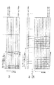
図1は、従来のMC−CDMA方式の送信装置1000の構成を示している。この送信装置1000は、適数台のデータチャネル生成回路100を備えている。データチャネル生成回路100各々では、送信データ発生部101から入力された送信データ系列を伝送路符号化器102において符号化し、データ変調部103においてデータ変調する。そして、変調されたデータ系列に多重部104においてパイロットシンボルを多重し、直並列変換部105において直並列変換して周波数軸上のN/SF個の情報シンボル系列にする。直並列変換された周波数軸上のN/SF個の情報シンボル系列は、コピー部106によって情報シンボル毎に短周期拡散符号の系列長と等しいシンボル数SF個ずつコピーされ、周波数軸上に並べられる。並べられた周波数軸上のN個の情報シンボル系列に対して、乗算器108にて短周期拡散符号生成器107の作成した短周期拡散符号を乗算する。
【0005】
合成部109において、データチャネル生成回路100各々から出力される各短周期拡散符号(ショートコード)の乗算された系列長Nの周波数軸上のシンボル系列を多重する。多重された系列長Nのシンボル系列に対して、N個の乗算器111各々においてスクランブルコード生成器110の出力するスクランブルコードを周波数方向に乗算し、逆フーリエ変換回路(IFFT)113に入力する。
【0006】
逆フーリエ変換回路113は、N個のサブキャリアの直交マルチキャリア信号に変換する。そして、このマルチキャリア信号にガードインターバル挿入器114によってGIを挿入する。そして送信装置1000はこのガードインターバル挿入器114の出力するマルチキャリア信号を無線信号にして空間に送出する。
【0007】
受信側である移動局では、送信装置1000から送信される無線マルチキャリア信号を受信し、受信したマルチキャリア信号から送信側で挿入されたガードインターバルを除去する。受信側ではさらに、ガードインターバルの除去されたマルチキャリア信号に対してFFT(Fast Fourier Transform)を行ってN個のサブキャリア成分に分離し、復調する。このため、受信側ではFFT前にガードインターバル部分の受信タイミング、すなわちFFTタイミングを検出する必要がある。
【0008】
OFDM変調方式を用いたマルチキャリア伝送方式におけるFFTタイミングの検出方式として、1シンボル毎に挿入されているガードインターバル部分の相関をとることによりFFTタイミングを検出する方法が知られている(「マルチキャリア変調信号のシンボル同期・周波数オフセット同時推定方式」、毛利、岡田、原、小牧、森永、情報通信学会技報 RCS95−70、pp.9−16、1995−09)。また、タイミング検出用信号として、同じ信号を2回繰り返して送信し、受信側で2シンボル間の相関をとることによりFFTタイミングを検出する方法が知られている(「高速無線LAN用OFDM変調方式の同期系に関する検討」、鬼沢、溝口、熊谷、高梨、守倉、情報通信学会技報 RCS97−210、pp.137−142、1998−01)。
【0009】
MC−CDMA方式では、通信者の識別は、通信者毎に割り当てられた短周期拡散符号で行う。このため、複数の通信者が同一の周波数帯を用いて同時に通信を行うことができる。
【0010】
【発明が解決しようとする課題】
上述したMC−CDMA方式を移動通信に用いる場合、基地局の識別を行うためにスクランブルコードを用いる必要がある。このため、MC−CDMA方式のための受信装置はFFTタイミングの検出と共にスクランブルコードの同定ができなければならない。これを可能にするためには、移動局側では、システムで用意される全てのスクランブルコードに対して相関を検出し、接続すべき基地局の信号に乗算されているスクランブルコードを検出する必要がある。柔軟なスクランブルコード割当てを考慮すると、システムで用意されるスクランブルコード数は数百程度となる。これに対応しようとすれば、移動局が通信を開始する際に、スクランブルコードの検出に長時間を要してしまうことになる。しかしながら、現在までのところ、MC−CDMAの研究は主にリンクレベルの評価に関連するものであり、スクランブルコードの同定に関連するものは見られない。
【0011】
本発明は、このような問題点を解決するためになされたもので、その目的とするところは、複数の基地局それぞれを識別するためのスクランブルコードを用いたMC−CDMA方式において、受信局側において拡散符号を高速・高精度に検出することができる移動通信システムにおける送信技術及び受信技術を提供することにある。
【0012】
本発明はまた、MC−CDMA方式の移動通信システムにおいて、受信側で最適な基地局として複数の候補を設けることにより最適セルのFFTタイミングを検出することができる信号の受信技術を提供することを目的とする。
【0013】
【課題を解決するための手段】
かかる目的を達成するための本発明の第1の特徴は、複数の送信用データ系列それぞれに複数の短周期拡散符号それぞれを乗積する短周期拡散符号乗積部と、前記短周期拡散符号乗積部から出力される短周期拡散符号の乗積された前記複数の送信用データ系列それぞれに共通する長周期拡散符号を乗積する長周期拡散符号乗積部と、同期信号用データに同期信号用拡散符号を乗積して出力する同期信号生成部と、前記長周期拡散符号乗積部から出力される短周期拡散符号と長周期拡散符号とが二重に乗積された前記送信用データ系列それぞれを、複数のサブキャリアを用いて送出すると共に、前記同期信号生成部の出力する同期信号用データに同期信号用拡散符号のみが乗積された同期信号を、1または複数のサブキャリアを用いて送出する送信処理部とを備えて成るMC−CDMA方式の移動通信システムにおける送信装置である。
【0014】
本発明の第2の特徴は、短周期拡散符号と長周期拡散符号とを二重に乗積したデータ系列を、複数のサブキャリアを用いて送信すると共に、同期信号用拡散符号のみで乗積された同期信号を、1または複数のサブキャリアを用いて送信することを特徴とする移動通信システムにおける送信方法である。
【0015】
本発明の第3の特徴は、短周期拡散符号と長周期拡散符号群に含まれるいずれか1つの長周期拡散符号とを二重に乗積したデータ系列を、複数のサブキャリアを用いて伝送するMC−CDMA方式の移動通信システムにおける受信装置であって、1または複数のサブキャリアに、同期信号用拡散符号のみが乗積された同期信号を含むマルチキャリア信号を受信する信号受信部と、前記信号受信部が受信した前記マルチキャリア信号と、同期信号レプリカとの相関値を求める相関器と、前記相関器が求めた前記相関値に応じて、FFTタイミングと前記長周期拡散符号の受信タイミングとを検出するタイミング検出部とを備えたものである。
【0016】
本発明の第4の特徴は、短周期拡散符号と長周期拡散符号群に含まれるいずれか1つの長周期拡散符号とを二重に乗積したデータ系列を、複数のサブキャリアを用いて伝送するMC−CDMA方式の移動通信システムにおける受信装置であって、1または複数のサブキャリアに、同期信号用拡散符号のみが乗積された同期信号を含むマルチキャリア信号を受信する信号受信部と、前記信号受信部が受信した前記マルチキャリア信号と、同期信号レプリカとの相関値を求める第1の相関器と、前記第1の相関器が求めた前記相関値に応じて、FFTタイミングと前記長周期拡散符号の受信タイミングとを検出するタイミング検出部と、前記タイミング検出部が検出した前記FFTタイミングに応じてFFTを行い、前記マルチキャリア信号を複数のサブキャリア成分に分離するFFT回路と、前記タイミング検出部が検出した前記長周期拡散符号の受信タイミングに応じて、前記FFT回路が分離した前記複数のサブキャリア成分と、前記長周期拡散符号群に含まれる各々の長周期拡散符号と前記短周期拡散符号とを二重に乗積した符号系列との相関値を求める第2の相関器と、前記第2の相関器が求めた前記相関値に応じて、前記マルチキャリア信号を拡散する長周期拡散符号を検出する符号検出部と、前記タイミング検出部が検出した前記長周期拡散符号の受信タイミングと前記符号検出部が検出した前記長周期拡散符号とを用いて、前記信号受信部が受信した前記マルチキャリア信号から前記データ系列を復調する復調回路とを備えたものである。
【0017】
本発明の第5の特徴は、短周期拡散符号と長周期拡散符号群に含まれるいずれか1つの長周期拡散符号とを二重に乗積したデータ系列を、複数のサブキャリアを用いて伝送するMC−CDMA方式の移動通信システムにおける受信装置であって、1または複数のサブキャリアに、同期信号用拡散符号のみが乗積された同期信号を含むマルチキャリア信号を受信する信号受信部と、前記信号受信部が受信した前記マルチキャリア信号を、複数のサブキャリア成分に分離するサブキャリア分離部と、前記サブキャリア分離部が分離した前記複数のサブキャリア成分のうち、前記同期信号を含むサブキャリア成分と同期信号レプリカとの相関値を求める相関器と、前記相関器が求めた前記相関値に応じて、前記長周期拡散符号の受信タイミングを検出するタイミング検出部とを備えたものである。
【0018】
本発明の第6の特徴は、短周期拡散符号と長周期拡散符号群に含まれるいずれか1つの長周期拡散符号とを二重に乗積したデータ系列を、複数のサブキャリアを用いて伝送するMC−CDMA方式の移動通信システムにおける受信装置であって、1または複数のサブキャリアに、同期信号用拡散符号のみが乗積された同期信号を含むマルチキャリア信号を受信する信号受信部と、前記信号受信部が受信した前記マルチキャリア信号を、複数のFFTタイミングに応じてFFTを行い、複数のサブキャリア成分に分離するサブキャリア分離部と、前記サブキャリア分離部が分離した前記複数のサブキャリア成分のうち、前記同期信号に含まれるサブキャリア成分と同期信号レプリカとの相関値を求める相関器と、前記相関器が求めた相関値に応じて、前記長周期拡散符号の受信タイミングとFFTタイミングとを検出するタイミング検出部とを備えたものである。
【0019】
本発明の第7の特徴は、短周期拡散符号と長周期拡散符号群に含まれるいずれか1つの長周期拡散符号とを二重に乗積したデータ系列を、複数のサブキャリアを用いて伝送するMC−CDMA方式の移動通信システムにおける受信装置であって、1または複数のサブキャリアに、同期信号用拡散符号のみが乗積された同期信号を含むマルチキャリア信号を受信する信号受信部と、前記信号受信部が受信した前記マルチキャリア信号を、複数のサブキャリア成分に分離するサブキャリア分離部と、前記サブキャリア分離部が分離した前記複数のサブキャリア成分のうち、前記同期信号を含むサブキャリア成分と同期信号レプリカとの相関値を求める第1の相関器と、前記第1の相関器が求めた前記相関値に応じて、前記長周期拡散符号の受信タイミングを検出するタイミング検出部と、前記タイミング検出部が検出した前記長周期拡散符号の受信タイミングに応じて、前記サブキャリア分離部が分離した前記複数のサブキャリア成分と、前記長周期拡散符号群に含まれる各々の長周期拡散符号と前記短周期拡散符号とを二重に乗積した符号系列との相関値を求める第2の相関器と、前記第2の相関器が求めた相関値に応じて、前記マルチキャリア信号を拡散する長周期拡散符号を検出する符号検出部と、前記タイミング検出部が検出した前記長周期拡散符号の受信タイミングと前記符号検出部が検出した前記長周期拡散符号とを用いて、前記信号受信部が受信した前記マルチキャリア信号から前記データ系列を復調する復調回路とを備えたものである。
【0020】
本発明の第8の特徴は、短周期拡散符号と長周期拡散符号群に含まれるいずれか1つの長周期拡散符号とを二重に乗積したデータ系列を、複数のサブキャリアを用いて伝送するMC−CDMA方式の移動通信システムにおける受信装置であって、1または複数のサブキャリアに、同期信号用拡散符号のみが乗積された同期信号を含むマルチキャリア信号を受信する信号受信部と、前記信号受信部が受信した前記マルチキャリア信号を、複数のFFTタイミングに応じてFFTを行い、複数のサブキャリア成分に分離するサブキャリア分離部と、前記サブキャリア分離部が分離した前記複数のサブキャリア成分のうち、前記同期信号に含まれるサブキャリア成分と同期信号レプリカとの相関値を求める第1の相関器と、前記第1の相関器が求めた相関値に応じて、前記長周期拡散符号の受信タイミングとFFTタイミングとを検出するタイミング検出部と、前記タイミング検出部が検出した前記FFTタイミングに応じてFFTを行い、前記マルチキャリア信号を複数のサブキャリア成分に分離するFFT回路と、前記タイミング検出部が検出した前記長周期拡散符号の受信タイミングに応じて、前記FFT回路が分離した複数のサブキャリア成分と、前記長周期拡散符号群に含まれる各々の長周期拡散符号と前記短周期拡散符号とを二重に乗積した符号系列との相関値を求める第2の相関器と、前記第2の相関器が求めた前記相関値に応じて、前記マルチキャリア信号を拡散する長周期拡散符号を検出する符号検出部と、前記タイミング検出部が検出した前記長周期拡散符号の受信タイミングと前記符号検出部が検出した前記長周期拡散符号とを用いて、前記信号受信部が受信した前記マルチキャリア信号から前記データ系列を復調する復調回路とを備えたものである。
【0021】
本発明の第9の特徴は、短周期拡散符号と長周期拡散符号群に含まれるいずれか1つの長周期拡散符号とを二重に乗積したデータ系列を、複数のサブキャリアを用いて伝送するMC−CDMA方式の移動通信システムにおける受信装置であって、1または複数のサブキャリアに、同期信号用拡散符号のみが乗積された同期信号を含むマルチキャリア信号を受信する信号受信部と、前記信号受信部が受信した前記マルチキャリア信号を、複数のFFTタイミングそれぞれに応じてFFTを行い、複数組の複数のサブキャリア成分に分離するサブキャリア分離部と、前記サブキャリア分離部が分離した前記複数のサブキャリア成分のうち、前記同期信号を含むサブキャリア成分と同期信号レプリカとの相関値を求める第1の相関器と、前記相関器が求めた前記相関値に応じて、前記長周期拡散符号の複数個の受信タイミング候補を検出するタイミング検出部と、前記タイミング検出部が検出した前記複数の長周期拡散符号の受信タイミングそれぞれに応じて、前記複数組それぞれの複数のサブキャリア成分と、前記長周期拡散符号群に含まれる各々の長周期拡散符号と前記短周期拡散符号とを二重に乗積した符号系列との相関値を求める第2の相関器と、前記第2の相関器が求めた前記複数の相関値それぞれに応じて、前記マルチキャリア信号を拡散する複数の長周期拡散符号候補それぞれを検出する符号候補検出部と、前記タイミング検出部が検出した複数個の受信タイミング候補と、前記符号候補検出部が検出した複数の長周期拡散符号候補とから、前記長周期拡散符号の受信タイミングと前記長周期拡散符号とを検出するタイミング及び符号検出部と、前記タイミング及び符号検出部が検出した前記長周期拡散符号の受信タイミングと前記長周期拡散符号とを用いて、前記信号受信部が受信した前記マルチキャリア信号から前記データ系列を復調する復調回路とを備えたものである。
【0022】
本発明の第10の特徴は、短周期拡散符号と長周期拡散符号群に含まれるいずれか1つの長周期拡散符号とを二重に乗積したデータ系列を、複数のサブキャリアを用いて伝送するMC−CDMA方式の移動通信システムにおける受信装置であって、1または複数のサブキャリアに、同期信号用拡散符号のみが乗積された同期信号を含むマルチキャリア信号を受信する信号受信部と、前記信号受信部が受信した前記マルチキャリア信号のガードインターバル部分の相関を検出し、FFTタイミングを検出するFFTタイミング検出部と、前記FFTタイミング検出部が検出した前記FFTタイミングにおいてFFTを行い、複数のサブキャリア成分に分離するサブキャリア分離部と、前記サブキャリア分離部が分離した前記複数のサブキャリア成分のうち、前記同期信号を含むサブキャリア成分と同期信号レプリカとの相関値を求める相関器と、前記相関器が求めた相関値に応じて、前記長周期拡散符号の受信タイミングを検出するタイミング検出部とを備えたものである。
【0023】
本発明の第11の特徴は、短周期拡散符号と長周期拡散符号群に含まれるいずれか1つの長周期拡散符号とを二重に乗積したデータ系列を、複数のサブキャリアを用いて伝送するMC−CDMA方式の移動通信システムにおける受信装置であって、1または複数のサブキャリアに、同期信号用拡散符号のみが乗積された同期信号を含むマルチキャリア信号を受信する信号受信部と、前記信号受信部が受信した前記マルチキャリア信号から、それが含むガードインターバルの相関特性に基づいてFFTタイミングを検出するFFTタイミング検出部と、前記FFTタイミング検出部が検出した前記FFTタイミングにおいてFFTを行い、複数のサブキャリア成分に分離するサブキャリア分離部と、前記サブキャリア分離部が分離した前記複数のサブキャリア成分のうち、前記同期信号を含むサブキャリア成分と同期信号レプリカとの相関値を求める第1の相関器と、前記第1の相関器が求めた相関値に応じて、前記長周期拡散符号の受信タイミングを検出するタイミング検出部と、前記タイミング検出部が検出した前記長周期拡散符号の受信タイミングに応じて、前記サブキャリア分離部が分離したサブキャリア成分と、前記長周期拡散符号群に含まれる各々の長周期拡散符号と前記短周期拡散符号とを二重に乗積した符号系列との相関値を求める第2の相関器と、前記第2の相関器が求めた前記相関値に応じて、前記マルチキャリア信号を拡散する長周期拡散符号を検出する符号検出部と、前記タイミング検出部が検出した前記長周期拡散符号の受信タイミングと前記符号検出部が検出した前記長周期拡散符号とを用いて、前記信号受信部が受信した前記マルチキャリア信号から前記データ系列を復調する復調回路とを備えたものである。
【0024】
本発明の第12の特徴は、短周期拡散符号と長周期拡散符号群に含まれるいずれか1つの長周期拡散符号とを二重に乗積したデータ系列を、複数のサブキャリアを用いて伝送する移動通信システムにおける受信方法において、1または複数のサブキャリアに同期信号用拡散符号のみで乗積された同期信号を有する前記複数のサブキャリアが含まれる受信信号を受信する受信ステップと、該受信ステップで受信された前記受信信号と、同期信号レプリカとの相関値を出力する相関出力ステップと、該相関出力ステップで出力された相関値に応じて、FFTタイミングと前記長周期拡散符号の受信タイミングを検出するタイミング検出ステップとを有するものである。
【0025】
上記の移動通信システムにおける受信方法においては、さらに、前記タイミング検出ステップで検出された前記FFTタイミングに応じてFFTを行い、前記受信信号を複数のサブキャリア成分に分離する分離ステップと、前記タイミング検出ステップで検出された前記長周期拡散符号の受信タイミングに応じて、前記サブキャリア成分と、前記長周期拡散符号群に含まれる各々の長周期拡散符号と前記短周期拡散符号とを二重に乗積した符号系列との相関検出値を出力する相関検出ステップと、該相関検出ステップから出力された相関検出値に応じて、前記受信信号を拡散する長周期拡散符号を検出する符号検出ステップとを有するものとすることができる。
【0026】
本発明の第13の特徴は、短周期拡散符号と長周期拡散符号群に含まれるいずれか1つの長周期拡散符号とを二重に乗積したデータ系列を、複数のサブキャリアを用いて伝送する移動通信システムにおける受信方法において、1または複数のサブキャリアに同期信号用拡散符号のみで乗積された同期信号を有する前記複数のサブキャリアが含まれる受信信号を受信する受信ステップと、該受信ステップで受信された前記受信信号を、複数のサブキャリア成分に分離する分離ステップと、該分離ステップで分離された前記複数のサブキャリア成分のうち、前記同期信号に含まれるサブキャリア成分と同期信号レプリカとの相関値を出力する相関出力ステップと、該相関出力ステップで出力された相関値に応じて、前記長周期拡散符号の受信タイミングを検出するタイミング検出ステップとを有するものである。
【0027】
上記の移動通信システムにおける受信方法において、前記分離ステップは、複数のFFTタイミングに応じてFFTを行い、前記タイミング検出ステップは、全ての前記FFTタイミングについて、前記相関出力ステップで出力された相関値に応じて、目的とするFFTタイミングと前記長周期拡散符号の受信タイミングを検出し、さらに、前記タイミング検出ステップで検出された前記FFTタイミングに応じてFFTを行い、前記受信信号を複数のサブキャリア成分に分離する分離ステップと、前記タイミング検出ステップで検出された前記長周期拡散符号の受信タイミングに応じて、前記サブキャリア成分と、前記長周期拡散符号群に含まれる各々の長周期拡散符号と前記短周期拡散符号とを二重に乗積した符号系列との相関検出値を出力する相関検出ステップと、該相関検出ステップから出力された相関検出値に応じて、前記受信信号を拡散する長周期拡散符号を検出する符号検出ステップとを有するものとすることができる。
【0028】
本発明の第14の特徴は、短周期拡散符号と長周期拡散符号群に含まれるいずれか1つの長周期拡散符号とを二重に乗積したデータ系列を、複数のサブキャリアを用いて伝送する移動通信システムにおける受信方法において、1または複数のサブキャリアに同期信号用拡散符号のみで乗積された同期信号を有する前記複数のサブキャリアが含まれる受信信号を受信する受信ステップと、前記受信ステップで受信された前記受信信号を、複数のFFTタイミングに応じてFFTを行い、複数のサブキャリア成分に分離する分離ステップと、該分離ステップで分離された前記複数のサブキャリア成分のうち、前記同期信号に含まれるサブキャリア成分と同期信号レプリカとの相関値を出力する相関出力ステップと、該相関出力ステップで出力された相関値に応じて、前記長周期拡散符号の受信タイミングを検出するタイミング検出ステップと、該タイミング検出ステップで検出された前記長周期拡散符号の受信タイミングに応じて、前記サブキャリア成分と、前記長周期拡散符号群に含まれる各々の長周期拡散符号と前記短周期拡散符号とを二重に乗積した符号系列との相関検出値を出力する相関検出ステップと、全ての前記FFTタイミングについて、前記相関検出ステップから出力された相関検出値に応じて、前記FFTタイミングと、前記長周期拡散符号の受信タイミングと、前記受信信号を拡散する長周期拡散符号とを検出する符号検出ステップとを有するものである。
【0029】
本発明の第15の特徴は、短周期拡散符号と長周期拡散符号群に含まれるいずれか1つの長周期拡散符号とを二重に乗積したデータ系列を、複数のサブキャリアを用いて伝送する移動通信システムにおける受信方法において、受信信号のガードインターバル部分の相関を検出し、FFTタイミングを検出するFFTタイミング検出ステップと、該FFTタイミング検出ステップで得られたFFTタイミングにおいて、FFTを行い、複数のサブキャリア成分に分離する分離ステップと、該分離ステップで分離された前記複数のサブキャリア成分のうち、前記同期信号に含まれるサブキャリア成分と同期信号レプリカとの相関値を出力する相関出力ステップと、該相関出力ステップで出力された相関値に応じて、前記長周期拡散符号の受信タイミングを検出するタイミング検出ステップとを有するものである。
【0030】
上記の移動通信システムにおける受信方法においては、さらに、前記タイミング検出ステップで検出された長周期拡散符号の受信タイミングに応じて、前記サブキャリア成分と、前記長周期拡散符号群に含まれる各々の長周期拡散符号と前記短周期拡散符号とを二重に乗積した符号系列との相関検出値を出力する相関検出ステップと、該相関検出ステップから出力された相関検出値に応じて、前記受信信号を拡散する長周期拡散符号を検出する符号検出ステップとを有するものとすることができる。
【0031】
本発明の第16の特徴は、短周期拡散符号と長周期拡散符号群に含まれるいずれか1つの長周期拡散符号とを二重に乗積したデータ系列を、複数のサブキャリアを用いて伝送するMC−CDMA方式の移動通信システムにおける受信装置であって、1または複数のサブキャリアに、同期信号用拡散符号のみが乗積された同期信号を含むマルチキャリア信号を受信する信号受信部と、前記信号受信部が受信した前記マルチキャリア信号から、それが含むガードインターバルの相関特性に基づいて複数のFFTタイミング候補を検出するFFTタイミング検出部とを備え、前記FFTタイミング検出部は、前記マルチキャリア信号と当該マルチキャリア信号を1シンボル長遅延させた信号とを乗算する乗算部と、前記乗算部が乗算した乗算値を1ガードインターバル長に渡り積分して相関値を得る積分器と、前記積分器が求めた相関値とそのタイミングとを記憶する第1のメモリと、順次与えられる複数のFFTタイミング候補を記憶する第2のメモリと、前記第2のメモリに記憶されている複数のFFTタイミング候補及び前記第1のメモリの記憶値に基づいて前記複数のFFTタイミング候補それぞれのサーチ範囲を設定するサーチ範囲設定部と、始めに、前記第1のメモリの記憶値から最大相関値及びタイミングを選択し、前記FFTタイミング候補#1として前記第2のメモリに記憶し、次に、前記サーチ範囲設定部に、前記第2のメモリに記憶されているFFTタイミング候補及び前記第1のメモリの記憶値に基づいてサーチ範囲を設定させ、当該サーチ範囲内で前記第1のメモリの記憶値から最大相関値及びタイミングを選択し、FFTタイミング候補#2として前記第2のメモリに記憶させ、同様の手順で、あらかじめ設定された所定個数のFFTタイミング候補を検出するまで検出を繰り返すタイミング検出回路とを備えたものである。
【0032】
上記のMC−CDMA方式の移動通信システムにおける受信装置においては、さらに、前記FFTタイミング検出部が検出した前記所定個数のFFTタイミング候補それぞれにおいて前記マルチキャリア信号に対してFFTを行い、複数のサブキャリア成分に分離する複数のサブキャリア分離部と、前記複数のサブキャリア分離部それぞれが分離した前記複数のサブキャリア成分のうち、前記同期信号を含むサブキャリア成分と同期信号レプリカとの相関値を求める複数の第1の相関器と、前記複数の第1の相関器それぞれが求めた相関値に応じて、長周期拡散符号の受信タイミング候補を検出する複数のタイミング検出部と、前記複数のタイミング検出部それぞれが検出した前記複数の長周期拡散符号の受信タイミング候補それぞれに応じて、前記複数のサブキャリア成分と、前記長周期拡散符号群に含まれる各々の長周期拡散符号と前記短周期拡散符号とを二重に乗積した符号系列との相関値を求める複数の第2の相関器と、前記複数の第2の相関器それぞれが求めた前記複数の相関値それぞれに応じて、前記マルチキャリア信号を拡散する複数の長周期拡散符号候補それぞれを検出する複数の符号候補検出部と、前記複数のタイミング検出部が検出した前記複数の受信タイミング候補と、前記複数の符号候補検出部が検出した前記複数の長周期拡散符号候補とから、前記長周期拡散符号の受信タイミングと前記長周期拡散符号とを検出するタイミング及び符号検出部と、前記タイミング及び符号検出部が検出した前記長周期拡散符号の受信タイミングと前記長周期拡散符号とを用いて、前記信号受信部が受信した前記マルチキャリア信号から前記データ系列を復調する復調回路とを備えたものとすることができる。
【0033】
上記のMC−CDMA方式の移動通信システムにおける受信装置においては、さらに、前記FFTタイミング検出部が検出した前記所定個数のFFTタイミング候補それぞれにおいて前記マルチキャリア信号に対してFFTを行い、複数のサブキャリア成分に分離する複数の第1のFFT回路と、前記複数の第1のFFT回路それぞれが分離した前記複数のサブキャリア成分のうち、前記同期信号を含むサブキャリア成分と同期信号レプリカとの相関値を求める複数の第1の相関器と、前記複数の第1の相関器それぞれが求めた相関値に応じて、前記長周期拡散符号の受信タイミングとFFTタイミングとを検出するタイミング検出部と、前記タイミング検出部が検出した前記FFTタイミングに応じてFFTを行い、前記マルチキャリア信号を複数のサブキャリア成分に分離する第2のFFT回路と、前記タイミング検出部が検出した前記長周期拡散符号の受信タイミングに応じて、前記第2のFFT回路が分離した複数のサブキャリア成分と、前記長周期拡散符号群に含まれる各々の長周期拡散符号と前記短周期拡散符号とを二重に乗積した符号系列との相関値を求める第2の相関器と、前記第2の相関器が求めた前記相関値に応じて、前記マルチキャリア信号を拡散する長周期拡散符号を検出する符号検出部と、前記タイミング検出部が検出した前記長周期拡散符号の受信タイミングと前記符号検出部が検出した前記長周期拡散符号とを用いて、前記信号受信部が受信した前記マルチキャリア信号から前記データ系列を復調する復調回路とを備えたものとすることもできる。
【0034】
本発明の第17の特徴は、符号系列を、複数のサブキャリアを用いて伝送する移動通信システムにおける信号の受信方法において、ガードインターバルの相関特性より、複数のFFTタイミング候補を検出するステップを有するものである。
【0035】
本発明の第18の特徴は、符号系列を、複数のサブキャリアを用いて伝送する移動通信システムにおける信号の受信方法において、受信信号と、受信信号を1シンボル長遅延させた信号とを乗算するステップと、得られた乗算値を、平均区間をガードインターバル長として移動平均するステップと、移動平均により得られた複数の相関値の相関系列をガードインターバル挿入周期毎に同相加算するステップと、同相加算により得られたガードインターバル挿入周期と等しい長さの相関系列の中から複数個のFFTタイミング候補を検出するステップとを有するものである。
【0036】
上記の複数個のFFTタイミング候補を検出するステップは、同相加算により得られたガードインターバル挿入周期と等しい長さの相関系列の中で、最大の相関値を有するタイミングを第1のFFTタイミング候補とするステップと、第2以降のFFTタイミング候補各々は、既に検出されたFFTタイミング候補各々の周辺Wサンプルを除外ウィンドウとして除外した残りの相関系列の中で最大の相関値を有するタイミングを次のFFTタイミング候補とする方法を繰り返すことによって、所定個数分まで検出するステップとを有するものとすることができる。
【0037】
本発明の第19の特徴は、符号系列を、複数のサブキャリアを用いて伝送する移動通信システムにおける信号の受信方法において、ガードインターバルの相関特性より、複数のFFTタイミング候補を検出するステップと、複数のFFTタイミング候補においてFFTを行い、複数のサブキャリア成分に分離するステップと、分離された複数のサブキャリア成分のうち、同期信号が含まれるサブキャリア成分と同期信号レプリカとの相関値を出力するステップと、出力された相関値に応じて、長周期拡散符号の受信タイミング候補を1又は複数個検出するステップと、検出された1又は複数個の長周期拡散符号の受信タイミング候補に応じて、サブキャリア成分と、長周期拡散符号群に含まれる各々の長周期拡散符号と短周期拡散符号とを二重に乗積した符号系列との相関検出値を出力するステップと、検出したすべてのFFTタイミング候補について、出力された相関検出値に応じて、FFTタイミングと長周期拡散符号の受信タイミングと受信信号を拡散する長周期拡散符号とを検出するステップとを有するものである。
【0038】
本発明の第20の特徴は、短周期拡散符号と長周期拡散符号群に含まれるいずれか1つの長周期拡散符号とを二重に乗積したデータ系列を、複数のサブキャリアを用いて伝送する移動通信システムにおける信号の受信方法において、FFT等の処理により受信信号を各サブキャリア成分に分離した信号と前記長周期拡散符号群に含まれる各々の長周期拡散符号と前記短周期拡散符号とを二重に乗積した符号系列との相関検出値を出力する際に、サブキャリア毎に各シンボルの相関値を時間方向にNavgシンボル(Navgは1以上の整数)同相加算し、サブキャリア毎の同相加算値を周波数方向に隣接するNcsサブキャリア(Ncsは、1≦Ncs≦Nなる整数。ただし、Nはサブキャリア数)にわたり同相加算し、Ncsサブキャリア毎の同相加算値を周波数方向にNps個(Npsは、1≦Nps≦N/Ncsなる整数)電力加算することにより平均相関値を検出するものである。
【0039】
上記の移動通信システムにおける信号の受信方法においては、Nps<(N/Ncs)の場合、(N/Ncs)/Nps個の長周期拡散符号を周波数方向にNcsサブキャリア毎に交互に相関検出するものとすることができる。
【0040】
【発明の実施の形態】
以下、本発明の実施の形態を図に基づいて詳説する。図2は、MC−CDMA方式の移動通信システムにおいて利用される伝送信号のフレーム構成を示している。長周期拡散符号であるスクランブルコードは、周波数方向、時間方向ともに基地局毎に異なったパターンを持っている。
【0041】
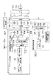
図3は、本発明の第1の実施の形態の移動通信システムに使用されるMC−CDMA方式の送信装置10.1の構成を示している。この送信装置10.1は無線信号を送信する基地局毎に備えられているものである。送信装置10.1は、複数のデータチャネル生成回路100.1〜100.xを備えている。データチャネル生成回路100各々では、送信データ発生部101から入力された送信データ系列を伝送路符号化器102において符号化し、データ変調部103においてデータ変調する。そして、変調されたデータ系列に多重部104においてパイロットシンボルを多重し、直並列変換部105において直並列変換して周波数軸上のN/SF個の情報シンボル系列にする。直並列変換された周波数軸上のN/SF個の情報シンボル系列は、コピー部106によって情報シンボル毎に短周期拡散符号の系列長と等しいシンボル数SF個ずつコピーされ、周波数軸上に並べられる。並べられた周波数軸上のN個の情報シンボル系列に対して、乗算器108にて短周期拡散符号生成器107の作成した短周期拡散符号を乗算する。
【0042】
第1の合成部109において、データチャネル生成回路100各々から出力される各短周期拡散符号の乗算された系列長Nの周波数軸上のシンボル系列を多重する。多重された系列長Nのシンボル系列に対して、N個の乗算器111各々においてスクランブルコード生成器110の出力するスクランブルコードを周波数方向に乗算し、第2の合成部112.1に出力する。第2の合成部112.1は、スクランブルコードが乗算された系列長Nのシンボル系列に、同期信号生成部120.1において作成された同期信号を合成する。
【0043】
逆フーリエ変換装置(IFFT)113は、N個のシンボルを直交マルチキャリア信号に変換する。ガードインターバル挿入器114はこのマルチキャリア信号にガードインターバルGIを挿入する。そして送信装置10.1はこのガードインターバル挿入器114の出力するマルチキャリア信号を無線信号にして空間に出力する。
【0044】
同期信号生成部120.1により、以下のようにして同期信号が生成される。データ発生部121は同期信号用のデータ(通常は全基地局で共通のデータで、全て1でも良い。)を生成する。データ変調部121はこの同期信号用データを変調する。同期信号用拡散符号生成器123は同期信号用拡散符号を生成する。乗算器124は、データ変調部121で変調されたデータ信号と同期信号用拡散符号生成器123の出力する同期信号用拡散符号とを乗算し、同期信号を生成して第2の合成部112.1に出力する。
【0045】
次に、この図3のMC−送信装置10.1によるマルチキャリア信号の送信方法を説明する。図4(a)は、同期信号生成部120.1が同期信号を特定の複数のサブキャリアにおいて時間方向に連続して送信する場合の例である。図5(b)は、同期信号生成部120.1が同期信号を特定の1つのサブキャリアにおいて時間方向に連続して送信する場合の例である。これらの同期信号S1は、データ発生部121の出力するデータ信号D1に対して、同期信号用拡散符号生成器123の与える同期信号用拡散符号C1を乗積した信号である。
【0046】
送信装置10.1における第2の合成部112.1は、同期信号生成部120.1の生成した同期信号S1をNサブキャリアのうちの該当する特定のサブキャリアにおいて時間軸上では連続的に多重する。そして、IFFT回路113によって逆フーリエ変換し、ガードインターバル挿入器114でフーリエ対象時間毎に一定長のシンボルガードインターバルGIを挿入してマルチキャリア信号として出力することになる。
【0047】
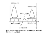
図5(a)も、同期信号を特定の1つのサブキャリアにおいて、時間方向に連続して送信する場合の例を示している。しかし、図5(a)は、同期信号生成部120.1において1スクランブルコードパターンの繰返し時間τと、同期信号のパターン長とを等しくした同期信号S2を生成する場合の例である。同期信号S2は時間方向にある特定のパターンを有するデータ系列を示している。特定のパターンは、同期信号用のスクランブルコードのパターンにより実現できる。従って、この送信方法で送信されるマルチキャリア信号を受信する受信移動局では、受信信号から同期信号S2の受信タイミングを検出することで、長周期拡散符号であるスクランブルコードの乗算開始タイミングの受信タイミングを検出することができる。
【0048】
図5(b)は、同期信号S3の長さが、1スクランブルコードパターンの繰返し時間τの1/2の場合の例を示している。この場合も、同期信号S3は時間方向にある特定のパターンを有する系列である。従って、移動局側では、受信信号から同期信号S3の送信タイミングを検出することで、スクランブルコードの乗算開始タイミングの受信タイミングを限定することができる。
【0049】
同期信号生成部120.1による同期信号は、図6(a),(b),(c)に示す方法で第2の合成部112.1において特定の1又は複数のサブキャリアにおいて時間軸上ではバースト的に多重することもできる。図6(a)は、同期信号S4を特定の複数のサブキャリアと合成し、同一のタイミングでバースト的に送信する場合の例である。図6(b)は、同期信号S4を特定の1つのサブキャリアと合成し、バースト的に送信する場合の例である。図6(c)は、同期信号S4を全てのサブキャリアに合成し、同一のタイミングでバースト的に送信する場合の例である。
【0050】
図7(a),(b)は、MC−CDMA伝送方式において用いられるさらに別の同期信号S5の送信方法を示す図である。図7(a)は、第2の合成部112.1において、同期信号生成部120.1の生成した一定パターンの同期信号S5をスクランブルコードの1周期毎に複数の特定のサブキャリアそれぞれに異なるタイミングで同期信号S5を多重し、バースト的に送信する場合の例である。このようなマルチキャリア信号を受信する移動局側では、図7(b)に示すように、受信信号から同期信号S5の送信されている複数のサブキャリアと、各同期信号S5の受信タイミングとを検出することで、そのスクランブルコードの乗算開始タイミングの受信タイミングを検出することができる。
【0051】
次に、本発明の第2の実施の形態のMC−CDMA方式の送信装置及び送信方法について、説明する。図8に示す送信装置10.2は、図3に示した送信装置と共通する要素には同一の符号を付して示してある。本実施の形態の特徴は、同期信号生成部120.1に直並列変換部125を備えた点にある。同期信号生成部120.2において、データ発生部121が同期信号用データ系列D1(通常は全基地局で共通のデータで、全て1でも良い。)を発生する。この同期信号用データD1をデータ変調部122においてデータ変調し、さらに、直並列変換部125において直並列変換して周波数軸上のN個のシンボル系列P1にする。シンボル系列P1の各信号に対して、同期信号用拡散符号生成器123において生成された同期信号用拡散符号C1を乗算器126各々に周波数方向に乗算し、N個の並列同期信号S6を生成して第2の合成部112.2に出力する。
【0052】
第2の合成部112.2は、同期信号生成部120.2からの生成した同期信号を特定のタイミングにおいて多重する。この多重化の方法は、図9(a),(b)に示してある。
【0053】
図9(a),(b)に示す送信方法は、同期信号S6を全てのサブキャリアにおいて、バースト的に送信する方法である。図9(a)は、1スクランブルコードパターンの開始時間と同期信号S6の送信タイミングとを同時にした場合である。従って、移動局側では、受信信号から同期信号S6の受信タイミングを検出することで、スクランブルコードの乗算開始タイミングの受信タイミングを検出することができる。図9(b)は、1スクランブルコードパターンの繰返し時間τ内に、2回同期信号S6を送信する場合である。この場合、同期信号S6の送信タイミング間隔が、スクランブルコードパターンの繰返し時間τの1/2である。従って、移動局側では、受信信号から同期信号S6の受信タイミングを検出することで、スクランブルコードの乗算開始タイミングの受信タイミングを限定することができる。
【0054】
次に、図10、図11、図12を用いて第3の実施の形態のMC−CDMA方式の移動通信システムにおける受信装置20.1の構成について説明する。受信装置20.1におけるスクランブルコード受信タイミング検出回路200.1は図11に示す内部構成であり、アンテナ199で受信されたマルチキャリア信号を入力し、スクランブルコード受信タイミングおよびFFTタイミングを検出して出力する。ガードインターバル除去回路208は、FFTタイミングに基づいてガードインターバルを除去する。FFT209は、高速フーリエ変換回路であり、GI除去回路208の出力する信号をN個のサブキャリア周波数に分解して出力する。スクランブル同定回路210.1は図11に示す内部構成であり、受信したマルチキャリア信号からスクランブルコードを同定する。復調回路300は図12に示す内部構成であり、スクランブルコード受信タイミング及びスクランブルコードを用いて受信したマルチキャリア信号を復調し、元の送信データを得る。
【0055】
図11を用いて、この送信装置20の詳しい構成を説明する。スクランブルコード受信タイミング検出回路200.1はアンテナ199で受信したマルチキャリア信号を相関器201に入力する。一方、同期信号レプリカ生成器202は、あらかじめ設定されている同期信号レプリカを生成し、相関器201に順次に入力する。相関器201において、受信したマルチキャリア信号と同期信号レプリカとの相関検出を行い、その結果得られた各ピークを示す相関値とそのタイミングを相関値とタイミングのメモリ203に記憶する。タイミング検出回路204は、相関値とタイミングのメモリ230内の記憶値から、最大相関値及びタイミングを選択し、スクランブルコード受信タイミングとしてメモリ205に記憶する。タイミング検出回路204はさらに、スクランブルコード受信タイミングよりFFTタイミングを計算し、FFTタイミングとしてメモリ205に記憶する。このメモリ205からFFTタイミングをGI除去回路208へ出力し、スクランブルコード受信タイミングをスクランブルコード同定回路210.1と復調回路300へ出力する。
【0056】
スクランブルコード受信タイミング検出回路200.1によるスクランブルコード受信タイミングの検出の後、GI除去回路208はメモリ205から出力されたFFTタイミングを用いて、GIを除去する。GIを除去されたマルチキャリア信号はFFT回路209に入力され、元のN個のサブキャリア成分に分離され、スクランブルコード同定回路210.1に入力される。
【0057】
スクランブルコード同定回路210.1においては、スクランブルコードレプリカ生成器211は所定の演算によりあらかじめ設定されている複数種、例えば、512種の位相を、スクランブルコード受信タイミング検出回路から得られる同期位相にセットする。サブキャリア個数分の相関器212は、スクランブルコードレプリカ生成器211で生成されたスクランブルコードレプリカとFFT回路209の出力との相関をサブキャリア毎に検出し、相関検出値を加算器213へ入力する。加算器213では、各サブキャリアにおける相関値を加算し、相関値とそのスクランブルコード番号を相関値とコード番号のメモリ214に記憶する。
【0058】
スクランブルコード検出回路215は、相関値とコード番号のメモリ214の記憶値から、最大相関値及びコード番号を選択し、同定したスクランブルコード番号を復調回路300へ出力する。
【0059】さらに、図12を用いて復調回路300の詳しい構成を説明する。受信されたマルチキャリア信号は図11の回路へ入力される。図11の回路から出力されたスクランブルコードの受信タイミング及び番号は、復調回路300へのスクランブルコード生成器301へ入力される。
【0060】
一方、受信されたマルチキャリア信号は、復調回路300のFFTタイミング検出部302にも入力される。そしてFFTタイミング検出部302はマルチキャリア信号のFFTタイミングを検出し、ガードインターバル除去器(−GI)303によってマルチキャリア信号からGIを除去する。FFT回路304は、ガードインターバルが除去されたマルチキャリア信号を各サブキャリア成分に分離する。チャネル推定部305は、各サブキャリアのチャネル変動値を推定した後、チャネル変動を乗算器306によって補償する。チャネル変動補償された各サブキャリアのシンボルに対して、乗算器307においてスクランブルコード生成器301の生成するスクランブルコードをサブキャリア方向に乗算する。さらにスクランブルコードが乗算されたシンボルに対して、乗算器308において対応するショートコードをサブキャリア方向に乗算する。ショートコードはショートコード生成器309によって与えられる。合成器310は、SF個のシンボルを合成して逆拡散する。逆拡散されたシンボルは、並直列変換器(P/S)311によって並直列変換され、さらに復調部312及び復号器313において復元されて元のデータが取り出される。
【0061】
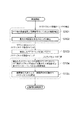
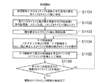
上記の構成のMC−CDMA方式の移動通信システムにおける受信装置20.1によるマルチキャリア信号の受信方法について、次に説明する。図13は、図10の受信装置20.1による信号の受信処理を示すフローチャートである。初めにFFTを行う前の全てのサブキャリア成分を含む受信信号と、同期信号レプリカとの相関を検出する(S101)。最大の相関値を得るタイミングにより、FFTタイミングすなわちシンボルタイミング、及びスクランブルコードの受信タイミングを同時に求める(S102)。
【0062】
続いて、検出したFFTタイミングにおいてFFTを行って受信信号を各サブキャリア成分に分離する(S103)。また、検出したスクランブルコードの受信タイミングにおいて、FFT後の各サブキャリア成分に分離された受信信号と、各スクランブルコードとの相関を検出し(S104)、最大の相関値を有するスクランブルコードを、受信信号を拡散するスクランブルコードとして検出する(S105)。
【0063】
受信装置20.1における復調回路300は、こうして検出したスクランブルコードを用いてマルチキャリア信号に対するディスクランブルを行い、さらにデータ信号を復調、復号して元のデータ系列を取り出す。
【0064】
次に、本発明の第4の実施の形態のMC−CDMA方式の移動通信システムにおける受信装置について、図14を用いて説明する。第4の実施の形態の受信装置20.2は、図10に示した受信装置20.1と機能ブロックの構成は同様であるが、スクランブルコード受信タイミング検出回路とスクランブルコード同定回路との構成が異なっている。これについて説明する。
【0065】
スクランブルコード受信タイミング検出回路200.2は、マルチキャリア信号を受信し、複数の同期信号相関検出回路2010.1〜2010.mへ入力する。一方、FFTタイミング設定回路2014では、各同期信号相関検出回路2010.x(x=1,2,…,m)に対して、FFTタイミングを設定する。各同期信号相関検出回路2010.xでは、ガードインターバル除去回路2015により、FFTタイミングを用いてマルチキャリア信号からGIを除去する。GIを除去されたマルチキャリア信号はFFT回路2016に入力され、FFT回路2016によって複数のサブキャリア成分に分離される。分離された各サブキャリア成分のうち、同期チャネルが多重されているサブキャリア成分のみを相関器2012に入力する。一方、同期信号レプリカ生成器2013は、同期信号レプリカを生成し、相関器2012に入力する。相関器2012は、FFT出力と同期信号レプリカの相関検出を行い、各サブキャリアにおける相関値を加算器207に入力する。加算器207では、各サブキャリアにおける相関値を加算し、相関値とそのタイミングをメモリ203に記憶する。
【0066】
タイミング検出回路204は、m個の相関値とタイミングのメモリ203内の記憶値から、最大相関値及びタイミングを選択し、スクランブルコード受信タイミングとしてメモリ205に記憶する。タイミング検出回路204はさらに、スクランブルコード受信タイミングよりFFTタイミングを計算し、FFTタイミングとしてメモリ205に記憶する。このメモリ205からFFTタイミングをGI除去回路208へ出力し、スクランブルコード受信タイミングをスクランブルコード同定回路210.1と復調回路300へ出力する。
【0067】
スクランブルコード受信タイミング検出回路200.2によるスクランブルコード受信タイミングの検出の後、GI除去回路208でGIを除去し、FFT回路209でFFTを行い、スクランブルコード同定回路210.1でスクランブルコード番号を特定して復調回路300へ出力する処理は図11と同じ回路による。また、復調回路300によるデータ復調処理は、図12と同じ回路による。
【0068】
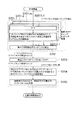
上記の構成の受信装置20.2によるマルチキャリア信号の受信方法について、次に説明する。図15は、図10及び図14に示す受信装置20.2によるマルチキャリア信号の受信処理を示すフローチャートである。あるFFTタイミングにおいてFFTを行い(S2011.1)、あるFFTタイミングにおけるFFT後の信号について、同期信号を送信しているサブキャリア成分と同期信号レプリカとの相関を検出する(S2012.1)。これを、複数のFFTタイミングにおいて行う(S201.1〜S201.m)。全てのFFTタイミングにおいて検出した相関値において、最大の相関値を得るタイミングにより、スクランブルコードの受信タイミングを求める。また、最大の相関値を検出したFFTタイミングにより、FFTタイミングを検出する(S202)。
【0069】
次に、検出したFFTタイミングにおいてFFTを行い(S203)、受信信号を各サブキャリア成分に分離する。検出したスクランブルコードの受信タイミングにおいて、FFT後の各サブキャリア成分に分離された受信信号と、各スクランブルコードとの相関を検出し(S204)、最大の相関値を有するスクランブルコードを、受信信号を拡散するスクランブルコードとして検出する(S205)。
【0070】
続いて、受信装置20.2における復調回路300は、こうして検出したスクランブルコードを用いてマルチキャリア信号に対するディスクランブルを行い、さらにデータ信号を復調、復号して元のデータ系列を取り出すのである。
【0071】
次に、本発明の第5の実施の形態の受信装置について、図16及び図12を用いて説明する。第4の実施の形態の受信装置20.3は、スクランブルコード受信タイミング検出回路200.3とスクランブルコード同定回路210.1と、復調回路300によって構成される。
【0072】
スクランブルコード受信タイミング検出回路200.3は、マルチキャリア信号を受信し、DFT回路等2011を用いて各サブキャリア成分に分離する。分離された各サブキャリア成分のうち、同期チャネルが多重されているサブキャリア成分のみを相関器2012に入力する。一方、同期信号レプリカ生成器2013は同期信号レプリカを生成し、相関器2012に入力する。相関器2012において、DFT回路2011からのサブキャリア成分各々と同期信号レプリカとの相関検出を行い、各サブキャリアにおける相関値を加算器207に入力する。加算器207は、各サブキャリアにおける相関値を加算し、相関値とそのタイミングを相関値とタイミングのメモリ203に記憶する。タイミング検出回路204は、相関値とタイミングのメモリ230内の記憶値から、最大相関値及びタイミングを選択し、スクランブルコード受信タイミングとしてメモリ205に記憶する。このメモリ205からスクランブルコード受信タイミングをスクランブルコード同定回路210.1へ出力する。
【0073】
スクランブル同定回路210.1の構成は図14のものと同様である。スクランブルコードレプリカ生成器211は所定の演算によりあらかじめ設定されている複数種の位相を、スクランブルコード受信タイミング検出回路200.3から得られる同期位相にセットする。サブキャリア個数分の相関器212は、スクランブルコードレプリカ生成器211で生成されたスクランブルコードレプリカとDFT回路2011の出力との相関をサブキャリア毎に検出し、相関検出値を加算器213へ入力する。加算器213では、各サブキャリアにおける相関値を加算し、相関値とそのスクランブルコード番号を相関値とコード番号のメモリ214に記憶する。スクランブルコード検出回路215は、相関値とコード番号のメモリ214の記憶値から、最大相関値及び及びコード番号を選択し、同定したスクランブルコード番号を復調回路300へ出力する。復調回路300によるデータ復調処理は、上述した図12の回路による。
【0074】
上記の構成のMC−CDMA方式の移動通信システムにおける受信装置20.3によるマルチキャリア信号の受信方法について、次に説明する。図17は、上記の受信装置20.3によるマルチキャリア信号の受信方法を示すフローチャートである。初めに、DFT(Discrete Fourier Transform)回路等を用いて、受信信号を各サブキャリア成分に分離する(S301)。各サブキャリア成分に分離された受信信号のうち、同期信号を送信しているサブキャリア成分と同期信号との相関を検出し(S302)、最大の相関値を得るタイミングによりスクランブルコードの受信タイミングを求める(S303)。
【0075】
次に、検出したスクランブルコードの受信タイミングにおいて、各サブキャリア成分に分離された受信信号と、各スクランブルコードとの相関を検出し(S304)、最大の相関値を有するスクランブルコードを、受信信号を拡散するスクランブルコードとして検出する(S305)。
【0076】
受信装置20.3における復調回路300は、こうして検出したスクランブルコードを用いてマルチキャリア信号に対するディスクランブルを行い、さらにデータ信号を復調、復号して元のデータ系列を取り出すのである。
【0077】
次に、本発明の第6の実施の形態のマルチキャリア信号の受信装置について、図18及び図12を用いて説明する。この受信装置20.4は、図18に示すm個のスクランブルコード相関検出回路230.1〜230.m、これらにFFTタイミングを設定するFFTタイミング設定回路2014、及びスクランブルコード及びスクランブルコード受信タイミング検出回路240、そして図12に示す復調回路300によって構成される。各スクランブル相関検出回路230.xは、GI除去回路205、FFT回路2016、図16に備えられているものと同様のスクランブルコード受信タイミング検出回路200.3、そしてスクランブルコード同定回路210.2から構成されている。
【0078】
各スクランブルコード相関検出回路230.xは、アンテナ199で受信されるマルチキャリア信号を入力する。一方、FFTタイミング設定回路2014は、各スクランブルコード相関検出回路230.xのGI除去回路2015に対してFFTタイミングを設定する。GI除去回路2015は、設定されたFFTタイミングを用いてGIを除去する。GIを除去されたマルチキャリア信号はFFT回路2016に入力され、各サブキャリア成分に分離され、サブキャリア成分のみを相関器2012に入力する。一方、同期信号レプリカ生成器2013は同期信号レプリカを生成し、相関器2012に入力する。相関器2012において、FFT回路2016からのサブキャリア成分各々と同期信号レプリカとの相関検出を行い、各サブキャリアにおける相関値を加算器207に入力する。加算器207は、各サブキャリアにおける相関値を加算し、相関値とそのタイミングを相関値とタイミングのメモリ203に記憶する。
【0079】
タイミング検出回路204は、相関値とタイミングのメモリ203内の記憶値から、最大相関値及びタイミングを選択し、スクランブルコード受信タイミング候補としてメモリ205に記憶する。
【0080】
スクランブルコード受信タイミング検出後、スクランブルコード同定回路210.2において、スクランブルコードレプリカ生成器211の位相を、スクランブルコード受信タイミング検出回路200.3から得られる同期位相にセットする。相関器212では、スクランブルコードレプリカ生成器211で生成されたスクランブルコードレプリカとFFT回路2016の出力との相関をサブキャリア毎に検出し、相関検出値を加算器213へ入力する。加算器213では、各サブキャリアにおける相関値を加算し、相関値とそのスクランブルコード番号を相関値とコード番号のメモリ214に記憶する。
【0081】
スクランブルコード及びスクランブルコード受信タイミング検出回路240では、各スクランブルコード同定回路210.2内の相関値とコード番号のメモリ214の記憶値から、最大相関値及びコード番号を選択する。最大相関値を検出した際のスクランブルコード受信タイミング検出回路200.3内のメモリ205の記憶値から、スクランブルコード受信タイミングを選択する。選択したスクランブルコード番号及びスクランブルコード受信タイミングは復調回路300へ出力される。
【0082】
上記の構成のMC−CDMA方式の移動通信システムにおける受信装置20.4によるマルチキャリア信号の受信方法について、次に説明する。図19は、上記の受信装置20.4によるマルチキャリア信号の受信方法を示すフローチャートである。あるFFTタイミングにおいてFFTを行い(S4011.1)、あるFFTタイミングにおけるFFT後の信号について、同期信号を送信しているサブキャリア成分と同期信号の相関を検出する(S4012.1)。各FFTタイミングにおいて最大の相関値を得るタイミングを検出し、これをFFTタイミングにおけるスクランブルコード受信タイミング候補とする(S4013.1)。そしてこのスクランブルコード受信タイミングにおいて、各サブキャリア成分に分離された受信信号と各スクランブルコードとの相関を検出する(S4014.1)。これを複数のFFTタイミングにおいて行う(S401.1〜S401.n)。
【0083】
続いて、全てのFFTタイミングにおいて検出したスクランブルコードの相関値において、最大の相関値を有するスクランブルコードとそのタイミングにより、受信信号を拡散するスクランブルコードとその受信タイミングを検出する(S402)。こうして検出したスクランブルコードを用いて、復調回路300はマルチキャリア信号に対するディスクランブルを行い、さらにデータ信号を復調、復号して元のデータ系列を取り出す。
【0084】
次に、本発明の第7の実施の形態のMC−CDMA伝送方式に用いる受信装置について、図20及び図12を用いて説明する。この実施の形態の受信装置20.5は、FFTタイミング検出回路250.1、GI除去回路2015、FFT回路2016、図16に示したものと同様のスクランブルコード受信タイミング検出回路200.3、そして図14に示したものと同様のスクランブルコード同定回路210.1、そして図12に示す復調回路300から構成される。
【0085】
受信装置20.5は、アンテナ199で受信したマルチキャリア信号をFFTタイミング検出回路250.1、GI除去回路2015、復調回路300それぞれに入力する。FFTタイミング検出回路250.1においては、受信したマルチキャリア信号を遅延回路251によって1シンボル長(GIを除く)だけ遅延させる。乗算器252は、受信したマルチキャリア信号とその信号を1シンボル長(GIを除く)だけ遅延させた信号とを乗算する。乗算された信号を積分器253においてGI長に渡り積分し、相関値を検出する。検出した相関値とそのタイミングを相関値とタイミングのメモリ254に記憶する。タイミング検出回路255は、相関値とタイミングのメモリ254内の記憶値から、最大相関値及びタイミングを選択し、FFTタイミングとしてメモリ256に記憶する。
【0086】
FFTタイミングを検出した後、GI除去回路2015はメモリ256から出力されるFFTタイミングを用いてマルチキャリア信号からGIを除去する。GIが除去されたマルチキャリア信号はFFT回路2016に入力され、各サブキャリア成分に分離される。
【0087】
各サブキャリア成分に分離された信号のうち、同期チャネルが多重されているサブキャリア成分のみをスクランブルコード受信タイミング検出回路200.3の各相関器2012に入力する。このスクランブルコード受信タイミング検出回路200.3での処理は、図16のものと同じである。そして、検出されたスクランブルコード受信タイミングがメモリ205に記憶される。
【0088】
スクランブルコード受信タイミング検出後、スクランブルコード同定回路210.1において、スクランブルコード番号を特定する。このスクランブルコード同定回路210.1による処理は、図11のものと同様である。そして、スクランブルコード検出回路215の出力するスクランブルコード番号は、復調回路300へ入力される。
【0089】
復調回路300は図12に示したものであり、上述したように、スクランブルコード番号を用いてマルチキャリア信号に対するディスクランブルを行い、さらにデータ信号を復調、復号して元のデータ系列を取り出す。
【0090】
上記の構成のMC−CDMA方式の移動通信システムにおける受信装置20.5によるマルチキャリア信号の受信方法について、次に説明する。図21は、上記の受信装置20.5によるマルチキャリア信号の受信方法を示すフローチャートである。初めに、FFTを行う前の全てのサブキャリア成分を含む受信信号と、受信信号を1シンボル長(ガードインターバルを除く)遅延させた信号との相関を検出する(S501)。最大の相関値を得るタイミングにより、FFTタイミングを求める(S502)。
【0091】
次に、検出したFFTタイミングにおいてFFTを行い、受信信号を各サブキャリア成分に分離する(S503)。各サブキャリア成分に分離された受信信号のうち、同期信号を送信しているサブキャリア成分と同期信号の相関を検出し(S504)、最大の相関値を得るタイミングにより、スクランブルコードの受信タイミングを求める(S505)。続いて、図17のフローチャートにおけるステップS304,S305と同じ方法で、受信信号を拡散するスクランブルコードを検出する。
【0092】
このようにして得られたスクランブルコードを用いて、他の実施の形態と同様に復調回路300において、マルチキャリア信号に対するディスクランブルを行い、さらにデータ信号を復調、復号して元のデータ系列を取り出す。
【0093】
次に、本発明の第8の実施の形態のMC−CDMA方式の移動通信システムにおける受信装置について説明する。図20の回路、図21のフローチャートに示したMC−CDMA方式の信号受信技術は、ガードインターバルの相関特性を利用して最大の相関値を得たタイミングより1個のFFTタイミングを検出する。
【0094】
しかし、MC−CDMA方式の移動通信システムにおいて、複数の基地局から同時に信号を送信し、1つ移動局でそれらを同時に受信する状況では、基地局間の総送信電力にばらつきがあれば、移動局は受信信号の減衰量の小さい最適な基地局からの信号でなく、総送信電力の大きい基地局の信号を正規の信号として誤検出する場合がある。上の問題点を例示すれば、次の通りである。
【0095】
図22のフローチャートは、図20の受信装置によるガードインターバル部分の相関検出処理手順を示しており、図23はその方法原理を示している。ここで、FFTタイミングとはガードインターバルを含まない情報シンボルの先頭を受信するタイミングのことであり、FFT処理を行うべきタイミングである。したがって、以下の説明では、FFTタイミングはすべてFFTタイミングとする。また、1シンボル長=Xサンプル、ガードインターバル長=Yサンプルであるとしている。
【0096】
図22のフローチャート及び図23に示す受信方法では、FFT前のすべてのサブキャリア成分を含む受信信号と、受信信号を1シンボル(Xサンプル)長遅延させた信号とをサンプルタイミング毎に乗算する(ステップS1001)。そして、サンプルタイミング毎の乗算値を、各サンプルタイミングを平均区間の先頭、平均区間長をYサンプル長とし、1サンプル毎に移動平均する(ステップS1002)。移動平均により求めた相関値の系列を(X+Y)サンプル毎に同相加算により複数回平均化し、(X+Y)サンプル長の相関系列を得る(ステップS1003)。図24にこの相関系列の一例が示してある。続いて、図24に示すような(X+Y)サンプル長の相関系列の中で最大の相関値を得るタイミングをFFTタイミングとして検出する(ステップS1004)。
【0097】
しかし、図24に示される相関系列におけるような相関ピークの大きさは、受信信号の減衰量(距離減衰やシャドウイングに起因したパスロス)だけでなく、各基地局の総送信電力に依存する。このため、上述した方法をMC−CDMA方式の移動通信システムに用いた場合、マルチセル環境下において、各基地局の総送信電力にばらつきがある状況では、1チャネル当たりの受信レベル最大(パスロスが最小)の最適な基地局ではなく、送信している通信チャネルの電力の大きい基地局を誤って検出する恐れがある。例えば、基地局#1と#2とで、基地局#1の通信チャネル数が基地局#2の通信チャネル数より大幅に少ない場合、移動局にとって最適な基地局が基地局#1であったとしても、通信チャネル数が多く、したがって総送信電力が大きい基地局#2を誤検出してしまう場合がある。
【0098】
これを解決するMC−CDMA方式の移動通信システムにおける受信装置が図25に示すものである。図25の受信装置20.6はFFTタイミング検出回路250.2、スクランブルコード相関検出回路230.1〜230.m、スクランブルコード及びスクランブルコード受信タイミング検出回路240、そして図12に示したものと同じ復調回路300から構成される。
【0099】
FFTタイミング検出回路250.2は、受信したマルチキャリア信号を遅延回路251によって1シンボル長(GIを除く)だけ遅延させる。乗算器252は、受信したマルチキャリア信号とその信号を1シンボル長(GIを除く)だけ遅延させた信号とを乗算する。乗算された信号を積分器253においてGI長に渡り積分し、相関値を検出する。検出した相関値とそのタイミングとは、相関値とタイミングのメモリ254に記憶される。
【0100】
タイミング検出回路255では、始めに、相関値とタイミングのメモリ254内の記憶値から、最大相関値及びタイミングを選択し、FFTタイミング候補#1としてメモリ256に記憶する。次に、サーチ範囲設定回路257において、メモリ256内の検出されたFFTタイミング候補及び相関値とタイミングのメモリ254内の記憶値とに基づいて、サーチ範囲を設定する。このサーチ範囲の設定には、後述する種々の方法が利用される。タイミング検出回路255では、サーチ範囲設定回路257で設定されたサーチ範囲内で、相関値とタイミングのメモリ内254の記憶値から、最大相関値及びタイミングを選択し、FFTタイミング候補#2としてメモリ256に記憶する。同様の手順で、あらかじめ設定された任意の複数個のFFTタイミング候補が検出されるまで検出を続ける。
【0101】
スクランブルコード相関検出回路230.1〜230mはFFTタイミング検出回路250.2が検出するFFTタイミング候補数m分用意されている。各スクランブルコード相関検出回路230.x(x=1〜m)の構成は図18に示したものと同じであり、GI除去回路2015、FFT回路2016、スクランブルコード受信タイミング検出回路200.3、スクランブルコード同定回路210.2を備えている。
【0102】
各スクランブルコード相関検出回路230.xは、アンテナ199で受信されるマルチキャリア信号をGI除去回路2015に入力する。一方、FFTタイミング検出回路250.1は、各スクランブルコード相関検出回路230.xのGI除去回路2015に対してFFTタイミングを設定する。
【0103】
GI除去回路2015は、設定されたFFTタイミングを用いてGIを除去する。GIを除去されたマルチキャリア信号はFFT回路2016に入力され、各サブキャリア成分に分離され、サブキャリア成分のみを相関器2012に入力する。一方、同期信号レプリカ生成器2013は同期信号レプリカを生成し、相関器2012に入力する。相関器2012において、FFT回路2016からのサブキャリア成分各々と同期信号レプリカとの相関検出を行い、各サブキャリアにおける相関値を加算器207に入力する。加算器207は、各サブキャリアにおける相関値を加算し、相関値とそのタイミングを相関値とタイミングのメモリ203に記憶する。タイミング検出回路204は、相関値とタイミングのメモリ203内の記憶値から、最大相関値及びタイミングを選択し、スクランブルコード受信タイミング候補としてメモリ205に記憶する。したがって、m個のスクランブルコード相関検出回路230.1〜230.mからm個のスクランブルコード受信タイミング候補が得られることになる。
【0104】
各スクランブルコード受信タイミング候補の検出後、スクランブルコード同定回路210.2において、各スクランブルコード受信タイミング候補に対応するスクランブルコード番号と相関値を得る。
【0105】
スクランブルコード及びスクランブルコード受信タイミング検出回路240では、各スクランブルコード同定回路210.2の相関値とコード番号のメモリ214の記憶値から最大相関値及びコード番号を選択する。最大相関値を検出した際、対応するスクランブルコード受信タイミング検出回路200.3内のメモリ205の記憶値からスクランブルコード受信タイミング候補を選択してスクランブルコード受信タイミングとする。そして、選択されたスクランブルコード番号及びスクランブルコード受信タイミングは復調回路300へ出力される。
【0106】
復調回路300は図12に示したものであり、上述したように、スクランブルコード番号を用いてマルチキャリア信号に対するディスクランブルを行い、さらにデータ信号を復調、復号して元のデータ系列を取り出す。
【0107】
上記の構成の受信装置20.6におけるFFTタイミング検出回路250.2により、受信されるマルチキャリア信号から所定個数のFFTタイミング候補を検出する方法について、図26のフローチャートを用いて説明する。
【0108】
受信したFFT前のすべてのサブキャリア成分を含むマルチキャリア信号と、受信マルチキャリア信号を1シンボル(Xサンプル)長遅延させた信号とをサンプルタイミング毎に乗算する(ステップS1101)。そして、サンプルタイミング毎の乗算値を、各サンプルタイミングを平均区間の先頭、平均区間長をYサンプル長とし、1サンプル毎に移動平均する(ステップS1102)。移動平均により求めた相関値の系列を(X+Y)サンプル毎に同相加算により複数回平均化し、(X+Y)サンプル長の相関系列を得る(ステップS1103)。以上のS1101〜S1103の処理は、図22のフローチャートにおけるS1001〜S1003の処理と同様である。
【0109】
続いて、図24に示したような(X+Y)サンプル長の相関系列より複数のFFTタイミング候補を検出する(ステップS1104〜S1106)。図27は3個のFFTタイミング候補を検出する場合を示している。これは、次のようにして検出する。はじめに、(X+Y)サンプル長の相関系列の中で最大相関出力を検出したタイミングをFFTタイミング候補#1とする。次に、FFTタイミング候補#1の周辺の予め設定したWサンプル分を除外ウィンドウ#1としてサーチ範囲から除外し、(X+Y−W)サンプル長の相関系列において最大相関出力を検出したタイミングをFFTタイミング候補#2とする。同様に、FFTタイミング候補#2の周辺Wサンプルを除外ウィンドウ#2としてサーチ範囲からさらに除外し、FFTタイミング候補#3を検出する。
【0110】
以上の方法を用いることにより、マルチセル環境下で各基地局の総送信電力にばらつきがある場合においても、総送信電力の小さい基地局を見逃すことなく検出することができるようになる。
【0111】
このようにして、検出した所定個数m個のFFTタイミング候補を用いて、次に、図28に示すフローチャートによりスクランブルコードを同定する。図28に示す処理は、検出するスクランブルコード受信タイミング候補の数がFFTウィンドウタイミング候補の数mと等しい場合の例である。
【0112】
複数m個のFFTタイミング候補を検出する処理S1100は、図26のフローチャートに示した処理全体を示している。
【0113】
これに続いて、検出した複数のFFTタイミング候補においてFFTを行い、各FFT後の信号について、同期信号を送信しているサブキャリア成分と同期信号との相関を検出する(ステップS1201.1,S1202.1)。そして各FFTタイミング候補において最大の相関値を検出したタイミングを、そのFFTタイミングにおけるスクランブルコード受信タイミング候補とし、そのスクランブルコード受信タイミング候補において、各サブキャリア成分に分離された受信信号と各スクランブルコードとの相関を検出する(ステップS1203.1,S1204.1)。このステップS1201.1〜S1204.1の処理は、複数mのFFTタイミング候補すべてにおいて行う(S1200.1〜S1200.m)。
【0114】
次に、すべてのFFTタイミング候補において検出したスクランブルコードの相関値において、最大の相関値を有するスクランブルコードとそのタイミングより、受信信号を拡散するスクランブルコードとその受信タイミング及びFFTタイミングを検出する(S1300)。つまり、FFTタイミング及びスクランブルコードの受信タイミングは、ステップS1300においてスクランブルコードの種類と同時に決定するのである。
【0115】
図25の受信装置におけるFFTタイミング検出回路250.2が行う複数m個のFFTタイミング候補を検出する方法は、図29、また図30に示すものであってもよい。図29は、除外ウィンドウ#1と#2が重ならない場合である。FFTタイミング候補#1を検出した後、FFTタイミング候補#1を中心として前後W/2サンプル分ずつ、併せてWサンプル分を除外ウィンドウ#1として設定する。Wサンプル分をサーチ範囲から除外し、(X+Y−W)サンプル長の相関系列において最大相関出力を検出したタイミングをFFTタイミング候補#2とする。同様に、FFTタイミング候補#2の周辺Wサンプル分を除外ウィンドウ#2としてサーチ範囲から除外し、FFTタイミング候補#3を検出する。
【0116】
図30は、除外ウィンドウ#1と除外ウィンドウ#2とが重なる場合を示している。図29と同様の方法で、FFTタイミング候補#2まで検出する。FFTタイミング候補#2の周辺Wサンプルを除外ウィンドウ#2としてサーチ範囲から除外するが、除外ウィンドウ#1と#2とで重なる部分があるため、サーチ範囲から除外されるサンプル数は2Wサンプルより少なくなる。
【0117】
次に、図31を用いて、複数のFFTタイミング候補を決定する別の方法を説明する。FFTタイミング候補を3個(m=3)検出する場合、FFTタイミング候補#1を検出した後、FFTタイミング候補#1における相関値のΔdB減の相関値を有するタイミングまでのWサンプルを除外ウィンドウ#1として設定する。そして、Wサンプルの除外ウィンドウをサーチ範囲から除外し、(X+Y−W)サンプル長の相関系列において最大相関出力を検出したタイミングをFFTタイミング候補#2とする。同様の手順で、FFTタイミング候補#2における相関値のΔdB減の相関値を有するタイミングまでのW′サンプルを除外ウィンドウ#2として設定し、W′サンプルをサーチ範囲からさらに除外し、FFTタイミング候補#3を検出する。
【0118】
次に、図32、図33を用いて、複数のFFTタイミング候補を決定するさらに別の方法を説明する。この場合も、3個(m=3)のFFTタイミング候補を検出する場合を例に示している。図32は、FFTタイミングを頂点とする相関系列の傾きの大小によりウィンドウ幅を変化させる場合であり、相関ピークの傾きが急な場合は除外ウィンドウを狭く、傾きがなだらかな場合は除外ウィンドウを広く設定する。つまり、ピーク幅が狭い場合、除外ウィンドウ#1に示すようにその幅を狭く、ピーク幅が広い場合、除外ウィンドウ#2に示すようにその幅を広く設定する。
【0119】
図33は、検出したFFTタイミング(相関ピークの頂点)から離れるに従い、相関値が減少し続ける間は除外ウィンドウとして設定する場合の例である。この場合、FFTタイミング候補#1を検出した後、FFTタイミング候補#1から離れるに従い相関値が減少し続けるWサンプル間は除外ウィンドウ#1としてサーチ範囲から除外する。そして、(X+Y−W)サンプル長の相関系列において最大相関出力を検出したタイミングをFFTタイミング候補#2とする。同様の手順で、このFFTタイミング候補#2から離れるに従い相関値が減少し続けるW′サンプル間も除外ウィンドウ#2としてサーチ範囲から除外し、次のFFTタイミング候補#3を検出する。
【0120】
この図32、図33に示す方法によれば、相関ピークが重なったりマルチパスの影響によってピーク幅が変わった場合にも、適応的に除外ウィンドウを設定することができる。
【0121】
次に、図34、図35を用いて、複数のFFTタイミング候補を決定するさらに別の方法を説明する。図34は、上記の図27〜図33のいずれかの方法で2個のFFTタイミング候補を検出し、さらに新たに8個のFFTタイミング候補を追加する方法を示したものである。上記の方法でまず2個のFFTタイミング候補#1,#2を検出する。そして、FFTタイミング候補#1,#2の±Aサンプル及び±2AサンプルのタイミングもFFTタイミング候補として設定する。
【0122】
図35は、上記の図27〜図33のいずれかの方法で2個のFFTタイミング候補を検出し、さらに新たに4個のFFTタイミング候補を追加する方法を示している。上記の方法でまず2個のFFTタイミング候補#1,#2を検出する。そして、FFTタイミング候補#1,#2における相関値のΔdB減の相関値を有するタイミングをFFTタイミング候補として設定する。
【0123】
以上の方法によれば、相関ピークが重なり、タイミングが理想的なタイミングから大きくシフトして検出された場合、また雑音や干渉などの影響でシフトして検出された場合でも、シフト量を小さく抑えることができ、より高精度にFFTタイミングを検出することができる。
【0124】
なお、これらのいずれの方法によって複数m個のFFTタイミング候補を検出しても、そのFFTタイミング候補を用いてスクランブルコード番号と受信タイミングを検出する処理は、上で説明した図28の処理S1200、S1300による。
【0125】
次に、本発明の第9の実施の形態のMC−CDMA方式の移動通信システムにおける受信装置について、図36を用いて説明する。この実施の形態の受信装置20.7は図25の受信装置20.6で用いられたものと同様のFFTタイミング検出回路250.2、図14の受信装置20.xで用いられたものと同様のスクランブルコード受信タイミング検出回路200.2、GI除去回路208、FFT回路209及びスクランブル同定回路210.1、そして図12に示したものと同じ復調回路300から構成される。
【0126】
FFTタイミング検出回路250.2は図25の場合と同様の処理により、受信したマルチキャリア信号から複数m個のFFTタイミング候補を検出する。
【0127】
スクランブルコード受信タイミング検出回路200.2は図14のものと同様、GI除去回路2015、FFT回路2016、m個分の同期信号相関検出回路2010.1〜2010.m、タイミング検出回路204、メモリ205から構成されている。
【0128】
このスクランブルコード受信タイミング検出回路200.2は、マルチキャリア信号を受信し、複数mの同期信号相関検出回路2010.1〜2010.mへ入力する。一方、FFTタイミング検出回路250.2は、各同期信号相関検出回路2010.x(x=1,2,…,m)に対して、FFTタイミング候補を設定する。
【0129】
各同期信号相関検出回路2010.xでは、ガードインターバル除去回路2015により、各FFTタイミング候補を用いてマルチキャリア信号からGIを除去する。GIを除去されたマルチキャリア信号はFFT回路2016に入力され、FFT回路2016によって同期チャネルが多重されている複数のサブキャリア成分に分離される。分離された各サブキャリア成分のうち、同期チャネルが多重されているサブキャリア成分のみを相関器2012に入力する。一方、同期信号レプリカ生成器2013は、同期信号レプリカを生成し、相関器2012に入力する。相関器2012は、FFT出力と同期信号レプリカの相関検出を行い、各サブキャリアにおける相関値を加算器207に入力する。加算器207では、各サブキャリアにおける相関値を加算し、相関値とそのタイミングを相関値とタイミングのメモリ203に記憶する。
【0130】
タイミング検出回路204は、m個の相関値とタイミングのメモリ203内の記憶値から、最大相関値及びタイミングを選択し、スクランブルコード受信タイミングとしてメモリ205に記憶する。タイミング検出回路204はさらに、スクランブルコード受信タイミングよりFFTタイミングを計算し、FFTタイミングとしてメモリ205に記憶する。このメモリ205からFFTタイミングをGI除去回路208へ出力し、スクランブルコード受信タイミングをスクランブルコード同定回路210.1と復調回路300へ出力する。
【0131】
スクランブルコード受信タイミング検出回路200.2によるスクランブルコード受信タイミングの検出の後、GI除去回路208でGIを除去し、FFT回路209でFFTを行い、スクランブルコード同定回路210.1でスクランブルコード番号を特定して復調回路300へ出力する処理は図11と同じ回路による。また、復調回路300は図12に示したものであり、上述したようにスクランブルコード番号を用いてマルチキャリア信号に対するディスクランブルを行い、さらにデータ信号を復調、復号して元のデータ系列を取り出す。
【0132】
上記の構成の受信装置20.7によるスクランブルコード番号及びタイミングの検出方法は、図37のフローチャートによる。まず、FFTタイミング検出回路250.2により、受信されるマルチキャリア信号から所定個数mのFFTタイミング候補を検出する(S1100)。この処理は、第8の実施の形態と同様、図26のフローチャートによる。なお、複数のFFTタイミング候補の検出は、上述した図27〜図35のいずれの方法によるものであってもよい。
【0133】
次に、検出した複数のFFTタイミング候補においてFFTを行い、各FFT後の信号について、同期信号を送信しているサブキャリア成分と同期信号との相関を検出する(S1401.1,S1402.1)。これは、すべてのFFTタイミング候補において行う(S1400.1〜S1400.m)。
【0134】
続いて、すべてのFFTタイミング候補における相関値のうち、最大の相関値を検出したタイミングとそのときのFFTタイミングとを、受信信号を拡散するスクランブルコードの受信タイミング及び受信信号のFFTタイミングとする(ステップS1500)。次に、検出したスクランブルコード受信タイミングにおいて、各サブキャリア成分に分離された受信信号と各スクランブルコードの相関を検出する(ステップS1600)。そして最大の相関値を有するスクランブルコードより、受信信号を拡散するスクランブルコードを検出する(ステップS1700)。
【0135】
この図37のフローチャートに示す方法では、FFTタイミング及びスクランブルコードの受信タイミングとは、スクランブルコードの種類が検出される前のステップS1500において決定することになる。
【0136】
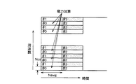
次に、スクランブルコードの相関検出方法について説明する。ただし、サブキャリア周波数は#1〜#NのN個とする。図38に示す例(第10の実施の形態)は、Navg=6,Ncs=4,Nps=N/Ncsの場合の例である。サブキャリア毎に各シンボルの相関値を時間方向にNavgシンボル同相加算する。そして、サブキャリア毎の同相加算値を、Ncsサブキャリアにわたり同相加算する。続いて、Ncsサブキャリア毎の同相加算値を周波数方向にNps個電力加算し、各スクランブルコードの相関値を求める。
【0137】
この例のようにNps=N/Ncsの場合には、Nサブキャリア×Navgシンボルを使用して1スクランブルコード分の相関値を検出することになる。
【0138】
図39に示す例(第11の実施の形態)は、Navg=6,Ncs=4,Nps=1の場合の例である。この場合、Nps=1であるため、Ncs個のサブキャリアの同相加算値が各スクランブルコードの相関値となり、Nサブキャリア×NavgシンボルでN/Ncs個のスクランブルコードの相関値を検出する。
【0139】
次に、図40に示す例(第12の実施の形態)は、Nps=(N/Ncs)/4の場合の例である。(N/Ncs)/Nps=4個のスクランブルコードの相関をNcsサブキャリア毎に交互に検出する。そして、Ncsサブキャリア毎の同相加算値を各コード毎に周波数方向にNps個電力加算することにより各スクランブルコードの相関値を検出することができる。
【0140】
この例のようにNps=(N/Ncs)/4の場合、Nサブキャリア×Navgシンボルを使用して4スクランブルコード分の相関値を検出する。
【0141】
さらに、図41に示す例(第13の実施の形態)は、Nps=(N/Ncs)/2の場合の例である。この場合、Nサブキャリア×Navgシンボルを使用して2スクランブルコード分の相関値を検出することができる。
【0142】
【発明の効果】
本発明によれば、スクランブルコードを用いたMC−CDMA方式において、高速かつ高精度な拡散符号同期が可能である。
【0143】
また本発明によれば、MC−CDMA方式を用いた移動通信システムにおいて、マルチセル環境下においてセル間に総送信電力にばらつきがあるような場合でも、複数候補を設けることにより最適セルのFFTタイミングを検出することができる。
【図面の簡単な説明】
【図1】従来例のMC−CDMA方式の移動通信システムにおける送信装置のブロック図。
【図2】上記の従来例におけるスクランブルコードパターンを示す図である。
【図3】本発明の第1の実施の形態の送信装置のブロック図である。
【図4】本発明の第1の実施の形態の送信装置における同期信号の構成を示す図である。
【図5】本発明の第1の実施の形態の送信装置における別の同期信号の構成を示す図である。
【図6】本発明の第1の実施の形態の送信装置におけるさらに別の同期信号の構成を示す図である。
【図7】本発明の第1の実施の形態の送信装置におけるさらに別の同期信号の構成を示図、及びその同期信号タイミングを示す図である。
【図8】本発明の第2の実施の形態の送信装置のブロック図である。
【図9】本発明の第2の実施の形態の送信装置における同期信号の構成を示す図である。
【図10】本発明の第3の実施の形態のMC−CDMA方式の受信装置のブロック図である。
【図11】本発明の第3の実施の形態の受信装置におけるスクランブルコード受信タイミング検出回路、スクランブルコード同定回路の詳しい構成を示すブロック図である。
【図12】本発明の第3の実施の形態の受信装置における復調回路の詳しい構成を示すブロック図である。
【図13】本発明の第3の実施の形態の受信装置によるマルチキャリア信号の受信方法を示すフローチャートである。
【図14】本発明の第4の実施の形態のMC−CDMA方式の受信装置のブロック図である。
【図15】本発明の第4の実施の形態の受信装置によるマルチキャリア信号の受信方法を示すフローチャートである。
【図16】本発明の第5の実施の形態のMC−CDMA方式の受信装置のブロック図である。
【図17】本発明の第5の実施の形態の受信装置によるマルチキャリア信号の受信方法を示すフローチャートである。
【図18】本発明の第6の実施の形態のMC−CDMA方式の受信装置のブロック図である。
【図19】本発明の第6の実施の形態の受信装置によるマルチキャリア信号の受信方法を示すフローチャートである。
【図20】本発明の第7の実施の形態のMC−CDMA方式の受信装置のブロック図である。
【図21】本発明の第7の実施の形態の受信装置によるマルチキャリア信号の受信方法を示すフローチャートである。
【図22】一般的なMC−CDMA方式における受信信号からFFTタイミングを検出する処理を示すフローチャートである。
【図23】図22に示すFFTタイミングの検出処理の説明図である。
【図24】検出されたFFTタイミングの相関系列図である。
【図25】本発明の第8の実施の形態のMC−CDMA方式の受信装置のブロック図である。
【図26】本発明の第8の実施の形態の受信装置による信号受信方法を示すフローチャートである。
【図27】本発明の第8の実施の形態の受信装置による信号受信方法により決定されたFFTタイミング候補を示す説明図である。
【図28】本発明の第7の実施の形態の受信装置による信号受信方法を示すフローチャートである。
【図29】本発明の第8の実施の形態の受信装置による別のFFTタイミング候補検出方法を示す説明図である。
【図30】本発明の第8の実施の形態の受信装置によるさらに別のFFTタイミング候補検出方法を示す説明図である。
【図31】本発明の第8の実施の形態の受信装置によるさらに別のFFTタイミング候補検出方法を示す説明図である。
【図32】本発明の第8の実施の形態の受信装置によるさらに別のFFTタイミング候補検出方法を示す説明図である。
【図33】本発明の第8の実施の形態の受信装置によるさらに別のFFTタイミング候補検出方法を示す説明図である。
【図34】本発明の第8の実施の形態の受信装置によるさらに別のFFTタイミング候補検出方法を示す説明図である。
【図35】本発明の第8の実施の形態の受信装置によるさらに別のFFTタイミング候補検出方法を示す説明図である。
【図36】本発明の第9の実施の形態のMC−CDMA方式の受信装置のブロック図である。
【図37】本発明の第7の実施の形態の受信装置による信号受信方法を示すフローチャートである。
【図38】本発明の第10の実施の形態の受信装置による長周期拡散符号の相関検出方法を示す図である。
【図39】本発明の第11の実施の形態の受信装置による長周期拡散符号の相関検出方法を示す図である。
【図40】本発明の第12の実施の形態の受信装置による長周期拡散符号の相関検出方法を示す図である。
【図41】本発明の第13の実施の形態の受信装置による長周期拡散符号の相関検出方法を示す図である。
【符号の説明】
10 送信装置
100 データチャネル生成回路
101 送信データ発生部
107 短周期拡散符号生成器
108 乗算器
109 第1の合成部
110 スクランブルコード生成器
111 乗算器
112 第2の合成部
113 IFFT回路
114 ガードインターバル挿入器
120 同期信号生成器
121 データ発生部
123 同期信号用拡散符号生成器
124 乗算器
125 直並列変換器
126 乗算器
199 アンテナ
20 受信装置
200 スクランブルコード受信タイミング検出回路
201 相関器
202 同期信号レプリカ生成器
203 相関値とタイミングのメモリ
204 タイミング検出回路
205 メモリ
207 加算器
208 ガードインターバル除去回路
209 FFT回路
210 スクランブルコード同定回路
211 スクランブルコードレプリカ生成器
212 相関器
213 加算器
214 相関値とコード番号のメモリ
215 スクランブルコード検出回路
2010 同期信号相関検出回路
2012 相関器
2013 同期信号レプリカ生成器
2014 FFTタイミング設定回路
2015 ガードインターバル除去回路
2016 FFT回路
230 スクランブルコード相関検出回路
240 スクランブルコード及びスクランブルコード受信タイミング検出回路
250 FFTタイミング検出回路
251 遅延回路
252 乗算器
253 積分器
254 相関値とタイミングのメモリ
255 タイミング検出回路
256 メモリ
300 復調回路
301 スクランブルコード生成器
302 FFTタイミング検出部
303 ガードインターバル除去回路
304 FFT回路
305 チャネル推定部
309 シートコード生成器
310 加算器
312 データ復調部
313 復号器[0001]
BACKGROUND OF THE INVENTION
The present invention relates to a transmission technique and a reception technique in a mobile communication system for performing spreading code synchronization on the receiving side in a multicarrier CDMA system using a long-period spreading code (scramble code).
[0002]
[Prior art]
In the following description, the “scramble code” is a “long-period spreading code” in the claims.
[0003]
In a multicarrier transmission scheme such as a multicarrier code division multiple access (MC-CDMA) scheme or an OFDM (Orthogonal Frequency Division Multiplexing) modulation scheme, an information signal is modulated by a plurality of subcarriers on the transmission side, and multipath A guard interval is inserted into the transmission signal for the purpose of reducing waveform distortion due to the delayed wave.
[0004]
FIG. 1 shows a configuration of a conventional MC-
[0005]
The combining
[0006]
The inverse Fourier
[0007]
The mobile station on the receiving side receives the radio multicarrier signal transmitted from the transmitting
[0008]
As a method for detecting the FFT timing in the multicarrier transmission method using the OFDM modulation method, there is known a method for detecting the FFT timing by correlating the guard interval portion inserted for each symbol (“multicarrier”). "Symbol synchronization and frequency offset simultaneous estimation method of modulated signal", Mori, Okada, Hara, Komaki, Morinaga, IEICE Technical Report RCS95-70, pp. 9-16, 1995-09). Also, a method is known in which the same signal is transmitted twice as a timing detection signal, and the FFT timing is detected by taking a correlation between two symbols on the receiving side (“OFDM modulation scheme for high-speed wireless LAN”). , Onizawa, Mizoguchi, Kumagai, Takanashi, Morikura, IEICE Technical Report RCS97-210, pp.137-142, 1998-01).
[0009]
In the MC-CDMA system, a communication person is identified by a short-period spreading code assigned to each communication person. For this reason, a plurality of communicators can simultaneously communicate using the same frequency band.
[0010]
[Problems to be solved by the invention]
When the above-described MC-CDMA system is used for mobile communication, it is necessary to use a scramble code in order to identify a base station. For this reason, a receiver for the MC-CDMA system must be able to identify the scramble code along with the detection of the FFT timing. In order to make this possible, the mobile station side needs to detect the correlation for all the scramble codes prepared in the system and detect the scramble code multiplied by the signal of the base station to be connected. is there. Considering flexible scramble code allocation, the number of scramble codes prepared in the system is about several hundreds. If it is going to cope with this, when a mobile station starts communication, it will take a long time to detect a scramble code. However, to date, research on MC-CDMA has been mainly related to link level evaluation and nothing related to identification of scramble codes.
[0011]
The present invention has been made to solve such a problem, and the object of the present invention is to provide a MC-CDMA system using a scramble code for identifying each of a plurality of base stations in the receiving station side. Is to provide a transmission technique and a reception technique in a mobile communication system that can detect a spread code at high speed and with high accuracy.
[0012]
The present invention also provides a signal reception technique capable of detecting the FFT timing of the optimum cell by providing a plurality of candidates as optimum base stations on the receiving side in the MC-CDMA mobile communication system. Objective.
[0013]
[Means for Solving the Problems]
In order to achieve the above object, the first feature of the present invention is that a short period spreading code product unit that multiplies each of a plurality of transmission data sequences by a plurality of short period spreading codes, and the short period spreading code multiplication. A long-period spread code product unit that multiplies a plurality of transmission-use data sequences multiplied by a short-period spread code output from the product unit, and a synchronization signal for the synchronization signal data. The transmission data obtained by multiplying the synchronization signal generating unit that multiplies and outputs the spreading code for use, and the short cycle spreading code and the long cycle spreading code that are output from the long cycle spreading code product unit. Each sequence is transmitted using a plurality of subcarriers, and a synchronization signal obtained by multiplying the synchronization signal data output from the synchronization signal generation unit with only a synchronization signal spreading code is transmitted as one or more subcarriers. Send using A transmitting device in a mobile communication system of MC-CDMA system comprising a signal processing unit.
[0014]
The second feature of the present invention is that a data sequence obtained by multiplying a short-period spreading code and a long-period spreading code is transmitted using a plurality of subcarriers, and is multiplied only by a synchronization signal spreading code. The transmission method in the mobile communication system is characterized by transmitting the synchronized signal using one or a plurality of subcarriers.
[0015]
A third feature of the present invention is that a data sequence obtained by multiplying a short-period spreading code and any one long-period spreading code included in the long-period spreading code group is transmitted using a plurality of subcarriers. A signal receiving unit for receiving a multicarrier signal including a synchronization signal obtained by multiplying only one or a plurality of subcarriers by a synchronization signal spreading code, in a MC-CDMA mobile communication system, A correlator for obtaining a correlation value between the multicarrier signal received by the signal receiving unit and a synchronization signal replica, and an FFT timing and a reception timing of the long-period spread code according to the correlation value obtained by the correlator And a timing detection unit for detecting.
[0016]
A fourth feature of the present invention is that a data series obtained by multiplying a short-period spreading code and any one long-period spreading code included in a long-period spreading code group is transmitted using a plurality of subcarriers. A signal receiving unit for receiving a multicarrier signal including a synchronization signal obtained by multiplying only one or a plurality of subcarriers by a synchronization signal spreading code, in a MC-CDMA mobile communication system, A first correlator for obtaining a correlation value between the multicarrier signal received by the signal receiving unit and a synchronization signal replica, and an FFT timing and the length according to the correlation value obtained by the first correlator A timing detector that detects the reception timing of the periodic spread code, and performs FFT according to the FFT timing detected by the timing detector, A plurality of subcarrier components separated by the FFT circuit according to the reception timing of the long-period spreading code detected by the timing detector, and the long-period spreading code group A second correlator for obtaining a correlation value between a code sequence obtained by multiplying each long-period spreading code and the short-period spreading code included in the second correlator, and the correlation value obtained by the second correlator And a code detection unit for detecting a long-period spread code for spreading the multicarrier signal, a reception timing of the long-cycle spread code detected by the timing detection unit, and the long-period spread detected by the code detection unit And a demodulation circuit that demodulates the data series from the multicarrier signal received by the signal reception unit using a code.
[0017]
A fifth feature of the present invention is that a data series obtained by multiplying a short-period spreading code and any one long-period spreading code included in a long-period spreading code group is transmitted using a plurality of subcarriers. A signal receiving unit for receiving a multicarrier signal including a synchronization signal obtained by multiplying only one or a plurality of subcarriers by a synchronization signal spreading code, in a MC-CDMA mobile communication system, A subcarrier separation unit that separates the multicarrier signal received by the signal reception unit into a plurality of subcarrier components, and a subcarrier component that includes the synchronization signal among the plurality of subcarrier components separated by the subcarrier separation unit A correlator for obtaining a correlation value between a carrier component and a synchronization signal replica, and detecting a reception timing of the long-period spread code according to the correlation value obtained by the correlator. Is obtained and a timing detection unit that.
[0018]
A sixth feature of the present invention is that a data sequence obtained by multiplying a short-period spreading code and any one long-period spreading code included in the long-period spreading code group is transmitted using a plurality of subcarriers. A signal receiving unit for receiving a multicarrier signal including a synchronization signal obtained by multiplying only one or a plurality of subcarriers by a synchronization signal spreading code, in a MC-CDMA mobile communication system, The multicarrier signal received by the signal receiving unit is subjected to FFT according to a plurality of FFT timings and separated into a plurality of subcarrier components, and the plurality of subcarriers separated by the subcarrier separating unit Among the carrier components, a correlator for obtaining a correlation value between a subcarrier component included in the synchronization signal and the synchronization signal replica, and a correlation value obtained by the correlator. Te, in which a timing detector for detecting the reception timing and FFT timing of the long period spreading code.
[0019]
A seventh feature of the present invention is that a data sequence obtained by multiplying a short-period spreading code and any one long-period spreading code included in a long-period spreading code group is transmitted using a plurality of subcarriers. A signal receiving unit for receiving a multicarrier signal including a synchronization signal obtained by multiplying only one or a plurality of subcarriers by a synchronization signal spreading code, in a MC-CDMA mobile communication system, A subcarrier separation unit that separates the multicarrier signal received by the signal reception unit into a plurality of subcarrier components, and a subcarrier component that includes the synchronization signal among the plurality of subcarrier components separated by the subcarrier separation unit A first correlator for obtaining a correlation value between a carrier component and a synchronization signal replica; and a receiver for the long-period spreading code according to the correlation value obtained by the first correlator. A timing detection unit that detects a ming, a plurality of subcarrier components separated by the subcarrier separation unit according to a reception timing of the long period spreading code detected by the timing detection unit, and the long period spreading code group A second correlator for obtaining a correlation value between a code sequence obtained by multiplying each of the long-period spreading code and the short-period spreading code, and a correlation value obtained by the second correlator. Accordingly, a code detection unit that detects a long-period spreading code that spreads the multicarrier signal, a reception timing of the long-period spreading code detected by the timing detection unit, and the long-period spreading code detected by the code detection unit And a demodulating circuit for demodulating the data series from the multicarrier signal received by the signal receiving unit.
[0020]
The eighth feature of the present invention is that a data sequence in which a short-period spreading code and any one long-period spreading code included in a long-period spreading code group are multiply multiplied is transmitted using a plurality of subcarriers. A signal receiving unit for receiving a multicarrier signal including a synchronization signal obtained by multiplying only one or a plurality of subcarriers by a synchronization signal spreading code, in a MC-CDMA mobile communication system, The multicarrier signal received by the signal receiving unit is subjected to FFT according to a plurality of FFT timings and separated into a plurality of subcarrier components, and the plurality of subcarriers separated by the subcarrier separating unit Of the carrier components, a first correlator that obtains a correlation value between a subcarrier component included in the synchronization signal and a synchronization signal replica, and the first correlator obtains the correlation value. According to the correlation value, a timing detection unit that detects the reception timing and FFT timing of the long-period spreading code, and performs FFT according to the FFT timing detected by the timing detection unit, the multicarrier signal The FFT circuit that separates into subcarrier components, and a plurality of subcarrier components separated by the FFT circuit according to the reception timing of the long period spreading code detected by the timing detection unit, and included in the long period spreading code group A second correlator that obtains a correlation value between a code sequence obtained by multiplying each long-period spreading code and the short-period spreading code, and the correlation value obtained by the second correlator A code detection unit for detecting a long-period spreading code for spreading the multicarrier signal, and reception of the long-period spreading code detected by the timing detection unit Using said long period spreading code timing and the code detecting section detects, is from the multi-carrier signal by the signal receiving unit receives those with a demodulation circuit for demodulating the data sequence.
[0021]
A ninth feature of the present invention is that a data series obtained by multiplying a short-period spreading code and any one long-period spreading code included in the long-period spreading code group is transmitted using a plurality of subcarriers. A receiving apparatus in an MC-CDMA mobile communication system that receives a multicarrier signal including a synchronization signal obtained by multiplying only one or a plurality of subcarriers with a synchronization signal spreading code. signal A receiving unit; a subcarrier separating unit that performs FFT on the multicarrier signal received by the signal receiving unit according to each of a plurality of FFT timings to separate a plurality of sets of subcarrier components; and the subcarrier separation A first correlator for obtaining a correlation value between a subcarrier component including the synchronization signal and a synchronization signal replica among the plurality of subcarrier components separated by a unit, and the correlation value obtained by the correlator A timing detection unit that detects a plurality of reception timing candidates of the long-period spreading code, and a plurality of sets of the plurality of sets according to the reception timing of the plurality of long-period spreading codes detected by the timing detection unit, respectively. A code obtained by multiplying a subcarrier component, each long-period spreading code included in the long-period spreading code group, and the short-period spreading code. A second correlator for obtaining a correlation value with a sequence, and a plurality of long-period spreading code candidates for spreading the multicarrier signal according to each of the plurality of correlation values obtained by the second correlator A candidate code detection unit, a plurality of reception timing candidates detected by the timing detection unit, and a plurality of long period spread code candidates detected by the code candidate detection unit, Using the timing and code detection unit for detecting the long-period spreading code, the reception timing of the long-period spreading code detected by the timing and code detection unit, and the long-period spreading code, the signal receiving unit has received And a demodulation circuit that demodulates the data series from the multicarrier signal.
[0022]
A tenth feature of the present invention is that a data sequence obtained by multiplying a short-period spreading code and any one long-period spreading code included in a long-period spreading code group is transmitted using a plurality of subcarriers. A receiving apparatus in an MC-CDMA mobile communication system that receives a multicarrier signal including a synchronization signal obtained by multiplying only one or a plurality of subcarriers with a synchronization signal spreading code. signal An FFT timing detection unit that detects a correlation between a reception unit, a guard interval portion of the multicarrier signal received by the signal reception unit and detects an FFT timing, and an FFT at the FFT timing detected by the FFT timing detection unit A correlation value between the subcarrier component including the synchronization signal and the synchronization signal replica among the plurality of subcarrier components separated by the subcarrier separation unit. A correlator to be obtained; and a timing detector for detecting a reception timing of the long-period spread code according to a correlation value obtained by the correlator.
[0023]
An eleventh feature of the present invention is that a data sequence obtained by multiplying a short-period spreading code and any one long-period spreading code included in the long-period spreading code group is transmitted using a plurality of subcarriers. A receiving apparatus in an MC-CDMA mobile communication system that receives a multicarrier signal including a synchronization signal obtained by multiplying only one or a plurality of subcarriers with a synchronization signal spreading code. signal A receiving unit; an FFT timing detecting unit for detecting an FFT timing based on a correlation characteristic of a guard interval included in the multicarrier signal received by the signal receiving unit; and the FFT timing detected by the FFT timing detecting unit. A subcarrier separation unit that performs FFT in order to separate a plurality of subcarrier components, and among the plurality of subcarrier components separated by the subcarrier separation unit, a subcarrier component including the synchronization signal and a synchronization signal replica A first correlator for obtaining a correlation value, a timing detection unit for detecting a reception timing of the long-period spread code according to the correlation value obtained by the first correlator, and the timing detected by the timing detection unit The subcarrier separated by the subcarrier separation unit according to the reception timing of the long-period spreading code. A second correlator for obtaining a correlation value between a component and a code sequence obtained by multiplying each long-period spreading code and the short-period spreading code included in the long-period spreading code group; A code detection unit that detects a long-period spreading code that spreads the multicarrier signal according to the correlation value obtained by the correlator, and a reception timing of the long-period spreading code detected by the timing detection unit and the code A demodulation circuit that demodulates the data series from the multicarrier signal received by the signal reception unit using the long-period spreading code detected by the detection unit;
[0024]
A twelfth feature of the present invention is that a data series obtained by multiplying a short-period spreading code and any one long-period spreading code included in a long-period spreading code group is transmitted using a plurality of subcarriers. Receiving a reception signal including a plurality of subcarriers having a synchronization signal obtained by multiplying one or a plurality of subcarriers by only a synchronization signal spreading code; A correlation output step for outputting a correlation value between the received signal received in step and the synchronization signal replica, and an FFT timing and a reception timing of the long-period spread code according to the correlation value output in the correlation output step And a timing detection step for detecting.
[0025]
In the reception method in the mobile communication system described above, further, a separation step of performing FFT according to the FFT timing detected in the timing detection step and separating the received signal into a plurality of subcarrier components, and the timing detection Depending on the reception timing of the long-period spreading code detected in the step, the subcarrier component, each long-period spreading code included in the long-period spreading code group, and the short-period spreading code are multiply multiplied A correlation detection step of outputting a correlation detection value with the code sequence that has been multiplied; and a code detection step of detecting a long-period spread code that spreads the received signal in accordance with the correlation detection value output from the correlation detection step. It can have.
[0026]
A thirteenth feature of the present invention is that a data sequence obtained by multiplying a short-period spreading code and any one long-period spreading code included in a long-period spreading code group is transmitted using a plurality of subcarriers. Receiving a reception signal including a plurality of subcarriers having a synchronization signal obtained by multiplying one or a plurality of subcarriers by only a synchronization signal spreading code; A separation step of separating the received signal received in step into a plurality of subcarrier components, and a subcarrier component and a synchronization signal included in the synchronization signal among the plurality of subcarrier components separated in the separation step A correlation output step of outputting a correlation value with the replica, and a reception type of the long-period spreading code according to the correlation value output at the correlation output step Those having a timing detection step of detecting a ring.
[0027]
In the reception method in the mobile communication system, the separation step performs FFT according to a plurality of FFT timings, and the timing detection step uses the correlation values output in the correlation output step for all the FFT timings. In response, the target FFT timing and the reception timing of the long-period spreading code are detected, and further, the FFT is performed according to the FFT timing detected in the timing detection step, and the received signal is converted into a plurality of subcarrier components. And the subcarrier component, each long-period spreading code included in the long-period spreading code group, and the long-period spreading code according to the reception timing of the long-period spreading code detected in the timing detection step. Correlation detection value with a code sequence obtained by multiplying a short period spread code A correlation detecting step of force, according to the correlation detection value outputted from said correlation detecting step, can be made and a code detection step of detecting a long period spreading code for spreading the received signal.
[0028]
A fourteenth feature of the present invention is that a data sequence obtained by multiplying a short-period spreading code and any one long-period spreading code included in a long-period spreading code group is transmitted using a plurality of subcarriers. Receiving a reception signal including the plurality of subcarriers having a synchronization signal obtained by multiplying one or a plurality of subcarriers by only a synchronization signal spreading code; and The received signal received in step is subjected to FFT according to a plurality of FFT timings and separated into a plurality of subcarrier components, and among the plurality of subcarrier components separated in the separation step, A correlation output step for outputting a correlation value between the subcarrier component included in the synchronization signal and the synchronization signal replica, and output in the correlation output step. A timing detection step for detecting the reception timing of the long-period spreading code according to the correlation value, and the subcarrier component and the long-time according to the reception timing of the long-period spreading code detected at the timing detection step Correlation detection step for outputting a correlation detection value of a code sequence obtained by multiplying each long-period spreading code and the short-period spreading code included in the period spreading code group, and for all the FFT timings, A code detection step for detecting the FFT timing, the reception timing of the long-period spreading code, and the long-period spreading code for spreading the received signal according to the correlation detection value output from the correlation detection step It is.
[0029]
A fifteenth feature of the present invention is that a data sequence in which a short-period spreading code and any one long-period spreading code included in a long-period spreading code group are multiply multiplied is transmitted using a plurality of subcarriers. In the receiving method in the mobile communication system, the FFT timing detection step of detecting the correlation of the guard interval portion of the received signal and detecting the FFT timing, and the FFT timing obtained in the FFT timing detection step, perform FFT, and And a correlation output step of outputting a correlation value between a subcarrier component included in the synchronization signal and a synchronization signal replica among the plurality of subcarrier components separated in the separation step. And a reception type of the long-period spreading code according to the correlation value output in the correlation output step. Those having a timing detection step of detecting a ring.
[0030]
In the reception method in the mobile communication system, the subcarrier component and each of the lengths included in the long-period spreading code group according to the reception timing of the long-period spreading code detected in the timing detection step. A correlation detection step of outputting a correlation detection value of a code sequence obtained by multiplying a cycle spreading code and the short cycle spreading code, and the received signal according to the correlation detection value output from the correlation detection step And a code detection step of detecting a long-period spreading code for spreading the data.
[0031]
A sixteenth feature of the present invention is that a data sequence obtained by multiplying a short-period spreading code and any one long-period spreading code included in a long-period spreading code group is transmitted using a plurality of subcarriers. A receiving apparatus in an MC-CDMA mobile communication system that receives a multicarrier signal including a synchronization signal obtained by multiplying only one or a plurality of subcarriers with a synchronization signal spreading code. signal A reception unit; and an FFT timing detection unit that detects a plurality of FFT timing candidates based on a correlation characteristic of a guard interval included in the multicarrier signal received by the signal reception unit, the FFT timing detection unit A multiplier that multiplies the multicarrier signal and a signal obtained by delaying the multicarrier signal by one symbol length, and an integrator that obtains a correlation value by integrating the multiplication value multiplied by the multiplier over a guard interval length. And a first memory for storing the correlation value obtained by the integrator and its timing, a second memory for storing a plurality of FFT timing candidates given in sequence, and the second memory. Searching each of the plurality of FFT timing candidates based on the plurality of FFT timing candidates and the stored value of the first memory A search range setting unit for setting a range, and first, a maximum correlation value and timing are selected from the stored values of the first memory, and stored in the second memory as the FFT
[0032]
In the reception apparatus in the MC-CDMA mobile communication system, the multicarrier signal is further subjected to FFT in each of the predetermined number of FFT timing candidates detected by the FFT timing detection unit, and a plurality of subcarriers are received. A correlation value between a subcarrier component including the synchronization signal and a synchronization signal replica among the plurality of subcarrier components separated by each of the plurality of subcarrier separation units separated into components and the plurality of subcarrier separation units is obtained. A plurality of first correlators, a plurality of timing detectors for detecting reception timing candidates of long-period spreading codes according to correlation values obtained by the plurality of first correlators, and the plurality of timing detections According to each reception timing candidate of the plurality of long-period spreading codes detected by each unit A plurality of second values for obtaining correlation values between the plurality of subcarrier components and a code sequence obtained by multiplying each of the long period spreading codes and the short period spreading codes included in the long period spreading code group. And a plurality of code candidate detections for detecting each of a plurality of long-period spread code candidates for spreading the multicarrier signal according to each of the plurality of correlation values obtained by each of the plurality of second correlators And a plurality of reception timing candidates detected by the plurality of timing detection units, and a plurality of long period spreading code candidates detected by the plurality of code candidate detection units, A timing and code detection unit for detecting the long-period spreading code, a reception timing of the long-period spreading code detected by the timing and code detection unit, and the long-period spreading code; Used, the data series from the multicarrier signal by the signal receiving unit receives can be provided with a demodulation circuit for demodulating.
[0033]
In the reception apparatus in the MC-CDMA mobile communication system, the multicarrier signal is further subjected to FFT in each of the predetermined number of FFT timing candidates detected by the FFT timing detection unit, and a plurality of subcarriers are received. A correlation value between a plurality of first FFT circuits that are separated into components and a subcarrier component that includes the synchronization signal and a synchronization signal replica among the plurality of subcarrier components separated by each of the plurality of first FFT circuits. A plurality of first correlators for obtaining the long-term spread code reception timing and FFT timing according to the correlation values obtained by the plurality of first correlators, and FFT is performed according to the FFT timing detected by the timing detector, and the multicarrier signal is transmitted. And a plurality of subcarrier components separated by the second FFT circuit in accordance with the reception timing of the long-period spreading code detected by the timing detection unit. A second correlator for obtaining a correlation value between a code sequence obtained by multiplying each long-period spreading code and the short-period spreading code included in the long-period spreading code group; and the second correlation A code detection unit that detects a long-period spreading code that spreads the multicarrier signal according to the correlation value obtained by the detector, a reception timing of the long-period spreading code detected by the timing detection unit, and the code detection unit And a demodulating circuit that demodulates the data sequence from the multicarrier signal received by the signal receiving unit using the long-period spreading code detected by.
[0034]
According to a seventeenth feature of the present invention, in a signal receiving method in a mobile communication system that transmits a code sequence using a plurality of subcarriers, the method includes a step of detecting a plurality of FFT timing candidates from a correlation characteristic of a guard interval. Is.
[0035]
According to an eighteenth feature of the present invention, in a signal receiving method in a mobile communication system that transmits a code sequence using a plurality of subcarriers, the received signal is multiplied by a signal obtained by delaying the received signal by one symbol length. A step of performing a moving average of the obtained multiplication values using the average interval as a guard interval length, a step of adding a correlation sequence of a plurality of correlation values obtained by the moving average in-phase for each guard interval insertion period, And detecting a plurality of FFT timing candidates from a correlation sequence having a length equal to the guard interval insertion period obtained by the addition.
[0036]
In the step of detecting a plurality of FFT timing candidates, the timing having the maximum correlation value is set as the first FFT timing candidate in the correlation sequence having a length equal to the guard interval insertion period obtained by the in-phase addition. Each of the second and subsequent FFT timing candidates, the timing having the maximum correlation value in the remaining correlation sequences obtained by excluding the peripheral W samples of each detected FFT timing candidate as an exclusion window is set to the next FFT. It is possible to have a step of detecting up to a predetermined number by repeating the method of timing candidates.
[0037]
According to a nineteenth feature of the present invention, in a signal receiving method in a mobile communication system that transmits a code sequence using a plurality of subcarriers, a step of detecting a plurality of FFT timing candidates from a correlation characteristic of a guard interval; Performing FFT on a plurality of FFT timing candidates and separating them into a plurality of subcarrier components, and outputting a correlation value between a subcarrier component including a synchronization signal and a synchronization signal replica among the plurality of separated subcarrier components A step of detecting one or more reception timing candidates for the long-period spreading code according to the output correlation value, and depending on the detected reception timing candidates for the one or more long-period spreading codes. Subcarrier component and each long-period spreading code and short-period spreading code included in the long-period spreading code group. A correlation detection value with the code sequence multiplied by the product, and for all detected FFT timing candidates, the FFT timing, the reception timing of the long-period spread code, and the reception signal are output according to the output correlation detection value. And a step of detecting a long-period spreading code to be spread.
[0038]
A twentieth feature of the present invention is that a data sequence obtained by multiplying a short-period spreading code and any one long-period spreading code included in a long-period spreading code group is transmitted using a plurality of subcarriers. In a signal reception method in a mobile communication system, a signal obtained by separating a received signal into subcarrier components by processing such as FFT, each long-period spreading code included in the long-period spreading code group, and the short-period spreading code, When a correlation detection value with a code sequence obtained by multiplying the two is multiplied, Navg symbols (Navg is an integer of 1 or more) are added in phase in the time direction to each subcarrier for each subcarrier. In-phase added values of Ncs subcarriers adjacent to each other in the frequency direction (Ncs is an integer satisfying 1 ≦ Ncs ≦ N, where N is the number of subcarriers), and the in-phase added value for each Ncs subcarrier is calculated in the frequency direction. Nps number (Nps is, 1 ≦ Nps ≦ N / Ncs becomes an integer) is used to detect the average correlation values by adding power.
[0039]
In the above-described signal reception method in the mobile communication system, when Nps <(N / Ncs), (N / Ncs) / Nps long-period spreading codes are alternately detected for each Ncs subcarrier in the frequency direction. Can be.
[0040]
DETAILED DESCRIPTION OF THE INVENTION
Hereinafter, embodiments of the present invention will be described in detail with reference to the drawings. FIG. 2 shows a frame structure of a transmission signal used in an MC-CDMA mobile communication system. A scramble code, which is a long-period spreading code, has a different pattern for each base station in both the frequency direction and the time direction.
[0041]
FIG. 3 shows the configuration of the MC-CDMA transmission device 10.1 used in the mobile communication system according to the first embodiment of the present invention. The transmission device 10.1 is provided for each base station that transmits a radio signal. The transmission device 10.1 includes a plurality of data channel generation circuits 100.1 to 100. x. In each of the data channel generation circuits 100, the transmission data sequence input from the transmission
[0042]
The
[0043]
An inverse Fourier transform device (IFFT) 113 converts N symbols into orthogonal multicarrier signals. The
[0044]
The synchronization signal is generated by the synchronization signal generator 120.1 as follows. The
[0045]
Next, a method of transmitting a multicarrier signal by the MC-transmitting device 10.1 in FIG. 3 will be described. FIG. 4A illustrates an example in which the synchronization signal generation unit 120.1 transmits the synchronization signal continuously in the time direction on a plurality of specific subcarriers. FIG. 5B shows an example in which the synchronization signal generation unit 120.1 continuously transmits the synchronization signal in a specific subcarrier in the time direction. These synchronization signals S1 are signals obtained by multiplying the data signal D1 output from the
[0046]
The second synthesizing unit 112.1 in the transmission device 10.1 continuously uses the synchronization signal S1 generated by the synchronization signal generation unit 120.1 on the time axis in the corresponding specific subcarrier among the N subcarriers. Multiplex. Then, the
[0047]
FIG. 5A also shows an example in which the synchronization signal is continuously transmitted in the time direction on one specific subcarrier. However, FIG. 5A shows an example in which the synchronization signal generator 120.1 generates the synchronization signal S2 in which the repetition time τ of one scramble code pattern is equal to the pattern length of the synchronization signal. The synchronization signal S2 indicates a data series having a specific pattern in the time direction. The specific pattern can be realized by a pattern of a scramble code for the synchronization signal. Therefore, in the receiving mobile station that receives the multicarrier signal transmitted by this transmission method, the reception timing of the multiplication start timing of the scramble code that is a long-period spreading code is detected by detecting the reception timing of the synchronization signal S2 from the received signal. Can be detected.
[0048]
FIG. 5B shows an example in which the length of the synchronization signal S3 is ½ of the repetition time τ of one scramble code pattern. Also in this case, the synchronization signal S3 is a sequence having a specific pattern in the time direction. Accordingly, the mobile station side can limit the reception timing of the scramble code multiplication start timing by detecting the transmission timing of the synchronization signal S3 from the received signal.
[0049]
The synchronization signal generated by the synchronization signal generation unit 120.1 is generated on the time axis in one or more specific subcarriers in the second synthesis unit 112.1 by the method shown in FIGS. Then, it is possible to multiplex in bursts. FIG. 6A shows an example in which the synchronization signal S4 is combined with a plurality of specific subcarriers and transmitted in bursts at the same timing. FIG. 6B shows an example in which the synchronization signal S4 is combined with one specific subcarrier and transmitted in bursts. FIG. 6C shows an example in which the synchronization signal S4 is combined with all subcarriers and transmitted in bursts at the same timing.
[0050]
FIGS. 7A and 7B are diagrams illustrating another method of transmitting the synchronization signal S5 used in the MC-CDMA transmission method. FIG. 7 (a) shows that the second synthesizing unit 112.1 changes the synchronization signal S5 having a constant pattern generated by the synchronization signal generating unit 120.1 to each of a plurality of specific subcarriers for each cycle of the scramble code. This is an example in which the synchronization signal S5 is multiplexed at the timing and transmitted in bursts. On the mobile station side that receives such a multicarrier signal, as shown in FIG. 7B, a plurality of subcarriers in which the synchronization signal S5 is transmitted from the reception signal and the reception timing of each synchronization signal S5 are determined. By detecting, the reception timing of the multiplication start timing of the scramble code can be detected.
[0051]
Next, the MC-CDMA transmission apparatus and transmission method according to the second embodiment of the present invention will be described. In the transmitting apparatus 10.2 shown in FIG. 8, elements that are the same as those of the transmitting apparatus shown in FIG. The feature of this embodiment is that the synchronization signal generation unit 120.1 includes a series-
[0052]
The second synthesis unit 112.2 multiplexes the synchronization signal generated from the synchronization signal generation unit 120.2 at a specific timing. This multiplexing method is shown in FIGS. 9 (a) and 9 (b).
[0053]
The transmission methods shown in FIGS. 9A and 9B are methods in which the synchronization signal S6 is transmitted in bursts in all subcarriers. FIG. 9A shows a case where the start time of one scramble code pattern and the transmission timing of the synchronization signal S6 are made simultaneously. Therefore, the mobile station side can detect the reception timing of the scramble code multiplication start timing by detecting the reception timing of the synchronization signal S6 from the reception signal. FIG. 9B shows a case where the synchronization signal S6 is transmitted twice within the repetition time τ of one scramble code pattern. In this case, the transmission timing interval of the synchronization signal S6 is ½ of the scramble code pattern repetition time τ. Therefore, on the mobile station side, the reception timing of the multiplication start timing of the scramble code can be limited by detecting the reception timing of the synchronization signal S6 from the reception signal.
[0054]
Next, the configuration of receiving apparatus 20.1 in the MC-CDMA mobile communication system according to the third embodiment will be described with reference to FIG. 10, FIG. 11, and FIG. The scramble code reception timing detection circuit 200.1 in the receiving apparatus 20.1 has the internal configuration shown in FIG. 11, and receives the multicarrier signal received by the
[0055]
A detailed configuration of the
[0056]
After detection of the scramble code reception timing by the scramble code reception timing detection circuit 200.1, the
[0057]
In the scramble code identification circuit 210.1, the scramble
[0058]
The scramble
Further, the detailed configuration of the
[0060]
On the other hand, the received multicarrier signal is also input to the FFT
[0061]
A method for receiving a multicarrier signal by the receiving apparatus 20.1 in the MC-CDMA mobile communication system having the above configuration will be described next. FIG. 13 is a flowchart showing signal reception processing by the receiving device 20.1 of FIG. First, a correlation between a reception signal including all subcarrier components before performing FFT and a synchronization signal replica is detected (S101). The FFT timing, that is, the symbol timing and the scramble code reception timing are simultaneously obtained based on the timing for obtaining the maximum correlation value (S102).
[0062]
Subsequently, FFT is performed at the detected FFT timing to separate the received signal into subcarrier components (S103). Further, at the reception timing of the detected scramble code, the correlation between the received signal separated into each subcarrier component after FFT and each scramble code is detected (S104), and the scramble code having the maximum correlation value is received. The signal is detected as a scramble code for spreading (S105).
[0063]
The
[0064]
Next, a receiving apparatus in the MC-CDMA mobile communication system according to the fourth embodiment of the present invention will be described with reference to FIG. The receiving device 20.2 of the fourth embodiment has the same functional block configuration as the receiving device 20.1 shown in FIG. 10, but the configuration of the scramble code reception timing detection circuit and the scramble code identification circuit is the same. Is different. This will be described.
[0065]
The scramble code reception timing detection circuit 200.2 receives a multicarrier signal, and a plurality of synchronization signal correlation detection circuits 2011.1 to 2010. Input to m. On the other hand, in the FFT
[0066]
The
[0067]
After detection of the scramble code reception timing by the scramble code reception timing detection circuit 200.2, the
[0068]
Next, a method of receiving a multicarrier signal by the receiving apparatus 20.2 having the above configuration will be described. FIG. 15 is a flowchart showing multicarrier signal reception processing by the receiving device 20.2 shown in FIGS. An FFT is performed at a certain FFT timing (S2011. 1), and a correlation between a subcarrier component transmitting a synchronization signal and a synchronization signal replica is detected for a signal after the FFT at a certain FFT timing (S2012. 1). This is performed at a plurality of FFT timings (S201.1 to S201.m). Of the correlation values detected at all the FFT timings, the reception timing of the scramble code is obtained at the timing at which the maximum correlation value is obtained. Further, the FFT timing is detected based on the FFT timing at which the maximum correlation value is detected (S202).
[0069]
Next, FFT is performed at the detected FFT timing (S203), and the received signal is separated into subcarrier components. At the reception timing of the detected scramble code, the correlation between the received signal separated into each subcarrier component after FFT and each scramble code is detected (S204), and the scramble code having the maximum correlation value is converted to the received signal. It is detected as a spreading scramble code (S205).
[0070]
Subsequently, the
[0071]
Next, a receiving apparatus according to a fifth embodiment of the present invention will be described with reference to FIGS. The receiving device 20.3 according to the fourth embodiment includes a scramble code reception timing detection circuit 200.3, a scramble code identification circuit 210.1, and a
[0072]
A scramble code reception timing detection circuit 200.3 receives a multicarrier signal and separates it into subcarrier components using a DFT circuit or the like 2011. Of the separated subcarrier components, only the subcarrier component on which the synchronization channel is multiplexed is input to the
[0073]
The configuration of the scramble identification circuit 210.1 is the same as that of FIG. The scramble
[0074]
A method for receiving a multicarrier signal by the receiving apparatus 20.3 in the MC-CDMA mobile communication system having the above configuration will be described next. FIG. 17 is a flowchart showing a multicarrier signal reception method by the reception device 20.3. First, a received signal is separated into subcarrier components using a DFT (Discrete Fourier Transform) circuit or the like (S301). Among the received signals separated into the subcarrier components, the correlation between the subcarrier component transmitting the synchronization signal and the synchronization signal is detected (S302), and the reception timing of the scramble code is determined by the timing to obtain the maximum correlation value. Obtain (S303).
[0075]
Next, at the reception timing of the detected scramble code, the correlation between the received signal separated into each subcarrier component and each scramble code is detected (S304), and the scramble code having the maximum correlation value is converted to the received signal. It is detected as a spreading scramble code (S305).
[0076]
The
[0077]
Next, a multicarrier signal receiver according to a sixth embodiment of the present invention will be described with reference to FIGS. 18 and 12. FIG. The receiving apparatus 20.4 includes m scramble code correlation detection circuits 230.1 to 230. m, an FFT
[0078]
Each scramble code correlation detection circuit 230. x inputs a multicarrier signal received by the
[0079]
The
[0080]
After the scramble code reception timing is detected, the scramble code identification circuit 210.2 sets the phase of the scramble
[0081]
The scramble code and scramble code reception
[0082]
A method for receiving a multicarrier signal by the receiving apparatus 20.4 in the MC-CDMA mobile communication system having the above configuration will be described next. FIG. 19 is a flowchart showing a multicarrier signal reception method by the reception device 20.4. The FFT is performed at a certain FFT timing (S4011.1), and the correlation between the subcarrier component transmitting the synchronization signal and the synchronization signal is detected for the signal after the FFT at a certain FFT timing (S4012.1). The timing for obtaining the maximum correlation value at each FFT timing is detected, and this is used as a scramble code reception timing candidate at the FFT timing (S4013.1). Then, at this scramble code reception timing, the correlation between the received signal separated into each subcarrier component and each scramble code is detected (S4014.1). This is performed at a plurality of FFT timings (S401.1 to S401.n).
[0083]
Subsequently, the scramble code having the maximum correlation value and its timing are detected from the scramble code correlation values detected at all FFT timings and the reception timing thereof (S402). Using the scramble code thus detected, the
[0084]
Next, a receiving apparatus used for the MC-CDMA transmission system according to the seventh embodiment of the present invention will be described with reference to FIG. 20 and FIG. The receiving apparatus 20.5 of this embodiment includes an FFT timing detection circuit 250.1, a
[0085]
The receiving device 20.5 inputs the multicarrier signal received by the
[0086]
After detecting the FFT timing, the
[0087]
Of the signals separated into the subcarrier components, only the subcarrier component on which the synchronization channel is multiplexed is input to each
[0088]
After detecting the scramble code reception timing, the scramble code identification circuit 210.1 specifies the scramble code number. The processing by the scramble code identification circuit 210.1 is the same as that in FIG. The scramble code number output from the scramble
[0089]
The
[0090]
Next, a method of receiving a multicarrier signal by the receiving apparatus 20.5 in the MC-CDMA mobile communication system having the above configuration will be described. FIG. 21 is a flowchart showing a multicarrier signal reception method by the reception device 20.5. First, a correlation between a reception signal including all subcarrier components before performing FFT and a signal obtained by delaying the reception signal by one symbol length (excluding the guard interval) is detected (S501). The FFT timing is obtained from the timing for obtaining the maximum correlation value (S502).
[0091]
Next, FFT is performed at the detected FFT timing, and the received signal is separated into subcarrier components (S503). Among the received signals separated into the subcarrier components, the correlation between the subcarrier component transmitting the synchronization signal and the synchronization signal is detected (S504), and the reception timing of the scramble code is determined by the timing for obtaining the maximum correlation value. Obtain (S505). Subsequently, a scramble code for spreading the received signal is detected by the same method as steps S304 and S305 in the flowchart of FIG.
[0092]
Using the scramble code thus obtained, the
[0093]
Next, a reception apparatus in the MC-CDMA mobile communication system according to the eighth embodiment of the present invention will be described. The MC-CDMA signal reception technique shown in the circuit of FIG. 20 and the flowchart of FIG. 21 detects one FFT timing from the timing at which the maximum correlation value is obtained using the correlation characteristics of the guard interval.
[0094]
However, in a MC-CDMA mobile communication system, in a situation where signals are simultaneously transmitted from a plurality of base stations and received simultaneously by one mobile station, if there is a variation in the total transmission power between the base stations, the mobile station A station may erroneously detect a signal of a base station having a large total transmission power as a normal signal, not a signal from an optimal base station having a small attenuation of a received signal. An example of the above problem is as follows.
[0095]
The flowchart of FIG. 22 shows the correlation detection processing procedure of the guard interval portion by the receiving apparatus of FIG. 20, and FIG. 23 shows the principle of the method. Here, the FFT timing is a timing at which the head of an information symbol not including a guard interval is received, and is a timing at which FFT processing is to be performed. Therefore, in the following description, all FFT timings are FFT timings. Further, it is assumed that 1 symbol length = X samples and guard interval length = Y samples.
[0096]
In the flowchart of FIG. 22 and the reception method shown in FIG. 23, a reception signal including all subcarrier components before FFT and a signal obtained by delaying the reception signal by one symbol (X sample) length are multiplied at each sample timing ( Step S1001). Then, the multiplication value for each sample timing is moving averaged for each sample, with each sample timing as the head of the average interval and the average interval length as the Y sample length (step S1002). A series of correlation values obtained by moving average is averaged a plurality of times by in-phase addition for each (X + Y) sample to obtain a correlation series of (X + Y) sample length (step S1003). FIG. 24 shows an example of this correlation sequence. Subsequently, the timing for obtaining the maximum correlation value in the correlation sequence of (X + Y) sample length as shown in FIG. 24 is detected as the FFT timing (step S1004).
[0097]
However, the magnitude of the correlation peak as in the correlation sequence shown in FIG. 24 depends not only on the attenuation amount of the received signal (path loss due to distance attenuation or shadowing) but also on the total transmission power of each base station. Therefore, when the above-described method is used in an MC-CDMA mobile communication system, the reception level per channel (minimum path loss is minimized) in a situation where the total transmission power of each base station varies in a multi-cell environment. There is a risk of erroneously detecting a base station with a high power of the transmitting communication channel instead of the optimal base station. For example, when the number of communication channels of the
[0098]
FIG. 25 shows a receiver in an MC-CDMA mobile communication system that solves this problem. 25 includes an FFT timing detection circuit 250.2 and scramble code correlation detection circuits 230.1 to 230. m, a scramble code and scramble code reception
[0099]
The FFT timing detection circuit 250.2 delays the received multicarrier signal by one symbol length (excluding GI) by the
[0100]
First, the
[0101]
The scramble code correlation detection circuits 230.1 to 230m are prepared for m FFT timing candidates detected by the FFT timing detection circuit 250.2. Each scramble code correlation detection circuit 230. The configuration of x (x = 1 to m) is the same as that shown in FIG. 18, and includes a
[0102]
Each scramble code correlation detection circuit 230. x inputs the multicarrier signal received by the
[0103]
The
[0104]
After detection of each scramble code reception timing candidate, the scramble code identification circuit 210.2 obtains a scramble code number and a correlation value corresponding to each scramble code reception timing candidate.
[0105]
The scramble code and scramble code reception
[0106]
The
[0107]
A method of detecting a predetermined number of FFT timing candidates from the received multicarrier signal by the FFT timing detection circuit 250.2 in the receiving apparatus 20.6 having the above configuration will be described with reference to the flowchart of FIG.
[0108]
The received multicarrier signal including all subcarrier components before FFT and the signal obtained by delaying the received multicarrier signal by one symbol (X sample) length are multiplied at each sample timing (step S1101). Then, the multiplication value for each sample timing is moving averaged for each sample, with each sample timing as the head of the average interval and the average interval length as the Y sample length (step S1102). A series of correlation values obtained by moving average is averaged a plurality of times by in-phase addition for each (X + Y) sample to obtain a correlation series of (X + Y) sample length (step S1103). The processes of S1101 to S1103 are the same as the processes of S1001 to S1003 in the flowchart of FIG.
[0109]
Subsequently, a plurality of FFT timing candidates are detected from the (X + Y) sample length correlation sequence as shown in FIG. 24 (steps S1104 to S1106). FIG. 27 shows a case where three FFT timing candidates are detected. This is detected as follows. First, let the timing at which the maximum correlation output is detected in the (X + Y) sample length correlation sequence be FFT
[0110]
By using the above method, even when the total transmission power of each base station varies in a multi-cell environment, it is possible to detect without missing a base station with a small total transmission power.
[0111]
Using the predetermined number m of FFT timing candidates detected in this way, next, a scramble code is identified by the flowchart shown in FIG. The process shown in FIG. 28 is an example when the number of scramble code reception timing candidates to be detected is equal to the number m of FFT window timing candidates.
[0112]
The process S1100 for detecting a plurality of m FFT timing candidates shows the entire process shown in the flowchart of FIG.
[0113]
Following this, FFT is performed on the detected plurality of FFT timing candidates, and the correlation between the subcarrier component transmitting the synchronization signal and the synchronization signal is detected for the signal after each FFT (steps S1201.1 and S1202). .1). The timing at which the maximum correlation value is detected in each FFT timing candidate is set as a scramble code reception timing candidate at that FFT timing, and the received signal and each scramble code separated into each subcarrier component in the scramble code reception timing candidate Is detected (steps S1203.1 and S1204.1). The processing of steps S1201.1 to S1204.1 is performed for all the plurality of m FFT timing candidates (S1200.1 to S1200.m).
[0114]
Next, among the scramble code correlation values detected in all FFT timing candidates, a scramble code that spreads the received signal, its reception timing, and FFT timing are detected from the scramble code having the maximum correlation value and its timing (S1300). ). That is, the FFT timing and scramble code reception timing are determined at the same time as the type of scramble code in step S1300.
[0115]
The method of detecting a plurality of m FFT timing candidates performed by the FFT timing detection circuit 250.2 in the receiving apparatus of FIG. 25 may be as shown in FIG. 29 or FIG. FIG. 29 shows a case where the
[0116]
FIG. 30 shows a case where the
[0117]
Next, another method for determining a plurality of FFT timing candidates will be described with reference to FIG. In the case of detecting three FFT timing candidates (m = 3), after detecting FFT
[0118]
Next, still another method for determining a plurality of FFT timing candidates will be described with reference to FIGS. 32 and 33. Also in this case, an example is shown in which three (m = 3) FFT timing candidates are detected. FIG. 32 shows a case where the window width is changed depending on the magnitude of the slope of the correlation sequence having the vertex at the FFT timing. When the slope of the correlation peak is steep, the exclusion window is narrowed, and when the slope is gentle, the exclusion window is widened. Set. That is, when the peak width is narrow, the width is narrowed as shown in the
[0119]
FIG. 33 shows an example in which an exclusion window is set while the correlation value continues to decrease as the distance from the detected FFT timing (the peak of the correlation peak) increases. In this case, after detecting FFT
[0120]
32 and 33, the exclusion window can be set adaptively even when the correlation peaks overlap or the peak width changes due to the influence of multipath.
[0121]
Next, another method for determining a plurality of FFT timing candidates will be described with reference to FIGS. 34 and 35. FIG. FIG. 34 shows the above FIG. FIG. This shows a method of detecting two FFT timing candidates by any one of the methods and adding eight new FFT timing candidates. First, two FFT
[0122]
FIG. 35 shows the above FIG. FIG. This shows a method of detecting two FFT timing candidates by any one of the methods and adding four new FFT timing candidates. First, two FFT
[0123]
According to the above method, even if the correlation peaks overlap and the timing is detected with a large shift from the ideal timing, or when it is detected with a shift due to the influence of noise or interference, the shift amount is kept small. It is possible to detect the FFT timing with higher accuracy.
[0124]
Note that, even if a plurality of m FFT timing candidates are detected by any of these methods, the process of detecting the scramble code number and the reception timing using the FFT timing candidates is performed by the process S1200 in FIG. According to S1300.
[0125]
Next, a receiving apparatus in the MC-CDMA mobile communication system according to the ninth embodiment of the present invention will be described with reference to FIG. The receiving apparatus 20.7 of this embodiment includes an FFT timing detection circuit 250.2 similar to that used in the receiving apparatus 20.6 of FIG. 25, the receiving
[0126]
The FFT timing detection circuit 250.2 detects a plurality of m FFT timing candidates from the received multicarrier signal by the same processing as in FIG.
[0127]
As in FIG. 14, the scramble code reception timing detection circuit 200.2 includes a
[0128]
The scramble code reception timing detection circuit 200.2 receives a multicarrier signal, and a plurality of m synchronization signal correlation detection circuits 2011.about.2010. Input to m. On the other hand, the FFT timing detection circuit 250.2 includes each synchronization signal correlation detection circuit 2010. FFT timing candidates are set for x (x = 1, 2,..., m).
[0129]
Each synchronization signal correlation detection circuit 2010. In x, the guard
[0130]
The
[0131]
After detection of the scramble code reception timing by the scramble code reception timing detection circuit 200.2, the
[0132]
The detection method of the scramble code number and timing by the receiving apparatus 20.7 having the above configuration is based on the flowchart of FIG. First, the FFT timing detection circuit 250.2 detects a predetermined number m of FFT timing candidates from the received multicarrier signal (S1100). This process is performed according to the flowchart of FIG. 26 as in the eighth embodiment. The detection of a plurality of FFT timing candidates may be performed by any of the methods shown in FIGS.
[0133]
Next, FFT is performed on a plurality of detected FFT timing candidates, and the correlation between the subcarrier component transmitting the synchronization signal and the synchronization signal is detected for the signal after each FFT (S1401.1, S1402.1). . This is performed for all FFT timing candidates (S1400.1 to S1400.m).
[0134]
Subsequently, of the correlation values in all FFT timing candidates, the timing at which the maximum correlation value is detected and the FFT timing at that time are used as the reception timing of the scramble code for spreading the reception signal and the FFT timing of the reception signal ( Step S1500). Next, at the detected scramble code reception timing, the correlation between the received signal separated into each subcarrier component and each scramble code is detected (step S1600). Then, a scramble code for spreading the received signal is detected from the scramble code having the maximum correlation value (step S1700).
[0135]
In the method shown in the flowchart of FIG. 37, the FFT timing and the reception timing of the scramble code are determined in step S1500 before the scramble code type is detected.
[0136]
Next, a method for detecting correlation of scramble codes will be described. However, N subcarrier frequencies are assumed to be # 1 to #N. The example (tenth embodiment) shown in FIG. 38 is an example in the case of Navg = 6, Ncs = 4, Nps = N / Ncs. The correlation value of each symbol is added in the Navg symbol in-phase in the time direction for each subcarrier. Then, the in-phase addition value for each subcarrier is in-phase added over Ncs subcarriers. Subsequently, Nps powers are added to the in-phase added value for each Ncs subcarrier in the frequency direction to obtain a correlation value of each scramble code.
[0137]
When Nps = N / Ncs as in this example, correlation values for one scramble code are detected using N subcarriers × Navg symbols.
[0138]
The example (eleventh embodiment) shown in FIG. 39 is an example in the case of Navg = 6, Ncs = 4, and Nps = 1. In this case, since Nps = 1, the in-phase addition value of Ncs subcarriers becomes the correlation value of each scramble code, and the correlation value of N / Ncs scramble codes is detected by N subcarriers × Navg symbols.
[0139]
Next, the example shown in FIG. 40 (the twelfth embodiment) is an example in the case of Nps = (N / Ncs) / 4. Correlation of (N / Ncs) / Nps = 4 scramble codes is detected alternately for each Ncs subcarrier. Then, the correlation value of each scramble code can be detected by adding Nps powers of the in-phase addition value for each Ncs subcarrier in the frequency direction for each code.
[0140]
When Nps = (N / Ncs) / 4 as in this example, correlation values for four scramble codes are detected using N subcarriers × Navg symbols.
[0141]
Furthermore, the example (13th Embodiment) shown in FIG. 41 is an example in the case of Nps = (N / Ncs) / 2. In this case, correlation values for two scramble codes can be detected using N subcarriers × Navg symbols.
[0142]
【The invention's effect】
According to the present invention, high-speed and high-accuracy spread code synchronization is possible in the MC-CDMA system using a scramble code.
[0143]
The present invention In Therefore, in a mobile communication system using the MC-CDMA system, it is possible to detect the FFT timing of the optimum cell by providing a plurality of candidates even when the total transmission power varies among cells in a multi-cell environment. it can.
[Brief description of the drawings]
FIG. 1 is a block diagram of a transmission apparatus in a conventional MC-CDMA mobile communication system.
FIG. 2 is a diagram showing a scramble code pattern in the conventional example.
FIG. 3 is a block diagram of a transmission apparatus according to the first embodiment of this invention.
FIG. 4 is a diagram illustrating a configuration of a synchronization signal in the transmission apparatus according to the first embodiment of the present invention.
FIG. 5 is a diagram illustrating a configuration of another synchronization signal in the transmission apparatus according to the first embodiment of the present invention.
FIG. 6 is a diagram illustrating a configuration of still another synchronization signal in the transmission apparatus according to the first embodiment of the present invention.
FIG. 7 is a diagram illustrating a configuration of still another synchronization signal in the transmission apparatus according to the first embodiment of the present invention, and a diagram illustrating a synchronization signal timing thereof;
FIG. 8 is a block diagram of a transmission apparatus according to a second embodiment of this invention.
FIG. 9 is a diagram illustrating a configuration of a synchronization signal in the transmission apparatus according to the second embodiment of the present invention.
FIG. 10 is a block diagram of an MC-CDMA receiving apparatus according to a third embodiment of this invention.
FIG. 11 is a block diagram showing a detailed configuration of a scramble code reception timing detection circuit and a scramble code identification circuit in the reception apparatus according to the third embodiment of the present invention.
FIG. 12 is a block diagram showing a detailed configuration of a demodulation circuit in the receiving apparatus according to the third embodiment of the present invention.
FIG. 13 is a flowchart illustrating a multicarrier signal reception method by the reception apparatus according to the third embodiment of the present invention.
FIG. 14 is a block diagram of an MC-CDMA receiving apparatus according to a fourth embodiment of this invention.
FIG. 15 is a flowchart illustrating a multicarrier signal reception method by the reception apparatus according to the fourth embodiment of the present invention.
FIG. 16 is a block diagram of an MC-CDMA reception device according to a fifth embodiment of this invention;
FIG. 17 is a flowchart illustrating a multicarrier signal reception method by the reception apparatus according to the fifth embodiment of the present invention;
FIG. 18 is a block diagram of an MC-CDMA reception device according to a sixth embodiment of this invention;
FIG. 19 is a flowchart illustrating a multicarrier signal reception method by the reception apparatus according to the sixth embodiment of the present invention.
FIG. 20 is a block diagram of an MC-CDMA receiving apparatus according to a seventh embodiment of the present invention.
FIG. 21 is a flowchart illustrating a multicarrier signal reception method by the reception apparatus according to the seventh embodiment of the present invention.
FIG. 22 is a flowchart showing processing for detecting FFT timing from a received signal in a general MC-CDMA system.
FIG. 23 is an explanatory diagram of FFT timing detection processing shown in FIG. 22;
FIG. 24 is a correlation sequence diagram of detected FFT timings.
FIG. 25 is a block diagram of an MC-CDMA reception device according to an eighth embodiment of the present invention;
FIG. 26 is a flowchart illustrating a signal reception method by the reception device according to the eighth embodiment of the present invention.
FIG. 27 is an explanatory diagram illustrating FFT timing candidates determined by the signal reception method by the reception device according to the eighth embodiment of the present invention;
FIG. 28 is a flowchart illustrating a signal reception method by the reception device according to the seventh embodiment of the present invention.
FIG. 29 is an explanatory diagram showing another FFT timing candidate detection method by the reception device according to the eighth embodiment of the present invention;
FIG. 30 is an explanatory diagram showing another FFT timing candidate detection method by the reception device according to the eighth embodiment of the present invention;
FIG. 31 is an explanatory diagram showing still another FFT timing candidate detection method by the reception device according to the eighth embodiment of the present invention;
FIG. 32 is an explanatory diagram showing another FFT timing candidate detection method by the reception device according to the eighth embodiment of the present invention;
FIG. 33 is an explanatory diagram showing still another FFT timing candidate detection method by the reception device according to the eighth embodiment of the present invention;
FIG. 34 is an explanatory diagram showing still another FFT timing candidate detection method by the reception device according to the eighth embodiment of the present invention;
FIG. 35 is an explanatory diagram showing another FFT timing candidate detection method by the reception device according to the eighth embodiment of the present invention;
FIG. 36 is a block diagram of an MC-CDMA reception device according to a ninth embodiment of this invention;
FIG. 37 is a flowchart illustrating a signal reception method by the reception device according to the seventh embodiment of the present invention.
FIG. 38 is a diagram illustrating a correlation detection method for a long-period spread code by the reception device according to the tenth embodiment of the present invention.
FIG. 39 is a diagram illustrating a correlation detection method for a long-period spread code by the reception device according to the eleventh embodiment of the present invention.
FIG. 40 is a diagram illustrating a correlation detection method for a long-period spread code by the reception device according to the twelfth embodiment of the present invention.
FIG. 41 is a diagram illustrating a correlation detection method for a long-period spread code by the reception device according to the thirteenth embodiment of the present invention.
[Explanation of symbols]
10 Transmitter
100 data channel generation circuit
101 Transmission data generator
107 Short-period spreading code generator
108 multiplier
109 1st composition part
110 Scramble code generator
111 multiplier
112 Second synthesis unit
113 IFFT circuit
114 Guard interval inserter
120 synchronization signal generator
121 Data generator
123 Spreading Code Generator for Synchronization Signal
124 multiplier
125 series-parallel converter
126 multiplier
199 antenna
20 Receiver
200 Scramble code reception timing detection circuit
201 Correlator
202 Synchronization signal replica generator
203 Memory of correlation value and timing
204 Timing detection circuit
205 memory
207 Adder
208 Guard interval removal circuit
209 FFT circuit
210 Scramble code identification circuit
211 Scramble code replica generator
212 Correlator
213 Adder
214 Memory of correlation value and code number
215 Scramble code detection circuit
2010 Sync signal correlation detection circuit
2012 correlator
2013 Synchronous signal replica generator
2014 FFT timing setting circuit
2015 guard interval removal circuit
2016 FFT circuit
230 Scramble code correlation detection circuit
240 Scramble code and scramble code reception timing detection circuit
250 FFT timing detection circuit
251 delay circuit
252 multiplier
253 integrator
254 Correlation value and timing memory
255 Timing detection circuit
256 memory
300 Demodulator
301 Scramble code generator
302 FFT timing detector
303 Guard interval removal circuit
304 FFT circuit
305 Channel estimation unit
309 Sheet code generator
310 Adder
312 Data demodulator
313 Decoder
Claims (35)
前記短周期拡散符号乗積部から出力される短周期拡散符号の乗積された前記複数の送信用データ系列それぞれに共通する長周期拡散符号を乗積する長周期拡散符号乗積部と、
同期信号用データを発生する同期信号用データ発生部、同期信号用拡散符号を生成する同期信号用拡散符号生成部及び前記同期信号用データ発生部によって発生された同期信号用データに前記同期信号用拡散符号生成部によって発生された同期信号用拡散符号を乗積し、同期信号として出力する乗積部を有する同期信号生成部と、
前記長周期拡散符号乗積部から出力される短周期拡散符号と長周期拡散符号とが二重に乗積された前記送信用データ系列それぞれと前記同期信号生成部の出力する同期信号用データに同期信号用拡散符号のみが乗積された同期信号とを、当該同期信号が前記同期信号用拡散符号の符号系列のパターンにより前記長周期拡散符号の送信タイミングを表す態様で合成する送信信号合成部と、
前記送信信号合成手段にて合成された合成信号を1又は複数のサブキャリアを用いて送出する送信処理部とを備えて成るマルチキャリアCDMA方式の移動通信システムにおける送信装置。A short period spreading code product unit for multiplying each of a plurality of transmission data series by a plurality of short period spreading codes,
A long period spreading code product unit that multiplies a long period spreading code common to each of the plurality of transmission data sequences multiplied by the short period spreading code output from the short period spreading code product unit;
The synchronization signal data generating unit for generating the synchronization signal data, the synchronization signal spreading code generating unit for generating the synchronization signal spreading code, and the synchronization signal data generated by the synchronization signal data generating unit A synchronization signal generation unit having a multiplication unit that multiplies the synchronization signal spreading code generated by the spreading code generation unit and outputs the product as a synchronization signal;
Each of the transmission data series obtained by multiplying the short-period spreading code and the long-period spreading code output from the long-period spreading code product section and the synchronization signal data output from the synchronization signal generating section A transmission signal synthesizer that synthesizes a synchronization signal obtained by multiplying only the synchronization signal spreading code in such a manner that the synchronization signal represents the transmission timing of the long-period spreading code by the code sequence pattern of the synchronization signal spreading code. When,
A transmission apparatus in a multi-carrier CDMA mobile communication system, comprising: a transmission processing unit that transmits a combined signal combined by the transmission signal combining means using one or a plurality of subcarriers.
1または複数のサブキャリアに、同期信号用拡散符号のみが乗積された同期信号を含むマルチキャリア信号を受信する信号受信部と、
前記信号受信部が受信した前記マルチキャリア信号と、同期信号レプリカとの相関値を求める相関器と、
前記相関器が求めた前記相関値に応じて、FFTタイミングと前記長周期拡散符号の受信タイミングとを検出するタイミング検出部とを備えて成るマルチキャリアCDMA方式の移動通信システムにおける受信装置。A multi-carrier CDMA mobile communication system for transmitting a data sequence obtained by multiplying a short period spreading code and any one long period spreading code included in a long period spreading code group by using a plurality of subcarriers A receiving device in
A signal receiving unit that receives a multicarrier signal including a synchronization signal obtained by multiplying only one or a plurality of subcarriers by a synchronization signal spreading code;
A correlator for obtaining a correlation value between the multicarrier signal received by the signal receiving unit and a synchronization signal replica;
A receiving apparatus in a multi-carrier CDMA mobile communication system, comprising: a timing detector that detects an FFT timing and a reception timing of the long-period spread code according to the correlation value obtained by the correlator.
1または複数のサブキャリアに、同期信号用拡散符号のみが乗積された同期信号を含むマルチキャリア信号を受信する信号受信部と、
前記信号受信部が受信した前記マルチキャリア信号と、同期信号レプリカとの相関値を求める第1の相関器と、
前記第1の相関器が求めた前記相関値に応じて、FFTタイミングと前記長周期拡散符号の受信タイミングとを検出するタイミング検出部と、
前記タイミング検出部が検出した前記FFTタイミングに応じてFFTを行い、前記マルチキャリア信号を複数のサブキャリア成分に分離するFFT回路と、
前記タイミング検出部が検出した前記長周期拡散符号の受信タイミングに応じて、前記FFT回路が分離した前記複数のサブキャリア成分と、前記長周期拡散符号群に含まれる各々の長周期拡散符号と前記短周期拡散符号とを二重に乗積した符号系列との相関値を求める第2の相関器と、
前記第2の相関器が求めた前記相関値に応じて、前記マルチキャリア信号を拡散する長周期拡散符号を検出する符号検出部と、
前記タイミング検出部が検出した前記長周期拡散符号の受信タイミングと前記符号検出部が検出した前記長周期拡散符号とを用いて、前記信号受信部が受信した前記マルチキャリア信号から前記データ系列を復調する復調回路とを備えて成るマルチキャリアCDMA方式の移動通信システムにおける受信装置。A multi-carrier CDMA mobile communication system for transmitting a data sequence obtained by multiplying a short period spreading code and any one long period spreading code included in a long period spreading code group by using a plurality of subcarriers A receiving device in
A signal receiving unit that receives a multicarrier signal including a synchronization signal obtained by multiplying only one or a plurality of subcarriers by a synchronization signal spreading code;
A first correlator for obtaining a correlation value between the multicarrier signal received by the signal receiving unit and a synchronization signal replica;
A timing detector that detects FFT timing and the reception timing of the long-period spread code according to the correlation value obtained by the first correlator;
An FFT circuit that performs FFT according to the FFT timing detected by the timing detection unit and separates the multicarrier signal into a plurality of subcarrier components;
The plurality of subcarrier components separated by the FFT circuit according to the reception timing of the long-period spreading code detected by the timing detection unit, each long-period spreading code included in the long-period spreading code group, and the A second correlator for obtaining a correlation value with a code sequence obtained by multiplying a short-period spreading code by double multiplication;
A code detection unit for detecting a long-period spreading code for spreading the multicarrier signal according to the correlation value obtained by the second correlator;
The data sequence is demodulated from the multicarrier signal received by the signal receiving unit using the reception timing of the long period spreading code detected by the timing detecting unit and the long period spreading code detected by the code detecting unit. Receiving device in a multi-carrier CDMA mobile communication system.
1または複数のサブキャリアに、同期信号用拡散符号のみが乗積された同期信号を含むマルチキャリア信号を受信する信号受信部と、
前記信号受信部が受信した前記マルチキャリア信号を、複数のFFTタイミングに応じてFFTを行い、複数のサブキャリア成分に分離するサブキャリア分離部と、
前記サブキャリア分離部が分離した前記複数のサブキャリア成分のうち、前記同期信号に含まれるサブキャリア成分と同期信号レプリカとの相関値を求める相関器と、
前記相関器が求めた相関値に応じて、前記長周期拡散符号の受信タイミングとFFTタイミングとを検出するタイミング検出部とを備えて成るマルチキャリアCDMA方式の移動通信システムにおける受信装置。A multi-carrier CDMA mobile communication system for transmitting a data sequence obtained by multiplying a short period spreading code and any one long period spreading code included in a long period spreading code group by using a plurality of subcarriers A receiving device in
A signal receiving unit that receives a multicarrier signal including a synchronization signal obtained by multiplying only one or a plurality of subcarriers by a synchronization signal spreading code;
A subcarrier separation unit that performs FFT according to a plurality of FFT timings and separates the multicarrier signal received by the signal reception unit into a plurality of subcarrier components;
Of the plurality of subcarrier components separated by the subcarrier separation unit, a correlator for obtaining a correlation value between a subcarrier component included in the synchronization signal and a synchronization signal replica;
A receiving apparatus in a multi-carrier CDMA mobile communication system, comprising: a timing detection unit that detects reception timing and FFT timing of the long-period spread code according to a correlation value obtained by the correlator.
1または複数のサブキャリアに、同期信号用拡散符号のみが乗積された同期信号を含むマルチキャリア信号を受信する信号受信部と、
前記信号受信部が受信した前記マルチキャリア信号を、複数のFFTタイミングに応じてFFTを行い、複数のサブキャリア成分に分離するサブキャリア分離部と、
前記サブキャリア分離部が分離した前記複数のサブキャリア成分のうち、前記同期信号に含まれるサブキャリア成分と同期信号レプリカとの相関値を求める第1の相関器と、
前記第1の相関器が求めた相関値に応じて、前記長周期拡散符号の受信タイミングとFFTタイミングとを検出するタイミング検出部と、
前記タイミング検出部が検出した前記FFTタイミングに応じてFFTを行い、前記マルチキャリア信号を複数のサブキャリア成分に分離するFFT回路と、
前記タイミング検出部が検出した前記長周期拡散符号の受信タイミングに応じて、前記FFT回路が分離した複数のサブキャリア成分と、前記長周期拡散符号群に含まれる各々の長周期拡散符号と前記短周期拡散符号とを二重に乗積した符号系列との相関値を求める第2の相関器と、
前記第2の相関器が求めた前記相関値に応じて、前記マルチキャリア信号を拡散する長周期拡散符号を検出する符号検出部と、
前記タイミング検出部が検出した前記長周期拡散符号の受信タイミングと前記符号検出部が検出した前記長周期拡散符号とを用いて、前記信号受信部が受信した前記マルチキャリア信号から前記データ系列を復調する復調回路とを備えて成るマルチキャリアCDMA方式の移動通信システムにおける受信装置。A multi-carrier CDMA mobile communication system for transmitting a data sequence obtained by multiplying a short period spreading code and any one long period spreading code included in a long period spreading code group by using a plurality of subcarriers A receiving device in
A signal receiving unit that receives a multicarrier signal including a synchronization signal obtained by multiplying only one or a plurality of subcarriers by a synchronization signal spreading code;
A subcarrier separation unit that performs FFT according to a plurality of FFT timings and separates the multicarrier signal received by the signal reception unit into a plurality of subcarrier components;
A first correlator for obtaining a correlation value between a subcarrier component included in the synchronization signal and a synchronization signal replica among the plurality of subcarrier components separated by the subcarrier separation unit;
A timing detector that detects the reception timing and FFT timing of the long-period spread code according to the correlation value obtained by the first correlator;
An FFT circuit that performs FFT according to the FFT timing detected by the timing detection unit and separates the multicarrier signal into a plurality of subcarrier components;
A plurality of subcarrier components separated by the FFT circuit, each long-period spreading code included in the long-period spreading code group, and the short A second correlator for obtaining a correlation value with a code sequence obtained by multiplying the cyclic spreading code by a double product;
A code detection unit for detecting a long-period spreading code for spreading the multicarrier signal according to the correlation value obtained by the second correlator;
The data sequence is demodulated from the multicarrier signal received by the signal receiving unit using the reception timing of the long period spreading code detected by the timing detecting unit and the long period spreading code detected by the code detecting unit. Receiving device in a multi-carrier CDMA mobile communication system.
1または複数のサブキャリアに、同期信号用拡散符号のみが乗積された同期信号を含むマルチキャリア信号を受信する信号受信部と、
前記信号受信部が受信した前記マルチキャリア信号を、複数のサブキャリア成分に分離するサブキャリア分離部と、
前記サブキャリア分離部が分離した前記複数のサブキャリア成分のうち、前記同期信号を含むサブキャリア成分と同期信号レプリカとの相関値を求める相関器と、
前記相関器が求めた前記相関値に応じて、前記長周期拡散符号の受信タイミングを検出するタイミング検出部とを備えて成るマルチキャリアCDMA方式の移動通信システムにおける受信装置。A multi-carrier CDMA mobile communication system for transmitting a data sequence obtained by multiplying a short period spreading code and any one long period spreading code included in a long period spreading code group by using a plurality of subcarriers A receiving device in
A signal receiving unit that receives a multicarrier signal including a synchronization signal obtained by multiplying only one or a plurality of subcarriers by a synchronization signal spreading code;
A subcarrier separation unit that separates the multicarrier signal received by the signal reception unit into a plurality of subcarrier components;
Of the plurality of subcarrier components separated by the subcarrier separation unit, a correlator for obtaining a correlation value between a subcarrier component including the synchronization signal and a synchronization signal replica;
A receiving apparatus in a multi-carrier CDMA mobile communication system, comprising: a timing detection unit that detects reception timing of the long-period spread code according to the correlation value obtained by the correlator.
1または複数のサブキャリアに、同期信号用拡散符号のみが乗積された同期信号を含むマルチキャリア信号を受信する信号受信部と、
前記信号受信部が受信した前記マルチキャリア信号を、複数のサブキャリア成分に分離するサブキャリア分離部と、
前記サブキャリア分離部が分離した前記複数のサブキャリア成分のうち、前記同期信号を含むサブキャリア成分と同期信号レプリカとの相関値を求める第1の相関器と、
前記第1の相関器が求めた前記相関値に応じて、前記長周期拡散符号の受信タイミングを検出するタイミング検出部と、
前記タイミング検出部が検出した前記長周期拡散符号の受信タイミングに応じて、前記サブキャリア分離部が分離した前記複数のサブキャリア成分と、前記長周期拡散符号群に含まれる各々の長周期拡散符号と前記短周期拡散符号とを二重に乗積した符号系列との相関値を求める第2の相関器と、
前記第2の相関器が求めた相関値に応じて、前記マルチキャリア信号を拡散する長周期拡散符号を検出する符号検出部と、
前記タイミング検出部が検出した前記長周期拡散符号の受信タイミングと前記符号検出部が検出した前記長周期拡散符号とを用いて、前記信号受信部が受信した前記マルチキャリア信号から前記データ系列を復調する復調回路とを備えて成るマルチキャリアCDMA方式の移動通信システムにおける受信装置。A multi-carrier CDMA mobile communication system for transmitting a data sequence obtained by multiplying a short period spreading code and any one long period spreading code included in a long period spreading code group by using a plurality of subcarriers A receiving device in
A signal receiving unit that receives a multicarrier signal including a synchronization signal obtained by multiplying only one or a plurality of subcarriers by a synchronization signal spreading code;
A subcarrier separation unit that separates the multicarrier signal received by the signal reception unit into a plurality of subcarrier components;
A first correlator for obtaining a correlation value between a subcarrier component including the synchronization signal and a synchronization signal replica among the plurality of subcarrier components separated by the subcarrier separation unit;
A timing detector for detecting a reception timing of the long-period spread code according to the correlation value obtained by the first correlator;
The plurality of subcarrier components separated by the subcarrier separation unit according to the reception timing of the long period spreading code detected by the timing detection unit, and each long period spreading code included in the long period spreading code group And a second correlator for obtaining a correlation value between a code sequence obtained by multiplying the short period spread code and the short period spreading code;
A code detection unit for detecting a long-period spreading code for spreading the multicarrier signal according to the correlation value obtained by the second correlator;
The data sequence is demodulated from the multicarrier signal received by the signal receiving unit using the reception timing of the long period spreading code detected by the timing detecting unit and the long period spreading code detected by the code detecting unit. Receiving device in a multi-carrier CDMA mobile communication system.
1または複数のサブキャリアに、同期信号用拡散符号のみが乗積された同期信号を含むマルチキャリア信号を受信する信号受信部と、
前記信号受信部が受信した前記マルチキャリア信号を、複数のFFTタイミングそれぞれに応じてFFTを行い、複数のサブキャリア成分を1組とする複数組に分離するサブキャリア分離部と、
前記サブキャリア分離部が分離した前記複数のサブキャリア成分のうち前記同期信号を含むサブキャリア成分と同期信号レプリカとの相関値を前記複数組それぞれについて求める第1の相関器と、
前記第1の相関器が求めた複数個の前記相関値に応じて、前記長周期拡散符号の複数個の受信タイミング候補を検出するタイミング検出部と、
前記タイミング検出部が検出した前記複数の長周期拡散符号の受信タイミング候補それぞれに応じて、前記複数のサブキャリア成分と、前記長周期拡散符号群に含まれる各々の長周期拡散符号と前記短周期拡散符号とを二重に乗積した符号系列との相関値を前記複数組それぞれについて求める第2の相関器と、
前記第2の相関器が求めた前記複数の相関値それぞれに応じて、前記マルチキャリア信号を拡散する複数の長周期拡散符号候補それぞれを検出する符号候補検出部と、
前記タイミング検出部が検出した複数個の受信タイミング候補と、前記符号候補検出部が検出した複数の長周期拡散符号候補とから、前記長周期拡散符号の受信タイミングと前記長周期拡散符号とを検出するタイミング及び符号検出部と、
前記タイミング及び符号検出部が検出した前記長周期拡散符号の受信タイミングと前記長周期拡散符号とを用いて、前記信号受信部が受信した前記マルチキャリア信号から前記データ系列を復調する復調回路とを備えて成るマルチキャリアCDMA方式の移動通信システムにおける受信装置。A multi-carrier CDMA mobile communication system for transmitting a data sequence obtained by multiplying a short period spreading code and any one long period spreading code included in a long period spreading code group by using a plurality of subcarriers A receiving device in
A signal receiving unit that receives a multicarrier signal including a synchronization signal obtained by multiplying only one or a plurality of subcarriers by a synchronization signal spreading code;
A subcarrier separation unit that performs FFT according to each of a plurality of FFT timings and separates the multicarrier signal received by the signal reception unit into a plurality of sets each including a plurality of subcarrier components;
A first correlator for obtaining a correlation value between a subcarrier component including the synchronization signal and the synchronization signal replica among the plurality of subcarrier components separated by the subcarrier separation unit for each of the plurality of sets;
A timing detection unit that detects a plurality of reception timing candidates of the long-period spread code according to the plurality of correlation values obtained by the first correlator;
The plurality of sub-carrier components, each long-period spreading code included in the long-period spreading code group, and the short period according to the reception timing candidates of the plurality of long-period spreading codes detected by the timing detection unit. A second correlator for obtaining a correlation value with each of the plurality of sets of code sequences obtained by multiply multiplying a spreading code;
A code candidate detection unit that detects each of a plurality of long-period spread code candidates for spreading the multicarrier signal according to each of the plurality of correlation values obtained by the second correlator;
The reception timing of the long-period spreading code and the long-period spreading code are detected from a plurality of reception timing candidates detected by the timing detection section and a plurality of long-period spreading code candidates detected by the code candidate detection section. Timing and code detection unit,
A demodulation circuit for demodulating the data sequence from the multicarrier signal received by the signal reception unit using the reception timing of the long period spreading code detected by the timing and code detection unit and the long period spreading code; A receiving apparatus in a multi-carrier CDMA mobile communication system.
1または複数のサブキャリアに、同期信号用拡散符号のみが乗積された同期信号を含むマルチキャリア信号を受信する信号受信部と、
前記信号受信部が受信した前記マルチキャリア信号から、それが含むガードインターバルの相関特性に基づいてFFTタイミングを検出するFFTタイミング検出部と、
前記FFTタイミング検出部が検出した前記FFTタイミングにおいてFFTを行い、複数のサブキャリア成分に分離するサブキャリア分離部と、
前記サブキャリア分離部が分離した前記複数のサブキャリア成分のうち、前記同期信号を含むサブキャリア成分と同期信号レプリカとの相関値を求める相関器と、
前記相関器が求めた相関値に応じて、前記長周期拡散符号の受信タイミングを検出するタイミング検出部とを備えて成るマルチキャリアCDMA方式の移動通信システムにおける受信装置。A multi-carrier CDMA mobile communication system for transmitting a data sequence obtained by multiplying a short period spreading code and any one long period spreading code included in a long period spreading code group by using a plurality of subcarriers A receiving device in
A signal receiving unit that receives a multicarrier signal including a synchronization signal obtained by multiplying only one or a plurality of subcarriers by a synchronization signal spreading code;
An FFT timing detection unit that detects an FFT timing from the multicarrier signal received by the signal reception unit based on a correlation characteristic of a guard interval included in the multicarrier signal;
A subcarrier separation unit that performs FFT at the FFT timing detected by the FFT timing detection unit and separates into a plurality of subcarrier components;
Of the plurality of subcarrier components separated by the subcarrier separation unit, a correlator for obtaining a correlation value between a subcarrier component including the synchronization signal and a synchronization signal replica;
A receiving apparatus in a multi-carrier CDMA mobile communication system, comprising: a timing detection unit that detects reception timing of the long-period spread code according to a correlation value obtained by the correlator.
1または複数のサブキャリアに、同期信号用拡散符号のみが乗積された同期信号を含むマルチキャリア信号を受信する信号受信部と、
前記信号受信部が受信した前記マルチキャリア信号から、それが含むガードインターバルの相関特性に基づいてFFTタイミングを検出するFFTタイミング検出部と、
前記FFTタイミング検出部が検出した前記FFTタイミングにおいてFFTを行い、複数のサブキャリア成分に分離するサブキャリア分離部と、
前記サブキャリア分離部が分離した前記複数のサブキャリア成分のうち、前記同期信号を含むサブキャリア成分と同期信号レプリカとの相関値を求める第1の相関器と、
前記第1の相関器が求めた相関値に応じて、前記長周期拡散符号の受信タイミングを検出するタイミング検出部と、
前記タイミング検出部が検出した前記長周期拡散符号の受信タイミングに応じて、前記サブキャリア分離部が分離したサブキャリア成分と、前記長周期拡散符号群に含まれる各々の長周期拡散符号と前記短周期拡散符号とを二重に乗積した符号系列との相関値を求める第2の相関器と、
前記第2の相関器が求めた前記相関値に応じて、前記マルチキャリア信号を拡散する長周期拡散符号を検出する符号検出部と、
前記タイミング検出部が検出した前記長周期拡散符号の受信タイミングと前記符号検出部が検出した前記長周期拡散符号とを用いて、前記信号受信部が受信した前記マルチキャリア信号から前記データ系列を復調する復調回路とを備えて成るマルチキャリアCDMA方式の移動通信システムにおける受信装置。A multi-carrier CDMA mobile communication system for transmitting a data sequence obtained by multiplying a short period spreading code and any one long period spreading code included in a long period spreading code group by using a plurality of subcarriers A receiving device in
A signal receiving unit that receives a multicarrier signal including a synchronization signal obtained by multiplying only one or a plurality of subcarriers by a synchronization signal spreading code;
An FFT timing detection unit that detects an FFT timing from the multicarrier signal received by the signal reception unit based on a correlation characteristic of a guard interval included in the multicarrier signal;
A subcarrier separation unit that performs FFT at the FFT timing detected by the FFT timing detection unit and separates into a plurality of subcarrier components;
A first correlator for obtaining a correlation value between a subcarrier component including the synchronization signal and a synchronization signal replica among the plurality of subcarrier components separated by the subcarrier separation unit;
A timing detector for detecting the reception timing of the long-period spread code according to the correlation value obtained by the first correlator;
The subcarrier component separated by the subcarrier separation unit according to the reception timing of the long period spreading code detected by the timing detection unit, each long period spreading code included in the long period spreading code group, and the short A second correlator for obtaining a correlation value with a code sequence obtained by multiplying the cyclic spreading code by a double product;
A code detection unit for detecting a long-period spreading code for spreading the multicarrier signal according to the correlation value obtained by the second correlator;
The data sequence is demodulated from the multicarrier signal received by the signal receiving unit using the reception timing of the long period spreading code detected by the timing detecting unit and the long period spreading code detected by the code detecting unit. Receiving device in a multi-carrier CDMA mobile communication system.
1または複数のサブキャリアに同期信号用拡散符号のみで乗積された同期信号を有する前記複数のサブキャリアが含まれる受信信号を受信する受信ステップと、
該受信ステップで受信された前記受信信号と、同期信号レプリカとの相関値を出力する相関出力ステップと、
該相関出力ステップで出力された相関値に応じて、FFTタイミングと前記長周期拡散符号の受信タイミングを検出するタイミング検出ステップとを有することを特徴とする移動通信システムにおける受信方法。In a receiving method in a mobile communication system for transmitting a data sequence obtained by multiplying a short period spreading code and any one long period spreading code included in a long period spreading code group by using a plurality of subcarriers,
A reception step of receiving a reception signal including the plurality of subcarriers having a synchronization signal obtained by multiplying one or a plurality of subcarriers with only a synchronization signal spreading code;
A correlation output step for outputting a correlation value between the reception signal received in the reception step and the synchronization signal replica;
A reception method in a mobile communication system, comprising: an FFT timing and a timing detection step of detecting a reception timing of the long-period spread code according to the correlation value output in the correlation output step.
1または複数のサブキャリアに同期信号用拡散符号のみで乗積された同期信号を有する前記複数のサブキャリアが含まれる受信信号を受信する受信ステップと、
該受信ステップで受信された前記受信信号を、複数のサブキャリア成分に分離する分離ステップと、
該分離ステップで分離された前記複数のサブキャリア成分のうち、前記同期信号に含まれるサブキャリア成分と同期信号レプリカとの相関値を出力する相関出力ステップと、
該相関出力ステップで出力された相関値に応じて、前記長周期拡散符号の受信タイミングを検出するタイミング検出ステップとを有することを特徴とする移動通信システムにおける受信方法。In a receiving method in a mobile communication system for transmitting a data sequence obtained by multiplying a short period spreading code and any one long period spreading code included in a long period spreading code group by using a plurality of subcarriers,
A reception step of receiving a reception signal including the plurality of subcarriers having a synchronization signal obtained by multiplying one or a plurality of subcarriers with only a synchronization signal spreading code;
A separation step of separating the received signal received in the reception step into a plurality of subcarrier components;
A correlation output step of outputting a correlation value between a subcarrier component included in the synchronization signal and a synchronization signal replica among the plurality of subcarrier components separated in the separation step;
And a timing detection step of detecting a reception timing of the long-period spread code according to the correlation value output in the correlation output step.
前記タイミング検出ステップは、全ての前記FFTタイミングについて、前記相関出力ステップで出力された相関値に応じて、目的とするFFTタイミングと前記長周期拡散符号の受信タイミングを検出することを特徴とする請求項17に記載の移動通信システムにおける受信方法。The separation step performs FFT according to a plurality of FFT timings,
The timing detection step detects a target FFT timing and a reception timing of the long-period spreading code according to the correlation value output in the correlation output step for all the FFT timings. Item 18. A receiving method in the mobile communication system according to Item 17 .
前記タイミング検出ステップで検出された前記長周期拡散符号の受信タイミングに応じて、前記サブキャリア成分と、前記長周期拡散符号群に含まれる各々の長周期拡散符号と前記短周期拡散符号とを二重に乗積した符号系列との相関検出値を出力する相関検出ステップと、
該相関検出ステップから出力された相関検出値に応じて、前記受信信号を拡散する長周期拡散符号を検出する符号検出ステップとをさらに有することを特徴とする請求項16又は18に記載の移動通信システムにおける受信方法。A separation step of performing FFT according to the FFT timing detected in the timing detection step, and separating the received signal into a plurality of subcarrier components;
Depending on the reception timing of the long-period spreading code detected in the timing detection step, the subcarrier component, each long-period spreading code included in the long-period spreading code group, and the short-period spreading code are divided into two. A correlation detection step for outputting a correlation detection value with a multiply-signed code sequence;
The mobile communication according to claim 16 or 18 , further comprising a code detection step of detecting a long-period spreading code for spreading the received signal in accordance with the correlation detection value output from the correlation detection step. Reception method in the system.
1または複数のサブキャリアに同期信号用拡散符号のみで乗積された同期信号を有する前記複数のサブキャリアが含まれる受信信号を受信する受信ステップと、
前記受信ステップで受信された前記受信信号を、複数のFFTタイミングに応じてFFTを行い、複数のサブキャリア成分に分離する分離ステップと、
該分離ステップで分離された前記複数のサブキャリア成分のうち、前記同期信号に含まれるサブキャリア成分と同期信号レプリカとの相関値を出力する相関出力ステップと、
該相関出力ステップで出力された相関値に応じて、前記長周期拡散符号の受信タイミングを検出するタイミング検出ステップと、
該タイミング検出ステップで検出された前記長周期拡散符号の受信タイミングに応じて、前記サブキャリア成分と、前記長周期拡散符号群に含まれる各々の長周期拡散符号と前記短周期拡散符号とを二重に乗積した符号系列との相関検出値を出力する相関検出ステップと、
全ての前記FFTタイミングについて、前記相関検出ステップから出力された相関検出値に応じて、前記FFTタイミングと、前記長周期拡散符号の受信タイミングと、前記受信信号を拡散する長周期拡散符号とを検出する符号検出ステップとを有することを特徴とする移動通信システムにおける受信方法。In a receiving method in a mobile communication system for transmitting a data sequence obtained by multiplying a short period spreading code and any one long period spreading code included in a long period spreading code group by using a plurality of subcarriers,
A reception step of receiving a reception signal including the plurality of subcarriers having a synchronization signal obtained by multiplying one or a plurality of subcarriers with only a synchronization signal spreading code;
A separation step of performing FFT according to a plurality of FFT timings to separate the received signal received in the reception step into a plurality of subcarrier components;
A correlation output step of outputting a correlation value between a subcarrier component included in the synchronization signal and a synchronization signal replica among the plurality of subcarrier components separated in the separation step;
A timing detection step of detecting the reception timing of the long-period spread code according to the correlation value output in the correlation output step;
According to the reception timing of the long-period spreading code detected in the timing detection step, the subcarrier component, each long-period spreading code included in the long-period spreading code group, and the short-period spreading code are divided into two. A correlation detection step of outputting a correlation detection value with the multiply multiplied code sequence;
For all the FFT timings, the FFT timing, the reception timing of the long-period spreading code, and the long-period spreading code that spreads the received signal are detected according to the correlation detection value output from the correlation detection step. A receiving method in a mobile communication system.
受信したマルチキャリア信号から、それが含むガードインターバルの相関特性に基づいてFFTタイミングを検出するFFTタイミング検出ステップと、
該FFTタイミング検出ステップで得られたFFTタイミングにおいて、FFTを行い、複数のサブキャリア成分に分離する分離ステップと、
該分離ステップで分離された前記複数のサブキャリア成分のうち、前記同期信号に含まれるサブキャリア成分と同期信号レプリカとの相関値を出力する相関出力ステップと、
該相関出力ステップで出力された相関値に応じて、前記長周期拡散符号の受信タイミングを検出するタイミング検出ステップとを有することを特徴とする移動通信システムにおける受信方法。In a receiving method in a mobile communication system for transmitting a data sequence obtained by multiplying a short period spreading code and any one long period spreading code included in a long period spreading code group by using a plurality of subcarriers,
FFT timing detection step for detecting FFT timing based on the correlation characteristics of the guard interval included in the received multicarrier signal;
A separation step of performing FFT at the FFT timing obtained in the FFT timing detection step and separating the FFT timing into a plurality of subcarrier components;
A correlation output step of outputting a correlation value between a subcarrier component included in the synchronization signal and a synchronization signal replica among the plurality of subcarrier components separated in the separation step;
And a timing detection step of detecting a reception timing of the long-period spread code according to the correlation value output in the correlation output step.
該相関検出ステップから出力された相関検出値に応じて、前記受信信号を拡散する長周期拡散符号を検出する符号検出ステップとをさらに有することを特徴とする請求項21に記載の移動通信システムにおける受信方法。According to the reception timing of the long-period spreading code detected in the timing detection step, the subcarrier component, each long-period spreading code included in the long-period spreading code group, and the short-period spreading code are duplicated. A correlation detection step for outputting a correlation detection value with a code sequence multiplied by
The mobile communication system according to claim 21 , further comprising a code detection step of detecting a long-period spread code for spreading the received signal in accordance with the correlation detection value output from the correlation detection step. Reception method.
1または複数のサブキャリアに、同期信号用拡散符号のみが乗積された同期信号を含むマルチキャリア信号を受信する信号受信部と、
前記信号受信部が受信した前記マルチキャリア信号から、それが含むガードインターバルの相関特性に基づいて複数のFFTタイミング候補を検出するFFTタイミング検出部とを備え、
前記FFTタイミング検出部は、
前記マルチキャリア信号と当該マルチキャリア信号を1シンボル長遅延させた信号とを乗算する乗算部と、
前記乗算部が乗算した乗算値を1ガードインターバル長に渡り積分して相関値を得る積分器と、
前記積分器が求めた相関値とそのタイミングとを記憶する第1のメモリと、
順次与えられる複数のFFTタイミング候補を記憶する第2のメモリと、
前記第2のメモリに記憶されている複数のFFTタイミング候補及び前記第1のメモリの記憶値に基づいて前記複数のFFTタイミング候補それぞれのサーチ範囲を設定するサーチ範囲設定部と、
始めに、前記第1のメモリの記憶値から最大相関値及びタイミングを選択し、前記FFTタイミング候補#1として前記第2のメモリに記憶し、次に、前記サーチ範囲設定部に、前記第2のメモリに記憶されているFFTタイミング候補及び前記第1のメモリの記憶値に基づいてサーチ範囲を設定させ、当該サーチ範囲内で前記第1のメモリの記憶値から最大相関値及びタイミングを選択し、FFTタイミング候補#2として前記第2のメモリに記憶させ、同様の手順で、あらかじめ設定された所定個数のFFTタイミング候補を検出するまで検出を繰り返すタイミング検出回路とを備えて成るマルチキャリアCDMA方式の移動通信システムにおける受信装置。A multi-carrier CDMA mobile communication system for transmitting a data sequence obtained by multiplying a short period spreading code and any one long period spreading code included in a long period spreading code group by using a plurality of subcarriers A receiving device in
A signal receiving unit that receives a multicarrier signal including a synchronization signal obtained by multiplying only one or a plurality of subcarriers by a synchronization signal spreading code;
An FFT timing detection unit that detects a plurality of FFT timing candidates from the multicarrier signal received by the signal reception unit based on correlation characteristics of guard intervals included in the multicarrier signal;
The FFT timing detector
A multiplier for multiplying the multicarrier signal by a signal obtained by delaying the multicarrier signal by one symbol length;
An integrator for integrating a multiplication value multiplied by the multiplication unit over one guard interval length to obtain a correlation value;
A first memory for storing the correlation value obtained by the integrator and its timing;
A second memory for storing a plurality of FFT timing candidates given sequentially,
A search range setting unit configured to set a search range for each of the plurality of FFT timing candidates based on the plurality of FFT timing candidates stored in the second memory and the stored value of the first memory;
First, the maximum correlation value and timing are selected from the stored values of the first memory, stored in the second memory as the FFT timing candidate # 1, and then the second search range setting unit stores the second correlation value. The search range is set based on the FFT timing candidate stored in the memory and the stored value of the first memory, and the maximum correlation value and timing are selected from the stored value of the first memory within the search range. A multi-carrier CDMA system comprising: a timing detection circuit that stores in the second memory as FFT timing candidate # 2 and repeats detection until a predetermined number of predetermined FFT timing candidates are detected in the same procedure Receiving device in a mobile communication system.
前記FFTタイミング検出部が検出した前記所定個数のFFTタイミング候補それぞれにおいて前記マルチキャリア信号に対してFFTを行い、複数のサブキャリア成分に分離する複数のサブキャリア分離部と、
前記複数のサブキャリア分離部それぞれが分離した前記複数のサブキャリア成分のうち、前記同期信号を含むサブキャリア成分と同期信号レプリカとの相関値を求める複数の第1の相関器と、
前記複数の第1の相関器それぞれが求めた相関値に応じて、長周期拡散符号の受信タイミング候補を検出する複数のタイミング検出部と、
前記複数のタイミング検出部それぞれが検出した前記複数の長周期拡散符号の受信タイミング候補それぞれに応じて、前記複数のサブキャリア成分と、前記長周期拡散符号群に含まれる各々の長周期拡散符号と前記短周期拡散符号とを二重に乗積した符号系列との相関値を求める複数の第2の相関器と、
前記複数の第2の相関器それぞれが求めた前記複数の相関値それぞれに応じて、前記マルチキャリア信号を拡散する複数の長周期拡散符号候補それぞれを検出する複数の符号候補検出部と、
前記複数のタイミング検出部が検出した前記複数の受信タイミング候補と、前記複数の符号候補検出部が検出した前記複数の長周期拡散符号候補とから、前記長周期拡散符号の受信タイミングと前記長周期拡散符号とを検出するタイミング及び符号検出部と、
前記タイミング及び符号検出部が検出した前記長周期拡散符号の受信タイミングと前記長周期拡散符号とを用いて、前記信号受信部が受信した前記マルチキャリア信号から前記データ系列を復調する復調回路とを備えて成るマルチキャリアCDMA方式の移動通信システムにおける受信装置。The receiving apparatus in the multi-carrier CDMA mobile communication system according to claim 23 ,
A plurality of subcarrier separation units for performing FFT on the multicarrier signal in each of the predetermined number of FFT timing candidates detected by the FFT timing detection unit, and separating the subcarrier components into a plurality of subcarrier components;
Among the plurality of subcarrier components separated by each of the plurality of subcarrier separation units, a plurality of first correlators for obtaining a correlation value between a subcarrier component including the synchronization signal and a synchronization signal replica;
A plurality of timing detectors for detecting reception timing candidates of the long-period spread code according to the correlation values obtained by the plurality of first correlators;
The plurality of subcarrier components and the respective long-period spreading codes included in the long-period spreading code group according to the reception timing candidates of the plurality of long-period spreading codes detected by the plurality of timing detection units, respectively. A plurality of second correlators for obtaining a correlation value with a code sequence obtained by multiplying the short-period spreading code by a double product;
A plurality of code candidate detection units for detecting each of a plurality of long-period spread code candidates for spreading the multicarrier signal according to each of the plurality of correlation values obtained by each of the plurality of second correlators;
From the plurality of reception timing candidates detected by the plurality of timing detection units and the plurality of long period spreading code candidates detected by the plurality of code candidate detection units, the reception timing of the long period spreading code and the long period A timing for detecting a spreading code and a code detection unit;
A demodulation circuit for demodulating the data sequence from the multicarrier signal received by the signal reception unit using the reception timing of the long period spreading code detected by the timing and code detection unit and the long period spreading code; A receiving apparatus in a multi-carrier CDMA mobile communication system.
前記FFTタイミング検出部が検出した前記所定個数のFFTタイミング候補それぞれにおいて前記マルチキャリア信号に対してFFTを行い、複数のサブキャリア成分に分離する複数の第1のFFT回路と、
前記複数の第1のFFT回路それぞれが分離した前記複数のサブキャリア成分のうち、前記同期信号を含むサブキャリア成分と同期信号レプリカとの相関値を求める複数の第1の相関器と、
前記複数の第1の相関器それぞれが求めた相関値に応じて、前記長周期拡散符号の受信タイミングとFFTタイミングとを検出するタイミング検出部と、
前記タイミング検出部が検出した前記FFTタイミングに応じてFFTを行い、前記マルチキャリア信号を複数のサブキャリア成分に分離する第2のFFT回路と、
前記タイミング検出部が検出した前記長周期拡散符号の受信タイミングに応じて、前記第2のFFT回路が分離した複数のサブキャリア成分と、前記長周期拡散符号群に含まれる各々の長周期拡散符号と前記短周期拡散符号とを二重に乗積した符号系列との相関値を求める第2の相関器と、
前記第2の相関器が求めた前記相関値に応じて、前記マルチキャリア信号を拡散する長周期拡散符号を検出する符号検出部と、
前記タイミング検出部が検出した前記長周期拡散符号の受信タイミングと前記符号検出部が検出した前記長周期拡散符号とを用いて、前記信号受信部が受信した前記マルチキャリア信号から前記データ系列を復調する復調回路とを備えて成るマルチキャリアCDMA方式の移動通信システムにおける受信装置。The receiving apparatus in the multi-carrier CDMA mobile communication system according to claim 23 ,
A plurality of first FFT circuits for performing FFT on the multicarrier signal in each of the predetermined number of FFT timing candidates detected by the FFT timing detection unit and separating the multicarrier signal into a plurality of subcarrier components;
A plurality of first correlators for obtaining a correlation value between a subcarrier component including the synchronization signal and a synchronization signal replica among the plurality of subcarrier components separated from each other by the plurality of first FFT circuits;
A timing detector that detects the reception timing and FFT timing of the long-period spread code according to the correlation value obtained by each of the plurality of first correlators;
A second FFT circuit that performs FFT according to the FFT timing detected by the timing detection unit and separates the multicarrier signal into a plurality of subcarrier components;
A plurality of subcarrier components separated by the second FFT circuit according to the reception timing of the long period spreading code detected by the timing detection unit, and each long period spreading code included in the long period spreading code group And a second correlator for obtaining a correlation value between a code sequence obtained by multiplying the short period spread code and the short period spreading code;
A code detection unit for detecting a long-period spreading code for spreading the multicarrier signal according to the correlation value obtained by the second correlator;
The data sequence is demodulated from the multicarrier signal received by the signal receiving unit using the reception timing of the long period spreading code detected by the timing detecting unit and the long period spreading code detected by the code detecting unit. Receiving device in a multi-carrier CDMA mobile communication system.
ガードインターバルの相関特性より、複数のFFTタイミング候補を検出するステップを有する移動通信システムにおける信号の受信方法。In a signal reception method in a mobile communication system that transmits a code sequence using a plurality of subcarriers,
A signal receiving method in a mobile communication system, comprising: detecting a plurality of FFT timing candidates from a correlation characteristic of a guard interval.
受信信号と、受信信号を1シンボル長遅延させた信号とを乗算するステップと、
得られた乗算値を、平均区間をガードインターバル長として移動平均するステップと、
移動平均により得られた複数の相関値の相関系列をガードインターバル挿入周期毎に同相加算するステップと、
同相加算により得られたガードインターバル挿入周期と等しい長さの相関系列の中から複数個のFFTタイミング候補を検出するステップとを有する移動通信システムにおける信号の受信方法。The signal reception method in the mobile communication system according to claim 26 ,
Multiplying the received signal by a signal obtained by delaying the received signal by one symbol length;
A step of moving average the obtained multiplication values using the average interval as a guard interval length;
In-phase addition of a correlation sequence of a plurality of correlation values obtained by moving average for each guard interval insertion period;
A method for receiving a signal in a mobile communication system, comprising: detecting a plurality of FFT timing candidates from a correlation sequence having a length equal to a guard interval insertion period obtained by in-phase addition.
同相加算により得られたガードインターバル挿入周期と等しい長さの相関系列の中で、最大の相関値を有するタイミングを第1のFFTタイミング候補とするステップと、
第2以降のFFTタイミング候補各々は、既に検出されたFFTタイミング候補各々の周辺Wサンプルを除外ウィンドウとして除外した残りの相関系列の中で最大の相関値を有するタイミングを次のFFTタイミング候補とする方法を繰り返すことによって、所定個数分まで検出するステップとを有する移動通信システムにおける信号の受信方法。The signal reception method in the mobile communication system according to claim 27 ,
In the correlation sequence having a length equal to the guard interval insertion period obtained by the in-phase addition, a step having a timing having the maximum correlation value as a first FFT timing candidate;
For each of the second and subsequent FFT timing candidates, the timing having the maximum correlation value in the remaining correlation sequences obtained by excluding the surrounding W samples of each detected FFT timing candidate as an exclusion window is set as the next FFT timing candidate. A method for receiving a signal in a mobile communication system, comprising: detecting up to a predetermined number by repeating the method.
前記除外ウィンドウは、ウィンドウを設定する際に既に検出されているFFTタイミング候補を中心として、あらかじめ設定されたW/2サンプルずつの幅で前後に設定することを特徴とする移動通信システムにおける信号の受信方法。The signal reception method in the mobile communication system according to claim 28 ,
The exclusion window is set at the front and back with a preset width of W / 2 samples around the FFT timing candidate already detected when setting the window. Reception method.
前記除外ウィンドウのサンプル数W及びその位置は、当該除外ウィンドウを設定する際に既に検出されているFFTタイミング候補の位置を頂点とする相関系列の傾きの大きさに基づいて設定することを特徴とする移動通信システムにおける信号の受信方法。The signal reception method in the mobile communication system according to claim 28 ,
The number of samples W of the exclusion window and its position are set based on the magnitude of the slope of the correlation sequence with the position of the FFT timing candidate already detected when the exclusion window is set as a vertex. A signal receiving method in a mobile communication system.
前記除外ウィンドウのサンプル数W及びその位置は、当該除外ウィンドウを設定する際に既に検出されているFFTタイミング候補における相関値の大きさに基づいて設定することを特徴とする移動通信システムにおける信号の受信方法。The signal reception method in the mobile communication system according to claim 28 ,
The number of samples W and the position of the exclusion window are set based on the magnitude of the correlation value in the FFT timing candidate that has already been detected when setting the exclusion window. Receiving method.
検出したFFTタイミング候補の前後に、複数のFFTタイミング候補を設けるステップを有することを特徴とする移動通信システムにおける信号の受信方法。The signal reception method in the mobile communication system according to any one of claims 28 to 31 ,
A signal receiving method in a mobile communication system, comprising a step of providing a plurality of FFT timing candidates before and after a detected FFT timing candidate.
複数のFFTタイミング候補においてFFTを行い、複数のサブキャリア成分に分離するステップと、
分離された複数のサブキャリア成分のうち、同期信号が含まれるサブキャリア成分と同期信号レプリカとの相関値を出力するステップと、
出力された相関値に応じて、長周期拡散符号の受信タイミング候補を1又は複数個検出するステップと、
検出された1又は複数個の長周期拡散符号の受信タイミング候補に応じて、サブキャリア成分と、長周期拡散符号群に含まれる各々の長周期拡散符号と短周期拡散符号とを二重に乗積した符号系列との相関検出値を出力するステップと、
検出したすべてのFFTタイミング候補について、出力された相関検出値に応じて、FFTタイミングと長周期拡散符号の受信タイミングと受信信号を拡散する長周期拡散符号とを検出するステップとを有することを特徴とする移動通信システムおける信号の受信方法。The signal reception method in the mobile communication system according to claim 27 to 32 ,
Performing FFT on a plurality of FFT timing candidates and separating them into a plurality of subcarrier components;
A step of outputting a correlation value between a subcarrier component including a synchronization signal and a synchronization signal replica among the plurality of separated subcarrier components;
Detecting one or a plurality of long-period spreading code reception timing candidates according to the output correlation value;
Depending on the detected reception timing candidates of one or a plurality of long-period spreading codes, the subcarrier component and each long-period spreading code and short-period spreading code included in the long-period spreading code group are doubled. Outputting a correlation detection value with the multiplied code sequence;
Detecting FFT timing, reception timing of the long-period spreading code, and long-period spreading code for spreading the received signal for all detected FFT timing candidates in accordance with the output correlation detection value. A signal receiving method in a mobile communication system.
FFT等の処理により受信信号を各サブキャリア成分に分離した信号と前記長周期拡散符号群に含まれる各々の長周期拡散符号と前記短周期拡散符号とを二重に乗積した符号系列との相関検出値を出力する際に、
サブキャリア毎に各シンボルの相関値を時間方向にNavgシンボル(Navgは1以上の整数)同相加算し、
サブキャリア毎の同相加算値を周波数方向に隣接するNcsサブキャリア(Ncsは、1≦Ncs≦Nなる整数。ただし、Nはサブキャリア数)にわたり同相加算し、
Ncsサブキャリア毎の同相加算値を周波数方向にNps個(Npsは、1≦Nps≦N/Ncsなる整数)電力加算することにより平均相関値を検出することを特徴とする移動通信システムにおける信号の受信方法。A signal receiving method in a mobile communication system for transmitting a data sequence obtained by multiplying a short period spreading code and any one long period spreading code included in a long period spreading code group by using a plurality of subcarriers In
A signal sequence obtained by dividing the received signal into subcarrier components by processing such as FFT, and a double product of each long-period spreading code and short-period spreading code included in the long-period spreading code group When outputting the correlation detection value,
For each subcarrier, the correlation value of each symbol is added in-phase with Navg symbols (Navg is an integer of 1 or more) in the time direction,
The in-phase addition value for each subcarrier is added in-phase over Ncs subcarriers (Ncs is an integer satisfying 1 ≦ Ncs ≦ N, where N is the number of subcarriers) adjacent in the frequency direction.
An average correlation value is detected by adding Nps in-phase addition values for each Ncs subcarrier in the frequency direction (Nps is an integer satisfying 1 ≦ Nps ≦ N / Ncs). Reception method.
Priority Applications (1)
| Application Number | Priority Date | Filing Date | Title |
|---|---|---|---|
| JP2001341136A JP3634793B2 (en) | 2000-11-06 | 2001-11-06 | Mobile communication system and method using multi-carrier CDMA system using scramble code |
Applications Claiming Priority (5)
| Application Number | Priority Date | Filing Date | Title |
|---|---|---|---|
| JP2000337992 | 2000-11-06 | ||
| JP2000-337992 | 2000-11-06 | ||
| JP2001-258451 | 2001-08-28 | ||
| JP2001258451 | 2001-08-28 | ||
| JP2001341136A JP3634793B2 (en) | 2000-11-06 | 2001-11-06 | Mobile communication system and method using multi-carrier CDMA system using scramble code |
Publications (2)
| Publication Number | Publication Date |
|---|---|
| JP2003152681A JP2003152681A (en) | 2003-05-23 |
| JP3634793B2 true JP3634793B2 (en) | 2005-03-30 |
Family
ID=27345119
Family Applications (1)
| Application Number | Title | Priority Date | Filing Date |
|---|---|---|---|
| JP2001341136A Expired - Fee Related JP3634793B2 (en) | 2000-11-06 | 2001-11-06 | Mobile communication system and method using multi-carrier CDMA system using scramble code |
Country Status (1)
| Country | Link |
|---|---|
| JP (1) | JP3634793B2 (en) |
Families Citing this family (10)
| Publication number | Priority date | Publication date | Assignee | Title |
|---|---|---|---|---|
| JP3860762B2 (en) * | 2002-02-14 | 2006-12-20 | 株式会社エヌ・ティ・ティ・ドコモ | Mobile communication system, channel synchronization establishment method, and mobile station |
| EP1542384A4 (en) | 2002-08-28 | 2007-06-20 | Fujitsu Ltd | Transmission/reception apparatus and transmission/reception method |
| JP2004363721A (en) * | 2003-06-02 | 2004-12-24 | Matsushita Electric Ind Co Ltd | Wireless communication system and wireless communication method |
| KR100611170B1 (en) | 2003-11-11 | 2006-08-10 | 가부시키가이샤 엔티티 도코모 | Reception device and method of reception timing detection |
| US8249132B2 (en) | 2005-03-30 | 2012-08-21 | Panasonic Corporation | Communication terminal and receiving method |
| JP4463780B2 (en) * | 2005-06-14 | 2010-05-19 | 株式会社エヌ・ティ・ティ・ドコモ | Transmitting apparatus and transmitting method |
| JP4832443B2 (en) * | 2005-08-26 | 2011-12-07 | パナソニック株式会社 | Scalable bandwidth system, radio base station apparatus and radio terminal apparatus |
| WO2007043097A1 (en) * | 2005-09-30 | 2007-04-19 | National Institute Of Information And Communications Technology, Incorporated Administrative Agency | Transmitting apparatus, receiving apparatus, transmitting method, receiving method, information recording medium and program |
| EP2117147B1 (en) | 2006-12-28 | 2018-06-13 | Fujitsu Limited | Transmitting device and receiving device in cellular system |
| JP6253487B2 (en) * | 2014-04-07 | 2017-12-27 | 三菱電機株式会社 | Communication device, transmission device, reception device, and communication system |
-
2001
- 2001-11-06 JP JP2001341136A patent/JP3634793B2/en not_active Expired - Fee Related
Also Published As
| Publication number | Publication date |
|---|---|
| JP2003152681A (en) | 2003-05-23 |
Similar Documents
| Publication | Publication Date | Title |
|---|---|---|
| KR100413781B1 (en) | Multi-communication system of mc-cdma using a scramble code and method thereof | |
| KR101190633B1 (en) | Transmitter, receiver, mobile communication system and synchronization channel transmission method | |
| US7430193B2 (en) | Method and apparatus for embodying and synchronizing downlink signal in mobile communication system and method for searching cell using the same | |
| US20080043858A1 (en) | Method for Constructing Frame Preamble in Ofdm Wireless Communication System, and Method for Acquiring Frame Synchronization and Searching Cells Using Preamble | |
| KR100821938B1 (en) | Apparatus and method for estimating uplink frequency offset in wireless communication system | |
| JP4732967B2 (en) | Base station equipment | |
| KR100715194B1 (en) | Apparatus and method for downlink initial synchronization and cell search of user terminal, and base station for transmitting downlink signal in OFDMA mobile communication system | |
| EP1204224B1 (en) | Mobile communication system in multi-carrier CDMA scheme using short code and long code | |
| JP3634793B2 (en) | Mobile communication system and method using multi-carrier CDMA system using scramble code | |
| KR20070061692A (en) | Apparatus and method for frequency offset estimation in ofdma system | |
| KR20050045921A (en) | Reception device and method of reception timing detection | |
| JP4733213B2 (en) | Transmitting apparatus and transmitting method | |
| JP2007074518A (en) | Multicarrier transmitter, multicarrier receiver and synchronization detection method | |
| KR20070099483A (en) | Tdm based cell search method in ofdm cellular system, frame transmission method thereof and system thereof | |
| CA2604615A1 (en) | Transmitter, transmitting method, receiver, and receiving method for mc-cdma communication system | |
| JP2004201338A (en) | Transmitter and transmission method |
Legal Events
| Date | Code | Title | Description |
|---|---|---|---|
| A977 | Report on retrieval |
Free format text: JAPANESE INTERMEDIATE CODE: A971007 Effective date: 20040301 |
|
| A131 | Notification of reasons for refusal |
Free format text: JAPANESE INTERMEDIATE CODE: A131 Effective date: 20040316 |
|
| A521 | Written amendment |
Free format text: JAPANESE INTERMEDIATE CODE: A523 Effective date: 20040517 |
|
| A131 | Notification of reasons for refusal |
Free format text: JAPANESE INTERMEDIATE CODE: A131 Effective date: 20040817 |
|
| A521 | Written amendment |
Free format text: JAPANESE INTERMEDIATE CODE: A523 Effective date: 20041018 |
|
| TRDD | Decision of grant or rejection written | ||
| A01 | Written decision to grant a patent or to grant a registration (utility model) |
Free format text: JAPANESE INTERMEDIATE CODE: A01 Effective date: 20041214 |
|
| A61 | First payment of annual fees (during grant procedure) |
Free format text: JAPANESE INTERMEDIATE CODE: A61 Effective date: 20041224 |
|
| R150 | Certificate of patent or registration of utility model |
Ref document number: 3634793 Country of ref document: JP Free format text: JAPANESE INTERMEDIATE CODE: R150 Free format text: JAPANESE INTERMEDIATE CODE: R150 |
|
| FPAY | Renewal fee payment (event date is renewal date of database) |
Free format text: PAYMENT UNTIL: 20090107 Year of fee payment: 4 |
|
| R250 | Receipt of annual fees |
Free format text: JAPANESE INTERMEDIATE CODE: R250 |
|
| FPAY | Renewal fee payment (event date is renewal date of database) |
Free format text: PAYMENT UNTIL: 20090107 Year of fee payment: 4 |
|
| FPAY | Renewal fee payment (event date is renewal date of database) |
Free format text: PAYMENT UNTIL: 20100107 Year of fee payment: 5 |
|
| R250 | Receipt of annual fees |
Free format text: JAPANESE INTERMEDIATE CODE: R250 |
|
| FPAY | Renewal fee payment (event date is renewal date of database) |
Free format text: PAYMENT UNTIL: 20110107 Year of fee payment: 6 |
|
| R250 | Receipt of annual fees |
Free format text: JAPANESE INTERMEDIATE CODE: R250 |
|
| FPAY | Renewal fee payment (event date is renewal date of database) |
Free format text: PAYMENT UNTIL: 20110107 Year of fee payment: 6 |
|
| FPAY | Renewal fee payment (event date is renewal date of database) |
Free format text: PAYMENT UNTIL: 20120107 Year of fee payment: 7 |
|
| R250 | Receipt of annual fees |
Free format text: JAPANESE INTERMEDIATE CODE: R250 |
|
| FPAY | Renewal fee payment (event date is renewal date of database) |
Free format text: PAYMENT UNTIL: 20120107 Year of fee payment: 7 |
|
| FPAY | Renewal fee payment (event date is renewal date of database) |
Free format text: PAYMENT UNTIL: 20130107 Year of fee payment: 8 |
|
| R250 | Receipt of annual fees |
Free format text: JAPANESE INTERMEDIATE CODE: R250 |
|
| FPAY | Renewal fee payment (event date is renewal date of database) |
Free format text: PAYMENT UNTIL: 20130107 Year of fee payment: 8 |
|
| FPAY | Renewal fee payment (event date is renewal date of database) |
Free format text: PAYMENT UNTIL: 20140107 Year of fee payment: 9 |
|
| R250 | Receipt of annual fees |
Free format text: JAPANESE INTERMEDIATE CODE: R250 |
|
| R250 | Receipt of annual fees |
Free format text: JAPANESE INTERMEDIATE CODE: R250 |
|
| R250 | Receipt of annual fees |
Free format text: JAPANESE INTERMEDIATE CODE: R250 |
|
| R250 | Receipt of annual fees |
Free format text: JAPANESE INTERMEDIATE CODE: R250 |
|
| R250 | Receipt of annual fees |
Free format text: JAPANESE INTERMEDIATE CODE: R250 |
|
| R250 | Receipt of annual fees |
Free format text: JAPANESE INTERMEDIATE CODE: R250 |
|
| R250 | Receipt of annual fees |
Free format text: JAPANESE INTERMEDIATE CODE: R250 |
|
| LAPS | Cancellation because of no payment of annual fees |