JP3633625B2 - Improved phase shift interferometer and surface shape measuring method - Google Patents
Improved phase shift interferometer and surface shape measuring method Download PDFInfo
- Publication number
- JP3633625B2 JP3633625B2 JP52991795A JP52991795A JP3633625B2 JP 3633625 B2 JP3633625 B2 JP 3633625B2 JP 52991795 A JP52991795 A JP 52991795A JP 52991795 A JP52991795 A JP 52991795A JP 3633625 B2 JP3633625 B2 JP 3633625B2
- Authority
- JP
- Japan
- Prior art keywords
- frames
- interferometer
- phase shift
- imaging device
- approximately
- Prior art date
- Legal status (The legal status is an assumption and is not a legal conclusion. Google has not performed a legal analysis and makes no representation as to the accuracy of the status listed.)
- Expired - Fee Related
Links
Images


Classifications
-
- G—PHYSICS
- G01—MEASURING; TESTING
- G01B—MEASURING LENGTH, THICKNESS OR SIMILAR LINEAR DIMENSIONS; MEASURING ANGLES; MEASURING AREAS; MEASURING IRREGULARITIES OF SURFACES OR CONTOURS
- G01B11/00—Measuring arrangements characterised by the use of optical techniques
- G01B11/24—Measuring arrangements characterised by the use of optical techniques for measuring contours or curvatures
- G01B11/2441—Measuring arrangements characterised by the use of optical techniques for measuring contours or curvatures using interferometry
-
- G—PHYSICS
- G01—MEASURING; TESTING
- G01B—MEASURING LENGTH, THICKNESS OR SIMILAR LINEAR DIMENSIONS; MEASURING ANGLES; MEASURING AREAS; MEASURING IRREGULARITIES OF SURFACES OR CONTOURS
- G01B9/00—Measuring instruments characterised by the use of optical techniques
- G01B9/02—Interferometers
- G01B9/02055—Reduction or prevention of errors; Testing; Calibration
- G01B9/02056—Passive reduction of errors
- G01B9/02057—Passive reduction of errors by using common path configuration, i.e. reference and object path almost entirely overlapping
-
- G—PHYSICS
- G01—MEASURING; TESTING
- G01B—MEASURING LENGTH, THICKNESS OR SIMILAR LINEAR DIMENSIONS; MEASURING ANGLES; MEASURING AREAS; MEASURING IRREGULARITIES OF SURFACES OR CONTOURS
- G01B9/00—Measuring instruments characterised by the use of optical techniques
- G01B9/02—Interferometers
- G01B9/02055—Reduction or prevention of errors; Testing; Calibration
- G01B9/02075—Reduction or prevention of errors; Testing; Calibration of particular errors
- G01B9/02078—Caused by ambiguity
-
- G—PHYSICS
- G01—MEASURING; TESTING
- G01B—MEASURING LENGTH, THICKNESS OR SIMILAR LINEAR DIMENSIONS; MEASURING ANGLES; MEASURING AREAS; MEASURING IRREGULARITIES OF SURFACES OR CONTOURS
- G01B9/00—Measuring instruments characterised by the use of optical techniques
- G01B9/02—Interferometers
- G01B9/02083—Interferometers characterised by particular signal processing and presentation
- G01B9/02087—Combining two or more images of the same region
Description
発明の分野
本発明は、一般に、表面の画像作成及び分析のための精密光学測定器具に関し、さらに詳しくは、干渉計を基にした、表面形状の縦断面輪郭を描くための装置及び方法に関する。
発明の背景
表面形状(surface topography)を測定するために最も広く用いられている器具には干渉計があり、それは高精度に表面高さの変化を図示するために光の波特性を使う。今日、通常の使用において最も正確な干渉計が位相ずれの原理に基づいたものであることは一般に当業者に受け入れられている。現代の位相ずれ干渉計は、典型的には、光学システム、電子画像システム、コンピュータを基にするか他に自動化された制御装置、及び参照位相ずれを導入するための手段を備えてなる。
位相ずれ干渉計使用法(“PSI")は、例えばダニエルマラカラ(Daniel Malacara)(ワイレイ、ニューヨーク 1992)によって編集された文献、“Optical Shop Testing"の第14章に詳細に記載されている。簡単に述べれば、PSIは、典型的に、3〜5つの一連の参照位相ずれのために測定された強度パターンの電子的記憶を用いる。これらの記憶された強度パターンは、コンピュータを基にしたデジタル信号処理装置によるように、その後分析され、位相ずれの関数としての強度の変化の分析を通じて元の波面位相を回復させる。
そのようなPSIを基にした器具が適切に調整されると、光の波長の1/1000のオーダーの分解能で表面形状を測定することができる。
すべての従来技術のPSI器具のある種の側面が、所望の高精度で表面形状の測定値を得ることに関して重要である。これらの側面に、干渉計の作動中における、参照位相及び増加位相の変化の正確な調整、さらに振動、特にたいていの製造環境で典型的な低周波振動からの干渉計の実質的に完全な隔離が含まれる。
最近では、PSIに対して要求された参照位相ずれを導入する最も普通の方法及び配置は、参照表面の機械的な平行移動または移動による。この目的のために必要な機械的移動の総量は、通常、光の波長より小さいものであり、そして、適切な正確さで繰り返し可能な位相ずれをもたらすよう注意深く(そしてしばしばくり返して)較正されなければならない圧電変換器(PZT)、または同等のアセンブリの制御された作動によってしばしば実行される。当業者に知られた別の方法は、小さい位相ずれをもたらすような方法で干渉計のための光源光の波長を選択的に同調させることを用いる。この別の方法は、また注意深い較正を要求し、またその光源の波長の連続的な監視さえ必要とするかもしれない。
位相ずれのひずみは、従来技術のPSI器具に容認できない測定誤差を特にもたらすことはよく知られている。そして、重大な誤差が、その参照位相ずれが非線形であるかまたは適切に較正されていないときに起こり得る。
ジェイ.ファン ヴィンガーデン(J.van Wingerden)、エイチ.エイチ.フランケナ(H.H.Frankena)及びシー.スモレンバーグ(C.Smorenburg)による“位相ずれ干渉計使用法における測定誤差の線形近似”(Linear Approximation For Measurement Errors In Phase Shiting Interferometry)〔30応用光学2718−29(1991)〕なるタイトルの論文には、これらの誤差は、それらの形態及び大きさを含んでいくらか詳細に記載されている。
ケイ.キンスタッター(K.Kinnstatter)、キュー、ダヴリュ.ローマン(Q.W.Lohmann)、ジェイ.シュワイダー(J.Schwider)及びエヌ.ストライブル(N.Streibl)による“位相ずれ干渉計使用法の正確度”(Accuracy of Phase Shifting Interferometry)〔27応用光学5082−89(1988)〕なるタイトルの論文のような、他のいくつかの論文は、注意深い較正の必要性を述べ、位相ずれの大きさを測定するための特別の配置を提案している。
線形動作からの偏差は、従来技術のPSI器具では、比較的小さな非線形度でも、結果としての表面高さの計算値に容認できない大きな誤差をもたらすこともあるので、特にやっかいである。
結果として、位相ずれをできるだけ線形にするため高価でかつ扱いにくい高電圧のPZTアセンブリを用いなければならず、かつ位相ずれの実質的に完全な較正を達成するため、時間のかかる操作を行わなければならない。波長のずれを較正しかつ線形化することに伴う問題は、干渉計の構成要素の機械的移動の代わりとしての、干渉計における波長同調レーザダイオードの広くゆきわたった使用をも大きく妨げてきた。
干渉計のデータ取得サイクルの際に起こる低周波やその他の振動も位相ずれを有意にゆがませ、従来の器具では、全振動源の注意深い排除を通じてのみ除去できるような、さらなる誤差をもたらす。
通常用いられた振動遮断法は、干渉計の光学要素を支持するための重い枠組とともに、大きな花崗岩や空気浮遊テーブルの使用を必要とする。加えて、測定システムは製造及び組立て区域からしばしば物理的に隔離しなければならず、その結果、製造された物品の表面品質を確かめるために干渉計を使用する製造工業に対し、有意にいっそう高いコストを引き起こすことになる。
したがって、従来技術の高精度の位相ずれメカニズムや操作、高価な振動遮断配置法によらずに正確に表面形状を測定する装置及び方法を求める、未だ満たされていないニーズがある。
発明の目的
したがって、本発明の主要な1つの目的は、位相ずれ干渉計使用法を用いてある表面の形状(topography)を測定するための、改良された方法と装置を提供することにある。
本発明のさらなる1つの目的は、きわめて高精度に、それにもかかわらず、位相ずれが行われる機構の、注意深いすなわち正確な較正をすることなく、表面形状を測定することにある。
本発明のさらなる1つの目的は、有意な非線形運動を有し、そのような運動の特性が従来の位相ずれ干渉計使用法の方法と装置を用いて高精度の表面形状測定をするには互換性がないかまたは容認できないような低コストの位相ずれ機構を用いて、非常に高い測定精度を得ることができる方法と装置を提供することにある。
本発明のさらなる1つの目的は、レーザダイオードのような安価で波長同調可能な光源であって、その波長同調が従来の位相ずれ干渉計使用法の方法と装置を用いて高精度の表面形状測定をするには互換性がないかまたは容認できないような光源を用いて、きわめて高い測定精度を得ることができる方法と装置を提供することにある。
発明の概要
表面形状(surface topography)を測定するために本発明により構成された装置は、縦断面輪郭の描かれる表面からの干渉データを展開するための光学干渉計と、この干渉計からのその干渉データを受けるための電子画像システムと、コンピュータを基にした制御装置ならびにデータ解析装置と、干渉計の照明の参照位相を可変的に調整するための装置または配置とを含んでいる。本発明の好ましい方法によれば、画像システムにより一連の7つの強度画像が検出されて電子的に記憶される。これらの強度画像は、おおよそπ/2の間隔で配された相異なる7つの参照位相値のための干渉パターンすなわち干渉写真図に相当する。その位相値間隔(すなわち、おおよそπ/2)は、完全に同じである必要はなく、また繰り返しができるものである必要がなく、低周波数振動も、前記強度画像のためのデータ取得の際にその光学システムから完全に排除する必要はない。7つの干渉写真図は、検査中の表面の形状をそのデータから取り出すために前記コンピュータで−−従来の技術では知られていない方法論を利用して−−作成される。本発明の別の実施例は、レーザダイオードを基にした装置と、6つの強度フレーム、13の強度フレームならびに異なる位相オフセット値により得られた2組以上の強度測定の結合を用いた方法とを含んでいる。
本発明の付加的な目的と特徴は、添付された図面とともに考慮された下記の詳細な説明から明らかにされる。しかし、それらの図面は単に例示の目的のために示されたものであって本発明の限定を意味するものとして示されたものではないことを理解すべきであり、それらのためには添付の請求の範囲を参照すべきである。
【図面の簡単な説明】
図面において、類似の参照符号は幾つかの図を通して同様の要素を示す。
図1は、本発明の第1実施例に従って構成され、機構的な参照位相ずれ配置を用いた、位相ずれ干渉計と関連装置とのブロックダイアグラム表示である。
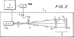
図2は、本発明の第2実施例に従って構成され、参照位相のずれまたは所定変化のための波長同調可能なレーザダイオード光源を用いた、位相ずれ干渉計と関連装置とのブロックダイアグラム表示である。
図3は、本発明の位相ずれ干渉計装置および方法の性能を、位相ずれ較正誤差の存在下での代表的従来技術の研究法と比較した結果を示すグラフである。
図4は、本発明の位相ずれ干渉計装置および方法の性能を、位相ずれの非線形性の存在下での代表的従来技術の研究法と比較した結果を示すグラフである。
図5は、本発明の位相ずれ干渉計装置および方法の性能を、低周波数振動の存在下での代表的従来技術の研究法と比較した結果を示すグラフである。
好ましい実施例の詳細な説明
図1は本発明による第1の好ましい実施例により構成された装置の基本要素を図解的に描いたものであり、この装置は原理的に、コンピュータ1と有名なフィゾー幾何形状の位相ずれ干渉計2とから構成されている。ここで記述される装置の好ましい形態では、コンピュータ1−−特別に構成されるかこの用途に合致したデジタル信号処理装置またはここで開示した機能性を発揮するようプログラムされた汎用目的コンピュータでもよい−−は、干渉計の作動を制御し、かつ本発明による干渉計の作動によって得られる干渉強度データの演算及び分析を取得して実行する。マイケルソン(Michelson)またはツイマン グリーン(Twyman Green)型のような光学的に等価な干渉計幾何形状を代わりに用いることができ、その干渉計幾何形状はこの開示の意図した範囲及び思想の中にあると理解すべきである。
干渉計2は、光学的にコヒーレントな光源3、すなわち図1に示すフィゾー幾何形状で干渉計使用法(interferometry)を行うための十分な分光及び空間純度を持つ光源によって照射される。光源3は、例えばヘリウムネオンレーザのような、この技術分野で知られた通常の構成のレーザであってもよく、電源15から作動電力を受ける。光源3からの光はビームスプリッタ5によって反射され、フィゾー干渉計の空隙6に向かい、そこでその光は平凸レンズ6の凸面7によって平行にされる。レンズ8の平面側9は、参照表面として働くとともに、ビームスプリッタ5を介して光の一部を後方へ反射させ、画像作成レンズ11を経てカメラ10へ導く。カメラ10は、標準的なビデオカメラ、電荷結合素子(CCD)、またはそこに当たる光の強度のに応じた電子画像を発生させるための同様の装置であってもよい。レンズ8を通過する光の一部は、表面形状を測定しようとする対象物13の前面側12から反射される。対象物13から反射された光は、ビームスプリッタ5を介して後方のカメラ10に伝達され、そこで参照表面9から反射された光と干渉する。干渉現象は、カメラ10によって測定されかつコンピュータ1に電子的に移送される強度分布を有する干渉写真図になる。
干渉計2は、対象物または検査中の部分から反射された光の特性、より具体的には反射波面の位相輪郭を測定するために有効に用いられる。カメラが受け取った強度画像は、予め設定され実質的に等間隔に位置する一連の所定数の位相ずれのための、コンピュータを基にする制御装置に記憶される。これらの位相ずれはアセンブリ14によって作られ、そのアセンブリはフィゾー空隙6の長さを変えるべく物理的に前後にレンズ11を移し変えるための電子機械的手段を含む。そのような物理的移し変えは、例えば圧電変換器(PZT)または類似のものによる公知な配置によってなされてもよい。コンピュータ1は選択的に変わる電圧をPZTに供給することにより、レンズの移し変えを有効に制御する。当業者は、フィゾー空隙の長さを干渉計の部品または要素の物理的移し変えを通じて変化させるための他の配置を設計上の選択事項として用いてもよいことを認めるであろう。
本発明の1つの好ましい方法によれば、一連の7つの強度画像は、レンズ11の直線的な移し変えの間に、関連メモリに記憶されるかあるいはコンピュータ1により記録される。このように、7つの強度値gj*がそれぞれの像点ごとにコンピュータメモリに記憶され、それぞれは、
数式1
gj=A・(1+V・cos(Θ+φj))
に等しい。
ここで、Vは干渉じまの鮮明度、Aは全定数、j=0…6は7つのそれぞれの画像に対応する。基準位相ずれφjは、
数式2
![]()
したがって、画像の位相間隔は(少なくともおおよそ)π/2であり、633nmの典型的な照明光源波長λにおいて79nmの連続する画像の間での直線運動に相当するものである。7つの強度画像を記録した後、コンピュータ1は数式3の関係式を用いて波面位相θを計算する。
数式3
Θ=tan-1(T)
ここで、
数式4
![]()
数式5
![]()
第2は、図2に示す本発明の他の装置の実施例であって連続する強度画像の間での干渉計における位相ずれが、「干渉計使用波面測定」と題する米国特許第4,594,003号においてソマグレン(Sommagren)によって教示されたものに類似する方法で、同調可能な光源4の波長を選択的に調節することにより達成される。この波長同調と呼ばれるものは、この第2の装置の実施例の好ましい形態において、レーザーダイオード電源17のコンピュータ制御操作により自動的に実行される。しかしながら、前記ソマグレン特許に記載された4つの強度画像測定結果を用いる代わりに、本発明では、おおよそπ/2の画像間位相ずれに相当する一連の7つの強度画像をコンピュータの記録部に取得し記憶する構成としている。コンピュータ1は次に、数式(3)、(4)及び(5)を用いて対象物表面形状を演算する。数式(5)におけるλは波長同調光源の平均波長である。
本発明は、すべての実際的な目的のためには、従来技術の位相ずれ干渉計使用法とは基本的に異なり、本発明の方法及び装置は、連続する強度画像間の位相ずれにおける誤差、すなわち、位相ずれφjが予想値あるいは意図値とは実際に異なることにより生じる誤差に対して、実質的に鈍感である。仮に、説明の便宜上、実際の位相ずれφjを表す式を、
数式6とする。
![]()
図3は、生じた測定誤差の大きさを数式(6)における較正係数εの関数として、一方に先行技術の方法の使用によるもので、他方に本発明によるもので、比較したグラフを示す。この例における先行技術は、「デジタル位相ずれ干渉計使用法:単純誤差補償、位相算出アルゴリズム、26応用光学2504−06(1987)」と題してP.Hariharan,F.F.Oreb及びT.Eijuによる文献に記述された方法によるものである。その方法は、位相ずれ干渉計使用法を用いた表面形状分析において使用するための現在利用できる最良の方法であると広く一般的に認識されている。図3において明らかなように、先行技術の方法は、光波の1/1000より精度の高い表面高さ測定を維持するために極めて精密な位相ずれの較正を必要とする。他方、本発明の方法及び装置は、位相ずれの較正には本質的に依存しない高精度の表面形状測定を提供する。
図4は、先行技術と本発明の方法について測定誤差の大きさを数式(6)における非線形係数γの関数としてグラフ上で比較した概略を示す。図4のグラフは、先行技術が、光波の1/1000より正確な表面高さ測定を維持するために連続する強度像の間で位相ずれのほぼ完全な線形性を要求しているということを明らかに示す。もう一度繰り返すが、本発明の方法は位相ずれにおける2次非線形性から本質的に依存しない高度に正確な測定精度を提供する。
最後に、図5は、低周波数振動の存在下での先行技術及び本発明の方法について測定誤差の大きさを比較したグラフである。このグラフは、60Hzのビデオカメラを備えた先行技術の機器についての振動数と測定誤差との関係を示す。振動の量は周波数帯にわたって固有値に維持され、光波の約5/1000に等しい干渉計の空隙における機械振動に相当する。図5のグラフは、低周波数帯全体にわたり、振動に対する有意の表面高さ測定誤差を明示し、これらの振動数は製造環境では特にありふれており、重機械、熱運動、気流及び歩行者の通行により生じるものが例示できる。グラフ化されたデータを皮相的に見直したとしても、先行技術の干渉計は、高精度を維持するために大がかりな低周波数振動の隔離を要することを明確に示す。他方、本発明の方法及び装置に対する測定誤差の大きさは、実質的に低減される。本発明はこのように、干渉計機器において振動の大がかりな隔離の、今まで理解されている必要性を有意に低減しあるいは不要とする。
本発明の現在、最も好ましい実施例は、7つの干渉写真図から得られたデータを採用するが、ある応用については、取得し記憶する強度画像の数を6まで減らすことが有利かもしれない。そのような環境下で、本発明の実質的な特徴及び機能は、数式(4)に代わって下記の数式を用いることにより保存される。
数式7
![]()
さらに、本発明の他の実施例は、異なる位相オフセットにおいて取られた2以上の連続する測定値の組を平均化したシステムで構成される。例えば、高反射性の参照及び対象物表面を有するフィゾー空隙において、一方から他方へπ/4だけ互いにれがずれた2つの異なるデータの組に数式(4)を適用するのは有利である。
そのようなオフセットは、都合のよいことには、π/4の位相間隔で14個の強度フレームからなる1つのデータ組を取ることにより得られる。次に数式(3)及び(4)は、すべての偶数番号のフレームまたは強度画像について集めたデータに適用され、次にすべての奇数番号のフレームのデータに再適用される。最終位相値は2つの計算結果の平均である。
フィゾー空隙及び大量の強度ノイズを含むデータに効果を有する、さらに他の実施例は、π/4の位相間隔で13個の強度フレーム(j=0…12)を記録し、次に前述したように、しかし数式(4)に代わる以下の公式を用いて表面高さを計算することからなる。
数式8

(数式1)
gj=A・(1+V・cos(Θ+φj))
及び
数式9
![]()
好ましい実施例に適用した本発明の基本的な新しい特徴を示し記述し指摘したが、本発明の精神から逸脱することなく、当業者によって様々な省略や置き換えや形状の変更や開示された本発明に対する詳細な説明が可能であることは理解されるであろう。ゆえに、本発明は、ここに付された請求の範囲の視点により示されたものに限定されない。 FIELD OF THE INVENTION The present invention relates generally to precision optical measurement instruments for surface imaging and analysis, and more particularly to an apparatus for delineating a longitudinal profile of a surface shape based on an interferometer. And a method.
Background of the invention The most widely used instrument for measuring surface topography is the interferometer, which is a light wave feature to illustrate the change in surface height with high accuracy. Use sex. Today, it is generally accepted by those skilled in the art that the most accurate interferometer in normal use is based on the principle of phase shift. Modern phase shift interferometers typically comprise an optical system, an electronic imaging system, a computer-based or other automated controller, and a means for introducing a reference phase shift.
Phase-shifting interferometer usage ("PSI") is described in detail in
When such a PSI-based instrument is properly tuned, the surface shape can be measured with a resolution on the order of 1/1000 of the wavelength of light.
Certain aspects of all prior art PSI instruments are important for obtaining surface shape measurements with the desired high accuracy. These aspects include precise adjustment of reference and incremental phase changes during interferometer operation, as well as substantially complete isolation of the interferometer from vibrations, particularly low frequency vibrations typical of most manufacturing environments. Is included.
Recently, the most common method and arrangement for introducing the required reference phase shift for PSI is by mechanical translation or movement of the reference surface. The total amount of mechanical movement required for this purpose is usually less than the wavelength of the light and must be carefully (and often repeated) calibrated to produce a repeatable phase shift with appropriate accuracy. Often performed by the controlled operation of a piezoelectric transducer (PZT) or equivalent assembly that must be performed. Another method known to those skilled in the art uses selective tuning of the wavelength of the source light for the interferometer in a manner that results in a small phase shift. This alternative method also requires careful calibration and may even require continuous monitoring of the wavelength of the light source.
It is well known that out-of-phase distortions particularly cause measurement errors that are unacceptable for prior art PSI instruments. A significant error can then occur when the reference phase shift is non-linear or not properly calibrated.
Jay. J. van Wingerden, H. H. Franchena (HHFrankena) and C. In the paper titled “Linear Approximation For Measurement Errors In Phase Shiting Interferometry” [30 Applied Optics 2718-29 (1991)] by C. Smorenburg, These errors are described in some detail, including their form and size.
Kay. Kinstatter, Kew, Wrew. Roman (QWLohmann), Jay. J. Schwider and N.W. Several other papers, such as a paper titled “Accuracy of Phase Shifting Interferometry” (27 Applied Optics 5082-89 (1988)) by N. Streibl The paper describes the need for careful calibration and proposes a special arrangement for measuring the magnitude of the phase shift.
Deviations from linear motion are particularly troublesome in prior art PSI instruments, even with a relatively small degree of non-linearity, can result in unacceptably large errors in the calculated surface height.
As a result, expensive and cumbersome high-voltage PZT assemblies must be used to make the phase shift as linear as possible, and time-consuming operations must be performed to achieve a substantially complete calibration of the phase shift. I must. The problems associated with calibrating and linearizing wavelength shifts have also greatly hampered the widespread use of wavelength tuned laser diodes in interferometers as an alternative to mechanical movement of interferometer components.
Low frequencies and other vibrations that occur during the interferometer data acquisition cycle also significantly distort the phase shift, leading to additional errors that conventional instruments can only remove through careful exclusion of all vibration sources.
Commonly used vibration isolation methods require the use of large granite or air floating tables, along with a heavy framework to support the optical elements of the interferometer. In addition, the measurement system must often be physically isolated from the manufacturing and assembly area, so that it is significantly higher for the manufacturing industry that uses interferometers to verify the surface quality of the manufactured articles. Will cause costs.
Therefore, there is an unmet need for an apparatus and method for accurately measuring the surface shape without relying on the high-precision phase shift mechanism and operation of the prior art and the expensive vibration isolation arrangement method.
Objects of the invention Accordingly, one main object of the present invention is to provide an improved method and apparatus for measuring the topography of a surface using a phase shift interferometer usage. There is.
A further object of the present invention is to measure the surface shape with very high accuracy and nevertheless without careful or accurate calibration of the mechanism in which the phase shift takes place.
It is a further object of the present invention to have significant non-linear motion, and the characteristics of such motion are compatible for high precision surface shape measurement using conventional phase shift interferometer usage methods and apparatus. It is an object of the present invention to provide a method and apparatus capable of obtaining very high measurement accuracy by using a low-cost phase shift mechanism which is not possible or unacceptable.
It is a further object of the present invention to provide an inexpensive and wavelength tunable light source such as a laser diode, the wavelength tuning of which uses a conventional phase shift interferometer method and apparatus for high accuracy surface shape measurement. It is therefore an object of the present invention to provide a method and apparatus that can obtain extremely high measurement accuracy using a light source that is incompatible or unacceptable.
SUMMARY OF THE INVENTION An apparatus constructed in accordance with the present invention for measuring surface topography includes an optical interferometer for developing interference data from a profiled surface, and the interference. Including an electronic imaging system for receiving the interference data from the meter, a computer-based control and data analysis device, and a device or arrangement for variably adjusting the reference phase of the interferometer illumination Yes. In accordance with the preferred method of the present invention, a series of seven intensity images are detected and electronically stored by the imaging system. These intensity images correspond to interference patterns for seven different reference phase values arranged at intervals of approximately π / 2, ie, interference photograph diagrams. The phase value interval (ie, approximately π / 2) need not be exactly the same and need not be repeatable, and low frequency vibrations may also occur during data acquisition for the intensity image. There is no need to eliminate it completely from the optical system. Seven interferograms are created on the computer--using methodologies not known in the prior art--to retrieve the shape of the surface under inspection from the data. Another embodiment of the invention comprises a laser diode based device and method using a combination of six intensity frames, 13 intensity frames and two or more sets of intensity measurements obtained with different phase offset values. Contains.
Additional objects and features of the present invention will become apparent from the following detailed description considered in conjunction with the accompanying drawings. However, it should be understood that the drawings are provided for illustrative purposes only and are not meant to be limiting of the invention, for which the attached Reference should be made to the claims.
[Brief description of the drawings]
In the drawings, like reference numerals indicate like elements throughout the several views.
FIG. 1 is a block diagram representation of a phase shift interferometer and associated devices constructed in accordance with a first embodiment of the present invention and using a mechanical reference phase shift arrangement.
FIG. 2 is a block diagram representation of a phase shift interferometer and associated apparatus using a wavelength tunable laser diode light source configured in accordance with a second embodiment of the present invention for reference phase shift or predetermined change. .
FIG. 3 is a graph showing the results of comparing the performance of the inventive phase shift interferometer apparatus and method with a representative prior art approach in the presence of phase shift calibration errors.
FIG. 4 is a graph showing the results of comparing the performance of the phase shift interferometer apparatus and method of the present invention with a typical prior art approach in the presence of phase shift nonlinearity.
FIG. 5 is a graph showing the results of comparing the performance of the phase shift interferometer apparatus and method of the present invention with a typical prior art approach in the presence of low frequency vibrations.
Detailed description of the preferred embodiment Fig. 1 is a diagrammatic representation of the basic elements of a device constructed according to a first preferred embodiment of the present invention. And the famous Fizeau geometry phase-shifting interferometer 2. In the preferred form of the device described herein, it may be a
The interferometer 2 is illuminated by an optically coherent light source 3, i.e. a light source having sufficient spectral and spatial purity to perform interferometry with the Fizeau geometry shown in FIG. The light source 3 may be a conventional laser known in the art, such as a helium neon laser, and receives operating power from a
The interferometer 2 is effectively used to measure the characteristics of light reflected from the object or the part under inspection, more specifically the phase profile of the reflected wavefront. The intensity image received by the camera is stored in a computer-based controller for a series of a predetermined number of phase shifts that are preset and located at substantially equal intervals. These phase shifts are created by the
According to one preferred method of the invention, a series of seven intensity images are stored in the associated memory or recorded by the
g j = A · (1 + V · cos (Θ + φ j ))
be equivalent to.
Here, V is the sharpness of the interference fringe, A is the total constant, and j = 0... 6 corresponds to each of the seven images. The reference phase shift φ j is
Formula 2
![]()
Thus, the phase spacing of the images is (at least approximately) π / 2, which corresponds to a linear motion between 79 nm successive images at a typical illumination source wavelength λ of 633 nm. After recording seven intensity images, the
Formula 3
Θ = tan -1 (T)
here,
![]()
![]()
Second, another apparatus embodiment of the present invention shown in FIG. 2 in which the phase shift in the interferometer between successive intensity images is described in US Pat. No. 4,594,003 entitled “Interferometer-Based Wavefront Measurement”. This is accomplished by selectively adjusting the wavelength of the tunable
The present invention is fundamentally different from prior art phase-shift interferometer usage for all practical purposes, and the method and apparatus of the present invention provides an error in phase shift between successive intensity images, That is, it is substantially insensitive to an error caused by the fact that the phase shift φ j is actually different from the expected value or the intended value. For convenience of explanation, an expression representing the actual phase shift φ j is
![]()
FIG. 3 shows a graph comparing the magnitude of the resulting measurement error as a function of the calibration factor ε in equation (6), one using the prior art method and the other using the present invention. The prior art in this example is described in the literature by P. Hariharan, FFOreb and T. Eiju under the title "Digital phase shift interferometer usage: Simple error compensation, phase calculation algorithm, 26 Applied Optics 2504-06 (1987)". It is by the method that was done. The method is widely and generally recognized as the best method currently available for use in surface shape analysis using phase shift interferometer usage. As can be seen in FIG. 3, the prior art method requires a very precise phase shift calibration to maintain surface height measurements more accurate than 1/1000 of the light wave. On the other hand, the method and apparatus of the present invention provides highly accurate surface shape measurements that are essentially independent of phase shift calibration.
FIG. 4 shows a schematic comparison of the measurement error magnitude on the graph as a function of the nonlinear coefficient γ in Equation (6) for the prior art and the method of the present invention. The graph in FIG. 4 shows that the prior art requires almost perfect linearity of phase shift between successive intensity images in order to maintain a surface height measurement that is more accurate than 1/1000 of the light wave. Show clearly. Again, the method of the present invention provides a highly accurate measurement accuracy that is essentially independent of second order nonlinearities in phase shift.
Finally, FIG. 5 is a graph comparing the magnitude of the measurement error for the prior art and the method of the present invention in the presence of low frequency vibrations. This graph shows the relationship between frequency and measurement error for a prior art device with a 60 Hz video camera. The amount of vibration is maintained at an eigenvalue over the frequency band and corresponds to mechanical vibrations in the interferometer air gap equal to about 5/1000 of the light wave. The graph in FIG. 5 demonstrates significant surface height measurement errors for vibrations throughout the low frequency band, and these frequencies are particularly common in the manufacturing environment and include heavy machinery, thermal motion, airflow and pedestrian traffic. Can be exemplified. Even if the graphed data is reviewed apparently, prior art interferometers clearly show that large low frequency vibration isolation is required to maintain high accuracy. On the other hand, the magnitude of measurement error for the method and apparatus of the present invention is substantially reduced. The present invention thus significantly reduces or eliminates the need to be understood to date for the isolation of large vibrations in interferometer equipment.
Although the presently most preferred embodiment of the present invention employs data obtained from seven interferograms, for some applications it may be advantageous to reduce the number of intensity images acquired and stored to six. Under such circumstances, the substantial features and functions of the present invention are preserved by using the following mathematical formula instead of the mathematical formula (4).
![]()
In addition, another embodiment of the present invention comprises a system that averages a set of two or more consecutive measurements taken at different phase offsets. For example, in a Fizeau gap with a highly reflective reference and object surface, it is advantageous to apply equation (4) to two different data sets that are offset from each other by π / 4.
Such an offset is conveniently obtained by taking one data set of 14 intensity frames with a phase interval of π / 4. Equations (3) and (4) are then applied to the data collected for all even-numbered frames or intensity images and then re-applied to the data for all odd-numbered frames. The final phase value is the average of the two calculation results.
Yet another embodiment, which has an effect on data including Fizeau gaps and large amounts of intensity noise, records 13 intensity frames (j = 0... 12) with a phase interval of π / 4, and then as described above. However, it consists in calculating the surface height using the following formula instead of equation (4).
g j = A · (1 + V · cos (Θ + φ j ))
And
![]()
While the invention has been shown, described and pointed out with respect to the basic features of the invention as applied to the preferred embodiment, various omissions, substitutions, changes in shape and disclosed inventions by those skilled in the art without departing from the spirit thereof It will be understood that a detailed description is possible. Accordingly, the invention is not limited to that shown by the scope of the claims appended hereto.
Claims (10)
その位置が画像装置と光学的に一列になる位相ずれ干渉計の光軸に沿った前記表面の位置決めのステップと、
光学的にコヒーレントな波長λの照明光源を用いてその表面位置の、前記画像装置上での干渉パターンの作成のステップと、
それぞれがおおよそπ/2の位相差によって他のものから連続的にずれている7つのフレームj−−j=0……6−−に対して前記表面位置のための強度データgjを前記画像装置上に作成する干渉計の作動のステップと、
前記7つのフレームjに対して前記画像装置上に作成された強度データgjの電子的な記憶のステップと、
式
式
を備えている方法。A method for determining the height of a position on a surface,
Positioning the surface along the optical axis of a phase shift interferometer whose position is optically aligned with the imaging device;
Creating an interference pattern of the surface position on the imaging device using an optically coherent wavelength λ illumination source;
The intensity data g j for the surface position for the seven frames j--j = 0... 6-- each of which is continuously displaced from the others by a phase difference of approximately π / 2, The steps of operating the interferometer created on the device;
Electronic storage of intensity data g j created on the imaging device for the seven frames j;
formula
formula
前記7つのフレームnに対して前記画像装置上に作成された強度データgnの電子的な記憶のステップと、
式
式
をさらに備え、
前記表面位置の高さhの演算のステップが
式
請求項1の方法。Seven frames n, each of which is continuously displaced from the others by a phase difference of approximately π / 2--the seven frames n are alternately superimposed on the seven frames j to approximately π from those frames j / 4 and n = 7... 13—the step of operating the interferometer to produce intensity data g n on the imaging device for-
Electronic storage of intensity data g n generated on the imaging device for the seven frames n;
formula
formula
The step of calculating the height h of the surface position is an expression
その位置が画像装置と光学的に一列になる位相ずれ干渉計の光軸に沿った前記表面の位置決めのステップと、
光学的にコヒーレントな波長λの照明光源を用いてその表面位置の、前記画像装置上での干渉パターンの作成のステップと、
それぞれがおおよそπ/2の位相差によって他のものから連続的にずれている6つのフレームj−−j=0……5−−に対して前記表面位置のための強度データgjを前記画像装置上に作成する干渉計の作動のステップと、
前記6つのフレームjに対して前記画像装置上に作成された強度データgjの電子的な記憶のステップと、
式
式
を備えてなる方法。A method for determining the height of a position on a surface,
Positioning the surface along the optical axis of a phase shift interferometer whose position is optically aligned with the imaging device;
Creating an interference pattern of the surface position on the imaging device using an optically coherent wavelength λ illumination source;
The intensity data g j for the surface position for the six frames j--j = 0... 5-- each of which is successively displaced from the others by a phase difference of approximately π / 2, The steps of operating the interferometer created on the device;
Electronic storage of intensity data g j created on the imaging device for the six frames j;
formula
formula
その位置が画像装置と光学的に一列になる位相ずれ干渉計の光軸に沿った前記表面の位置決めのステップと、
光学的にコヒーレントな波長λの照明光源を用いてその表面位置の、前記画像装置上での干渉パターンの作成のステップと、
それぞれがおおよそπ/4の位相差によって他のものから連続的にずれている13個のフレームj−−j=0……12−−に対して前記表面位置のための強度データgjを前記画像装置上に作成する干渉計の作動のステップと、
前記13個のフレームのために前記画像装置上に作成された強度データgjの電子的な記憶のステップと、
式
式
を備えてなる方法。A method for determining the height of a position on a surface,
Positioning the surface along the optical axis of a phase shift interferometer whose position is optically aligned with the imaging device;
Creating an interference pattern of the surface position on the imaging device using an optically coherent wavelength λ illumination source;
The intensity data g j for the surface position for 13 frames j--j = 0... 12-- each of which is continuously shifted from the others by a phase difference of approximately π / 4. The steps of operating the interferometer created on the imaging device;
Electronic storage of intensity data g j created on the imaging device for the 13 frames;
formula
formula
Applications Claiming Priority (3)
| Application Number | Priority Date | Filing Date | Title |
|---|---|---|---|
| US08/242,789 US5473434A (en) | 1994-05-16 | 1994-05-16 | Phase shifting interferometer and method for surface topography measurement |
| US08/242,789 | 1994-05-16 | ||
| PCT/US1995/006531 WO1995031694A1 (en) | 1994-05-16 | 1995-05-15 | Improved phase shifting interferometer and method for surface topography measurement |
Publications (2)
| Publication Number | Publication Date |
|---|---|
| JPH10500486A JPH10500486A (en) | 1998-01-13 |
| JP3633625B2 true JP3633625B2 (en) | 2005-03-30 |
Family
ID=22916191
Family Applications (1)
| Application Number | Title | Priority Date | Filing Date |
|---|---|---|---|
| JP52991795A Expired - Fee Related JP3633625B2 (en) | 1994-05-16 | 1995-05-15 | Improved phase shift interferometer and surface shape measuring method |
Country Status (5)
| Country | Link |
|---|---|
| US (1) | US5473434A (en) |
| EP (1) | EP0760085B1 (en) |
| JP (1) | JP3633625B2 (en) |
| DE (1) | DE69516136T2 (en) |
| WO (1) | WO1995031694A1 (en) |
Families Citing this family (49)
| Publication number | Priority date | Publication date | Assignee | Title |
|---|---|---|---|---|
| US5956355A (en) * | 1991-04-29 | 1999-09-21 | Massachusetts Institute Of Technology | Method and apparatus for performing optical measurements using a rapidly frequency-tuned laser |
| US6033721A (en) * | 1994-10-26 | 2000-03-07 | Revise, Inc. | Image-based three-axis positioner for laser direct write microchemical reaction |
| US5680214A (en) * | 1996-03-22 | 1997-10-21 | Wyko Corporation | Horizontal-post/vertical-flexure arrangement for supporting large reference optics in phase-shifting scanning |
| US5999263A (en) * | 1998-01-26 | 1999-12-07 | Zygo Corporation | Method and apparatus for performing interferometric measurements with reduced sensitivity to vibration |
| US6181430B1 (en) | 1999-03-15 | 2001-01-30 | Ohio Aerospace Institute | Optical device for measuring a surface characteristic of an object by multi-color interferometry |
| US6359692B1 (en) | 1999-07-09 | 2002-03-19 | Zygo Corporation | Method and system for profiling objects having multiple reflective surfaces using wavelength-tuning phase-shifting interferometry |
| US6894788B2 (en) * | 2000-11-20 | 2005-05-17 | Zygo Corporation | Interferometric system for automated radius of curvature measurements |
| DE10130902A1 (en) * | 2001-06-27 | 2003-01-16 | Zeiss Carl | Interferometer system, method for recording an interferogram and method for providing and producing an object with a target surface |
| US7030995B2 (en) * | 2001-12-10 | 2006-04-18 | Zygo Corporation | Apparatus and method for mechanical phase shifting interferometry |
| US20080137098A1 (en) * | 2002-01-25 | 2008-06-12 | Mater Michael J | Method of multiple wavelength interferometry |
| TW523085U (en) * | 2002-04-11 | 2003-03-01 | K Laser Technology Inc | Continuous zooming image forming interferometer |
| US7130059B2 (en) * | 2002-06-24 | 2006-10-31 | Light Gage, Inc | Common-path frequency-scanning interferometer |
| EP1649241A1 (en) * | 2002-11-21 | 2006-04-26 | Carl Zeiss SMT AG | Method for calibrating an interferometer, method for qualifying an object, and method for producing an object |
| US6885461B2 (en) * | 2002-12-03 | 2005-04-26 | Phase Shift Technology, Inc. | Weighted least-square interferometric measurement of multiple surfaces |
| US6856405B2 (en) * | 2003-03-03 | 2005-02-15 | Phase Shift Technology, Inc. | Non linear phase shift calibration for interferometric measurement of multiple surfaces |
| US6847458B2 (en) * | 2003-03-20 | 2005-01-25 | Phase Shift Technology, Inc. | Method and apparatus for measuring the shape and thickness variation of polished opaque plates |
| DE10392876B4 (en) * | 2003-06-23 | 2007-06-28 | Lightgage Inc. | Multi-stage interferometric fluctuations interpreting process for frequency-scanning interferometer, involves performing two approximations of interference frequency relating to number of cycles |
| US7050175B1 (en) | 2003-08-08 | 2006-05-23 | Carl Zeiss Smt Ag | Method for calibrating an interferometer apparatus, for qualifying an optical surface, and for manufacturing a substrate having an optical surface |
| US7436504B2 (en) * | 2003-09-10 | 2008-10-14 | Shear Graphics, Llc | Non-destructive testing and imaging |
| US6934018B2 (en) * | 2003-09-10 | 2005-08-23 | Shearographics, Llc | Tire inspection apparatus and method |
| US7187437B2 (en) | 2003-09-10 | 2007-03-06 | Shearographics, Llc | Plurality of light sources for inspection apparatus and method |
| US7289222B1 (en) | 2003-10-31 | 2007-10-30 | Carl Zeiss Smt Ag | Interferometer apparatus and method of processing a substrate having an optical surface |
| US7342667B1 (en) | 2003-11-26 | 2008-03-11 | Carl Zeiss Smt Ag | Method of processing an optical element using an interferometer having an aspherical lens that transforms a first spherical beam type into a second spherical beam type |
| US7123365B1 (en) | 2004-03-05 | 2006-10-17 | Carl Zeiss Smt Ag | Method of calibrating an interferometer optics and method of processing an optical element having an aspherical surface |
| US20050225774A1 (en) * | 2004-04-05 | 2005-10-13 | Carl Zeiss Smt Ag | Method for measuring and manufacturing an optical element and optical apparatus |
| US7167251B1 (en) | 2004-05-14 | 2007-01-23 | Carl Zeiss Smt Ag | Method of processing an optical substrate |
| US7728987B2 (en) * | 2004-05-14 | 2010-06-01 | Carl Zeiss Smt Ag | Method of manufacturing an optical element |
| US7061626B1 (en) | 2004-05-14 | 2006-06-13 | Carl Zeiss Smt Ag | Method of manufacturing an optical element using a hologram |
| US7259860B2 (en) * | 2004-09-22 | 2007-08-21 | Corning Incorporated | Optical feedback from mode-selective tuner |
| US7268889B2 (en) * | 2004-09-22 | 2007-09-11 | Corning Incorporated | Phase-resolved measurement for frequency-shifting interferometry |
| US7405833B2 (en) * | 2004-11-05 | 2008-07-29 | Zygo Corporation | Method for calibration and removal of wavefront errors |
| US7274467B2 (en) * | 2005-01-04 | 2007-09-25 | Carl Zeiss Smt Ag | Phase shifting interferometric method, interferometer apparatus and method of manufacturing an optical element |
| US7436520B1 (en) | 2005-01-18 | 2008-10-14 | Carl Zeiss Smt Ag | Method of calibrating an interferometer optics and of processing an optical element having an optical surface |
| US7848031B2 (en) * | 2005-01-20 | 2010-12-07 | Carl Zeiss Smt Ag | Hologram and method of manufacturing an optical element using a hologram |
| US7522292B2 (en) | 2005-03-11 | 2009-04-21 | Carl Zeiss Smt Ag | System and method for determining a shape of a surface of an object and method of manufacturing an object having a surface of a predetermined shape |
| US20060274325A1 (en) * | 2005-05-23 | 2006-12-07 | Carl Zeiss Smt Ag | Method of qualifying a diffraction grating and method of manufacturing an optical element |
| US7675628B2 (en) * | 2006-09-07 | 2010-03-09 | 4D Technology Corporation | Synchronous frequency-shift mechanism in Fizeau interferometer |
| JP5153120B2 (en) * | 2006-11-02 | 2013-02-27 | オリンパス株式会社 | Fringe scan interference fringe measurement method and interferometer |
| WO2008076979A1 (en) * | 2006-12-18 | 2008-06-26 | Zygo Corporation | Sinusoidal phase shifting interferometry |
| US7602502B2 (en) * | 2007-04-11 | 2009-10-13 | Carl Zeiss Smt Ag | Methods of testing and manufacturing optical elements |
| US8004688B2 (en) | 2008-11-26 | 2011-08-23 | Zygo Corporation | Scan error correction in low coherence scanning interferometry |
| US8107084B2 (en) | 2009-01-30 | 2012-01-31 | Zygo Corporation | Interference microscope with scan motion detection using fringe motion in monitor patterns |
| US7948637B2 (en) * | 2009-03-20 | 2011-05-24 | Zygo Corporation | Error compensation in phase shifting interferometry |
| JP5543765B2 (en) * | 2009-12-08 | 2014-07-09 | 株式会社ミツトヨ | Fizeau interferometer and measurement method of Fizeau interferometer |
| US8692999B1 (en) | 2011-06-23 | 2014-04-08 | Exelis, Inc. | Crosstalk cancellation for a simultaneous phase shifting interferometer |
| DE102014113289B4 (en) | 2014-09-16 | 2016-04-28 | Helmholtz-Zentrum Berlin Für Materialien Und Energie Gmbh | Method for determining a position of an object |
| WO2016094851A1 (en) * | 2014-12-12 | 2016-06-16 | Sunedison Semiconductor Limited | Systems and methods for performing phase shift interferometry while a wafer is vibrating |
| US10241131B2 (en) * | 2016-08-28 | 2019-03-26 | Bruker Nano, Inc. | Method and apparatus for chemical and optical imaging with a broadband source |
| CN114485473B (en) * | 2022-02-21 | 2024-01-30 | 上海电机学院 | Laser interference phase demodulation method based on component synthesis and gradient projection |
Family Cites Families (12)
| Publication number | Priority date | Publication date | Assignee | Title |
|---|---|---|---|---|
| DE2851750B1 (en) * | 1978-11-30 | 1980-03-06 | Ibm Deutschland | Method and device for measuring the flatness of the roughness or the radius of curvature of a measuring surface |
| US4576479A (en) * | 1982-05-17 | 1986-03-18 | Downs Michael J | Apparatus and method for investigation of a surface |
| US4594003A (en) * | 1983-07-20 | 1986-06-10 | Zygo Corporation | Interferometric wavefront measurement |
| US4606638A (en) * | 1983-11-03 | 1986-08-19 | Zygo Corporation | Distance measuring interferometer and method of use |
| US4818110A (en) * | 1986-05-06 | 1989-04-04 | Kla Instruments Corporation | Method and apparatus of using a two beam interference microscope for inspection of integrated circuits and the like |
| US4732483A (en) * | 1987-03-19 | 1988-03-22 | Zygo Corporation | Interferometric surface profiler |
| US4869593A (en) * | 1988-04-22 | 1989-09-26 | Zygo Corporation | Interferometric surface profiler |
| DE3836564A1 (en) * | 1988-10-27 | 1990-05-03 | Zeiss Carl Fa | METHOD FOR TESTING OPTICAL ELEMENTS |
| IL100655A (en) * | 1991-02-08 | 1994-11-28 | Hughes Aircraft Co | Interferometric laser profilometer |
| DE4204857C2 (en) * | 1991-02-18 | 1998-01-22 | Asahi Optical Co Ltd | Method for examining a surface shape with an interferometer |
| JP2838171B2 (en) * | 1991-03-27 | 1998-12-16 | 株式会社ミツトヨ | Phase shift micro Fizeau interferometer |
| DE4124223C2 (en) * | 1991-07-22 | 2001-07-26 | Zeiss Carl | Procedure for evaluating interferograms and interferometers |
-
1994
- 1994-05-16 US US08/242,789 patent/US5473434A/en not_active Expired - Lifetime
-
1995
- 1995-05-15 DE DE69516136T patent/DE69516136T2/en not_active Expired - Lifetime
- 1995-05-15 WO PCT/US1995/006531 patent/WO1995031694A1/en active IP Right Grant
- 1995-05-15 JP JP52991795A patent/JP3633625B2/en not_active Expired - Fee Related
- 1995-05-15 EP EP95920627A patent/EP0760085B1/en not_active Expired - Lifetime
Also Published As
| Publication number | Publication date |
|---|---|
| DE69516136D1 (en) | 2000-05-11 |
| EP0760085B1 (en) | 2000-04-05 |
| DE69516136T2 (en) | 2001-01-11 |
| WO1995031694A1 (en) | 1995-11-23 |
| US5473434A (en) | 1995-12-05 |
| EP0760085A1 (en) | 1997-03-05 |
| JPH10500486A (en) | 1998-01-13 |
| EP0760085A4 (en) | 1997-03-19 |
Similar Documents
| Publication | Publication Date | Title |
|---|---|---|
| JP3633625B2 (en) | Improved phase shift interferometer and surface shape measuring method | |
| JP2679876B2 (en) | Method and apparatus for measuring surface topography by spatial frequency analysis of interferograms | |
| US5589938A (en) | Method and apparatus for optical interferometric measurements with reduced sensitivity to vibration | |
| US6359692B1 (en) | Method and system for profiling objects having multiple reflective surfaces using wavelength-tuning phase-shifting interferometry | |
| US6987570B1 (en) | Reference signal for stitching of interferometric profiles | |
| US4682025A (en) | Active mirror wavefront sensor | |
| US7933025B2 (en) | Sinusoidal phase shifting interferometry | |
| US7030995B2 (en) | Apparatus and method for mechanical phase shifting interferometry | |
| KR20000029880A (en) | Method and device for heterodyne interferometer error correction | |
| Lewis | Measurement of length, surface form and thermal expansion coefficient of length bars up to 1.5 m using multiple-wavelength phase-stepping interferometry | |
| US6856405B2 (en) | Non linear phase shift calibration for interferometric measurement of multiple surfaces | |
| Decker et al. | Next-generation Kösters interferometer | |
| JP3304111B2 (en) | Apparatus and method for measuring refractive index distribution of refractive index distribution type optical element | |
| JP5544679B2 (en) | Step surface shape measuring method and measuring device | |
| US7538887B1 (en) | Temporal interferometric signal modeling with constant phase shift in white light interferometry | |
| Schmit et al. | White-light interferometry with reference signal | |
| Kim et al. | White light phase-shifting interferometry with self-compensation of PZT scanning errors | |
| Boebel et al. | Phase shifting in an oblique incidence interferometer | |
| Wyant | Advances in interferometric surface measurement | |
| Salbut et al. | Modification of the Koster interferometer for automatization of gauge block measurements | |
| De Veuster et al. | In-line phase-shifter calibration and drift measurement and compensation for digital speckle pattern interferometry (DSPI) | |
| Yongqian et al. | Elimination of reference phase errors in phase-shifting interferometry | |
| Germer et al. | Linearizing the vertical scale of an interferometric microscope and its effect on step-height measurement | |
| JP2805045B2 (en) | Spatial positioning method | |
| JPH0466803A (en) | Method for calibrating phase modulating mechanism in fringe scanning interference measuring method |
Legal Events
| Date | Code | Title | Description |
|---|---|---|---|
| A601 | Written request for extension of time |
Free format text: JAPANESE INTERMEDIATE CODE: A601 Effective date: 20031212 |
|
| A602 | Written permission of extension of time |
Free format text: JAPANESE INTERMEDIATE CODE: A602 Effective date: 20040202 |
|
| TRDD | Decision of grant or rejection written | ||
| A01 | Written decision to grant a patent or to grant a registration (utility model) |
Free format text: JAPANESE INTERMEDIATE CODE: A01 Effective date: 20041130 |
|
| A61 | First payment of annual fees (during grant procedure) |
Free format text: JAPANESE INTERMEDIATE CODE: A61 Effective date: 20041221 |
|
| R150 | Certificate of patent or registration of utility model |
Free format text: JAPANESE INTERMEDIATE CODE: R150 |
|
| FPAY | Renewal fee payment (event date is renewal date of database) |
Free format text: PAYMENT UNTIL: 20090107 Year of fee payment: 4 |
|
| FPAY | Renewal fee payment (event date is renewal date of database) |
Free format text: PAYMENT UNTIL: 20100107 Year of fee payment: 5 |
|
| LAPS | Cancellation because of no payment of annual fees |