JP3629575B2 - Non-element mixing / reactor - Google Patents
Non-element mixing / reactor Download PDFInfo
- Publication number
- JP3629575B2 JP3629575B2 JP2003081943A JP2003081943A JP3629575B2 JP 3629575 B2 JP3629575 B2 JP 3629575B2 JP 2003081943 A JP2003081943 A JP 2003081943A JP 2003081943 A JP2003081943 A JP 2003081943A JP 3629575 B2 JP3629575 B2 JP 3629575B2
- Authority
- JP
- Japan
- Prior art keywords
- fluid
- pipe
- mixing
- reactor
- branch pipe
- Prior art date
- Legal status (The legal status is an assumption and is not a legal conclusion. Google has not performed a legal analysis and makes no representation as to the accuracy of the status listed.)
- Expired - Fee Related
Links
Images


Description
【0001】
【発明の属する技術分野】
本発明は、ノンエレメント混合・反応器に関し、特に、スタティックミキサーのような内部に曲線によって形づくられた部品(エレメント)を有しない混合器(ミキサー)あるいは反応器(リアクター)に関するものであり、機械工学、化学工学、生物・生体工学、医用・医療工学、食品工学等の分野に適用できるものである。特に、今後の展開が期待される、ナノ・マイクロマシン分野、新材料開発分野、バイオ技術分野、医療分野での問題に対応する機器に関するものである。
【0002】
【従来の技術】
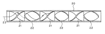
従来、乱流でなくカオス対流(カオス混合)(非特許文献1)を用いた混合・反応器として、スタティックミキサーが知られている(非特許文献2)。スタティックミキサーは可動部・動力部を持たない静止型混合器であり、内部に曲線によって形づくられた部品(エレメント)を有しており、その例を図8に示す。円筒形状の管30内部(内側)に配置されるスタティックミキサーエレメントは、左方向にねじられた羽根形状をした左ねじり羽根31と、右方向にねじられた羽根形状をした右ねじり羽根32とを交互に複数接合してなる形状を有するものであって、隣接する左ねじり羽根31の端部と右ねじり羽根32の端部との交叉角度は90°である。このようなスタティックミキサーは、分割・転換・反転の作用により流体33を効果的に混合する。すなわち、
分割作用…流体33は1つのエレメント31、32を通過する毎に2分割される。
【0003】
転換作用…流体33はエレメント31、32内のねじれ面に沿って管30中央部から壁部へ、管30壁部から中央部へと並び替えられる。
【0004】
反転作用…流体33は1エレメント31、32毎に回転方向が替わり、急激な慣性力の反転を受けて撹拌される。
【0005】
【非特許文献1】
植田利久「反応系の流体力学」(2002年11月18日 コロナ社発行)pp.156〜176
【0006】
【非特許文献2】
J.M.Ottino「The kinematics of mixing:stretching,chaos,and transport 」(1989年 Cambridge University Press 発行)pp.220〜243
【0007】
【発明が解決しようとする課題】
このような従来のスタティックミキサーは、カオス混合技術を応用した効率の高い混合機器であるが、内部に曲線によって形づくられたエレメントを有していることから、次のような欠点を有している。
【0008】
・ナノ・マイクロマシン分野
ナノ・マイクロマシン分野では、機械自体の大きさをできる限り小さくしたい。ところが、エレメントを有するスタティックミキサーでは、エレメントの大きさの制約を受け、ある程度以下の大きさの混合器とすることができない。また、小型化した場合、エレメントのよる圧力損失も相対的に増加する。
【0009】
・新材料開発分野
近年、新材料開発に用いられる素材には非ニュートン流体が多い。非ニュートン流体には、多くの場合、高分子物質等が含まれており、エレメントがある場合には、エレメントによって流体中に含まれる高分子物質が破壊される場合がある。
【0010】
・バイオ技術分野
バイオ技術分野では、微生物等を含むいわゆるバイオ流を対象にしているが、バイオリアクター等では、このバイオ流中にさまざまな物質を分散させなければならない。その際、従来のスタティックミキサーでは、エレメントにより大きな剪断を生じ、微生物の一部が死滅する可能性があり、また、その付着が液体を汚染する場合がある。
【0011】
・医療分野
医療分野において重要なことは、血液等が流れる場合、流路の衛生管理が最も重要な問題となる。エレメントが入っていると、そのエレメントにさまざまな物が付着し、洗浄を十分に行わなければ衛生上問題を生じることになる。また、生体液体は、赤血球等さまざま物質を含んでおり、新材料開発分野と同様、エレメントにより液体内部構造を破壊する可能性もある。
【0012】
本発明は従来技術のこのような問題点に鑑みてなされたものであり、その目的は、内部にエレメントを持つことなく、カオス対流を流れ場を制御することにより実現して、高粘性流体、高分子物質等を含む非ニュートン流体、微生物等を含む生物流、生体流における混合・反応を促進することのできるノンエレメント混合・反応器を提供することである。
【0013】
【課題を解決するための手段】
上記目的を達成する本発明のノンエレメント混合・反応器は、第1の流体と第2の流体を混合又は混合して反応させる混合・反応器において、第1の流体を導入する導入端と混合された流体を排出する排出端と有する断面形状が軸方全ての位置で等しい主流管を備え、前記主流管の側面に導通して上流から下流にかけて複数の支流管が間隔をおいて設けられ、前記主流管の導入端には第1の流体を定常的に供給する第1流体供給手段が連結され、前記支流管の各導入端には、流量を周期的に変化させながら第2の流体を注入する第2流体供給手段が連結されていることを特徴とするものである。
【0014】
この場合に、第2流体供給手段としては、第2の流体を矩形波状に間欠送りするものとすることが望ましい。
【0015】
また、支流管の少なくとも1つに対し、主流管の中心軸を挟んで略対向する側面に別の支流管を設けるようにしてもよい。
【0016】
あるいは、支流管の少なくとも1つに対し、主流管の中心軸を含む平面に対して略対称位置に別の支流管を設けるようにしてもよい。
【0017】
本発明の別のノンエレメント混合・反応器は、第1の流体と第2の流体を混合又は混合して反応させる混合・反応器において、第1の流体を導入する導入端と混合された流体を排出する排出端と有する主流管を備え、前記主流管の側面に導通して少なくとも1つの枝管が取り付けられており、前記枝管内に支流管が前後に移動可能に配置されて前記支流管の先端が前記主流管の内部を移動するように構成され、かつ、前記支流管を周期的に駆動する駆動手段が前記支流管に取り付けられており、前記主流管の導入端には第1の流体を定常的に供給する第1流体供給手段が連結され、前記支流管の導入端には、第2の流体を供給する第2流体供給手段が連結されていることを特徴とするものである。
【0018】
本発明においては、エレメントを用いることなく流体中で混合物質の引き伸ばしと折り畳みを行ってカオス混合を行わせ、層流低剪断混合を実現することができる。そのため、エレメントの大きさに制約を受けずに混合・反応器を小型化ができ、流体中に含まれる高分子物質、微生物等の液体内部構造の破壊、死滅を起こすことがなく、洗浄も簡単で衛生上の問題も起こり難くなり、高粘性流、非ニュートン流、バイオ流、生体流における混合・反応に適した混合・反応器を提供することができる。
【0019】
【発明の実施の形態】
本発明のノンエレメント混合・反応器の基本原理は、スタティックミキサーと同様に、カオス対流(カオス混合)によるものである。スタティックミキサーでは、カオス対流を内部のエレメントにより実現させているが、本発明のノンエレメント混合・反応器では、混合される一方の流体の流れの中に混合される他方の流体を流量を周期的に変化させながら注入するか、あるいは、注入位置を周期的に変化させながら注入することによりカオス対流を実現するものである。
【0020】
ここで、カオス対流(カオス混合)とは、流体の要素が引き伸ばしと折り畳みという変形を指数関数的に行い流体場の中に広がって行く現象であり、2つの流体塊があるときには、この2つの流体塊は分子オーダーで近づいて混合が促進されていき、反応物質の分子拡散領域が重なる程に流体が近づき、化学反応が促進される。このような混合がカオス混合と呼ばれる。
【0021】
さて、本発明のノンエレメント混合・反応器の基本形を説明する。図1に模式的に示すように、2つの流体(液体)A及びBの混合を考える。流体Aは主流として円管(主流管)1内を定常的に流される。流体Aに混合をさせたい液体Bを、流量を周期的に変化させながら円管1の側面から注入する。円管1内に液体Bを周期的に注入することにより、図に示したように、液体Bは円管1内の液体A中で引き伸ばしと折り畳みを受け、さらに、流体Aが円管1内に形成する速度分布(壁面では速度ゼロ、中心部分では最大速度になる放物線状の分布)の影響を受けることにより、引き伸ばしと折り畳みがさらに促進されて、流体Aと流体Bのカオス的な混合が実現される。
【0022】
実際には、特別の場合を除いて、図1のような基本形のユニットを複数(5〜20個程度)用いてそれらを縦列に連結し、その中を流体Aを定常的に流し、各ユニットに設けられた支流管各々から液体Bを周期的に注入することにより、両液体A、Bの引き伸ばしと折り畳みをさらに促進して流体Aと流体Bのカオス混合を実現する。
【0023】
以下、本発明のノンエレメント混合・反応器を構成するユニットについて説明する。
【0024】
第1の形態のユニット11は、図2(a)に示すように、1つ主流管1に1本の支流管2を側面に取り付けたものである。この際のパラメータとしては、主流管1の流れ方向の長さLと、支流管2の入口からの取り付け距離L1 と、支流管2の主流管1中心軸方向への倒れ角φ1 と、支流管2取り付け位置の主流管1中心軸からのずれ量λである。例えば、図2(b)に正面図、図2(b)’に斜視図を示すように、λが略ゼロのもの、図2(c)、図2(c)’に同様の図を示すように、λが主流管1の半径の1/2程度のもの、図2(d)、図2(d)’に同様の図を示すように、λが主流管1の半径の1/2より大きなもの等がある。特に、λがゼロ以外のものにおいては、液体の引き伸ばしと折り畳みを3次元的に行わせることが可能になり、カオス的な混合をより促進することができる。
【0025】
なお、本発明のノンエレメント混合・反応器は、流路途中に支流から混合させる別の流体を注入するため、上流からの流速が遅い場合、逆流が生じる場合がある。そこで、その逆流が生じる区間に、図3に示すような円管3からなる助走部ユニット10を用いる。
【0026】
図4は、このような助走部ユニット10と複数(6個)のユニット11を縦列に連結して構成した本発明の1実施例のノンエレメント混合・反応器100の構成を示す図である。このようなノンエレメント混合・反応器100の本体の主流管の上流に連結管32を介して液槽31が連結され、また、各ユニット11の支流管2は、枝分かれ管33を介して例えば人工心肺用のポンプのような矩形波状に液体を間欠送りできるポンプ34の吐き出し側に連結される。そして、そのポンプ34の吸い込み側には、連結管36を介して液槽35が連結される。さらに、ノンエレメント混合・反応器100の主流管の下流には、連結管37を介して液槽38に連結される。
【0027】
このような構成において、液槽31に液体Aが、液槽35に液体Bが入れられ、液槽31から重力により液体Aが助走部ユニット10の円管3と複数のユニット11の主流管1とを経て一定流量で送られ、また、ポンプ34により液槽35から液体Bが各ユニット11の支流管2を経てそれぞれの主流管1内に矩形波状に間欠的に注入される。このような配置により、1個のユニット11中で行われる図1で説明したような両液体A、Bの引き伸ばしと折り畳みがその段数分促進されて流体Aと流体Bがカオス混合されて一様に混合・反応されていく。
【0028】
図4のように縦列に連結する主流管1と支流管2からなるユニットとしては、図2のようなものに限らず、他の形態のユニットも可能である。図5に第2の形態のユニット12、図6に第3の形態のユニット13を示す。
【0029】
図5の第2の形態のユニット12は、1つ主流管1の中心軸を挟んで対向する側面に2本の支流管2、2を取り付けたものである。この際のパラメータとしては、主流管1の流れ方向の長さLと、各支流管2の入口からの取り付け距離L1 、L2 と、各支流管2の主流管1中心軸方向への倒れ角φ1 、φ2 と、各支流管2の主流管1横断面内での倒れ角θ1 、θ2 と、支流管2の主流管1中心軸からのずれ量λである。例えば、図5(b)に正面図を示すように、λが略ゼロのもの、図5(c)に同様の図を示すように、λが主流管1の半径の1/2程度のもの、図5(d)に同様の図を示すように、λが主流管1の半径の1/2より大きなもの等がある。特に、λがゼロ以外のものにおいては、液体の引き伸ばしと折り畳みを3次元的に行わせることが可能になり、カオス的な混合をより促進することができる。
【0030】
図6の第3の形態のユニット13は、1つ主流管1の中心軸を含む平面に対して対称位置に2本の支流管2、2を取り付けたものである。この際のパラメータとしては、主流管1の流れ方向の長さLと、各支流管2の入口からの取り付け距離L1 、L2 と、各支流管2の主流管1中心軸方向への倒れ角φ1 、φ2 と、各支流管2の主流管1横断面内での倒れ角θ1 、θ2 と、支流管2の主流管1中心軸からのずれλである。この場合は、液体の引き伸ばしと折り畳みを3次元的に行わせることが可能になり、カオス的な混合をより促進することができる。
【0031】
このようなユニット12あるいはユニット13を図4のユニット11と同様に複数縦列に連結して同様のノンエレメント混合・反応器を構成することにより、両液体A、Bの引き伸ばしと折り畳みがその段数分促進されて流体Aと流体Bがカオス混合されて一様に混合・反応される。
【0032】
なお、以上のユニット11、12、13はそれぞれ独立したものでなく、用途等に合わせて複数種のユニットを任意に組み合わせることが可能である。
【0033】
ここで、図4のようなノンエレメント混合・反応器100の具体的なパラメータ例としては、図2(b)、(b)’のようなユニット11を6個用い、その主流管1の内径は10mmであり、支流管2間の間隔は50mmとし、流体Aとしては、マーカーと比重を合わせるために99wt%グリセリン+1wt%水からなる水溶液とし、その流体Aにマーカー用の染料を定常的に時間平均流量0.0028cm3 /sで注入して、流体の挙動が側面から見えるようにした。そして、この流体Aを助走部ユニット10の円管3と6個のユニット11の主流管1を経て流量0.13cm3 /sで一定に流した。また、各ユニット11の支流管2より1本当たり流体Bとしてグリセリンを流量0.31cm3 /sで2秒、周期40秒で同期して注入した。主流と支流の流量を加算して時間平均すると、全ての支流より下流では、時間平均流量が0.23cm3 /sとなる。この場合の管レイノルズ数は7.3×10−5であり、1より十分小さく、乱流は起こらない条件である。
【0034】
この結果、支流管2より最初の注入時点をt=0sとし、t=100sの場合には、上流側支流付近では顕著な引き伸ばしが起こり、最下流側支流付近では大きな折り畳みが起こっていた。時間が経過すると、折り畳みは支流を通過する毎に繰り返されるようになり、幾重にも重なる細かい折り畳みが形成された。その繰り返しの結果、t=100sの場合に、全ての支流より下流の部分では、マーカーは流れに垂直方向に顕著に広がり、支流から周期的に流体Bを注入することによりマーカーを図4の構成の長さのノンエレメント混合・反応器100で管全体に拡散させることができ、一様化して混合していった。そして、この装置100の引き伸ばし、折り畳みの複雑な繰り返しにより得られる拡散の促進は、流れのカオス的挙動によるものであることが分かった。
【0035】
ところで、前記したように、特別の場合を除いて、図2、図5、図6のようなユニット11、12、13を複数用いてそれらを縦列に連結することにより本発明のノンエレメント混合・反応器100を構成するとしていたが、図7に示すようなユニット14を用いる場合は、必ずしも複数のユニットを縦列に連結しなくとも本発明のノンエレメント混合器・反応器を構成することができる。
【0036】
図7の第4の形態のユニット14は、図7(a)に側面図、図7(b)に正面図を示すように、1つ主流管1の側面に枝管4を取り付け、その枝管4内に支流管2’を前後に移動可能に配置し、その先端(図では、細く絞って支流管2’の先端としている。)が主流管1の内部で直径方向に移動するようになっている。この支流管2’を適当な周期、波形で前後に移動することで、主流管1中を流れる液体Aと支流管2’から注入される液体Bとの引き伸ばしと折り畳みを行わせることが可能になり、カオス的な混合が可能になる。このユニット14の場合は、必ずしも複数のユニットを縦列に連結しなくとも、図7(c)に示すように、1つのユニット14の下流に直円管5を連結するだけでカオス的な混合が可能になる。なお、この形態の場合のパラメータとしては、主流管1の流れ方向の長さLと、支流管2’の入口からの取り付け距離L1 と、支流管2’の主流管1中心軸方向への倒れ角φ1 である。
【0037】
なお、第4の形態のユニット14を用いたノンエレメント混合・反応器100の場合は、図7(c)に示すように、支流管2’の先端を主流管1の中で適当な周期、波形で移動させるための周期的駆動装置6を支流管2’に取り付けることになり、また、ユニット14の上流及び支流管2’の供給口には単に定常的に液体AとBを送る機構を設ければよい。もちろん、支流管2’の供給口には、図4の場合と同様に、液体Bを間欠送りできるポンプを取り付けてもよい。
【0038】
なお、ユニット11、12、13とユニット14を混合して任意に組み合わせるようにしてもよい。
【0039】
なお、本発明のノンエレメント混合・反応器を有効に用いるためには、支流の流れ(支流流量、支流作動時間、支流作動間隔)の制御がきわめて重要であることは明らかである。
【0040】
以上、本発明のノンエレメント混合・反応器をその原理と実施例に基づいて説明してきたが、本発明はこれら実施例に限定されず、種々の変形が可能である。なお、主流管、支流管等は円管で構成するものとしたが、断面円形以外の矩形等の管でこれらの管を構成してももちろんよい。また、各ユニットの支流管に注入する流体は流量が同じである必要も、また、位相が同じである必要もない。さらに、支流管に注入する流体の流量は矩形波状に周期的に変化させるだけでなく、サイン波状等他の波形状に周期的に変化させるようにしてもよい。
【0041】
【発明の効果】
以上の説明から明らかなように、本発明のノンエレメント混合・反応器によって、エレメントを用いることなく高粘性等の流体中で混合物質の引き伸ばしと折り畳みを行ってカオス混合を行わせ、層流低剪断混合を実現することができる。そのため、エレメントの大きさに制約を受けずに混合・反応器を小型化ができ、流体中に含まれる高分子物質、微生物等の液体内部構造の破壊、死滅を起こすことがなく、洗浄も簡単で衛生上の問題も起こり難くなり、高粘性流、非ニュートン流、バイオ流、生体流における混合・反応に適した混合・反応器を提供することができる。
【図面の簡単な説明】
【図1】本発明のノンエレメント混合・反応器の基本形を説明するための模式図である。
【図2】本発明のノンエレメント混合・反応器を構成する第1の形態のユニットを説明するための図である。
【図3】本発明のノンエレメント混合・反応器に用いる助走部ユニットを説明するための図である。
【図4】図2の第1の形態のユニットと図3の助走部ユニットとを組み合わせて構成した本発明の1実施例のノンエレメント混合・反応器の構成を示す図である。
【図5】本発明のノンエレメント混合・反応器を構成する第2の形態のユニットを説明するための図である。
【図6】本発明のノンエレメント混合・反応器を構成する第3の形態のユニットを説明するための図である。
【図7】本発明のノンエレメント混合・反応器を構成する第4の形態のユニットとそれを用いたノンエレメント混合・反応器を説明するための図である。
【図8】従来のスタティックミキサーの1例を説明するための図である。
【符号の説明】
A…流体(液体)A
B…流体(液体)B
1…円管(主流管)
2…支流管
2’…支流管
3…円管
4…枝管
5…直円管
6…周期的駆動装置
10…助走部ユニット
11…第1の形態のユニット
12…第2の形態のユニット
13…第3の形態のユニット
14…第4の形態のユニット
20…円筒形状の管
21…左ねじり羽根
22…右ねじり羽根
23…流体
31…液槽
32…連結管
33…枝分かれ管
34…ポンプ
35…液槽
36…連結管
37…連結管
38…液槽
100…ノンエレメント混合・反応器[0001]
BACKGROUND OF THE INVENTION
The present invention relates to a non-element mixing / reactor, and more particularly to a mixer (mixer) or a reactor (reactor) having no components (elements) formed by a curved line, such as a static mixer. It can be applied to fields such as engineering, chemical engineering, biological / biological engineering, medical / medical engineering, and food engineering. In particular, the present invention relates to devices that are expected to be developed in the future, and that deal with problems in the nano / micromachine field, new material development field, biotechnology field, and medical field.
[0002]
[Prior art]
Conventionally, a static mixer is known as a mixing / reactor using chaotic convection (chaos mixing) (Non-Patent Document 1) instead of turbulent flow (Non-Patent Document 2). The static mixer is a static mixer having no moving part and no power part, and has a part (element) formed by a curve inside, and an example thereof is shown in FIG. The static mixer element disposed inside (inside) the cylindrical tube 30 includes a
Dividing action: The
[0003]
Conversion action: The
[0004]
Reversal action: The
[0005]
[Non-Patent Document 1]
Toshihisa Ueda “Hydrodynamics of reaction system” (November 18, 2002, Corona) pp. 156-176
[0006]
[Non-Patent Document 2]
J. et al. M.M. Otino "The Kinetics of mixing: stretching, chaos, and transport" (1989, Cambridge University Press) pp. 220-243
[0007]
[Problems to be solved by the invention]
Such a conventional static mixer is a high-efficiency mixing device applying chaos mixing technology, but has the following disadvantages because it has elements formed by curves inside. .
[0008]
・ Nano / micromachine field In the nano / micromachine field, we want to make the machine itself as small as possible. However, in a static mixer having elements, the size of the elements is limited, and a mixer having a size below a certain level cannot be obtained. Further, when the size is reduced, the pressure loss due to the element is also relatively increased.
[0009]
・ New Material Development Field In recent years, there are many non-Newtonian fluids used in new material development. In many cases, the non-Newtonian fluid contains a polymer substance or the like, and when the element is present, the polymer substance contained in the fluid may be destroyed by the element.
[0010]
-Biotechnological field The biotechnological field targets so-called biostreams containing microorganisms, but in bioreactors and the like, various substances must be dispersed in the biostream. At that time, in the conventional static mixer, a large shear is generated in the element, and a part of the microorganism may be killed, and the adhesion may contaminate the liquid.
[0011]
-Medical field What is important in the medical field is that hygiene management of the flow path is the most important problem when blood flows. If an element is contained, various objects adhere to the element, and if it is not cleaned sufficiently, it will cause sanitary problems. Moreover, the biological fluid contains various substances such as red blood cells, and there is a possibility that the internal structure of the liquid is destroyed by the element as in the field of new material development.
[0012]
The present invention has been made in view of such problems of the prior art, and the object thereof is to realize chaotic convection by controlling the flow field without having an element inside, and to provide a highly viscous fluid, It is to provide a non-element mixing / reactor capable of promoting mixing / reaction in a non-Newtonian fluid containing a polymer substance or the like, a biological stream containing microorganisms, or a biological stream.
[0013]
[Means for Solving the Problems]
The non-element mixing / reactor of the present invention that achieves the above object is a mixing / reactor in which a first fluid and a second fluid are mixed or mixed to react with each other, and is mixed with an introduction end for introducing the first fluid. A main flow pipe having the same cross-sectional shape at all positions in the axial direction and having a discharge end for discharging the fluid, and a plurality of branch pipes are provided at intervals from upstream to downstream through the side surface of the main flow pipe, A first fluid supply means for constantly supplying a first fluid is connected to the introduction end of the main flow pipe, and a second fluid is supplied to each introduction end of the branch pipe while the flow rate is periodically changed. The second fluid supply means to be injected is connected.
[0014]
In this case, it is desirable that the second fluid supply means intermittently feeds the second fluid into a rectangular wave shape.
[0015]
Further, another branch pipe may be provided on a side surface substantially opposed to at least one of the branch pipes with the central axis of the main stream pipe interposed therebetween.
[0016]
Or you may make it provide another branch pipe in a substantially symmetrical position with respect to the plane containing the central axis of a main flow pipe with respect to at least one of the branch pipes.
[0017]
Another non-element mixing / reactor of the present invention is a mixing / reactor in which a first fluid and a second fluid are mixed or mixed to react with each other, and a fluid mixed with an introduction end for introducing the first fluid. A main flow pipe having a discharge end for discharging the main flow pipe, wherein at least one branch pipe is connected to a side surface of the main flow pipe, and the branch pipe is disposed movably back and forth in the branch pipe. And a driving means for periodically driving the tributary pipe is attached to the tributary pipe. The introduction end of the main stream pipe has a first A first fluid supply means for supplying fluid constantly is connected, and a second fluid supply means for supplying a second fluid is connected to the introduction end of the branch pipe. .
[0018]
In the present invention, laminar low-shear mixing can be realized by performing chaotic mixing by stretching and folding a mixed substance in a fluid without using an element. As a result, the size of the mixing / reactor can be reduced without any restrictions on the size of the element, and the internal structure of liquids such as polymer substances and microorganisms contained in the fluid will not be destroyed or destroyed, and cleaning is easy. Therefore, it is possible to provide a mixing / reactor suitable for mixing / reaction in high-viscosity flow, non-Newtonian flow, bio-flow, and biological flow.
[0019]
DETAILED DESCRIPTION OF THE INVENTION
The basic principle of the non-element mixing / reactor of the present invention is based on chaotic convection (chaotic mixing) as in the case of a static mixer. In the static mixer, chaotic convection is realized by an internal element, but in the non-element mixing / reactor of the present invention, the flow rate of the other fluid to be mixed is periodically changed. The chaos convection is realized by injecting while changing the flow rate or by changing the injection position periodically.
[0020]
Here, chaotic convection (chaotic mixing) is a phenomenon in which the fluid element exponentially deforms and expands into the fluid field, and when there are two fluid masses, The fluid mass approaches on the molecular order and mixing is promoted, and the fluid approaches as the molecular diffusion regions of the reactants overlap to promote chemical reaction. Such mixing is called chaotic mixing.
[0021]
Now, the basic form of the non-element mixing / reactor of the present invention will be described. Consider the mixing of two fluids (liquids) A and B, as schematically shown in FIG. The fluid A is steadily flown in the circular pipe (main flow pipe) 1 as a main flow. The liquid B to be mixed with the fluid A is injected from the side surface of the circular tube 1 while periodically changing the flow rate. By periodically injecting the liquid B into the circular tube 1, as shown in the figure, the liquid B is stretched and folded in the liquid A in the circular tube 1, and the fluid A further flows into the circular tube 1. Is affected by the velocity distribution (parabolic distribution with zero velocity on the wall surface and maximum velocity in the central portion), which further promotes stretching and folding, and chaotic mixing of fluid A and fluid B. Realized.
[0022]
Actually, except for special cases, a plurality of basic units as shown in FIG. 1 (about 5 to 20 units) are used to connect them in tandem, and fluid A is steadily flown through each unit. By periodically injecting the liquid B from each of the tributary pipes provided in the pipe, the stretching and folding of both the liquids A and B are further promoted to realize chaotic mixing of the fluid A and the fluid B.
[0023]
Hereinafter, the units constituting the non-element mixing / reactor of the present invention will be described.
[0024]
As shown in FIG. 2 (a), the
[0025]
In addition, since the non-element mixing / reactor of the present invention injects another fluid to be mixed from the tributary in the middle of the flow path, a reverse flow may occur when the flow velocity from the upstream is slow. Therefore, a run-up
[0026]
FIG. 4 is a diagram showing a configuration of a non-element mixing /
[0027]
In such a configuration, the liquid A is placed in the
[0028]
As shown in FIG. 4, the unit composed of the main flow pipe 1 and the
[0029]
The
[0030]
The
[0031]
By connecting
[0032]
Note that the
[0033]
Here, as specific parameter examples of the non-element mixing /
[0034]
As a result, when the first injection time from the
[0035]
By the way, as described above, except for special cases, a plurality of
[0036]
7 has a branch pipe 4 attached to one side of the main flow pipe 1 as shown in a side view in FIG. 7 (a) and a front view in FIG. 7 (b). A
[0037]
In the case of the non-element mixing /
[0038]
The
[0039]
In order to effectively use the non-element mixing / reactor of the present invention, it is obvious that control of tributary flow (branch flow rate, tributary operation time, tributary operation interval) is extremely important.
[0040]
As mentioned above, although the non-element mixing / reactor of the present invention has been described based on the principle and examples, the present invention is not limited to these examples, and various modifications are possible. In addition, although the main flow pipe, the branch flow pipe, etc. shall be comprised by a circular pipe, of course, you may comprise these pipes by pipes, such as a rectangle other than circular in cross section. Further, the fluids injected into the branch pipes of each unit do not need to have the same flow rate and the same phase. Further, the flow rate of the fluid injected into the branch pipe may be changed not only periodically in a rectangular wave shape but also periodically in another wave shape such as a sine wave shape.
[0041]
【The invention's effect】
As is clear from the above description, the non-element mixing / reactor of the present invention allows chaos mixing to be performed by stretching and folding the mixed material in a highly viscous fluid without using an element, thereby reducing laminar flow. Shear mixing can be achieved. As a result, the size of the mixing / reactor can be reduced without any restrictions on the size of the element, and the internal structure of liquids such as polymer substances and microorganisms contained in the fluid will not be destroyed or destroyed, and cleaning is easy. Therefore, it is possible to provide a mixing / reactor suitable for mixing / reaction in high-viscosity flow, non-Newtonian flow, bio-flow, and biological flow.
[Brief description of the drawings]
FIG. 1 is a schematic diagram for explaining a basic form of a non-element mixing / reactor according to the present invention.
FIG. 2 is a diagram for explaining a unit of the first embodiment constituting the non-element mixing / reactor of the present invention.
FIG. 3 is a diagram for explaining a running unit used in the non-element mixing / reactor of the present invention.
4 is a diagram showing a configuration of a non-element mixing / reactor according to an embodiment of the present invention configured by combining the unit of the first form of FIG. 2 and the run-up unit of FIG. 3;
FIG. 5 is a diagram for explaining a unit of a second form constituting the non-element mixing / reactor of the present invention.
FIG. 6 is a diagram for explaining a unit of a third embodiment constituting the non-element mixing / reactor of the present invention.
FIG. 7 is a diagram for explaining a unit of a fourth embodiment constituting a non-element mixing / reactor of the present invention and a non-element mixing / reactor using the unit.
FIG. 8 is a diagram for explaining an example of a conventional static mixer.
[Explanation of symbols]
A ... Fluid (liquid) A
B ... Fluid (liquid) B
1 ... Round pipe (mainstream pipe)
2 ... branch pipe 2 '...
Claims (5)
Priority Applications (1)
| Application Number | Priority Date | Filing Date | Title |
|---|---|---|---|
| JP2003081943A JP3629575B2 (en) | 2003-03-25 | 2003-03-25 | Non-element mixing / reactor |
Applications Claiming Priority (1)
| Application Number | Priority Date | Filing Date | Title |
|---|---|---|---|
| JP2003081943A JP3629575B2 (en) | 2003-03-25 | 2003-03-25 | Non-element mixing / reactor |
Publications (2)
| Publication Number | Publication Date |
|---|---|
| JP2004283791A JP2004283791A (en) | 2004-10-14 |
| JP3629575B2 true JP3629575B2 (en) | 2005-03-16 |
Family
ID=33295356
Family Applications (1)
| Application Number | Title | Priority Date | Filing Date |
|---|---|---|---|
| JP2003081943A Expired - Fee Related JP3629575B2 (en) | 2003-03-25 | 2003-03-25 | Non-element mixing / reactor |
Country Status (1)
| Country | Link |
|---|---|
| JP (1) | JP3629575B2 (en) |
Families Citing this family (5)
| Publication number | Priority date | Publication date | Assignee | Title |
|---|---|---|---|---|
| JP2007252979A (en) * | 2006-03-20 | 2007-10-04 | National Institute Of Advanced Industrial & Technology | Method for manufacturing compound by micro-reactor, its micro-reactor and distributor for micro-reactor |
| EP2263789A1 (en) * | 2006-05-11 | 2010-12-22 | Corning Incorporated | High throughput thermally tempered microreactor devices and methods |
| JP2011200177A (en) * | 2010-03-26 | 2011-10-13 | Mitsui Eng & Shipbuild Co Ltd | Culturing device and culturing method |
| JP7020850B2 (en) * | 2017-10-06 | 2022-02-16 | Ckd株式会社 | Liquid dilution mixer |
| CN108745015B (en) * | 2018-06-29 | 2020-09-08 | 扬州大学 | Preparation method and device of nanoscale dispersion liquid |
-
2003
- 2003-03-25 JP JP2003081943A patent/JP3629575B2/en not_active Expired - Fee Related
Also Published As
| Publication number | Publication date |
|---|---|
| JP2004283791A (en) | 2004-10-14 |
Similar Documents
| Publication | Publication Date | Title |
|---|---|---|
| US4753535A (en) | Motionless mixer | |
| EP1324819B1 (en) | Process of making an in-line mixing apparatus | |
| CA2256531C (en) | Motorless mixer | |
| AU2007293118B2 (en) | Ultrasonic liquid treatment chamber and continuous flow mixing system | |
| US20120222744A1 (en) | Cavitation reactor | |
| JPS62144738A (en) | Liquid mixer | |
| JP2004530547A (en) | Fractal equipment used for stirring and reaction | |
| KR101379239B1 (en) | Nano bubble generating system | |
| JP3629575B2 (en) | Non-element mixing / reactor | |
| KR101947084B1 (en) | Nano-micro bubble generator and gas mixed nano-micro bubble generating system using the same | |
| CN107215936A (en) | A kind of high-efficiency pipeline blender | |
| Steinbacher et al. | Simplified mesofluidic systems for the formation of micron to millimeter droplets and the synthesis of materials | |
| KR101194771B1 (en) | Inline mixer for mixing and dispersion of fluids | |
| CN217093222U (en) | Mixing unit, micromixer, microfluidic chip, and mixing device | |
| KR101922535B1 (en) | Mixing system including extensional mixing element | |
| KR20190076819A (en) | Nano-micro bubble generator and gas mixed nano-micro bubble generating system using the same | |
| KR101864497B1 (en) | Nano-bubble generator | |
| CN111632570B (en) | Self-oscillation annular jet stirring system | |
| JPS6316037A (en) | Fluid mixer | |
| US5947597A (en) | Modified dual viscosity mixer | |
| KR100960371B1 (en) | Apparatus of mixing water and disinfection agents within pipe having powerless propeller and comb | |
| CN108883381A (en) | For the device and method by the i.e. workable solution of concentrate production | |
| CN211537294U (en) | Pipeline mixer | |
| CN116037236B (en) | Microfluidic chip, microfluidic chip assembly and preparation method of delivery nanoparticles | |
| JP6353672B2 (en) | Vertical static mixer |
Legal Events
| Date | Code | Title | Description |
|---|---|---|---|
| A131 | Notification of reasons for refusal |
Free format text: JAPANESE INTERMEDIATE CODE: A131 Effective date: 20040714 |
|
| A521 | Written amendment |
Free format text: JAPANESE INTERMEDIATE CODE: A523 Effective date: 20040901 |
|
| TRDD | Decision of grant or rejection written | ||
| A01 | Written decision to grant a patent or to grant a registration (utility model) |
Free format text: JAPANESE INTERMEDIATE CODE: A01 Effective date: 20041124 |
|
| A61 | First payment of annual fees (during grant procedure) |
Free format text: JAPANESE INTERMEDIATE CODE: A61 Effective date: 20041125 |
|
| R150 | Certificate of patent or registration of utility model |
Free format text: JAPANESE INTERMEDIATE CODE: R150 |
|
| FPAY | Renewal fee payment (event date is renewal date of database) |
Free format text: PAYMENT UNTIL: 20081224 Year of fee payment: 4 |
|
| FPAY | Renewal fee payment (event date is renewal date of database) |
Free format text: PAYMENT UNTIL: 20081224 Year of fee payment: 4 |
|
| FPAY | Renewal fee payment (event date is renewal date of database) |
Free format text: PAYMENT UNTIL: 20091224 Year of fee payment: 5 |
|
| FPAY | Renewal fee payment (event date is renewal date of database) |
Free format text: PAYMENT UNTIL: 20101224 Year of fee payment: 6 |
|
| FPAY | Renewal fee payment (event date is renewal date of database) |
Free format text: PAYMENT UNTIL: 20111224 Year of fee payment: 7 |
|
| LAPS | Cancellation because of no payment of annual fees |