JP3629068B2 - Color separation optical device - Google Patents
Color separation optical device Download PDFInfo
- Publication number
- JP3629068B2 JP3629068B2 JP16906095A JP16906095A JP3629068B2 JP 3629068 B2 JP3629068 B2 JP 3629068B2 JP 16906095 A JP16906095 A JP 16906095A JP 16906095 A JP16906095 A JP 16906095A JP 3629068 B2 JP3629068 B2 JP 3629068B2
- Authority
- JP
- Japan
- Prior art keywords
- dichroic
- mirrors
- optical
- mirror
- color
- Prior art date
- Legal status (The legal status is an assumption and is not a legal conclusion. Google has not performed a legal analysis and makes no representation as to the accuracy of the status listed.)
- Expired - Fee Related
Links
- 230000003287 optical effect Effects 0.000 title claims description 156
- 238000000926 separation method Methods 0.000 title claims description 41
- 238000003384 imaging method Methods 0.000 claims description 32
- 239000011521 glass Substances 0.000 description 6
- 230000004075 alteration Effects 0.000 description 5
- 238000010586 diagram Methods 0.000 description 5
- 230000011514 reflex Effects 0.000 description 5
- 239000000463 material Substances 0.000 description 3
- 230000007246 mechanism Effects 0.000 description 3
- 230000015572 biosynthetic process Effects 0.000 description 2
- 230000008859 change Effects 0.000 description 2
- 238000004519 manufacturing process Methods 0.000 description 2
- 230000008901 benefit Effects 0.000 description 1
- 239000003086 colorant Substances 0.000 description 1
- 230000008021 deposition Effects 0.000 description 1
- 230000000694 effects Effects 0.000 description 1
- 238000000034 method Methods 0.000 description 1
- 238000012986 modification Methods 0.000 description 1
- 230000004048 modification Effects 0.000 description 1
- 238000003672 processing method Methods 0.000 description 1
- 125000006850 spacer group Chemical group 0.000 description 1
Images


Classifications
-
- G—PHYSICS
- G02—OPTICS
- G02B—OPTICAL ELEMENTS, SYSTEMS OR APPARATUS
- G02B27/00—Optical systems or apparatus not provided for by any of the groups G02B1/00 - G02B26/00, G02B30/00
- G02B27/10—Beam splitting or combining systems
- G02B27/1006—Beam splitting or combining systems for splitting or combining different wavelengths
- G02B27/1013—Beam splitting or combining systems for splitting or combining different wavelengths for colour or multispectral image sensors, e.g. splitting an image into monochromatic image components on respective sensors
-
- G—PHYSICS
- G02—OPTICS
- G02B—OPTICAL ELEMENTS, SYSTEMS OR APPARATUS
- G02B27/00—Optical systems or apparatus not provided for by any of the groups G02B1/00 - G02B26/00, G02B30/00
- G02B27/10—Beam splitting or combining systems
- G02B27/14—Beam splitting or combining systems operating by reflection only
- G02B27/148—Beam splitting or combining systems operating by reflection only including stacked surfaces having at least one double-pass partially reflecting surface
-
- G—PHYSICS
- G03—PHOTOGRAPHY; CINEMATOGRAPHY; ANALOGOUS TECHNIQUES USING WAVES OTHER THAN OPTICAL WAVES; ELECTROGRAPHY; HOLOGRAPHY
- G03G—ELECTROGRAPHY; ELECTROPHOTOGRAPHY; MAGNETOGRAPHY
- G03G15/00—Apparatus for electrographic processes using a charge pattern
- G03G15/01—Apparatus for electrographic processes using a charge pattern for producing multicoloured copies
- G03G15/0105—Details of unit
- G03G15/011—Details of unit for exposing
-
- H—ELECTRICITY
- H04—ELECTRIC COMMUNICATION TECHNIQUE
- H04N—PICTORIAL COMMUNICATION, e.g. TELEVISION
- H04N1/00—Scanning, transmission or reproduction of documents or the like, e.g. facsimile transmission; Details thereof
- H04N1/46—Colour picture communication systems
- H04N1/48—Picture signal generators
- H04N1/486—Picture signal generators with separate detectors, each detector being used for one specific colour component
- H04N1/488—Picture signal generators with separate detectors, each detector being used for one specific colour component using beam-splitters
Landscapes
- Physics & Mathematics (AREA)
- General Physics & Mathematics (AREA)
- Optics & Photonics (AREA)
- Spectroscopy & Molecular Physics (AREA)
- Engineering & Computer Science (AREA)
- Multimedia (AREA)
- Signal Processing (AREA)
- Color Television Image Signal Generators (AREA)
- Facsimile Scanning Arrangements (AREA)
- Projection Apparatus (AREA)
Description
【0001】
【技術分野】
本発明は、例えばスチルビデオカメラ、カラー複写機等の高解像度カラー撮像装置に設けられ、被写体の光学像を色分解するための色分解光学装置及び一眼レフタイプの色分解光学装置に関する。
【0002】
【従来技術及びその問題点】
モノクロ記録媒体上に赤、緑、青の三原色像を結像させ、これら三原色像を光学的または電気的に合成してカラー画像を形成する高解像度撮像装置が知られている。ここで三原色像を得るための三色分解光学系としては、一つまたは複数のプリズムを使用したものが公知である。
【0003】
例えば特開平1−319384号公報には、ダイクロイックプリズムと、このダイクロイックプリズムの入射光の光軸に関して対称に配置された二つの光路形成用プリズムとを組み合わせた光学系が開示されている。ここでダイクロイックプリズムは、入射光を赤、緑、青の三原色に分離するように、互いに直交した赤反射と青反射とのダイクロイックミラーを内包している。各々の光路形成用プリズムは、ダイクロイックプリズムからの赤色光と青色光とのうちの対応する一方を反射するための全反射面を有している。この構成では、ダイクロイックプリズムに対する入射光のうち、緑色光は、二つのダイクロイックミラーを透過して結像面の緑色像位置に結像される。また、赤色光と青色光とは、対応するダイクロイックミラーにより入射光の光軸に対して直交し、かつ互いに180度異なる方向へ反射され、次いで対応する光路形成用プリズムの全反射面により、光軸と平行な方向へ反射される。この反射された赤色光と青色光とは、対応する光路形成用プリズム中を緑光の光路と平行に通過することにより、その光路長が伸長される結果、結像面の緑色像位置に近接した赤色像位置と青色像位置とにそれぞれ結像される。
【0004】
特開平6−167603号公報には、上記特開平1−319384号公報のダイクロイックプリズムと二つの光路形成用プリズムとを一体的に形成した三色分解プリズムが開示されている。但し、この三色分解プリズムには、プリズム内の各色光の光路長を等しくする目的で、緑色光の光路長を伸長させるための二つの全反射面がプリズム内に付加されている。即ち、二つのダイクロイックミラーを透過した緑色光は、一方の全反射面により、入射光の光軸に対して直交し、かつ赤及び青色光の反射方向と90度異なる方向へ反射され、次いで他方の全反射面により、光軸と平行な方向へ反射される。このような緑色光の光路長の伸長の結果、結像面における緑色像は、赤色像及び青色像と一直線状に並ばず、千鳥状の配列となる。
【0005】
この種の従来の光学系では、各色光の光路長及び結像位置の調整のために、プリズム中の光路長を意図的に伸長させているので、ガラス媒質中の光路長が長くなり、かつ入射光が屈折される。その結果、大きな球面収差が生じ、高精度な画像を形成するのが困難である。更に、特開平6−167603号公報のように、緑色光の光路長を伸長させた場合には、結像面における緑色像位置が、赤色像位置及び青色像位置に対して整列しないので、例えば画像の走査が煩雑になる。
【0006】
また、従来の光学系では、色分解のためのダイクロイックミラー面と、光路案内のための全反射面との全ての反射面がプリズム内に形成されているため、各色光像の結像位置はプリズムの加工精度に大きく依存する。従って、プリズムには高い加工精度が要求され、その製作コストも高価になる。
【0007】
【発明の目的】
本発明の目的は、ガラス媒質等の光学材料中の光路長を抑制でき、要求される加工精度の条件が緩和されると共に、各色像位置を整列可能であり、しかも高解像度で安価な色分解装置を提供することにある。
【0008】
【発明の概要】
本発明は、入射光を少なくとも二つの色光に色分解するための色分解光学装置であって、入射光の光軸に沿って順次に配設され、それぞれ異なる色光を反射する複数のダイクロイックミラー;これら複数のダイクロイックミラーは、対応する色光を気体媒質中の異なる中継位置へそれぞれ反射し、かつ後方のダイクロイックミラーについての入射光及び反射光が、該後方のダイクロイックミラーより前方に配置されたダイクロイックミラーを透過する位置に配置されていること;これら複数のダイクロイックミラーに対応させて上記複数の中継位置にそれぞれ配設された複数の反射ミラー;及び、これら複数の反射ミラーは、複数のダイクロイックミラーからの異なる色光の光路を互いに略平行に整列させる位置に配置されていること;を特徴としている。
【0009】
本発明の一態様によれば、光学部材中の光路長を抑制する目的で、複数のダイクロイックミラーが、互いに独立した光学部材とされている。代替的に、複数のダイクロイックミラーは、一体的なプリズムに形成してもよい。この場合、第一のダイクロイックミラーの反射面が空気との境界面に形成されていることが好ましい。
【0010】
本発明に係る色分解装置は、複数の反射ミラーにより整列された複数の色光の光路の光学像を同一平面上の異なる位置にそれぞれ結像させる目的で、複数のダイクロイックミラーの前段に配置された結像光学系を更に備えてもよい。
【0011】
例えば、本発明による三色分解光学装置によれば、入射光のうち、第一の色光は、第一のダイクロイックミラーで反射される。第二の色光は、第一のダイクロイックミラーを透過して第二のダイクロイックミラーで反射され、第一のダイクロイックミラーを透過する。第三の色光は、第一及び第二のダイクロイックミラーを透過して第三のダイクロイックミラーで反射され、第二及び第一のダイクロイックミラーを透過する。従って三つの色光は、ダイクロイックミラー以外での反射を伴うことなく、即ち複雑な光路を経ることなく、全て第一のダイクロイックミラーの入射側に導かれる。このように導かれた三つの色光の光路は、第一のダイクロイックミラーから出射された後、個々の反射ミラーで反射されるため、三つの色光の光路は、プリズム等の光学部材を透過させることなく、互いに略平行に整列される。
【0012】
また本発明の色分解装置は、クイックリターンミラーを備える一眼レフタイプの装置において、フランジバックの短い撮影レンズについて適用可能な実施態様を備える。この実施態様は、結像光学系;この結像光学系の後方にあって、常時は被写体像をファインダ光学系に導く観察位置に位置し、撮影時は光路からの退避位置に位置するクイックリターンミラー;このクイックミラーの動きに連動して、該クイックリターンミラーが退避位置に移動したとき光路内に進出し、観察位置に移動したとき光路から退避する可動ダイクロイックミラーユニット;この可動ダイクロイックミラーユニットは、入射光の光軸に沿って順次に配設され、それぞれ異なる色光を反射する複数のダイクロイックミラーを有し、これら複数のダイクロイックミラーは、対応する色光を気体媒質中の異なる中継位置へそれぞれ反射し、かつ後方のダイクロイックミラーについての入射光及び反射光が、該後方のダイクロイックミラーより前方に配置されたダイクロイックミラーを透過する位置に配置されていること;可動ダイクロイックミラーユニットが光路内に位置するときのその複数のダイクロイックミラーに対応させて上記複数の中継位置にそれぞれ配設された複数の反射ミラー;これら複数の反射ミラーは、上記複数のダイクロイックミラーからの異なる色光の光路を互いに略平行に整列させる位置に配置されていること;及び、これらの複数の反射ミラーの光路に直交する単一の平面上にそれぞれ配設されたモノクロ記録媒体;を備えることを特徴としている。
【0013】
【発明の実施例】
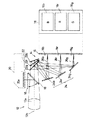
以下、図示実施例に基づいて本発明を説明する。図1において、光学系を概略的に示すスチルビデオカメラには、その前方に被写体の光学像を形成するための結像光学系12a等を有する結像光学系12が設けられている。結像光学系12の後方には、本発明に係る三色分解光学装置14が設けられ、この分解光学系14の後方の所定位置には、電子現像型記録媒体16が配設されている。撮像光学系12と三色分解光学装置14との間には、クィックリターンミラー18が設けられ、クィックリターンミラー18の上方には、ファインダ光学系20のピント板20aが配設されている。クィックリターンミラー18は、通常はダウン位置(実線で示される傾斜状態)にあり、撮像光学系12を通過した光をファインダ光学系20へ導いているが、撮影動作時には、カメラのシステムコントロール回路(図示せず)の制御により、上方のアップ位置(破線で示される退避状態)へ回動される。
【0014】
三色分解光学装置14は、クィックリターンミラー18の後方に設けられたダイクロイックミラー光学系22と、このダイクロイックミラー光学系22と電子現像型記録媒体16との間に設けられた反射ミラー光学系24とを備える。
【0015】
図1及び図2に示すように、ダイクロイックミラー光学系22は、結像光学系12により形成された被写体像をR(赤)、G(緑)及びB(青)の三原色光成分に色分解する。この光学系22は、結像光学系12の光軸12bに沿って配置された三枚のダイクロイックミラー22g、22r、22bを有する。これら三枚のダイクロイックミラーのうち、結像光学系12側に配置された第一ダイクロイックミラー22gは、結像光学系12から入射された被写体像のうち、G成分26gを反射し、R成分とB成分を透過する。第一ダイクロイックミラー22gの後方に配置された第二ダイクロイックミラー22rは、第一ダイクロイックミラー22gを透過したR成分26rを反射し、B成分を透過する。第二ダイクロイックミラー22rの後方に配置された第三ダイクロイックミラー22bは、第一、第二のダイクロイックミラー22g、22rを透過したB成分26bを反射する。これらダイクロイックミラー22g、22r、22bは、反射されたG、R及びB成分を所定の方向(図示の実施例では光軸12bの下方)のそれぞれ異なる中継位置へ反射するように、光軸12bに対して所定の傾きをなしている。更に、第二(赤反射)と第三(青反射)ダイクロイックミラー22r、22bは、それらで反射された色光成分が、その前方に配置されたダイクロイックミラーを透過する位置及び傾斜状態に配設されている。
【0016】
三色分解光学装置14の反射ミラー光学系24は、ダイクロイックミラー光学系22によるBRG成分の中継位置にそれぞれ配設された第一、第二及び第三の反射ミラー24g、24r、24bを有する。これら三つの反射ミラーは、ダイクロイックミラー光学系22で反射されたG、R及びB成分の光路を互いに略平行に整列させて記録媒体16方向へ反射させる傾斜状態に配置されている。これらの反射ミラー24g、24r、24bは、全反射ミラーであることが好ましいが、ハーフミラーとして透過光を別の用途に用いることも可能である。
【0017】
記録媒体16のG、R及びBのそれぞれの記録領域16g、16r、16bは、光軸12bに対して紙面上で直交する同一面内に配列されている。また、結像光学系12と三色分解光学装置14とは、反射ミラー24g、24r、24bで反射されたG、R及びB成分が、記録媒体16の各記録領域16g、16r、16bに結像するように設定されている。
【0018】
カメラ10のクィックリターンミラー18がアップ位置に移動し、シャッタ(図示せず)が解放された撮影動作時における三色分解光学装置14の作用について説明する。結像光学系12で形成された被写体像のうち、G成分26gは、第一ダイクロイックミラー22gで反射され、次いで第一反射ミラー24gで反射されて記録媒体16のG記録領域16gに結像される。また、R成分26rは、第一ダイクロイックミラー22gを透過して第二ダイクロイックミラー22rで反射される。この反射されたR成分26rは、再び第一ダイクロイックミラー22gを透過し、第二反射ミラー24rで反射されて記録媒体16のR記録領域16rに結像される。B成分26bは、第一と第二のダイクロイックミラー22g、22rを透過して第三ダイクロイックミラー22bで反射される。この反射されたB成分26bは、第二と第一のダイクロイックミラーを再び透過した後、第三反射ミラー24bで反射されて記録媒体16のB記録領域16bに結像される。
【0019】
電子現像型記録媒体16は、例えば特開平5−2280号公報に開示されたように、所定の電圧を印加することにより活性化され、露光量に応じた画像情報が電子的に記録保持される形式である。この記録媒体16は、少なくともカメラのシャッタが解放されている間、システムコントロール回路の制御により活性化される。この状態で露光されることにより、記録媒体16の記録領域には、結像されたG、R及びBの像が現像される。現像されたG、R及びBの像に、カメラに内蔵された公知の走査機構及び画像処理系(共に図示せず)等による適宜な処理を施すことにより、電気的に合成されたカラー画像が得られる。記録媒体16上のG、R及びBの像は同一平面上に整列されているので、その走査は容易である。
【0020】
図3は、三色分解光学装置14の各ミラーの位置座標の関係を示す。図において、ダイクロイックミラー光学系22に対する入射光の光軸をX軸とし、X軸に対し直交しかつG、R及びBの像の結像面を含む仮想平面(紙面に対して垂直な平面)においてX軸に対して紙面上で直交する方向をY軸とする。X軸と仮想平面との交点をXY座標原点(0,0)とし、X軸と各ダイクロイックミラー22g、22r、22bとの交点、即ちダイクロイックミラー光学系22におけるG、R及びBの像の反射位置の座標をそれぞれ(x00,0)、(x01,0)、(x02,0)とする。また、B、R及びG像の結像位置の座標をそれぞれ(0,P0 )、(0,P0 +P)、(0,P0 +2P)とする。この結像位置に対して平行をなす各反射ミラー24b、24r、24gによるB、R及びG像の反射位置の中央の座標は、それぞれ(x1 ,P0 )、(x2 ,P0 +P)、(x3 ,P0 +2P)と表せる。これら各座標成分の間には、次式1の関係がある。
【0021】
【式1】
[(x00−x1 )2 +(P0 )2 ]1/2 +|x1 |
=[(x00−x2 )2 +(P0 +P)2 ]1/2 +|x1 |
=[(x00−x3 )2 +(P0 +2P)2 ]1/2 +|x1 |
【0022】
ここでダイクロイックミラー光学系22におけるG、R及びBの像の反射位置のX座標x00、x01、x02と、結像位置のY座標成分P、P0 、2Pとは予め定めることができる。従って、これらx00、x01、x02、P、P0 、2Pから、上式によって各反射ミラー24b、24r、24gの反射位置のX座標成分x1 、x2 、x3 を求めることができる。
【0023】
上述のように反射位置を定められた三つの反射ミラー24g、24r、24bの傾斜状態の調整は、公知の三点調整法を用いることができる。この場合、反射ミラー24g、24r、24bとして三つの分岐ミラーを用いることが好ましい。仮にダイクロイックミラーの固定精度が低ければ、電子現像型記録媒体16上のG、R及びBの像の上下方向(Y方向)の位置が変化するが、三つのミラー24g、24r、24bの調整により各像のピント位置を設定できる。更に、G、R及びBの像の上下位置の変化は、カラー画像の電気的合成時に公知の画像処理法によって補正することも可能である。
【0024】
本実施例における三色分解装置14には、従来のようなプリズムを全く使用せず、光路が通過する光学材料は互いに独立した三つのダイクロイックミラー22b、22r、22gのみである。従って、収差が小さく、高解像度の画像が得られる。また、プリズムを排したことにより、各ミラー22g、22r、22b及び24g、24r、24bには、個々に位置調整機構を取り付けることも可能である。そのため、加工精度が低くても、各ミラーの調整により正確な結像位置設定が可能である。三つのダイクロイックミラー22g、22r、22bは、ペリクル(pellicle)ミラーや、非常に薄いガラス板にダイクロイック蒸着を施したミラーを使用できる。ダイクロイックミラー22g、22r、22bを形成するガラス板の薄さは、要求されるカラー画像の解像度に応じて定められる。勿論、ガラス板が薄いほど、高解像度の画像が得られる。
【0025】
以上の実施例では、前方から順に、G、R、B成分をそれぞれ反射するダイクロイックミラー22g、22r、22bを配置したが、この配置順序は変更可能である。最も比視感度の高いG用のダイクロイックミラー22gを最前方に配置すると、緑色光は収差の影響を受けないので最も好ましいが、反面、Gのバンドパス特性を有するダイクロイック膜を必要とする。また、最終ミラーは厚いミラーとして平面性を高くすることが容易であるから、最終ミラーの高い平面性とGの高い比視感度を考慮すれば、G用のミラーを最後方に配置することも考えられる。G用のミラーを最後方に配置すれば、Gのバンドパス特性を有するダイクロイック膜が不要になるという利点がある。
【0026】
図4は本発明の第二実施例を示す。本実施例の三色分解光学装置のダイクロイックミラー光学系22には、第一実施例の三つの独立したダイクロイックミラー22g、22r、22bに代えて、三つのダイクロイックミラーを一体的に形成したプリズム28が用いられている。この実施例では、プリズム28中の光路長を抑制するために、図示のように第一のダイクロイックミラー22gを空気との境界面に設けることが好ましい。カラー画像の解像度の要求がさほど厳しくない場合には、本実施例を適用することが可能である。しかしながら、本実施例においても、プリズム28を出射した後の光路は、第一実施例と同様に反射ミラー光学系24を経て記録媒体16に至るまで気体媒質中のみを通過する。従って、従来例に比べれば収差を小さくすることができる。また、プリズム28中には複雑な光路を形成する必要がないので、従来例のプリズムに比べて要求される加工精度が緩和され、製造コストも安価である。更に、反射ミラー光学系24は、プリズム28と独立しているので、反射ミラー光学系24の個々のミラーに位置調整機構を取り付けることも可能である。
【0027】
次に図5、図6は、フランジバックの短い結像光学系12aを使用する場合に好適な実施例である。スぺーサ30によって第一、第二、第三のダイクロイックミラー22g、22r、22bを所定の位置関係で固定したダイクロイックミラー光学系22Mは、クイックリターンミラー18の下方において図の上下に移動可能である。この可動ダイクロイックミラーユニット22Mは、結像光学系12aの光軸12bから下方に退避した退避位置(図5)と、結像光学系12aの光軸内に進出する進出位置(図6)との間を移動可能であり、この移動は、クイックリターンミラー18の動作と連動して行なわれる。すなわち、クイックリターンミラー18が図5に示す観察位置にあるときには、可動ダイクロイックミラーユニット22Mはクイックリターンミラー18と干渉しないように光軸12bから退避し、クイックリターンミラー18が退避位置に跳ね上がると、その動作に連動して光軸12b内に進出する。3枚のミラー24b、24r、24gを有する反射ミラー光学系24は、可動ダイクロイックミラーユニット22Mが光軸12b内に進出したとき、可動ダイクロイックミラーユニット22Mと図1と同様の光学系を構成するように位置が定められている。よって、この実施例によれば、フランジバックの短い結像光学系12を用いた一眼レフタイプのカラー分解カメラに本発明を適用することができる。可動ダイクロイックミラーユニット22Mの退避方向は、紙面と垂直な方向としてもよい。また、可動ダイクロイックミラーユニット22Mだけでなく、反射ミラー光学系24を可動ダイクロイックミラーユニット22Mと一体に移動させる構成としてもよいが、図示例の方が可動部分が小さいので、カメラの小型化ができる。
【0028】
以上は、三色分解光学装置に本発明を適用した実施例を説明したものであるが、本発明はより広く、二色分解光学装置(二板式)についても適用可能である。この場合には、ダイクロイックミラーと反射ミラーをそれぞれ2枚ずつ配置すればよい。
【0029】
本発明は上述した実施例に限定されるものではなく、様々な変形が可能である。例えば、上述した実施例では本発明の三色分解装置をスチルビデオカメラに適用して説明したが、それに限定されるものではなく、他の形式の三原色分解カメラ、カラー複写機等の高解像度カラー撮像装置に広く適用できる。
【0030】
また、三色分解装置の反射ミラー24g、24r、24bは、ダイクロイックミラー光学系22からの三つの色光の光路を互いに略平行に整列させる傾斜状態に定められていればよく、その反射光の光路が導かれる対象は電子現像型記録媒体16に限定されない。従って、三つの色光の記録媒体としては、カラー画像を電気的に合成するものに限らず、光学的に合成するものであってもよい。
【0031】
【発明の効果】
以上のように本発明の色分解装置によれば、ガラス媒質等の光学材料中の光路長を抑制できるので、収差の小さい高解像度な光学像が得られる。また、従来のような分解光学系と複雑な光路とを一体的に形成したプリズムを排したので、加工精度の条件が緩和され、装置構成が単純で安価である。更に、異なる色光の光路が略平行に整列されているので、各色像の位置を整列可能である。
【図面の簡単な説明】
【図1】本発明の第一実施例の三色分解装置を有するスチルビデオカメラの光学系を模式的に示す図であり、記録媒体の平面図を併せて示す図である。
【図2】図1の三色分解装置におけるダイクロイックミラー光学系の拡大図である。
【図3】図1の三色分解装置の各ミラーの位置座標を示す概略的な光路図である。
【図4】本発明の第二実施例の三色分解装置のプリズムを示す側面図である。
【図5】本発明の別の実施例を示す、一眼レフカメラの観察中の図である。
【図6】図5の一眼レフカメラの撮影中の図である。
【符号の説明】
12 結像光学系
22 ダイクロイックミラー光学系
22M 可動ダイクロイックミラーユニット
22g 緑反射ダイクロイックミラー(第一のダイクロイックミラー)
22r 赤反射ダイクロイックミラー(第二のダイクロイックミラー)
22b 青反射ダイクロイックミラー(第三のダイクロイックミラー)
24 反射ミラー光学系
24g 第一の反射ミラー
24r 第二の反射ミラー
24b 第三の反射ミラー
26g 緑色光(第一の色光)
26r 赤色光(第二の色光)
26b 青色光(第三の色光)
28 プリズム[0001]
【Technical field】
The present invention relates to a color separation optical apparatus and a single-lens reflex type color separation optical apparatus that are provided in a high-resolution color image pickup apparatus such as a still video camera or a color copying machine, for color separation of an optical image of a subject.
[0002]
[Prior art and its problems]
2. Description of the Related Art A high-resolution imaging apparatus is known that forms three primary color images of red, green, and blue on a monochrome recording medium and forms a color image by optically or electrically combining these three primary color images. Here, as a three-color separation optical system for obtaining a three-primary color image, one using one or a plurality of prisms is known.
[0003]
For example, Japanese Patent Laid-Open No. 1-319384 discloses an optical system in which a dichroic prism and two optical path forming prisms arranged symmetrically with respect to the optical axis of incident light of the dichroic prism are disclosed. Here, the dichroic prism includes dichroic mirrors of red reflection and blue reflection orthogonal to each other so as to separate incident light into three primary colors of red, green, and blue. Each optical path forming prism has a total reflection surface for reflecting one of red light and blue light from the dichroic prism. In this configuration, of the incident light to the dichroic prism, green light passes through the two dichroic mirrors and forms an image at the green image position on the imaging surface. Further, red light and blue light are reflected by the corresponding dichroic mirrors in directions orthogonal to the optical axis of the incident light and different from each other by 180 degrees, and then reflected by the total reflection surface of the corresponding optical path forming prism. Reflected in a direction parallel to the axis. The reflected red light and blue light pass through the corresponding optical path forming prism in parallel with the optical path of the green light, and as a result, the optical path length is extended. As a result, the reflected red light and blue light approach the position of the green image on the imaging surface. An image is formed at each of the red image position and the blue image position.
[0004]
Japanese Patent Laid-Open No. 6-167603 discloses a three-color separation prism in which the dichroic prism of Japanese Patent Laid-Open No. 1-319384 and two optical path forming prisms are integrally formed. However, in this three-color separation prism, two total reflection surfaces for extending the optical path length of green light are added in the prism for the purpose of equalizing the optical path length of each color light in the prism. That is, the green light transmitted through the two dichroic mirrors is reflected by one total reflection surface in a direction perpendicular to the optical axis of the incident light and different from the reflection direction of red and blue light by 90 degrees, and then the other Is reflected in a direction parallel to the optical axis. As a result of the extension of the optical path length of the green light, the green image on the imaging plane is not aligned with the red image and the blue image, but has a staggered arrangement.
[0005]
In the conventional optical system of this type, the optical path length in the prism is intentionally extended in order to adjust the optical path length of each color light and the imaging position, so that the optical path length in the glass medium becomes long, and Incident light is refracted. As a result, large spherical aberration occurs, and it is difficult to form a highly accurate image. Further, when the optical path length of the green light is extended as in JP-A-6-167603, the green image position on the imaging plane is not aligned with the red image position and the blue image position. Image scanning becomes complicated.
[0006]
Further, in the conventional optical system, since all the reflection surfaces of the dichroic mirror surface for color separation and the total reflection surface for light path guidance are formed in the prism, the image formation position of each color light image is It depends greatly on the processing accuracy of the prism. Therefore, high processing accuracy is required for the prism, and its manufacturing cost is also expensive.
[0007]
OBJECT OF THE INVENTION
The object of the present invention is to reduce the optical path length in an optical material such as a glass medium, relax the required processing accuracy, and align each color image position. To provide an apparatus.
[0008]
SUMMARY OF THE INVENTION
The present invention is a color separation optical apparatus for color-separating incident light into at least two color lights, which are sequentially arranged along the optical axis of the incident light and each reflect a plurality of dichroic mirrors; The plurality of dichroic mirrors reflect the corresponding colored light respectively to different relay positions in the gas medium, and the incident light and the reflected light from the rear dichroic mirror are arranged in front of the rear dichroic mirror. A plurality of reflecting mirrors respectively disposed at the plurality of relay positions corresponding to the plurality of dichroic mirrors; and the plurality of reflecting mirrors from the plurality of dichroic mirrors. Are arranged at positions where optical paths of different color lights are aligned substantially parallel to each other. It is set to.
[0009]
According to one aspect of the present invention, a plurality of dichroic mirrors are independent optical members for the purpose of suppressing the optical path length in the optical member. Alternatively, the plurality of dichroic mirrors may be formed as an integral prism. In this case, it is preferable that the reflection surface of the first dichroic mirror is formed on the boundary surface with air.
[0010]
The color separation device according to the present invention is disposed in front of a plurality of dichroic mirrors for the purpose of forming optical images of optical paths of a plurality of color lights aligned by a plurality of reflection mirrors at different positions on the same plane. An imaging optical system may be further provided.
[0011]
For example, according to the three-color separation optical device of the present invention, the first color light out of the incident light is reflected by the first dichroic mirror. The second color light is transmitted through the first dichroic mirror, reflected by the second dichroic mirror, and transmitted through the first dichroic mirror. The third color light passes through the first and second dichroic mirrors, is reflected by the third dichroic mirror, and passes through the second and first dichroic mirrors. Accordingly, the three color lights are all guided to the incident side of the first dichroic mirror without being reflected by other than the dichroic mirror, that is, without passing through a complicated optical path. The optical paths of the three color lights thus guided are emitted from the first dichroic mirror and then reflected by the individual reflecting mirrors. Therefore, the optical paths of the three color lights are transmitted through an optical member such as a prism. And are aligned substantially parallel to each other.
[0012]
In addition, the color separation device of the present invention includes an embodiment applicable to a photographing lens having a short flange back in a single-lens reflex type device including a quick return mirror. In this embodiment, the imaging optical system is located behind the imaging optical system, and is always located at the observation position for guiding the subject image to the finder optical system, and at the time of shooting, the quick return is located at the retracted position from the optical path. In conjunction with the movement of the quick mirror, a movable dichroic mirror unit that advances into the optical path when the quick return mirror moves to the retracted position and retracts from the optical path when the quick return mirror moves to the observation position; And a plurality of dichroic mirrors arranged sequentially along the optical axis of the incident light and reflecting different color lights, respectively, and the plurality of dichroic mirrors respectively reflect the corresponding color lights to different relay positions in the gas medium. And incident light and reflected light from the rear dichroic mirror are The movable dichroic mirror unit is disposed at the plurality of relay positions corresponding to the plurality of dichroic mirrors when the movable dichroic mirror unit is positioned in the optical path. A plurality of reflection mirrors; the plurality of reflection mirrors are arranged at positions where the optical paths of the different color lights from the plurality of dichroic mirrors are aligned substantially in parallel with each other; and the optical paths of the plurality of reflection mirrors And a monochrome recording medium disposed on a single orthogonal plane.
[0013]
DETAILED DESCRIPTION OF THE INVENTION
Hereinafter, the present invention will be described based on illustrated embodiments. In FIG. 1, a still video camera schematically showing an optical system is provided with an imaging
[0014]
The three-color separation
[0015]
As shown in FIGS. 1 and 2, the dichroic mirror
[0016]
The reflection mirror
[0017]
The
[0018]
The operation of the three-color separation
[0019]
The electro-developing
[0020]
FIG. 3 shows the positional coordinate relationship of each mirror of the three-color separation
[0021]
[Formula 1]
[(X 00 −x 1 ) 2 + (P 0 ) 2 ] 1/2 + | x 1 |
= [(X 00 −x 2 ) 2 + (P 0 + P) 2 ] 1/2 + | x 1 |
= [(X 00 −x 3 ) 2 + (P 0 + 2P) 2 ] 1/2 + | x 1 |
[0022]
Here, the X coordinates x 00 , x 01 , x 02 of the reflection positions of the G, R, and B images in the dichroic mirror
[0023]
A known three-point adjustment method can be used to adjust the tilt state of the three
[0024]
The three-
[0025]
In the above embodiment, the
[0026]
FIG. 4 shows a second embodiment of the present invention. In the dichroic mirror
[0027]
Next, FIGS. 5 and 6 show an embodiment suitable when the imaging
[0028]
The above is a description of an embodiment in which the present invention is applied to a three-color separation optical apparatus. However, the present invention is more broadly applicable to a two-color separation optical apparatus (two-plate type). In this case, two dichroic mirrors and two reflection mirrors may be arranged.
[0029]
The present invention is not limited to the above-described embodiments, and various modifications are possible. For example, in the above-described embodiments, the three-color separation device of the present invention has been described as applied to a still video camera. However, the present invention is not limited to this, and other types of three-color separation cameras, color copiers, etc. Widely applicable to imaging devices.
[0030]
The reflection mirrors 24g, 24r, and 24b of the three-color separation device need only be set in an inclined state in which the optical paths of the three color lights from the dichroic mirror
[0031]
【The invention's effect】
As described above, according to the color separation device of the present invention, since the optical path length in an optical material such as a glass medium can be suppressed, a high-resolution optical image with small aberration can be obtained. Further, since the prism in which the conventional splitting optical system and the complicated optical path are integrally formed is eliminated, the processing accuracy condition is relaxed, and the apparatus configuration is simple and inexpensive. Furthermore, since the optical paths of the different color lights are aligned substantially in parallel, the positions of the respective color images can be aligned.
[Brief description of the drawings]
FIG. 1 is a diagram schematically illustrating an optical system of a still video camera having a three-color separation device according to a first embodiment of the present invention, and a diagram illustrating a plan view of a recording medium.
2 is an enlarged view of a dichroic mirror optical system in the three-color separation device of FIG. 1. FIG.
3 is a schematic optical path diagram showing position coordinates of each mirror of the three-color separation device in FIG. 1; FIG.
FIG. 4 is a side view showing a prism of the three-color separation device according to the second embodiment of the present invention.
FIG. 5 is a diagram of a single-lens reflex camera during observation showing another embodiment of the present invention.
6 is a diagram during shooting of the single-lens reflex camera of FIG. 5. FIG.
[Explanation of symbols]
12 Imaging
22r Red reflective dichroic mirror (second dichroic mirror)
22b Blue reflective dichroic mirror (third dichroic mirror)
24 reflection mirror optical system 24g
26r Red light (second color light)
26b Blue light (third color light)
28 Prism
Claims (6)
入射光の光軸に沿って順次に配設され、それぞれ異なる色光を反射する複数のダイクロイックミラー;
これら複数のダイクロイックミラーは、対応する色光を気体媒質中の異なる中継位置へそれぞれ反射し、かつ後方のダイクロイックミラーについての入射光及び反射光が、該後方のダイクロイックミラーより前方に配置されたダイクロイックミラーを透過する位置に配置されていること;
これら複数のダイクロイックミラーに対応させて上記複数の中継位置にそれぞれ配設された複数の反射ミラー;及び、
これら複数の反射ミラーは、上記複数のダイクロイックミラーからの異なる色光の光路を互いに略平行に整列させる位置に配置されていること;
を特徴とする色分解光学装置。A color separation optical device for separating incident light into at least two color lights,
A plurality of dichroic mirrors arranged sequentially along the optical axis of incident light and reflecting different color lights;
The plurality of dichroic mirrors reflect the corresponding colored light respectively to different relay positions in the gas medium, and the incident light and the reflected light from the rear dichroic mirror are arranged in front of the rear dichroic mirror. Placed in a position where it passes through;
A plurality of reflecting mirrors respectively disposed at the plurality of relay positions corresponding to the plurality of dichroic mirrors; and
The plurality of reflecting mirrors are arranged at positions where optical paths of different colored lights from the plurality of dichroic mirrors are aligned substantially parallel to each other;
A color separation optical device.
入射光の光軸に沿って順次に配設され、それぞれ第一、第二及び第三の色光を反射する第一、第二及び第三のダイクロイックミラー;
これら三つのダイクロイックミラーは、対応する色光を気体媒質中の三つの異なる中継位置へそれぞれ反射し、かつ第二及び第三のダイクロイックミラーについての入射光及び反射光がそれらの前方に配置された上記ダイクロイックミラーを透過する位置に配設されていること;
これら三つのダイクロイックミラーに対応させて上記三つの中継位置にそれぞれ配設された三つの反射ミラー;及び、
これら三つの反射ミラーは、上記三つのダイクロイックミラーからの上記三つの色光の光路を互いに略平行に整列させる位置に配置されていること;
を特徴とする色分解光学装置。A color separation optical device for separating incident light into at least three color lights,
First, second and third dichroic mirrors sequentially disposed along the optical axis of the incident light and reflecting the first, second and third color lights, respectively;
These three dichroic mirrors respectively reflect the corresponding colored light to three different relay positions in the gas medium, and the incident light and reflected light for the second and third dichroic mirrors are arranged in front of them. Be disposed at a position where it passes through the dichroic mirror;
Three reflecting mirrors respectively disposed at the three relay positions corresponding to the three dichroic mirrors; and
The three reflecting mirrors are arranged at positions where the optical paths of the three colored lights from the three dichroic mirrors are aligned substantially parallel to each other;
A color separation optical device.
この結像光学系の後方にあって、常時は被写体像をファインダ光学系に導く観察位置に位置し、撮影時は光路からの退避位置に位置するクイックリターンミラー;
このクイックミラーの動きに連動して、該クイックリターンミラーが退避位置に移動したとき光路内に進出し、観察位置に移動したとき光路から退避する可動ダイクロイックミラーユニット;
この可動ダイクロイックミラーユニットは、入射光の光軸に沿って順次に配設され、それぞれ異なる色光を反射する複数のダイクロイックミラーを有し、これら複数のダイクロイックミラーは、対応する色光を気体媒質中の異なる中継位置へそれぞれ反射し、かつ後方のダイクロイックミラーについての入射光及び反射光が、該後方のダイクロイックミラーより前方に配置されたダイクロイックミラーを透過する位置に配置されていること;
上記可動ダイクロイックミラーユニットが光路内に位置するときのその複数のダイクロイックミラーに対応させて上記複数の中継位置にそれぞれ配設された複数の反射ミラー;
これら複数の反射ミラーは、上記複数のダイクロイックミラーからの異なる色光の光路を互いに略平行に整列させる位置に配置されていること;及び、
これらの複数の反射ミラーの光路に直交する単一の平面上にそれぞれ配設されたモノクロ記録媒体;
を備えることを特徴とする色分解光学装置。Imaging optics;
A quick return mirror that is located behind the imaging optical system and is normally located at an observation position for guiding the subject image to the finder optical system, and at a retracted position from the optical path during photographing;
In conjunction with the movement of the quick mirror, a movable dichroic mirror unit that advances into the optical path when the quick return mirror moves to the retracted position and retracts from the optical path when moved to the observation position;
The movable dichroic mirror unit is sequentially arranged along the optical axis of incident light, and has a plurality of dichroic mirrors that reflect different color lights, and the plurality of dichroic mirrors transmit the corresponding color light in a gas medium. Reflected to different relay positions, and incident light and reflected light from the rear dichroic mirror are disposed at positions where they pass through the dichroic mirror disposed in front of the rear dichroic mirror;
A plurality of reflecting mirrors respectively disposed at the plurality of relay positions corresponding to the plurality of dichroic mirrors when the movable dichroic mirror unit is located in the optical path;
The plurality of reflecting mirrors are arranged at positions where optical paths of different colored lights from the plurality of dichroic mirrors are aligned substantially parallel to each other; and
Monochrome recording media respectively disposed on a single plane orthogonal to the optical paths of the plurality of reflecting mirrors;
A color separation optical device comprising:
Priority Applications (2)
| Application Number | Priority Date | Filing Date | Title |
|---|---|---|---|
| JP16906095A JP3629068B2 (en) | 1995-07-04 | 1995-07-04 | Color separation optical device |
| US08/675,159 US5920347A (en) | 1995-07-04 | 1996-07-03 | Optical color separation system utilizing dichroic mirrors |
Applications Claiming Priority (1)
| Application Number | Priority Date | Filing Date | Title |
|---|---|---|---|
| JP16906095A JP3629068B2 (en) | 1995-07-04 | 1995-07-04 | Color separation optical device |
Publications (2)
| Publication Number | Publication Date |
|---|---|
| JPH0923440A JPH0923440A (en) | 1997-01-21 |
| JP3629068B2 true JP3629068B2 (en) | 2005-03-16 |
Family
ID=15879606
Family Applications (1)
| Application Number | Title | Priority Date | Filing Date |
|---|---|---|---|
| JP16906095A Expired - Fee Related JP3629068B2 (en) | 1995-07-04 | 1995-07-04 | Color separation optical device |
Country Status (2)
| Country | Link |
|---|---|
| US (1) | US5920347A (en) |
| JP (1) | JP3629068B2 (en) |
Families Citing this family (14)
| Publication number | Priority date | Publication date | Assignee | Title |
|---|---|---|---|---|
| JPH1188733A (en) * | 1997-09-05 | 1999-03-30 | Olympus Optical Co Ltd | Electronic image pickup device |
| JP3460643B2 (en) * | 1999-09-29 | 2003-10-27 | ミノルタ株式会社 | Digital camera |
| US8134637B2 (en) * | 2004-01-28 | 2012-03-13 | Microsoft Corporation | Method and system to increase X-Y resolution in a depth (Z) camera using red, blue, green (RGB) sensing |
| JP2007526453A (en) * | 2004-01-28 | 2007-09-13 | カネスタ インコーポレイテッド | Single chip red, green, blue, distance (RGB-Z) sensor |
| US20070081252A1 (en) * | 2005-08-04 | 2007-04-12 | Shu-I Lin | Single panel reflective-type color optical engine |
| US8139142B2 (en) | 2006-06-01 | 2012-03-20 | Microsoft Corporation | Video manipulation of red, green, blue, distance (RGB-Z) data including segmentation, up-sampling, and background substitution techniques |
| IT1390779B1 (en) * | 2008-07-03 | 2011-09-23 | St Microelectronics Srl | PHOTOVOLTAIC DEVICE WITH CONCENTRATION AND SPECTAL DISTRIBUTION OF CAPTATA RADIATION |
| US8376551B2 (en) * | 2010-02-25 | 2013-02-19 | Corning Incorporated | Illumination system for laser projection |
| CN102169233B (en) * | 2011-01-26 | 2014-07-23 | 阮双琛 | Tunable light splitting and combing device and optical application system |
| US9375172B2 (en) * | 2011-11-07 | 2016-06-28 | Corning Incorporated | Apparatus for substance detection |
| US9258468B2 (en) * | 2012-02-15 | 2016-02-09 | Fluxdata, Inc. | Method and apparatus for separate spectral imaging and sensing |
| US9257478B2 (en) | 2012-05-22 | 2016-02-09 | The Regents Of The University Of California | Spatially resolved spectral-imaging device |
| US9638988B2 (en) | 2013-12-12 | 2017-05-02 | Corning Incorporated | Light multiplexer with color combining element |
| WO2017001878A1 (en) * | 2015-07-02 | 2017-01-05 | Fulvio Jacocagni | High definition multispectral-multi-chanel imaging camera system |
Family Cites Families (13)
| Publication number | Priority date | Publication date | Assignee | Title |
|---|---|---|---|---|
| BE760069A (en) * | 1969-12-10 | 1971-05-17 | Western Electric Co | SINGLE TUBE COLOR TELEVISION CAMERA WITH PHASE |
| US4654698A (en) * | 1984-06-18 | 1987-03-31 | Eastman Kodak Company | Color sensor using dichroic mirrors to displace components |
| JPS6290087A (en) * | 1985-10-15 | 1987-04-24 | Minolta Camera Co Ltd | Electronic still camera of single-lens peflex type |
| US4709144A (en) * | 1986-04-02 | 1987-11-24 | Hewlett-Packard Company | Color imager utilizing novel trichromatic beamsplitter and photosensor |
| JPS63301067A (en) * | 1987-05-30 | 1988-12-08 | Asahi Optical Co Ltd | Color separating mechanism for color copying machine |
| JPS6468190A (en) * | 1987-09-09 | 1989-03-14 | Victor Company Of Japan | Three-color separation optical system |
| US4964696A (en) * | 1988-01-12 | 1990-10-23 | Asahi Kogaku Kogyo Kabushiki Kaisha | Color separating optical apparatus |
| JPH01319384A (en) * | 1988-06-21 | 1989-12-25 | Victor Co Of Japan Ltd | Color image pickup device |
| US5424156A (en) * | 1990-07-06 | 1995-06-13 | Dai Nippon Printing Co., Ltd. | Electrostatic information recording medium and method of recording and reproducing electrostatic information |
| JP3046649B2 (en) * | 1990-07-06 | 2000-05-29 | 大日本印刷株式会社 | Electrostatic information recording medium and electrostatic information recording / reproducing method |
| JP3023152B2 (en) * | 1990-08-23 | 2000-03-21 | 株式会社トプコン | Color separation optics |
| JPH06167603A (en) * | 1992-09-29 | 1994-06-14 | Dainippon Printing Co Ltd | Three color separation prism |
| US5621460A (en) * | 1994-10-11 | 1997-04-15 | Lockheed Martin Corporation | Optical differentiation between plants and background utilizing a single CCD camera |
-
1995
- 1995-07-04 JP JP16906095A patent/JP3629068B2/en not_active Expired - Fee Related
-
1996
- 1996-07-03 US US08/675,159 patent/US5920347A/en not_active Expired - Fee Related
Also Published As
| Publication number | Publication date |
|---|---|
| JPH0923440A (en) | 1997-01-21 |
| US5920347A (en) | 1999-07-06 |
Similar Documents
| Publication | Publication Date | Title |
|---|---|---|
| JP3629068B2 (en) | Color separation optical device | |
| EP0307203B1 (en) | Tri-color separating optical system | |
| US8773645B2 (en) | Distance measuring device and imaging device | |
| US6698893B2 (en) | Optical device suitable for separating and synthesizing light | |
| US5251068A (en) | Objective lens having a filter | |
| JP3478687B2 (en) | Compound eye imaging device | |
| JPH0350492Y2 (en) | ||
| US7287854B2 (en) | Ophthalmic photography apparatus | |
| US20080198472A1 (en) | Projection type image display apparatus | |
| CA1060240A (en) | Television camera optical system | |
| US20060250697A1 (en) | Image display apparatus and camera | |
| US5790190A (en) | Electronic development type image pickup device | |
| JPH10133306A (en) | Three-dimensional image pickup device | |
| JP3605159B2 (en) | Camera color separation optics | |
| JP2518036B2 (en) | Telecine camera | |
| JP3435281B2 (en) | Electro-developing imaging device | |
| JPH0554779B2 (en) | ||
| JPH06167603A (en) | Three color separation prism | |
| JPH0855889A (en) | Image combiner | |
| JPH07307951A (en) | Image input device | |
| JP2644232B2 (en) | Exposure equipment for color copiers | |
| JP2003066316A (en) | Zoom lens device, optical device and projector using the same | |
| JPH08334829A (en) | Optical system for camera | |
| JPH0545750A (en) | Stereoscopic camera | |
| JPH05127224A (en) | Photographing device |
Legal Events
| Date | Code | Title | Description |
|---|---|---|---|
| A977 | Report on retrieval |
Free format text: JAPANESE INTERMEDIATE CODE: A971007 Effective date: 20040929 |
|
| TRDD | Decision of grant or rejection written | ||
| A01 | Written decision to grant a patent or to grant a registration (utility model) |
Free format text: JAPANESE INTERMEDIATE CODE: A01 Effective date: 20041207 |
|
| A61 | First payment of annual fees (during grant procedure) |
Free format text: JAPANESE INTERMEDIATE CODE: A61 Effective date: 20041210 |
|
| R150 | Certificate of patent or registration of utility model |
Free format text: JAPANESE INTERMEDIATE CODE: R150 |
|
| LAPS | Cancellation because of no payment of annual fees |