JP3628811B2 - Magnetic field sensing system - Google Patents
Magnetic field sensing system Download PDFInfo
- Publication number
- JP3628811B2 JP3628811B2 JP17468596A JP17468596A JP3628811B2 JP 3628811 B2 JP3628811 B2 JP 3628811B2 JP 17468596 A JP17468596 A JP 17468596A JP 17468596 A JP17468596 A JP 17468596A JP 3628811 B2 JP3628811 B2 JP 3628811B2
- Authority
- JP
- Japan
- Prior art keywords
- output
- magnetic field
- vector
- circuit
- threshold value
- Prior art date
- Legal status (The legal status is an assumption and is not a legal conclusion. Google has not performed a legal analysis and makes no representation as to the accuracy of the status listed.)
- Expired - Fee Related
Links
Images
Classifications
-
- G—PHYSICS
- G01—MEASURING; TESTING
- G01R—MEASURING ELECTRIC VARIABLES; MEASURING MAGNETIC VARIABLES
- G01R33/00—Arrangements or instruments for measuring magnetic variables
- G01R33/02—Measuring direction or magnitude of magnetic fields or magnetic flux
- G01R33/0206—Three-component magnetometers
Landscapes
- Physics & Mathematics (AREA)
- Condensed Matter Physics & Semiconductors (AREA)
- General Physics & Mathematics (AREA)
- Magnetic Resonance Imaging Apparatus (AREA)
- Measuring Magnetic Variables (AREA)
- Emergency Alarm Devices (AREA)
Description
【0001】
【産業上の利用分野】
本願発明は、磁界センサに関し、より詳細には、電子装置と共に用いられ且つ感知電磁界の強さに応じて該電子装置の動作を制御する磁界センサに関する。
【0002】
【従来の技術】
磁気共鳴映像(MRI)システムには、その直ぐ近傍に強烈な磁界を作り出す大型の磁気コイル構造体が包含されている。そのコイル構造体の開口部内部(ここに患者が配置される)では、磁界強度が2,000ガウス〜15,000ガウスの範囲にあることがある。磁界強度は、コイル構造体からの距離が増えるにつれ急速に減少するが、MRIの無線周波数(RF)囲い内部にはやはり強い残留磁界が存在することが知られている。この理由のため、磁性物品はどれもMRIのRF囲いに入れないよう、もしくはMRIのコイル構造体の近傍に持ち込まないよう細心の注意が払われている。
【0003】
今日、患者のいくつかの診断処置は、その患者がMRIユニット内に置かれている間に実施される。これらの処置中、患者の生命に関する徴候を監視する必要がある。従来のシステムでは、監視機器は、安全な磁界レベルにあることが予め分かっている領域に配置しなければならなかったが、このことは該機器の使用上の融通性を制限することになった。
【0004】
ある種の監視用電子機器は、MRIのRF囲い内部に保持することが望まれるが、その電子機器を移動する過程で、技師がそれを高磁界強度領域内へ持ち込むかも知れない、という危険性は常に存在している。そのような磁界は、機器の損傷の原因となるか、又は緊急事態が不正確に報知されるか又は、可能性としてより深刻なのは、緊急信号が誤りを正常(false normal)として掩蔽される程まで患者の生命徴候を偽るかもしくは患者の信号を改変するようにして、処置中の患者の信号を歪曲する虞があることである。従って、電子機器が、MRIユニットのRF囲い内部に据え付けられて、しかも患者の正確な生命徴候の信号を確実に発生するように動作すること、という要求がある。加えて、技師が電子機器をMRIユニットの間近に持ち込むような場合にそれを保護する必要性がある。
【0005】
【発明の目的】
本発明は、高レベルの電磁界の存在下における搬送可能な電子システムを、該電磁界から保護するための装置を提供することを目的とする。
【0006】
【発明の概要】
高レベルの電磁界が存在する時、電子機器は保護回路によって制御される。保護回路は磁界センサ装置を包含し、これによって3つの直交空間軸に沿う磁界強度成分を表す出力信号が与えられる。ベクトル変換器回路が磁界センサに接続されており、電磁界強度成分のベクトル和を表す大きさを有する出力を与える。第一指示器は、第一しきい値に到達するベクトル変換器出力に応答して磁界強度が警戒レベルに既に到達したという警告信号を明示する。第二指示器は、第一しきい値より高い第二しきい値に到達するベクトル変換器出力に応答して、電子機器を使用不能にする。さらに別の回路は、磁界が第一しきい値を越える領域の外へ電子機器を移動する時にそれを再使用可能にするために設けられる。
【0007】
【実施例】
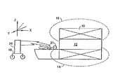
図1において、MRI 10は、動作中、そのコア部12の内部に高強度の電磁界を発生する。磁界はまた、磁力線14及び16で示されているように、コア外部まで広がる。車輪が装備されたトロリ18は、その上に患者21の生命徴候を監視できるよう電子機器20を搭載している。電子機器20には保護回路が設けられており、その詳細を図2に示す。トロリ18がMRIユニット10の近傍に移動される時、技師は電子機器20を磁石間近に接近させ且つ極めて高い磁界強度にそれをさらすことができる。
【0008】
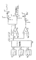
電子機器20の内部の保護回路は、図2に示されており、センサ22、24及び26の配置に関するデカルト座標系の各軸に合致した成分磁界強度を感知できるようにそれぞれ方位を合わせた3つのホールデバイス磁界センサ22、24及び26を包含している。ホールセンサ22は、X軸に沿う方向の磁界成分を表す信号出力を与えるよう方向を定める(図1参照)。ホールセンサ24は、Y軸に沿う方向の磁界成分を表す信号出力を与えるよう配置しさらにホールセンサ26は、Z軸に沿う方向の磁界成分を表す信号出力を与えるよう配置する。
【0009】
ホールセンサ22、24及び26は、そのぞれぞれの出力をベクトル変換器28へ送り、これが、次に、その値がセンサ出力の各々を2乗した値の和の平方根に等しい電圧出力を与える。ライン30上に生ずる電位は、ホールセンサ22、24及び26で感知されたX、Y及びZの磁界成分の各々のベクトル和の絶対値に等しい。ベクトル変換器28は、市販回路であり、Analog Devices社から販売されている3つのベクトル変換器モジュールAD637から成る。
【0010】
ベクトル変換器の出力は、比較器32及び34に印加する。一対の基準電圧A及びBも比較器32及び34に印加され、それらの出力にライン30上の電圧が各基準電圧を超える時に段階値を示すようにさせることができる。比較器34は、ヒステリシスを示し、それによって、その出力は、高くなりさえすれば、その出力を高い状態へ旋回させた入力値より少ない設定値であるレベルにその入力値が減らされるまで高い状態で維持される。
【0011】
基準電圧Aは、感知されるベクトル磁界強度値が警戒状態に達する時の電圧変換器30からの出力を表すレベルに設定する。故に、ライン30上の電位が基準電圧Aを越える時、比較器34の出力は高レベルに上昇しそれによってトランジスタ36が導通状態になる。結果として、黄色の表示灯が点灯して電子機器20の近辺の磁界強度が既に警戒状態に達したという警報を発する。
【0012】
基準電圧Bは、電圧レベルAより高いレベルに設定され、且つ感知されたベクトル磁界強度が機器損傷又は顕著な信号の品質低下を生じ得るレベルに達した時に生ずるベクトル変換器28からの信号出力を表す。該条件下で、比較器32は、トランジスタ42及び44を導通状態にする高出力を与える。トランジスタ42の導通によって、赤の停止表示灯46が点灯する。トランジスタ44の導通によって、コレクタライン45上でマイナスの電圧変動が生じ、これは電子機器20のオン/オフ制御入力(非表示)によって停止信号と認知される。それに応答して、電子機器は、正の電圧シフトがコレクタライン45上で再度感知されるまでその動作を停止する。
【0013】
その後でもしオペレータが、高磁界強度の領域から、ライン30の出力が基準電圧A以下に、少なくとも比較器32のヒステリシスレベルまで降下するよう、電子機器20を移動させると、比較器32の出力は低レベルまで落ちる。この作用でトランジスタ42及び44が非導通状態になり、これにより停止表示灯46がタンオフされそして電子機器20がタンオンされる。
【0014】
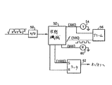
図3に戻り、図2で示した回路のディジタル型を図示する。ベクトル変換器28からの出力がアナログ/ディジタル(A/D)変換器50に印加され、これが次に状態機械52にその出力を供給する。一例として、状態機械52は、30ガウスのベクトル磁界量に等価であるA/D変換器50からの入力電位に応答して黄色の警報灯54を点灯してよい。同時に、可聴アラーム56が付勢され注意を払うよう知らせる。
【0015】
もし、A/D変換器50からの検出磁界強度の出力が50ガウスを越えると、ライン58経由で振動信号がアラーム56に印加され、これがアラーム56の音色を初期周波数に変調する働きをする。測定磁界強度が増加するにつれ、アラーム56の変調周波数も増加し、その装置が比較的高い磁界強度を経験しつつあることを指し示す。表示された磁界強度90ガウスでは、状態機械52は赤色灯60を点灯し、これによって停止が差し迫っていることを示す。最後に、A/D変換器50からの出力が100ガウス以上の磁界強度を示すと、マイナス方向の電圧振動を出力するラッチ62へ出力が送られ、これが上述のように電子機器20を使用不能にする。感知される磁界強度がプリセットレベル以下に下がる時だけ、ラッチ62がリセットされ、それによってプラス方向の電圧振動が与えられ電子機器20の動作を再設定する。
【0016】
上に示すように、ベクトル変換器28は、各平方の和の平方根を算出することによって3つのセンサ出力のベクトル和を計算して、感知磁界のベクトルの大きさに比例する電圧を音声アラームと状態機械52の両方に供給する。ベクトル計算は、比較器を各ホールセンサと共に用いた場合より正確な入射磁界強度の特性付けを考慮したものである。ベクトル値の計算に固有なものとして、ベクトル変換器28はセンサ電圧の平方を計算し且つ用いるので、従って同じ性能でバイポーラ磁界を感知することが可能である。ベクトル変換器28の出力は、線形かもしくは対数の何れであってもよい。後者の場合、基準電位は適宜に調整する。
【0017】
前出の記述は本発明の例証になるものに過ぎないと理解すべきである。種々の代替及び修正は、本発明から逸れることなく当業者によって案出されてよい。例えば、3つの磁界センサを示したが、それより少ないセンサでも所望の磁界強度信号を与えるには十分であることもある(例えば、X及びY)。さらに、受動磁束指示素子を用いて入射磁界を加算し且つその加算磁界を単一の磁界センサへ送ってよい。上文では好ましい磁界センサとしてホール効果デバイスを説明したが、他の磁力測定技術:例えば、磁気抵抗装置、飽和インダクタンス装置、磁束ゲート装置、及び磁性光学材料を用いる光ファイバセンサを使用することもできる。
【0018】
以上、本発明の実施例について詳述したが、以下、本発明の各実施態様の例を示す。
【0019】
[実施態様1]高レベルの電磁界(16)の存在下における搬送可能な電子システムの保護用回路であって、
前記電磁界(16)の成分磁界強度を表す出力信号を生成する磁界感知手段(22、24、26)と、
前記磁界感知手段に接続され、前記出力信号に応答して、前記電磁界(16)のベクトル強度を表す大きさを有する出力を与える回路手段(28)と、
第一しきい値(Ref A)に到達する前記回路手段(28)からの出力に応答して、前記電磁界(16)の前記ベクトル強度が警戒レベルに到達したという信号を明示する第一指示手段(34、36、38、52)と、
前記回路手段(28)からの出力が、前記第一しきい値より高い第二しきい値(RefB)に到達した時に表示を発する第二指示手段(32、42、44、52)と、
を備えて成る回路。
【0020】
[実施態様2]前記第二指示手段(32、42、44、52)からの前記表示によって前記電子システムが使用不能になることを特徴とする実施態様1記載の回路。
【0021】
[実施態様3]前記第二指示手段(32、42、44、52)がさらに、前記回路手段(28)からの前記出力が前記第二しきい値(Ref B)に到達した時に前記表示を発する比較器(32)を有し、該比較器(32)はさらに、前記回路手段(28)からの前記出力が前記第一しきい値(Ref A)より下に下がった時だけ前記表示を除去するよう作用することを特徴とする実施態様1記載の回路。
【0022】
[実施態様4]前記第一指示手段(52)がさらに、前記回路手段(28)からの前記出力が前記第一しきい値(Ref A)を越えた時に可聴アラーム(56)を始動させ、さらに前記可聴アラーム(56)を変調して、聞き手が前記第一しきい値(Ref A)と第二しきい値(RefB)との間で前記電磁界(16)の前記ベクトル強度の変化を識別できるようにした実施態様3記載の回路。
【0023】
[実施態様5]前記第一しきい値(Ref A)と第二しきい値(Ref B)との間にあって、前記第二しきい値(Ref B)により近い第三しきい値に達した時に、前記第二指示手段が警報灯(60)を点灯させることを特徴とする実施態様3記載の回路。
【0024】
[実施態様6]前記磁界感知手段(22、24、26)が、三次元デカルト座標系の軸に沿って存在する成分磁界強度を感知できるようにそれぞれ方位を合わせた、少なくとも3つのホール感知装置を備えている実施態様1記載の回路。
【0025】
[実施態様7]前記第一指示手段(34、36、38、52)と前記第二指示手段(32、42、44、52)とがディジタル型の状態機械(52)の一部分として形成されることを特徴とする実施態様1記載の回路。
【0026】
[実施態様8]高レベルの電磁界の存在下において搬送可能な電子システムを保護するための方法において、
前記電磁界の成分磁界強度を表す出力信号を生成するステップと、
前記出力信号を結合して、前記電磁界のベクトル強度を表す大きさを有するベクトル出力を与えるステップと、
前記ベクトル出力が第一しきい値に達した時に、前記電磁界の前記ベクトル強度が警戒レベルに到達したという信号を明示するステップと、
前記ベクトル出力が、前記第一しきい値より高い第二しきい値に到達した時に、そのことを示す表示を発するステップと、
を備えて成る方法。
【0027】
[実施態様9]前記表示に応答して前記電子システムを使用不能にするステップをさらに備えて成る実施態様8記載の方法。
【0028】
[実施態様10]前記ベクトル出力が前記第二しきい値に到達した時前記表示が発せられた後、前記ベクトル出力が前記第一しきい値より下に下がる時だけ前記表示を除去するステップをさらに備えて成る実施態様8記載の方法。
【0029】
【発明の効果】
以上説明したように、本発明を用いることにより、高レベルの電磁界の存在下における搬送可能な電子システムを、該電磁界から保護することができる。
【図面の簡単な説明】
【図1】MRIユニットと患者に取り付けられる移動可能な電子監視システムとを示す略図である。
【図2】本発明を具体化する保護回路を示す図である。
【図3】アラーム状態の複数表示を可能にする保護回路の一部の別の実施例を示す図である。
【符号の説明】
22、24、26:ホールセンサ
28:ベクトル変換器
32、34:比較器
38、46:表示灯[0001]
[Industrial application fields]
The present invention relates to a magnetic field sensor, and more particularly to a magnetic field sensor that is used with an electronic device and controls the operation of the electronic device in accordance with the strength of a sensing electromagnetic field.
[0002]
[Prior art]
Magnetic resonance imaging (MRI) systems include large magnetic coil structures that create intense magnetic fields in the immediate vicinity. Within the opening of the coil structure (where the patient is located), the magnetic field strength may be in the range of 2,000 Gauss to 15,000 Gauss. It is known that the magnetic field strength decreases rapidly with increasing distance from the coil structure, but there is still a strong residual magnetic field inside the MRI radio frequency (RF) enclosure. For this reason, great care has been taken to ensure that no magnetic article is placed in the MRI RF enclosure or near the MRI coil structure.
[0003]
Today, some diagnostic procedures for a patient are performed while the patient is in the MRI unit. During these procedures, signs related to the patient's life need to be monitored. In previous systems, the monitoring equipment had to be placed in an area that was previously known to be at a safe magnetic field level, which limited the flexibility of use of the equipment. .
[0004]
Certain types of surveillance electronics are desired to be kept inside the MRI RF enclosure, but the risk that an engineer may bring them into a high field strength region during the process of moving the electronics Is always present. Such a magnetic field can cause damage to the equipment, or an emergency can be reported incorrectly, or more seriously, the emergency signal may be obscured as false normal. There is a risk of distorting the patient's signal during the procedure by falsifying the patient's vital signs or altering the patient's signal. Therefore, there is a need for electronic equipment to be installed inside the RF enclosure of the MRI unit and to operate to reliably generate accurate vital signs signals for the patient. In addition, there is a need to protect electronic engineers when they bring electronic devices close to the MRI unit.
[0005]
OBJECT OF THE INVENTION
It is an object of the present invention to provide an apparatus for protecting a transportable electronic system in the presence of a high level electromagnetic field from the electromagnetic field.
[0006]
SUMMARY OF THE INVENTION
When a high level electromagnetic field is present, the electronic device is controlled by a protection circuit. The protection circuit includes a magnetic field sensor device that provides an output signal representative of the magnetic field strength components along three orthogonal spatial axes. A vector converter circuit is connected to the magnetic field sensor and provides an output having a magnitude representing the vector sum of the electromagnetic field strength components. The first indicator indicates a warning signal that the magnetic field strength has already reached the alert level in response to the vector converter output reaching the first threshold. The second indicator disables the electronics in response to the vector converter output reaching a second threshold value that is higher than the first threshold value. Yet another circuit is provided to make it reusable when moving the electronics out of the region where the magnetic field exceeds the first threshold.
[0007]
【Example】
In FIG. 1, the
[0008]
The protection circuit inside the
[0009]
[0010]
The output of the vector converter is applied to the
[0011]
The reference voltage A is set to a level that represents the output from the
[0012]
The reference voltage B is set to a level higher than the voltage level A, and the signal output from the
[0013]
After that, if the operator moves the
[0014]
Returning to FIG. 3, the digital version of the circuit shown in FIG. 2 is illustrated. The output from
[0015]
If the detected magnetic field intensity output from the A / D converter 50 exceeds 50 Gauss, a vibration signal is applied to the
[0016]
As shown above, the
[0017]
It should be understood that the foregoing description is only illustrative of the invention. Various alternatives and modifications may be devised by those skilled in the art without departing from the invention. For example, although three magnetic field sensors have been shown, fewer sensors may be sufficient to provide the desired magnetic field strength signal (eg, X and Y). Further, the incident magnetic field may be added using a passive magnetic flux indicating element and the added magnetic field may be sent to a single magnetic field sensor. Although the Hall effect device has been described above as a preferred magnetic field sensor, other magnetic force measurement techniques can be used, for example, magnetoresistive devices, saturation inductance devices, magnetic flux gating devices, and fiber optic sensors using magnetic optical materials. .
[0018]
As mentioned above, although the Example of this invention was explained in full detail, the example of each embodiment of this invention is shown below.
[0019]
[Embodiment 1] A circuit for protecting a transportable electronic system in the presence of a high level electromagnetic field (16) comprising:
Magnetic field sensing means (22, 24, 26) for generating an output signal representing the component magnetic field strength of the electromagnetic field (16);
Circuit means (28) connected to the magnetic field sensing means for providing an output having a magnitude representative of the vector strength of the electromagnetic field (16) in response to the output signal;
In response to the output from the circuit means (28) reaching the first threshold (Ref A), a first indication that clearly indicates a signal that the vector intensity of the electromagnetic field (16) has reached a warning level Means (34, 36, 38, 52);
Second indicating means (32, 42, 44, 52) for giving an indication when the output from the circuit means (28) reaches a second threshold value (RefB) higher than the first threshold value;
A circuit comprising:
[0020]
[Embodiment 2] The circuit according to embodiment 1, wherein the electronic system is disabled by the display from the second instruction means (32, 42, 44, 52).
[0021]
[Embodiment 3] The second instruction means (32, 42, 44, 52) further displays the indication when the output from the circuit means (28) reaches the second threshold value (Ref B). A comparator (32) that emits, and the comparator (32) further displays the display only when the output from the circuit means (28) falls below the first threshold (Ref A). The circuit of embodiment 1, wherein the circuit acts to eliminate.
[0022]
[Embodiment 4] The first instruction means (52) further triggers an audible alarm (56) when the output from the circuit means (28) exceeds the first threshold (Ref A), Furthermore, the audible alarm (56) is modulated so that the listener can change the vector intensity of the electromagnetic field (16) between the first threshold (Ref A) and the second threshold (RefB). The circuit according to the third embodiment, which can be identified.
[0023]
[Embodiment 5] The third threshold value reached between the first threshold value (Ref A) and the second threshold value (Ref B) and closer to the second threshold value (Ref B) 4. The circuit according to embodiment 3, characterized in that the second indicator means turns on an alarm lamp (60).
[0024]
[Embodiment 6] At least three Hall sensing devices in which the magnetic field sensing means (22, 24, 26) are respectively oriented so as to sense the component magnetic field intensity existing along the axis of the three-dimensional Cartesian coordinate system. The circuit of embodiment 1, comprising:
[0025]
[Embodiment 7] The first indicating means (34, 36, 38, 52) and the second indicating means (32, 42, 44, 52) are formed as a part of a digital type state machine (52). The circuit according to embodiment 1, characterized by the above.
[0026]
[Embodiment 8] In a method for protecting an electronic system transportable in the presence of a high level electromagnetic field,
Generating an output signal representing the component magnetic field strength of the electromagnetic field;
Combining the output signals to provide a vector output having a magnitude representative of the vector strength of the electromagnetic field;
Demonstrating a signal that the vector strength of the electromagnetic field has reached a warning level when the vector output reaches a first threshold;
When the vector output reaches a second threshold value that is higher than the first threshold value, issuing an indication to that effect;
Comprising a method.
[0027]
[Embodiment 9] The method of
[0028]
[Embodiment 10] A step of removing the display only when the vector output falls below the first threshold after the display is issued when the vector output reaches the second threshold. Embodiment 9. The method of
[0029]
【The invention's effect】
As described above, by using the present invention, a transportable electronic system in the presence of a high level electromagnetic field can be protected from the electromagnetic field.
[Brief description of the drawings]
FIG. 1 is a schematic diagram showing an MRI unit and a movable electronic monitoring system attached to a patient.
FIG. 2 is a diagram showing a protection circuit embodying the present invention.
FIG. 3 is a diagram illustrating another embodiment of a portion of a protection circuit that allows multiple indications of alarm conditions.
[Explanation of symbols]
22, 24, 26: Hall sensor 28:
Claims (10)
前記電磁界の成分磁界強度を表す出力信号を生成する磁界感知手段と、
前記磁界感知手段に接続され、前記出力信号に応答して、前記電磁界のベクトル強度を表す大きさを有する出力を与える回路手段と、
第一しきい値に到達する前記回路手段からの出力に応答して、前記電磁界の前記ベクトル強度が警戒レベルに到達したという信号を明示する第一指示手段と、
前記回路手段からの出力が、前記第一しきい値より高い第二しきい値に到達した時に表示を発する第二指示手段と、
を備えて成る回路。A circuit for protecting a transportable electronic system in the presence of a high level electromagnetic field,
Magnetic field sensing means for generating an output signal representing the component magnetic field strength of the electromagnetic field;
Circuit means connected to the magnetic field sensing means for providing an output having a magnitude representative of a vector strength of the electromagnetic field in response to the output signal;
In response to an output from the circuit means reaching a first threshold, first indicating means for clearly indicating a signal that the vector strength of the electromagnetic field has reached a warning level;
Second indicating means for emitting a display when an output from the circuit means reaches a second threshold value higher than the first threshold value;
A circuit comprising:
前記電磁界の成分磁界強度を表す出力信号を生成するステップと、 Generating an output signal representing a component magnetic field strength of the electromagnetic field;
前記出力信号を結合して、前記電磁界のベクトル強度を表す大きさを有するベクトル出力を与えるステップと、 Combining the output signals to provide a vector output having a magnitude representative of the vector strength of the electromagnetic field;
前記ベクトル出力が第一しきい値に達した時に、前記電磁界の前記ベクトル強度が警戒レベルに到達したという信号を明示するステップと、 Demonstrating a signal that the vector strength of the electromagnetic field has reached a warning level when the vector output reaches a first threshold;
前記ベクトル出力が、前記第一しきい値より高い第二しきい値に到達した時に、そのことを示す表示を発するステップと、 When the vector output reaches a second threshold value that is higher than the first threshold value;
を備えて成る方法。 Comprising a method.
Applications Claiming Priority (2)
| Application Number | Priority Date | Filing Date | Title |
|---|---|---|---|
| US501,264 | 1995-07-11 | ||
| US08/501,264 US5629622A (en) | 1995-07-11 | 1995-07-11 | Magnetic field sense system for the protection of connected electronic devices |
Publications (2)
| Publication Number | Publication Date |
|---|---|
| JPH0928691A JPH0928691A (en) | 1997-02-04 |
| JP3628811B2 true JP3628811B2 (en) | 2005-03-16 |
Family
ID=23992814
Family Applications (1)
| Application Number | Title | Priority Date | Filing Date |
|---|---|---|---|
| JP17468596A Expired - Fee Related JP3628811B2 (en) | 1995-07-11 | 1996-07-04 | Magnetic field sensing system |
Country Status (4)
| Country | Link |
|---|---|
| US (1) | US5629622A (en) |
| JP (1) | JP3628811B2 (en) |
| DE (1) | DE19626596C2 (en) |
| GB (1) | GB2303261B (en) |
Cited By (1)
| Publication number | Priority date | Publication date | Assignee | Title |
|---|---|---|---|---|
| KR20180041713A (en) * | 2015-08-19 | 2018-04-24 | 알레그로 마이크로시스템스, 엘엘씨 | A magnetic field sensor for detecting the magnitude of the magnetic field by arbitrary detection |
Families Citing this family (102)
| Publication number | Priority date | Publication date | Assignee | Title |
|---|---|---|---|---|
| FR2756636B1 (en) * | 1996-11-29 | 1999-01-08 | Odam Office De Distribution D | DEVICE FOR MEASURING AND MONITORING THE INTENSITY OF A LOCAL MAGNETIC FIELD AND APPARATUS COMPRISING SUCH A DEVICE |
| DE69822099T2 (en) * | 1997-07-08 | 2005-01-20 | Koninklijke Philips Electronics N.V. | INPUT DEVICE FOR A GRAPHICAL DISPLAY WITH MAGNETIC SENSORS |
| US8244370B2 (en) * | 2001-04-13 | 2012-08-14 | Greatbatch Ltd. | Band stop filter employing a capacitor and an inductor tank circuit to enhance MRI compatibility of active medical devices |
| US9061139B2 (en) * | 1998-11-04 | 2015-06-23 | Greatbatch Ltd. | Implantable lead with a band stop filter having a capacitor in parallel with an inductor embedded in a dielectric body |
| US6701176B1 (en) * | 1998-11-04 | 2004-03-02 | Johns Hopkins University School Of Medicine | Magnetic-resonance-guided imaging, electrophysiology, and ablation |
| DE10107188A1 (en) * | 2001-02-15 | 2002-09-19 | Mipm Mammendorfer Inst Fuer Ph | Device for long-term monitoring of strong magnetic fields |
| US7787958B2 (en) * | 2001-04-13 | 2010-08-31 | Greatbatch Ltd. | RFID detection and identification system for implantable medical lead systems |
| US7899551B2 (en) * | 2001-04-13 | 2011-03-01 | Greatbatch Ltd. | Medical lead system utilizing electromagnetic bandstop filters |
| US8219208B2 (en) | 2001-04-13 | 2012-07-10 | Greatbatch Ltd. | Frequency selective passive component networks for active implantable medical devices utilizing an energy dissipating surface |
| WO2002083016A1 (en) | 2001-04-13 | 2002-10-24 | Surgi-Vision, Inc. | Systems and methods for magnetic-resonance-guided interventional procedures |
| US8989870B2 (en) * | 2001-04-13 | 2015-03-24 | Greatbatch Ltd. | Tuned energy balanced system for minimizing heating and/or to provide EMI protection of implanted leads in a high power electromagnetic field environment |
| US9295828B2 (en) | 2001-04-13 | 2016-03-29 | Greatbatch Ltd. | Self-resonant inductor wound portion of an implantable lead for enhanced MRI compatibility of active implantable medical devices |
| US8712544B2 (en) | 2001-04-13 | 2014-04-29 | Greatbatch Ltd. | Electromagnetic shield for a passive electronic component in an active medical device implantable lead |
| US8457760B2 (en) | 2001-04-13 | 2013-06-04 | Greatbatch Ltd. | Switched diverter circuits for minimizing heating of an implanted lead and/or providing EMI protection in a high power electromagnetic field environment |
| US8977355B2 (en) * | 2001-04-13 | 2015-03-10 | Greatbatch Ltd. | EMI filter employing a capacitor and an inductor tank circuit having optimum component values |
| US20070088416A1 (en) * | 2001-04-13 | 2007-04-19 | Surgi-Vision, Inc. | Mri compatible medical leads |
| US7853325B2 (en) * | 2001-04-13 | 2010-12-14 | Greatbatch Ltd. | Cylindrical bandstop filters for medical lead systems |
| US8509913B2 (en) * | 2001-04-13 | 2013-08-13 | Greatbatch Ltd. | Switched diverter circuits for minimizing heating of an implanted lead and/or providing EMI protection in a high power electromagnetic field environment |
| US6693536B2 (en) * | 2001-10-31 | 2004-02-17 | Lockheed Martin Corporation | Electromagnetic radiation monitor |
| US6944489B2 (en) * | 2001-10-31 | 2005-09-13 | Medtronic, Inc. | Method and apparatus for shunting induced currents in an electrical lead |
| US6871091B2 (en) | 2001-10-31 | 2005-03-22 | Medtronic, Inc. | Apparatus and method for shunting induced currents in an electrical lead |
| US20030144720A1 (en) * | 2002-01-29 | 2003-07-31 | Villaseca Eduardo H. | Electromagnetic trap for a lead |
| US20030144718A1 (en) * | 2002-01-29 | 2003-07-31 | Zeijlemaker Volkert A. | Method and apparatus for shielding coating for MRI resistant electrode systems |
| US6937906B2 (en) | 2002-01-29 | 2005-08-30 | Medtronic, Inc. | Method and apparatus for detecting static magnetic fields |
| US6985775B2 (en) * | 2002-01-29 | 2006-01-10 | Medtronic, Inc. | Method and apparatus for shunting induced currents in an electrical lead |
| US7082328B2 (en) | 2002-01-29 | 2006-07-25 | Medtronic, Inc. | Methods and apparatus for controlling a pacing system in the presence of EMI |
| US20040017192A1 (en) * | 2002-04-15 | 2004-01-29 | Clymer Technologies, Llc | 3-axis magnetic angular orientation sensor |
| US6904307B2 (en) | 2002-05-29 | 2005-06-07 | Surgi-Vision, Inc. | Magnetic resonance probes |
| US20040243193A1 (en) * | 2003-05-30 | 2004-12-02 | Ballis Joseph J. | Electromagnetic interference alarm |
| US7231251B2 (en) * | 2003-08-14 | 2007-06-12 | Cardiac Pacemakers, Inc. | EMI detection for implantable medical devices |
| WO2005017548A1 (en) * | 2003-08-15 | 2005-02-24 | Koninklijke Philips Electronics N.V. | Mri system with wireless identification capability |
| US20050070972A1 (en) * | 2003-09-26 | 2005-03-31 | Wahlstrand Carl D. | Energy shunt for producing an MRI-safe implantable medical device |
| US7660620B2 (en) * | 2003-09-29 | 2010-02-09 | Medtronic, Inc. | Timing techniques for magnetic resonance imaging |
| US8332011B2 (en) * | 2003-09-29 | 2012-12-11 | Medtronic, Inc. | Controlling blanking during magnetic resonance imaging |
| US7019522B1 (en) * | 2004-01-23 | 2006-03-28 | Advanced Design Consulting Usa | Apparatus for measuring the magnetic field produced by an insertion device |
| US7844344B2 (en) | 2004-03-30 | 2010-11-30 | Medtronic, Inc. | MRI-safe implantable lead |
| US7877150B2 (en) * | 2004-03-30 | 2011-01-25 | Medtronic, Inc. | Lead electrode for use in an MRI-safe implantable medical device |
| US9155877B2 (en) * | 2004-03-30 | 2015-10-13 | Medtronic, Inc. | Lead electrode for use in an MRI-safe implantable medical device |
| US8989840B2 (en) * | 2004-03-30 | 2015-03-24 | Medtronic, Inc. | Lead electrode for use in an MRI-safe implantable medical device |
| US7174219B2 (en) * | 2004-03-30 | 2007-02-06 | Medtronic, Inc. | Lead electrode for use in an MRI-safe implantable medical device |
| US7844343B2 (en) * | 2004-03-30 | 2010-11-30 | Medtronic, Inc. | MRI-safe implantable medical device |
| DE102004017185B4 (en) * | 2004-04-07 | 2010-06-10 | Siemens Ag | Overall medical system |
| DE102004029941B3 (en) * | 2004-06-21 | 2005-12-15 | Infineon Technologies Ag | System for evaluating a sensor signal |
| WO2006034551A1 (en) * | 2004-09-28 | 2006-04-06 | The University Of Queensland | Magnetic field dosimeter |
| US7369898B1 (en) * | 2004-12-22 | 2008-05-06 | Pacesetter, Inc. | System and method for responding to pulsed gradient magnetic fields using an implantable medical device |
| US20060173295A1 (en) * | 2005-01-26 | 2006-08-03 | Zeijlemaker Volkert A | Apparatus for detecting strong magnetic fields for protection of medical devices |
| US8280526B2 (en) * | 2005-02-01 | 2012-10-02 | Medtronic, Inc. | Extensible implantable medical lead |
| US8825180B2 (en) * | 2005-03-31 | 2014-09-02 | Medtronic, Inc. | Medical electrical lead with co-radial multi-conductor coil |
| US8027736B2 (en) * | 2005-04-29 | 2011-09-27 | Medtronic, Inc. | Lead electrode for use in an MRI-safe implantable medical device |
| US7853332B2 (en) * | 2005-04-29 | 2010-12-14 | Medtronic, Inc. | Lead electrode for use in an MRI-safe implantable medical device |
| US8224462B2 (en) | 2005-11-11 | 2012-07-17 | Greatbatch Ltd. | Medical lead system utilizing electromagnetic bandstop filters |
| EP1945297B1 (en) * | 2005-11-11 | 2016-08-10 | Greatbatch Ltd. | Tank filters placed in series with the lead wires or circuits of active medical devices to enhance mri compatibility |
| US7853324B2 (en) * | 2005-11-11 | 2010-12-14 | Greatbatch Ltd. | Tank filters utilizing very low K materials, in series with lead wires or circuits of active medical devices to enhance MRI compatibility |
| US7693568B2 (en) * | 2006-03-30 | 2010-04-06 | Medtronic, Inc. | Medical device sensing and detection during MRI |
| US8903505B2 (en) | 2006-06-08 | 2014-12-02 | Greatbatch Ltd. | Implantable lead bandstop filter employing an inductive coil with parasitic capacitance to enhance MRI compatibility of active medical devices |
| US9042999B2 (en) * | 2006-06-08 | 2015-05-26 | Greatbatch Ltd. | Low loss band pass filter for RF distance telemetry pin antennas of active implantable medical devices |
| US8116862B2 (en) * | 2006-06-08 | 2012-02-14 | Greatbatch Ltd. | Tank filters placed in series with the lead wires or circuits of active medical devices to enhance MRI compatibility |
| US9468750B2 (en) | 2006-11-09 | 2016-10-18 | Greatbatch Ltd. | Multilayer planar spiral inductor filter for medical therapeutic or diagnostic applications |
| US9031670B2 (en) | 2006-11-09 | 2015-05-12 | Greatbatch Ltd. | Electromagnetic shield for a passive electronic component in an active medical device implantable lead |
| US10537730B2 (en) * | 2007-02-14 | 2020-01-21 | Medtronic, Inc. | Continuous conductive materials for electromagnetic shielding |
| US9044593B2 (en) * | 2007-02-14 | 2015-06-02 | Medtronic, Inc. | Discontinuous conductive filler polymer-matrix composites for electromagnetic shielding |
| DE102007013770A1 (en) | 2007-03-22 | 2008-10-02 | Siemens Ag | Mobile radio transmission unit |
| US8483842B2 (en) * | 2007-04-25 | 2013-07-09 | Medtronic, Inc. | Lead or lead extension having a conductive body and conductive body contact |
| US9037263B2 (en) | 2008-03-12 | 2015-05-19 | Medtronic, Inc. | System and method for implantable medical device lead shielding |
| US10080889B2 (en) | 2009-03-19 | 2018-09-25 | Greatbatch Ltd. | Low inductance and low resistance hermetically sealed filtered feedthrough for an AIMD |
| US9108066B2 (en) | 2008-03-20 | 2015-08-18 | Greatbatch Ltd. | Low impedance oxide resistant grounded capacitor for an AIMD |
| US8416076B2 (en) * | 2008-04-02 | 2013-04-09 | The Trustees Of Dartmouth College | Magnetic proximity sensor system and associated methods of sensing a magnetic field |
| IT1391077B1 (en) * | 2008-09-26 | 2011-11-18 | Elab Scient S R L | "MAGNETIC FIELD PRESENCE DETECTOR, IN SPECIES FOR HOUSEHOLD USE" |
| EP2349453A4 (en) | 2008-10-30 | 2015-07-01 | Greatbatch Ltd | Capacitor and inductor elements physically disposed in series whose lumped parameters are electrically connected in parallel to form a bandstop filter |
| US8447414B2 (en) * | 2008-12-17 | 2013-05-21 | Greatbatch Ltd. | Switched safety protection circuit for an AIMD system during exposure to high power electromagnetic fields |
| WO2010126877A1 (en) | 2009-04-30 | 2010-11-04 | Medtronic, Inc. | Shielding an implantable medical lead |
| US8456160B2 (en) * | 2009-08-04 | 2013-06-04 | Sypris Test & Measurement | Three axis field monitor |
| US9919158B2 (en) | 2009-12-29 | 2018-03-20 | Medtronic, Inc. | Configuring operating parameters of a medical device based on exposure to a disruptive energy field |
| DE102010011120A1 (en) * | 2010-03-11 | 2011-09-15 | Max-Delbrück-Centrum für Molekulare Medizin | Signaling device for use as warning device for detecting magnetic field of field magnet in magnetic resonance system, has signal transmitter for emitting warning signal when magnetic field is detected by magnetic field sensor device |
| US10391320B2 (en) | 2011-01-28 | 2019-08-27 | Medtronic, Inc. | Techniques for detecting magnetic resonance imaging field |
| US9795792B2 (en) | 2011-02-25 | 2017-10-24 | Medtronic, Inc. | Emergency mode switching for non-pacing modes |
| US9427596B2 (en) | 2013-01-16 | 2016-08-30 | Greatbatch Ltd. | Low impedance oxide resistant grounded capacitor for an AIMD |
| US9931514B2 (en) | 2013-06-30 | 2018-04-03 | Greatbatch Ltd. | Low impedance oxide resistant grounded capacitor for an AIMD |
| US10350421B2 (en) | 2013-06-30 | 2019-07-16 | Greatbatch Ltd. | Metallurgically bonded gold pocket pad for grounding an EMI filter to a hermetic terminal for an active implantable medical device |
| US10596369B2 (en) | 2011-03-01 | 2020-03-24 | Greatbatch Ltd. | Low equivalent series resistance RF filter for an active implantable medical device |
| US11198014B2 (en) | 2011-03-01 | 2021-12-14 | Greatbatch Ltd. | Hermetically sealed filtered feedthrough assembly having a capacitor with an oxide resistant electrical connection to an active implantable medical device housing |
| US10272252B2 (en) | 2016-11-08 | 2019-04-30 | Greatbatch Ltd. | Hermetic terminal for an AIMD having a composite brazed conductive lead |
| CN103890600A (en) * | 2011-10-24 | 2014-06-25 | 皇家飞利浦有限公司 | Automatic recovery protection of electromechanical components in strong magnetic fields |
| WO2013158189A1 (en) | 2012-04-19 | 2013-10-24 | Medtronic, Inc. | Paired medical lead bodies with braided conductive shields having different physical parameter values |
| US9981124B2 (en) | 2012-04-26 | 2018-05-29 | Medtronic, Inc. | Devices and techniques for detecting magnetic resonance imaging field |
| USRE46699E1 (en) | 2013-01-16 | 2018-02-06 | Greatbatch Ltd. | Low impedance oxide resistant grounded capacitor for an AIMD |
| US9733106B2 (en) | 2013-05-24 | 2017-08-15 | Allegro Microsystems, Llc | Magnetic field sensor to detect a magnitude of a magnetic field in any direction |
| WO2014189733A1 (en) * | 2013-05-24 | 2014-11-27 | Allegro Microsystems, Llc | Magnetic field sensor for detecting a magnetic field in any direction above thresholds |
| US9993638B2 (en) | 2013-12-14 | 2018-06-12 | Medtronic, Inc. | Devices, systems and methods to reduce coupling of a shield and a conductor within an implantable medical lead |
| JP2015228936A (en) * | 2014-06-04 | 2015-12-21 | 佐保 ミドリ | Magnetic characteristics warning device |
| WO2016014427A1 (en) | 2014-07-23 | 2016-01-28 | Medtronic, Inc. | Methods of shielding implantable medical leads and implantable medical lead extensions |
| WO2016014816A1 (en) | 2014-07-24 | 2016-01-28 | Medtronic, Inc. | Methods of shielding implantable medical leads and implantable medical lead extensions |
| WO2016091745A1 (en) * | 2014-12-08 | 2016-06-16 | Koninklijke Philips N.V. | Radio frequency receive coil for use in magnetic resonance imaging systems with disconnection warning |
| WO2017018974A1 (en) * | 2015-07-24 | 2017-02-02 | Zevex, Inc. | Magnetic pressure sensing system for an infusion pump |
| US10249415B2 (en) | 2017-01-06 | 2019-04-02 | Greatbatch Ltd. | Process for manufacturing a leadless feedthrough for an active implantable medical device |
| EP3531151B1 (en) * | 2018-02-27 | 2020-04-22 | Melexis Technologies SA | Redundant sensor error reduction |
| US10912945B2 (en) | 2018-03-22 | 2021-02-09 | Greatbatch Ltd. | Hermetic terminal for an active implantable medical device having a feedthrough capacitor partially overhanging a ferrule for high effective capacitance area |
| US10905888B2 (en) | 2018-03-22 | 2021-02-02 | Greatbatch Ltd. | Electrical connection for an AIMD EMI filter utilizing an anisotropic conductive layer |
| US11819285B2 (en) | 2019-04-05 | 2023-11-21 | Covidien Lp | Magnetic interference detection systems and methods |
| CN113156348A (en) * | 2021-03-16 | 2021-07-23 | 天津国电津能热电有限公司 | Electromagnetic monitoring device and method for power equipment state |
| CN113274517B (en) * | 2021-05-19 | 2023-04-28 | 深圳瑞格泰科医疗科技有限公司 | Non-magnetic ultraviolet disinfection system with self-adaptive magnetic field intensity |
| DE102024208750A1 (en) * | 2024-09-13 | 2026-03-19 | Siemens Healthineers Ag | Measuring device for measuring magnetic field strength in the vicinity of a magnetic resonance device |
Family Cites Families (5)
| Publication number | Priority date | Publication date | Assignee | Title |
|---|---|---|---|---|
| US3418572A (en) * | 1966-02-11 | 1968-12-24 | Thomas G. Humphreys Jr. | Apparatus including variable frequency indicating means for locating and tracing conductive structures |
| CA1308167C (en) * | 1988-10-25 | 1992-09-29 | Fernando C. Lebron | Magnetic field detector |
| US5256960A (en) * | 1991-04-09 | 1993-10-26 | Novini Amir R | Portable dual band electromagnetic field radiation measurement apparatus |
| US5309097A (en) * | 1992-04-15 | 1994-05-03 | Enrique Rodriguez | Video display terminal magnetic field detector |
| US5512823A (en) * | 1993-12-15 | 1996-04-30 | Eakes Research, Inc. | Electromagnetic field detector for detecting electromagnetic field strength in an extremely low frequency band and a very low frequency band |
-
1995
- 1995-07-11 US US08/501,264 patent/US5629622A/en not_active Expired - Lifetime
-
1996
- 1996-07-02 DE DE19626596A patent/DE19626596C2/en not_active Expired - Fee Related
- 1996-07-04 JP JP17468596A patent/JP3628811B2/en not_active Expired - Fee Related
- 1996-07-11 GB GB9614583A patent/GB2303261B/en not_active Expired - Fee Related
Cited By (2)
| Publication number | Priority date | Publication date | Assignee | Title |
|---|---|---|---|---|
| KR20180041713A (en) * | 2015-08-19 | 2018-04-24 | 알레그로 마이크로시스템스, 엘엘씨 | A magnetic field sensor for detecting the magnitude of the magnetic field by arbitrary detection |
| KR102629037B1 (en) * | 2015-08-19 | 2024-01-25 | 알레그로 마이크로시스템스, 엘엘씨 | Magnetic field sensor that detects the size of the magnetic field with random detection |
Also Published As
| Publication number | Publication date |
|---|---|
| JPH0928691A (en) | 1997-02-04 |
| DE19626596C2 (en) | 2001-03-15 |
| DE19626596A1 (en) | 1997-01-16 |
| GB9614583D0 (en) | 1996-09-04 |
| GB2303261A (en) | 1997-02-12 |
| US5629622A (en) | 1997-05-13 |
| GB2303261B (en) | 1999-06-16 |
Similar Documents
| Publication | Publication Date | Title |
|---|---|---|
| JP3628811B2 (en) | Magnetic field sensing system | |
| Hurwitz et al. | Acoustic analysis of gradient-coil noise in MR imaging. | |
| US8901928B2 (en) | MRI safety system | |
| US6396284B1 (en) | Ground resistance monitor | |
| EP3472090B1 (en) | Safety system | |
| CA1308167C (en) | Magnetic field detector | |
| CA1265582A (en) | Current sensing alarm arrangement for monitoring the presence of high voltage | |
| US6614211B1 (en) | Non-contact detector for sensing a periodically varying magnetic field | |
| CA2721794C (en) | Mri safety system | |
| JP3319310B2 (en) | Fault diagnosis circuit | |
| KR20010093015A (en) | Earth leakage detector | |
| EP1014101A2 (en) | Magnetic testing apparatus | |
| JP2544613Y2 (en) | SAR monitoring device in MR device | |
| DE50113188D1 (en) | Method and device for functional testing of a display device of a medical-technical device | |
| WO2024050931A1 (en) | Anti-collision device and method for scissor forklift | |
| JPH0368881A (en) | portable magnetic alarm device | |
| JP3335710B2 (en) | Magnetic resonance imaging equipment | |
| KR920001019Y1 (en) | Digital Measurement Central Control Display | |
| CN113126001A (en) | Electromagnetic monitoring system and method | |
| KR200192119Y1 (en) | Leakade current detection device for hospital | |
| JPH0698879A (en) | Nuclear magnetic resonance imaging apparatus | |
| RU2797174C2 (en) | Impact alarm system for parked vehicle | |
| JP2954905B2 (en) | Cylinder piston position detecting device and centralized control device therefor | |
| RU13728U1 (en) | DEVICE FOR CONTROL OF INSULATION AND PROTECTION OF MOBILE ELECTRIC INSTALLATIONS | |
| SU883874A1 (en) | Electric magnet operation checking device |
Legal Events
| Date | Code | Title | Description |
|---|---|---|---|
| A977 | Report on retrieval |
Free format text: JAPANESE INTERMEDIATE CODE: A971007 Effective date: 20041109 |
|
| TRDD | Decision of grant or rejection written | ||
| A01 | Written decision to grant a patent or to grant a registration (utility model) |
Free format text: JAPANESE INTERMEDIATE CODE: A01 Effective date: 20041111 |
|
| A61 | First payment of annual fees (during grant procedure) |
Free format text: JAPANESE INTERMEDIATE CODE: A61 Effective date: 20041209 |
|
| R150 | Certificate of patent or registration of utility model |
Free format text: JAPANESE INTERMEDIATE CODE: R150 |
|
| FPAY | Renewal fee payment (event date is renewal date of database) |
Free format text: PAYMENT UNTIL: 20081217 Year of fee payment: 4 |
|
| FPAY | Renewal fee payment (event date is renewal date of database) |
Free format text: PAYMENT UNTIL: 20081217 Year of fee payment: 4 |
|
| FPAY | Renewal fee payment (event date is renewal date of database) |
Free format text: PAYMENT UNTIL: 20091217 Year of fee payment: 5 |
|
| LAPS | Cancellation because of no payment of annual fees |