JP3625845B2 - Measuring instrument used mainly with vehicles - Google Patents
Measuring instrument used mainly with vehicles Download PDFInfo
- Publication number
- JP3625845B2 JP3625845B2 JP51398198A JP51398198A JP3625845B2 JP 3625845 B2 JP3625845 B2 JP 3625845B2 JP 51398198 A JP51398198 A JP 51398198A JP 51398198 A JP51398198 A JP 51398198A JP 3625845 B2 JP3625845 B2 JP 3625845B2
- Authority
- JP
- Japan
- Prior art keywords
- probe
- vehicle
- emitter
- emitters
- signal
- Prior art date
- Legal status (The legal status is an assumption and is not a legal conclusion. Google has not performed a legal analysis and makes no representation as to the accuracy of the status listed.)
- Expired - Lifetime
Links
Images


Classifications
-
- G—PHYSICS
- G01—MEASURING; TESTING
- G01B—MEASURING LENGTH, THICKNESS OR SIMILAR LINEAR DIMENSIONS; MEASURING ANGLES; MEASURING AREAS; MEASURING IRREGULARITIES OF SURFACES OR CONTOURS
- G01B11/00—Measuring arrangements characterised by the use of optical techniques
- G01B11/24—Measuring arrangements characterised by the use of optical techniques for measuring contours or curvatures
-
- G—PHYSICS
- G01—MEASURING; TESTING
- G01B—MEASURING LENGTH, THICKNESS OR SIMILAR LINEAR DIMENSIONS; MEASURING ANGLES; MEASURING AREAS; MEASURING IRREGULARITIES OF SURFACES OR CONTOURS
- G01B5/00—Measuring arrangements characterised by the use of mechanical techniques
- G01B5/0025—Measuring of vehicle parts
-
- G—PHYSICS
- G01—MEASURING; TESTING
- G01B—MEASURING LENGTH, THICKNESS OR SIMILAR LINEAR DIMENSIONS; MEASURING ANGLES; MEASURING AREAS; MEASURING IRREGULARITIES OF SURFACES OR CONTOURS
- G01B11/00—Measuring arrangements characterised by the use of optical techniques
- G01B11/24—Measuring arrangements characterised by the use of optical techniques for measuring contours or curvatures
- G01B11/245—Measuring arrangements characterised by the use of optical techniques for measuring contours or curvatures using a plurality of fixed, simultaneously operating transducers
Landscapes
- Physics & Mathematics (AREA)
- General Physics & Mathematics (AREA)
- Length Measuring Devices With Unspecified Measuring Means (AREA)
- Length Measuring Devices By Optical Means (AREA)
Description
発明の背景
本発明は、1996年9月16日付けの米国仮出願第60/026,195号からの優先権を主張する。本発明は、車両用測定システムに関する。
事故の後で車両のフレームをどの程度矯正したらよいのかを決定したり、または車両の車輪または他の部分を、どの程度整合すべきかを決定するために、現在まで多くの測定器が車両上で使用されてきた。機械的な測定器は使用方法が難しかった。機械的測定器の場合には、ユーザはかなりの知識を持っていなければならないし、使用するのに時間が掛かり、必要な精度が得られない。他の装置は、車両上の点の位置を測定するのに、音波を使用し、音波が発射された時間から、その音波が複数のセンサに達するまでの時間の経過を測定する。システムは、センサの測定値に悪影響を与える、工場内の空気ホース、および他の装置の外来ノイズに関する多くの問題を抱えている。また、これらのシステムは、精度の問題も抱えている。何故なら、音波が伝播する速度は、天候によっても異なるし、工場内を移動する空気の速度によっても異なるからである。他の装置は、車両上に登載してあるターゲットを使用し、ターゲットの位置を測定するために、レーザまたは他の光線により車両を走査する。これらのシステムの場合には、すべてのターゲットを同一平面上に位置させる必要があり、そのことも非常に厄介なことであり、また時間も掛かる。現在まで、精度も高くまた容易に使用することもできる整合のズレまたは測定値の標準値からのズレの程度を測定するためのシステムは存在しなかった。
シュルツの米国特許第5,622,170号は、切開外科手術中の、患者体内のプローブの位置を追跡するために、医療の分野で使用される測定器を開示している。上記システムは、基準値からの車両の偏差を測定するのには適していないが、本発明の特徴に類似のいくつかの特徴を持つ。上記特許は、引用によって本明細書の記載に援用する。
発明の概要
本発明は、従来技術の車両測定システムの多くの問題を解決するシステムを提供する。本発明のシステムは、短時間で使用でき、また使用が簡単で、ユーザは簡単な教育を受けるだけですみ、精度が非常に高い。このシステムは、また本質的には、リアルタイムでユーザに情報を提供するので、ユーザは、フレームを矯正しながら、また車輪または車両の他の部分を整合させながら、車両に関する測定値が標準値を一致するまで、標準値からのズレが矯正されていくのを、チェックすることができる。
他の車両測定システムと比較した場合、本発明の一つの重要な利点は、ユーザが、その点にプローブで単に触れるだけで、その車両の本体上部の任意の点を含む、車両上のすべての点を測定することができることである。従来技術のシステムのように、測定点をある基準面まで引き下ろすために、念入りな骨組みを作る必要はない。
本発明は、車両を測定するために、車両に対して固定されている電磁放射エミッタ、複数の電磁放射エミッタを持つ可動プルーブ、複数の電磁放射センサを含むカメラを使用する。コンピュータが、エミッタを制御し、センサからデータを受信し、センサに対するエミッタの位置を計算し、それら位置をその車両の記憶済みの基準データと関連付け、測定点をその車両用の記憶済みの基準座標システムと比較する。
カメラは、車両上の種々の位置の点を測定するために、車両の周囲を移動することができる。これが、従来のシステムと比較して大きく改善された点である。従来のシステムの場合には、測定対象のすべての点を、一つの位置に設置したセンサにより感知しなければならなかった。カメラが新しい位置に移動した場合には、いつでも、カメラは、新しい点を測定する、同じ点から、既知の位置のいくつかの点を「視野の中に入れること」ができなければならない。その結果、コンピュータは、新しい点の位置を、既知の座標システムに関連づけることができる。
センサは、好適には、その相対的な位置が変化しないように、一本のブームまたはカメラ上に装着することが好ましい。センサの前部にはスリットが設置され、そのため、センサは電磁照射の一つの面を受信し、そこからエミッタからセンサへの角度を測定することができる。センサにより三つの交差する面を決定することにより、これら三つの面の交点が、カメラに対するエミッタの位置になる。このプロセスを三角測量と呼ぶ。
好適には、エミッタは、たった一つのエミッタがオンになり、一度に感知されるように、ストロボで照射され、時間多重化されることが好ましい。コンピュータは、ストロボを制御し、センサからデータを受信する。またコンピュータはストロボ発光の時間を知っているので、コンピュータはどのエミッタのデータを、受信中であるかについても知っている。ストロボの発光は非常に早いので、実際には、ユーザは車両が修理され、整合されている間に、データをリアルタイムで入手する。
コンピュータは、タッチ・スクリーン・ユーザ・インターフェースを含み、測定が行われている際には、上記スクリーンは標準化値からの測定点のズレを示す。ズレは、グラフによっても、数字によっても示され、その表示の際には、ベクトル・ラインが、測定中の各標準点を示す図面から延びる。ベクトルは、ズレの方向に延び、ズレの大きさに対応する長さを持つ。それ故、ユーザは、正しく整合するために、その点を移動しなければならない正確な方向を知るには、単にスクリーンを見るだけでよく、またユーザは、整合を行うために必要な矯正の大きさを示す視覚的表示を持つ。ベクトル・ラインは、車両の修理を行っている間に移動し、そのため、車両が完全に整合されたとき、ユーザは、ベクトル・ラインが短くなり、消滅するのを見ることになる。
複数の基準エミッタは、異なる方向に向けなければならない。そのため、カメラが、車両上の種々の点を測定するために、車両の周囲を移動するとき、上記カメラは複数の基準エミッタを何時でも「視野の中に入れること」ができる。上記複数の基準エミッタは、車両上に装着されたプローブ上に位置させることもできるし、車両上に直接取り付けることもできるし、または車両に対して固定されているフレーム上に設置することもできる。
他の実施形態の場合には、そこから測定対象のすべての点を「視野の中に入れること」ができる位置に、車両に対してカメラを固定することができる。
【図面の簡単な説明】
図1は、SAE J1828からの車両用標準座標システムの斜視図である。
図2は、本発明の好適な実施形態の斜視図である。
図2Aは、上記測定システムの個々の構成要素から、中央コンピュータへの接続を示す、図1の実施形態の側面図である。
図2Bは、本発明の測定システムの、第一の他の実施形態の斜視図である。
図2Cは、本発明の測定システムの、第二の他の実施形態の斜視図である。
図2Dは、本発明の測定システムの、第三の他の実施形態の斜視図である。
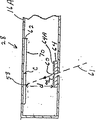
図3は、図2の実施形態で使用するための、基準フレームの好適な実施形態の斜視図である。
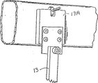
図3Aは、図2の実施形態で使用するための、基準フレームの第二の好適な実施形態の斜視図である。
図3Bは、その上に、図3および図3Aの基準フレーム上を固定することができる、磁気装着部材13Aの分解斜視図である。
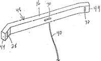
図4は、本発明で使用するためのカメラの斜視図である。
図4Aは、本発明で使用するためのカメラの、第二の実施形態の斜視図である。
図4Bは、本発明内使用するためのカメラの、第三の実施形態の斜視図である。
図5は、車両の基準孔部内に挿入され、その端部上に装着されたクリップを持つプローブの斜視図である。
図6は、車両の基準孔内に挿入されている磁気プローブの斜視図である。
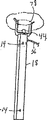
図7は、図5のプローブと同一であるが、より長いプローブの斜視図である。
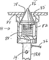
図8は、エミッタが複数の方向を向いている、別のタイプのプローブである。
図9は、クリップ端部の代わりにポインタ・チップを持つ、図7のプローブの斜視図である。この図の場合、プローブは極細線で示す異なる位置に置かれてある。
図10は、上記プローブに追加することができる異なるコネクタを示す、図7のプローブの分解斜視図である。
図11は、車両の基準孔部に挿入した状態の、図6のプローブである。
図12は、図11のプローブの破断断面図である。
図13は、直径がもっと小さい孔部に挿入した状態の、図12のプローブの破断断面図である。
図14は、プローブに追加することができる、アタッチメントのボックスである。
図15は、エミッタからの放射を受けとる、図4Aのカメラの略図である。
図16は、図15のカメラの左端の破断平面断面図である。
図16Aは、図16のコーティングされた帯域フィルタの背面図である。
図17は、エミッタをオンにした場合に、カメラが発生する信号、すべてのエミッタをオフにした場合に、カメラが発生する信号、および結果として周囲の大部分のノイズを除去する、上記二つの信号を引算することにより形成される信号のグラフである。
図18は、測定を開始したときにユーザが見る、図2のタッチ・スクリーンである。
図19は、車両を選択した後でユーザが見る、図2のタッチ・スクリーンである。
図20は、ズレの程度を示す、最初の測定を終了した後の、図2のタッチ・スクリーンである。
図21は、非常に僅かなズレを示す、車両を修理したあとの、図2のタッチ・スクリーンである。
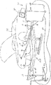
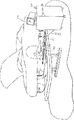
図22は、本発明の装置により測定中の車両のエンジン・ルームおよび乗客ルームの斜視図である。
図23は、図22のユーザが測定した比較測定値を示す図面である。
好適な実施形態の説明
図1は、SAE J1828の車両用の標準基準座標システム5である。この座標システム5は、当業者なら周知のものであり、車両メーカおよび車両用の標準測定データの提供者が使用するものである。座標システムは、三つの直交基準面X、YおよびZを含む。Y面は、自動車を前部と後部とに二分する垂直面である。X面は、車両のほぼ中心を貫通する垂直面であり、Z面は車両のほぼ中心を貫通する水平面である。車両用の記憶済みのデータは、車両上の多くの周知の点のX、Y、Z座標を示す。車両は対称形をしているので、車両の左右の側面上の対応する点は、左の側面上の上記点のY座標が、右の側面上の対応する点と比べると、符号がマイナスになるという点を除けば、同じ座標を持つ。車両はいくつかの基準孔部、基準ボルトおよび他の基準点を持ち、基準点において、標準座標データを入手し、システムに記憶することができる。この基準データは、好適には、車両メーカまたは第三者が提供することが好ましい。別の方法としては、ユーザは、損傷を受けていない、または正しく整合している車両を、本発明のシステムまたは他の何等かの手段により測定し、損傷した車両または整合がズレた車両を測定する前に、そのデータを記憶することによって、自分自身の標準データを確立することもできる。
本発明の測定システムを説明するために、最初に、このシステムの各部およびその個々の機能を説明し、その後で、車両を測定するためにシステム全体の使用方法を説明する。基本的システムは、コンピュータ、ユーザ・インターフェースとしての働きをするタッチ・スクリーン、同様に、ユーザ・インターフェースとしての働きをするキーボード、カメラ、およびカメラにより感知される複数の電磁放射エミッタを含む。
図2および図2Aは、本発明の基本的測定システム10の好適な実施形態である。基準フレーム12は、整合プロセス中動かない車両の一部に固定されている。基準フレーム12は、特定の位置または特定の向きに装着する必要はない。基準フレーム12は、好適には、クランプ13(図3および図3Aに示す)により、車両のピンチウエルドに装着することが好ましいが、車両のフード上に単に載せることもできるし、車両にピンで止め、ボルトで締め付けることもできるし、または他の周知の方法で車両に固定することもできる。図3Bは、ピンチウエルドを持たない車両に対して、使用することができるアダプタ13Aを示す。このアダプタは、磁気的なもので、磁気により車両のフレームまたは他の部分に取り付けられる。クランプ13は、アダプタ上に固定するために使用される。基準フレーム12は、いくつかの異なる方向を向いている、複数の電磁放射エミッタ14を含んでいるので、測定を行うために基準フレーム12が車両の周囲を移動するとき、カメラ16により、この基準フレームを「視野の中に入れること」ことができる。カメラ16(図4により詳細に示す)は、エミッタ14からの電磁放射を感知する三つのセンサ28、30、32を含む。車両24上には、複数のプローブ18が装着されていて、各プローブ18は、少なくとも二つのエミッタ14を含む。(この実施形態の場合、複数のプローブではなく、一つのプローブを使用して、異なる位置で上記の一つのプローブ18により測定をすることもできる。)コンピュータ20は、車両用の標準データを記憶するためのものであり、タッチ・スクリーン22を含み、エミッタ14およびカメラ16と通信する。コンピュータ20には、キーボード25およびプリンタ26が接続している。他のユーザ・インターフェースも使用することができる。コンピュータ20は、動作できるように、各エミッタ14、すなわち、基準フレーム12上のエミッタ14、およびプローブ18上のエミッタ14に接続している。各プローブ18は、基準フレーム12上のボックス27に挿入される電気的ライン36を持ち、電気的バス38は、基準フレーム12からコンピュータ20へ延びる。コンピュータ20は、またバス38により、基準フレーム12のエミッタ14に接続していて、第三の電気的バス40により、カメラ16の電磁放射センサ28、30、32に接続している。以下に、エミッタ14およびセンサ28、30、32について詳細に説明する。上記実施形態は赤外線を使用するが、目で見ることができるものでも、できないものでも、任意の波長の電磁放射を使用することができることを理解されたい。また、好適な実施形態は、あるエミッタを他のエミッタから区別するために、ストロボを使用しているが、異なる周波数の電磁放射を使用したり、または各エミッタ14に対して異なる搬送周波数を使用する他の方法を、あるエミッタ14を他のエミッタから区別するために使用することができる。
図3および図3Aは、本発明の基準フレーム12、12Aの二つの実施形態である。各基準フレーム12、12Aは、車両のピンチウエルドの上、またはアダプタの上にフレーム12、12Aを固定するためのクランプ13を含む。複数のエミッタ14は異なる方向を向いている。カメラ16が測定を行う任意の位置から、基準フレーム12、12A上の少なくとも三つのエミッタ14を「視野の中に入れること」ができるように、エミッタ14を異なる方向に向けることが重要である。基準フレーム12により、コンピュータ20は、カメラ16が基準フレーム12の周囲を移動しても、新しい測定値を既知の座標システム5と関連づけることができる。基準フレーム12上のエミッタ14は、それ自身の上のすべての他のエミッタ14に対して、既知の固定空間的な関係を持ち、コンピュータ20は、基準フレーム12のエミッタ14の間の、固定の空間的な関係を測定することができるように、すでにプログラムされている。
図5−図14は、プローブ18およびプローブ・アタッチメントの種々の図面である。種々の異なる形およびサイズのプローブを使用することができるけれども、二つの異なる長さの標準プローブを使用した場合が、最も効率的であることが分かっている。長い方のプローブ18Aは三つのエミッタ14を持ち、短い方のプローブ18は二つのエミッタ14を持つ。これら短い方のプローブの二つのエミッタは、長い方のプローブ18Aの最初の二つのエミッタ14が、短い方のプローブ18の端部に対するように、その端部に対して同じ位置関係にある。図10に示すように、プローブ18Aは、一方の端部にネジ山付きの孔部19を持ち、この孔部19には、コネクタ41、44、アダプタ46、またはポインティング・チップ42を取り付けることができる。短い方のプローブ18の接続端部は、同じもので、同じアタッチメントを受け入れる。
図9は、(図10に示す)孔部19内にネジこまれた針またはポインティング・チップ42付きのプローブ18Aである。各プローブ18、18Aは、ケーブル36の端部の、電気的コネクタ35Aを接続するための、電気的ソケット35を持つ。ライン36の他方の端部は、図2、図2D、図3および図3Aに示すボックス27内に挿入される。ポインタ・チップ42は、ボルトの中央に接触している。このチップ42により、プローブ18Aを手持ちプローブとして使用することができる。何故なら、このチップは、車両上のある位置に簡単に置いたり、置き放しにすることができないからである。しかし、このタイプのプローブの利点は、車両の本体上部の任意の場所を含めて、車両上の任意の場所に置くことができるし、プローブ18Aを任意の方向に向けることができることである。図2Aは、ドア・フレームの一点を測定するために、このタイプの手持ちプローブを使用している人の様子を示す。図22は、運転室およびエンジン・ルーム内の、いくつかの点を測定するために、このタイプの手持ちプローブを使用する人の様子を示す。これらの点は測定するために測定点をある平面まで下げるための、機械的フレームを使用する、他のタイプの車両測定システムでは、測定するのが非常に困難であるか不可能である。
エミッタ14の位置と、プローブ18の端部47の位置との間には、一定の関係があるので、コンピュータがエミッタ14の位置を決定すると、コンピュータは、プローブ18Aで測定中の点47の位置を決定することができる。ポインティング・チップ42は、通常、長い方のプローブ18Aにより使用されるので、プローブ18Aのエミッタ14の、どれか一つをチェックすることができない場合でも、コンピュータは、プローブ18A上の他の二つのエミッタ14を「視野の中に入れること」によって、プローブ18Aにより測定中の点の位置を決定することができる。図14のトリガ43を持つライン36は、通常、ポインタ42を使用する場合には、ユーザが現在行っている測定を離れた場所から制御できるように、普通のライン36に代わりに使用される。
異なるタイプのプローブまたは端部コネクタに対する、プローブ18Aにより測定中の点に対する、エミッタ14の相対的位置が異なる場合には、コンピュータ20は、オペレータに特定の点を測定するのに、どのタイプのプローブまたは端部コネクタを使用すべきかを指定し、その後で、コンピュータはその計算を行っている際に、上記異なるタイプのプローブまたは端部コネクタの補償を行う。
図10は、アレン・ネジにより、プローブ18Aの端部上に保持されている、スプリング・クリップ・コネクタ44である。上記スプリング・クリップ・コネクタ44は、図14に示すように、車両上の基準孔部のサイズに対応して、非常に種々のサイズのものがある。各コネクタ44には、A、B、C等のような文字が付けられていて、コンピュータ20は、車両上のどの基準孔部を測定するには、どのコネクタ44を使用すべきかについてユーザに指示を与える。すべてのクリップ・コネクタ44の大きさは、好適には、測定中の点が、プローブ18のエミッタ14に対して、何時でも同じ位置に位置するようなものであることが好ましい。(これは必ずそうでなければならないというものではないが、コネクタの大きさを上記のようにすることにより、必要な計算の回数が少なくなる。)図5および図10のクリップ・コネクタ44は、湾曲したチップ77が付いている柔軟なプロング76を持つ。クリップ44は、プローブ18Aを、孔部78の中心に設置する働きをする。外側に湾曲しているチップ77は、クリップ44の肩部79のプロング76から急に突出していて、また上記肩部79は、車両の表面に常に位置していて、そのため、個々のエミッタ14の位置が分かっていて、またプローブ18Aの大きさが分かれば、コンピュータは、プローブ18Aが位置する孔部78の中心の位置を容易に決定することができる。
図14のボックスの底部の右の部分に位置する、スプリング・クリップ・コネクタ44の中のいくつかは、内側を向いていて、ナットまたはボルトを掴むことができる端部を持つ。
図10は、またプローブ18A内の孔部19に装着し、孔部19に対して直角なネジ山付き孔部19Aを持つ、直角アタッチメント46である。そのため、クリップ・コネクタ44またはポインタ端部42を、プローブ18に対して直角に装着することができる。直角アタッチメント46を使用する場合には、コンピュータは補償を行わなければならない。何故なら、このアタッチメントは、エミッタ14に対して、測定点を少しシフトさせるからである。コンピュータは、この補償を行わなければならないとき、または任意の他のの必要な補償を行わなければならないときを知っている。何故なら、コンピュータは、そのソフトウェアの「ツール・ファイル」に記憶している、すべてのプローブおよびコネクタについての情報を持っているからである。何故なら、コンピュータが、測定対象の各点に、どのタイプのコネクタおよびクリップを使用するのかについて、ユーザに指示を与えているからである。好適な実施形態の場合には、一番端のエミッタ14から現在測定中の点までの距離は、すべてのプローブおよび大部分のアタッチメントに対して同じであり、エミッタ14は、現在測定中の点と直接一直線上にある。
図6、図11、図12および図13は、プローブ18、18Aの、ネジ山付き孔部19内にネジ込むことができる、磁気アタッチメント41である。この磁気アタッチメント41は、平らな端部84付きの中空の磁気本体82を持つ。円錐形部材86は、磁気本体82の内側に装着されていて、平らな端部84内の開口部83を通して突出している。円錐形部材86は、スプリング88によりスプリング装着されている。この磁気アタッチメント41が、車両24の孔部78内に装着されると、平らな端部84は、何時でも車両24の面上に乗り、円錐形86は、それが孔部の中心にプローブ18Aがくるように、十分深く孔部内に突出する。図12は、大きな孔部内に深く突出している円錐形を示し、図13は、小さな孔部内に短い距離だけ突出している円錐形86を示す。円錐形がどれだけの長さ孔部内に突出していようとも、現在測定中の点と上記平らな面84との間の関係は、何時でも一定であるので、コンピュータは、何時でも、プローブ18A(または18)上の、エミッタ14に対する測定点の位置を知ることができ、それにより、プローブ18Aにより現在測定中の点を計算することができる。
図2、図2A、図2B、図2C、図2D、図4、図4Aおよび図4Bは、本システム10で使用することができる種々のカメラ16、16A、16B、16Cである。各カメラ16、16A、16B、16Cは、好適には、相互に一定の関係で装着されている、少なくとも三つのセンサ28、30、32を持つことが好ましい。センサ装置28、30、32は、好適には、電荷結合素子(CCD)のような、二つの一次元電磁放射センサからなることが好ましい。図4のカメラ16は、ほぼ45度の角度で内側に曲がっている二つの端部49を持つ、ほぼ水平なブーム48である。ブーム48は、好適には、図2に示すように、車輪52付きのスタンド50上に装着することが好ましい。(カメラ16−16Cの中のどれでも、スタンド50上に同様の方法で装着して、使用することができる。)スタンド50は、いくつかの調整ノブ54を持ち、それによりカメラ16を、任意の好きな高さおよび角度に、設定することができる。また車両を任意の好きな位置から見るために、工場内を車輪によりスタンド50を移動させることができる。
図4のカメラ16の場合には、センサの中の一つ30が、水平スリットの後のブーム48の中心に位置していて、他の二つのセンサ28、32は、垂直スリットの後のブーム48の端部49上に位置している。(「垂直」および「水平」という用語は、相対的な用語で、本明細書においては、単に説明を分かりやすくするために使用する。)ブーム48を、図に示すように、水平方向に向ける必要はない。それ故、ブーム48の向きに従って、種々の方向に向けることができる。また、カメラ16Bおよび16C内に示すように、スリットを相互に垂直に配置する必要もない。スリットすべてが同軸になりさえしなければよいのである。何故なら、スリットは、現在測定中の点の位置を決定するために、三つの交差する平面を決定しなければならないからである。
図4Aのカメラ16Aの場合には、ブーム48Aの端部は曲がっていないで、まっすぐになっている。これにより、カメラ16Aは、より長い距離を楽に感知することができるので、このほうが好ましい。図4Bのカメラ16Bの場合には、外側のスリットは、中心のスリットに対して45度の角度を持っている。図2Dのカメラ16Cの場合には、カメラ16Cはピラミッドの形の本体を持ち、スリットは上記ピラミッドの各面上において、相互に60度の角度を持っている。
図4のカメラ16上の三つのセンサ・ユニット28、30、32は、カメラ16内でのその位置を除けば、互に同じものである。すなわち、センサ28、32は、垂直スリットの後で水平方向を向いているが、中央のセンサ30は、水平スリットの後で垂直方向を向いている。すべてのカメラ16−16C内の、すべてのセンサ28、30、32は、そのそれぞれのスリットの方向で直交していなければならない。以下にセンサ28について詳細に説明する。他のセンサ30、32がそれぞれのスリットに直交した状態で、同じ方法で機能することを理解することができるだろう。
図15および図16に示すように、センサ28は、カメラ16Aの主軸に沿った方向を向いている。説明の便宜上、この向きを水平方向と呼ぶことにする。ガラス板64が、カメラ・ハウジング16Aの、前部のおよび光検出機構62の前部の内面上に位置していて、帯域フィルタとしての働きをし、狭い幅の電磁放射だけがそこを通ることができ、それにより、周囲ノイズの多くが除去される。この場合、エミッタから現在放射される好適な電磁放射は赤外線であるので、帯域フィルタは、赤外線だけを通過させることができる。エミッタ14は、好適には、赤外線を放射する発光ダイオードであることが好ましい。エミッタ14が、異なる波長の電磁放射を放射している場合には、帯域フィルタ64は、必要な波長だけを通過することができるように選択される。細長い垂直スリット60は、帯域フィルタ64の背面上の、コーティング64A内の細長い垂直の、割れ目により形成される。図16および図16Aがスリットを示す。この垂直なスリット60により、エミッタ14からの電磁放射の垂直面61だけが、センサ28のリニア光検出機構62に達することができる。また、カメラ16Aは、そこから測定中のエミッタ14を「視野の中に入れること」ができる、任意の位置に設置することができることに留意されたい。それ故、スリット60内に入る電磁放射61の面は垂直ではなく、スリット60がどのような位置にあろうとも、スリット60と整合する。リニア光検出機構62は、好適には、その上に入射した電磁放射の存在および強度を感知する、幅約1ピクセル、長さ3700ピクセルの、電荷結合装置(CCD)であることが好ましい。リニア光検出機構62は、その長い軸がスリット60と直交するように位置している。
エミッタ14からの電磁放射の面61は、スリット60および帯域フィルタ64を通過し、光検出機構62上に入射する場合には、上記面は、リニア光検出機構62の面70上に実像ライン58を形成する。光検出機構62は、その後、実像ライン58の位置を特定する働きをする、その面上に受信した電磁エネルギーの位置、および強度に関連する出力を発生する。実像ライン58により照射された、光検出機構62のこれら素子、すなわち、ピクセルは、強力な信号を発生する。一方、照射されなかった光検出機構62は、非常に弱い信号を発生するか、または全然信号を発生しない。画像強度または信号強度のグラフは、図17に示すように、信号ピーク曲線66である。曲線72は、エミッタ14がオンになったときの、光検出機構62からの信号を示す。曲線68は、すべてのエミッタ14がオフになった場合の、光検出機構62からの信号を示す。曲線74は、曲線72から曲線68が引算され、それにより周囲ノイズの大部分が除去された場合の合成曲線を示す。ライン80は、それ以下の信号が無視される閾値を表わす。
すべてのエミッタがオフになった場合にも、周囲の電子ノイズのために、信号レベルが、決して全くゼロにならないことに留意されたい。ノイズが全然ない場合には、光検出機構62上の実像ライン58の位置は、信号72から決定することができる。しかし、好適には、図に示すように、背景ノイズを差し引き、大部分の背景ノイズがすでの除去されている、合成曲線74を使用して、実像ライン58の位置を決定することが好ましい。背景ノイズを差し引くために、好適には、出力信号をデジタル・メモリ内に記憶することが好ましい。その後、すべてのエミッタを瞬間的にオフにした場合の測定値が、現在点灯しているエミッタ14が発生したデータを入手するために、現在のデータから差し引かれる。二つの測定値72、68は、本質的には、実像58の位置のところだけで異なり、この差は、域値レベル80を越える。それ故、画像58の位置を容易に決定することができる。曲線74から読み取った通常の測定値は、下記のいずれかである。(1)ピーク輝度を持つ個々の光検出機構素子の位置、(2)閾値を越えたすべての素子の輝度加重平均、または(3)輝度がある閾値を越える最小素子および最大素子の平均。
光検出機構62の表面70からスリット60までの距離dと、スリット60のすぐ背後に位置する、光検出機構62の中心cからのライン58の変位距離が分かれば、コンピュータ20は、面61がセンサ28上に入射する角度αを計算することができる。点58が決定されると、角度αは容易に計算することができる。それ故、この時点に於て、コンピュータは、エミッタ14から、第一のスリット60の中心までの面61を形成している角度αが分かる。カメラ16上の他のセンサ30、32は、類似の測定を行っているし、コンピュータ20は、カメラ16内でのセンサ28、30、32の、相対的位置を知っているので、コンピュータ20は、エミッタ14が含まれる三つの面を知る。これら三つの面の交差により、カメラ16に対するエミッタ14の位置である、空間内の一点を決定する。コンピュータ20が、固定座標に対するカメラ16の位置を知っている場合、またはカメラ16が、固定座標システム5内のその位置を知っている、基準エミッタ14の位置を感知している場合には、コンピュータ20は、エミッタ14の計算した位置を、固定座標システム5に換算することができる。
三つのセンサ28、30、32は、好適には、各センサが、空間内での正確な位置を知りたい、照明を受けているエミッタ14から、ほぼ等距離になるように、一本の直線または円弧に沿って配置することが好ましい。センサ28、30、32が、カメラ16および16A内のように、水平円弧に沿って配置された場合には、中央のセンサ30は、照明エミッタ14の仰角を測定するような方向を向いている。二つの外側のセンサ28、32は、水平角を測定する。(ここでもまた、水平および垂直という用語を使用するのは、説明を分かりやすくするためのものであって、カメラを、感知対象のエミッタを「視野の中に入れること」ができる、任意の位置を置くことができることを理解されたい。)三つのすべてのセンサ28、30、32は、測定対象の照明を受けているエミッタ14が、その視野内に完全に入るように、設置しなければならない。図2Dのカメラ16C内でのように、視野の範囲を広げたり、または測定の解像度および精度を改善するために、追加のセンサを使用することができる。しかし、カメラが測定を行うために対象物の周囲を移動することができる場合には、精度の高い測定を行うには、三つのセンサで十分であることが分かっている。
コンピュータ20の構造および動作、特にその制御システムについて以下に詳細に説明する。コンピュータの制御システムは、エミッタ14に電力を供給し、エミッタを既知の間隔でストロボ発光させる。コンピュータ制御システムは、また電磁放射センサ28、30、32にも電力を供給する。センサ28、30、32からの角度データ信号は、コンピュータ20が受信し、コンピュータ20は、すべてのエミッタ14をオフにしたときに測定した背景ノイズ68を、またエミッタ14をオンにしたとき測定した背景ノイズを、データ72から差し引き、ほとんどのノイズが除去された結果74を入手する。このデータは、カメラ・スリットからエミッタ14への角度αを決定するために使用され、その後、三角測量により、カメラ16に対するエミッタ14の位置の計算が行われる。プローブ18の場合には、コンピュータ20は、プローブにより現在測定中の点の位置(すなわち、クリップ44または磁気コネクタ41が位置している孔部の中心、またはニードル・プローブ42の先端)を計算するために、プローブのエミッタ14の位置、およびプローブ18の既知の構成を使用する。その後、この位置は、固定標準座標システム5に関連付けられる。
コンピュータが、上記データを、固定座標システム5の関連づけることができる基準点は、いくつかの方法で供給することができる。図2および図2Aに示す好適な方法は、整合プロセス中動かない車両の位置に対する基準フレーム12を固定し、コネクタ41または44付きの少なくとも三つのプローブ18を、標準測定データを入手することができる車両の、損傷を受けていない部分上に設置する方法である。その後、基準フレーム12上のエミッタ14の位置と、既知の車両の損傷を受けていない点内の、プローブ18上のエミッタ14の位置との間の関係を知ることにより、測定が行われ、車両の記憶済みの、固定座標システム5に対する、基準フレーム12の位置が確立される。その後、新しい測定を行う必要がある場合に、基準フレーム12からのエミッタ14を、視野内に捕らえることができる限りは、コンピュータ20は、これら新規に測定した点を、固定座標システム5と関連づける。コンピュータが、少なくとも三つの基準点からデータを受信しなかった場合には、コンピュータは、新しく測定した点を、固定座標システム5と関連付けることができないので、その結果、データは戻らず、スクリーン22上に赤いインジケータが表示され、ユーザにカメラ16をもっとよい位置に、移動しなければならないことを知らせる。センサ28、30、32が、プローブ18上の少なくとも二つのエミッタ14から、信号を感知できなかった場合には、そのプローブに対してデータは戻されず、スクリーン22上に赤いインジケータが表示され、ユーザにプローブを視野の中に入れることができないことを知らせる。
基準点を供給するもう一つの方法は、図2Cに示すように、整合プロセス中動かない、車両の損傷を受けていない部分内に、固定プローブ18を設置する方法である。固定プローブ18は、全測定プロセス中正しい位置から移動しないで、車両に対して固定され、固定プローブは、全体で基準フレーム12を形成する。好適には、固定プローブ18は、測定を行いながら、それ自身が車両の周囲を移動する場合、カメラ16、16Aまたは16Bが、エミッタ14を「視野の中に入れることが」できるように、異なる方向を向いていることが好ましい。図8は、このタイプの基準フレーム12C内で使用するための、好適な固定プローブ18Bの一例を示す。このプローブ18Bは、少なくとも二つの側面上にエミッタ14を持ち、好適には、四つのすべての側面上にエミッタ14を持つことが好ましい。固定座標システム5に対する基準エミッタ14の位置が確立すると、コンピュータ20は、基準エミッタ14の少なくとも三つを、新しい測定が行われている同じカメラ位置から見ることができる限り、新しく測定した点を、固定座標システム5に関連づけることができる。
基準エミッタ14を設置するもう一つの方法は、図2Bに示すように、車両の周囲に個々のエミッタ14を単に取り付けて、それにより、基準フレーム12Bを形成する方法である。カメラ16は、その後、車両の周囲を移動し、種々の固定基準エミッタ14を感知し、エミッタ14の間の相対的位置を確立する。その後、基準エミッタ14の中のいくつかの測定が行われる、同じカメラ位置から既知の点を測定するために、一つまたは複数のプローブ18が使用され、それにより、基準エミッタ14と、固定座標システム5との間の関係が確立する。この関係が確立すると、新しい点の測定が行われる同じカメラ位置から、基準エミッタ14の中のいくつかが測定される限り、カメラ16は、測定を行うために車両の周囲を移動することができ、その後コンピュータ20により、上記新しい点は、標準座標システム5と関連づけられる。
図2Dに示すように、第四の方法は、整合プロセス中動かない車両のある部分に対して、カメラを固定する方法である。この場合、カメラに対する車両上の既知で損傷を受けていない点の位置が確立されると、固定座標システムに対するカメラの位置が確立され、その後、コンピュータ20により、カメラにより行われた新しい測定値を、固定座標システムに関連づけることができる。この実施形態の場合には、好適には、ピラミッド形のカメラ16Cを使用することが好ましい。何故なら、このカメラは視野が広いからである。しかし、その固定位置から測定対象の点を「視野に入れること」ができる限り、任意のカメラを使用することができる。
車両を測定するために上記装置を使用する場合には、ユーザには下記のステップを行う。
最初に、ユーザは測定プロセスを開始するように指示している、図18に示すタッチ・スクリーン類似のタッチ・スクリーン22が表示される。コンピュータ20は、タッチ・スクリーン22により、どのタイプの車両を測定するのかを質問してくる。ユーザは、タッチ・スクリーン22に触れるか、またはキーボード23または他のユーザ・インターフェースを使用して、測定対象の車両の造りおよびモデルを選択する。その後、コンピュータ20は、図19に示すように、車両のそのタイプの一組の標準図面を示す、そのタイプの車両24に対する、記憶済みの標準測定データにアクセスする。その後、ユーザが図2および2Aの実施形態を使用している場合には、好適には、車両のピンチウエルド上にフレーム12を固定するのが好ましい、整合プロセス中動かない車両の一部に対して、基準フレーム12または12Aが固定される。
その後、ユーザは、図19のタッチ・スクリーンに触れ、車両の損傷を受けていない部分に対応する既知の点を表示し、コンピュータ20は、ユーザに上記既知の点に接続されるプローブ18に、どのコネクタまたはアダプタを接続すべきかを指示する。ユーザはコンピュータの指示に従い、プローブ18を選択した基準孔部に挿入するか、またはそうしない場合には、プローブ18を選択した基準点に接続する。ユーザが、順次、プローブ18を車両上の複数の基準点に接続する場合、上記プロセスが反復して行われる。
その後、カメラ16は、基準フレーム12上のエミッタ14、および既知で損傷を受けていない点に設置された、プローブ18上のエミッタの測定を行う。基準フレーム・エミッタ14と、プローブ・エミッタ14との間の空間的な関係を決定することによって、またプローブ・エミッタ14と、車両に対する固定座標システム5との間の関係を知ることによって、コンピュータ20は、基準フレーム12のエミッタ14の位置を、車両用の固定座標システム5に関連付ける。その後、プローブ18は、その場所にそのまま留まることもできるし、測定対象の他の位置に移動することもできる。その後、ユーザは、タッチ・スクリーン22に触れて、測定対象の他の点を選択することもできるし、標準データを利用することができない、車両上の任意の点を測定するために取り付けられている、ニードル・チップ42およびトリガ43を備える、手持ちプローブ18を使用することができる。トリガ43は、好適には、ニードル・チップ42が接続している、プローブ18に接続することが好ましい。トリガ43は、プローブ18からボックス27まで一直線36に延びていて、ユーザは、自分がニードル・チップ・プローブ18を使用して、測定を行いたい場合には何時でも、トリガ43を押すことができる。標準データを利用することができない場合でも、ユーザは測定中の各点に対する、固定座標システム5の三つの座標の数値を受けとることができ、車両の左右の側面上の、対称的な対応する点の位置を比較することによって、整合を行うために、損傷を受けた側面を、どの程度矯正させなければならないかを決定する。
ユーザが車両上の既知の点を測定している場合には、図20に示すように、スクリーン22は、偏差の方向と程度を示すベクトルと、偏差の程度および方向を示す数値の両方で、測定点の標準データからの偏差の程度を示す。ベクトルの長さは、好適には、記憶済みのデータ点からの測定点の偏差の対数に比例することが好ましく、それにより、大きい偏差および小さい偏差の両方を、グラフで示すことができる。このことは、ユーザにとって非常に便利である。何故なら、上記画グラフは、ユーザに、車両の整合を行うために必要な移動方向を正確に示し、また必要な矯正の程度を示すからである。ユーザがグラフをハッキリと見ることができるように、車両の運転手側のベクトルは、乗客側のベクトルとは異なる色で表示される。
元の一組の測定値は、コンピュータ20に記憶することができ、車両を修理する前に、損傷または整合のズレの程度を表示するために、プリンタ26により印刷することもできる。
基準フレーム12Cを確立するために、固定プローブ18を使用する場合には、図2Cに示すように、固定プローブ18または18Cが、整合プロセス中動かない車両上の既知の損傷を受けていない位置に位置しているという点を除けば、同じ手順が行われる。その後、カメラ16が測定を行う度に、カメラ16は、新しい測定点と、固定プローブ18上の既知のエミッタ14の位置との間の関係を確立し、コンピュータ20は、新しい測定点を固定座標システム5に関連づけることができる。
基準フレーム12Bを確立するために、個々のエミッタ14を使用する場合には、図2Bに示すように、テープまたは糊またはベルクロ▲R▼または他の固定手段により、エミッタ14が車両上に固定される。カメラ16は車両の周囲を移動し、測定を行い、エミッタ14の位置を相互に関連づける。プローブ18により、既知の点が測定され、車両上に固定されたエミッタ14に関連づけられる。その後、固定エミッタ14の位置が、固定標準座標システム5に対して確立される。その後、新しい測定が行われる場合には、カメラ16は、新しい点を測定する場合、同じカメラ位置から既知の固定エミッタ14を測定し、それにより、コンピュータ20は、新しい点を、固定座標システム5に関連づける。
カメラ16が、車両の損傷を受けていない部分に対して、固定されている場合には、図2Dに示すように、車両上のいくつかの既知の点を測定するために、プローブ18を使用し、それにより、固定カメラ16Cと固定標準座標システム5との間の関係を確立し、その後、固定カメラ16Cにより他の測定が行われる度に、コンピュータ20は、新しい点の位置を、固定座標システム5と関連付ける。固定カメラ16−16Cは、対象とする測定を「視野の中に入れること」ができる、任意の固定点に設置することができる。
ストロボの速度は、センサ28、30、32が、すべての実際上の目的のために、測定中の点の位置および方向を瞬間的に決定し、その情報をユーザ・インターフェース22を通して、ユーザに知らせることができるだけの十分な速さを持っている。ここでもまた、センサ28、30、32は、どのエミッタ14が、任意の時点で照明されたかを区別するだけでよい。本発明の好適な実施形態の場合には、この機能は、一回に一度エミッタ14を、ストロボ発光または電力供給することにより実行される。しかし、センサ28、30、32が、各エミッタ14を相互に区別することができる、他の方法も使用することができる。例えば、各エミッタにより、異なる波長の電磁エネルギーを放射することができ、これら特定の周波数を区別することができる、光検出機構を使用することができる。別の方法としては、各エミッタ14を、各エミッタ14用の一意の波形パターンで、変調することもできる。その後、その位置信号が、どの特定のエミッタ14に属するものかを決定するために、上記一意の波形パターンを復調するように、コンピュータ20をプログラムすることができる。あるエミッタ源を、他のエミッタ源から区別するための他の方法も使用することができ、本発明に適用することができる。しかし、本明細書に記載した単一の赤外線光学システムは、適当なレベルの性能を発揮する。エミッタ14の実像の焦点が多少ぼけていても、その実像の角度測定を依然として使用することができる。
それ故、車両上の任意の固定基準点の他に、移動している点上に装着されたプローブ18を使用して、ユーザは車両の整合を始める。車両が整合した場合、ベクトルは短くなり消失し、ユーザが図21に示す位置に類似の位置に到着するまで、整合のズレの程度を示すスクリーン22上の数字は減少を続ける。これが「後」測定で、この測定値は、再びコンピュータ内に記憶することができ、車両を整合、または修理した程度のデータとして印刷することができる。
図22は、他のシステムでは実行することが困難か不可能であるが、測定中の点についての標準データを使用できない場合でも行うことができる、本発明により実行することができる有用なタイプの測定を示す。この場合、ユーザは、ポインティング・チップ42を備える手持ちプローブ18を、車両のエンジン・ルーム内の四つの点1−4、および運転席内の二つの点5−6に向ける。相互に対向している点1および3は、同様に、相互に対向している点2および4の場合のように、座標システム5に対して、ほとんど同じ幅、長さおよび高さの測定値を持つ。また、点3および4の間の対角線の長さ「a」は、点1および2の間の対角線の長さ「b」と同じである。同様に、相互に対向している点5および6は、ほとんど同じ測定値を持つ。標準的な方法では点5および6の間の距離を測定するのは非常に難しい。何故なら、車両が測定の邪魔になるからである。しかし、本発明を使用すれば、このタイプの測定を非常に簡単に行うことができる。図23は、図22で行った比較測定を示す。実際、距離「a」および「b」は同じであり、相互の直接対向している点は、ほとんど同じ測定値を示す。
当業者であれば、本発明の範囲から逸脱することなしに、上記本発明の実施形態を修正することができる。 Background of the Invention
The present invention claims priority from US Provisional Application No. 60 / 026,195, filed Sep. 16, 1996. The present invention relates to a vehicle measurement system.
Many instruments have been built on the vehicle to date to determine how much the vehicle frame should be corrected after an accident, or to determine how much the vehicle wheels or other parts should be aligned. Have been used. Mechanical measuring instruments were difficult to use. In the case of mechanical measuring instruments, the user must have considerable knowledge, take time to use and do not get the required accuracy. Other devices use sound waves to measure the position of points on the vehicle and measure the passage of time from when the sound waves were fired until they reached multiple sensors. The system has many problems with external noise in factory air hoses and other devices that adversely affect sensor readings. These systems also have accuracy problems. This is because the speed at which sound waves propagate depends on the weather and also on the speed of the air moving through the factory. Other devices use a target that is mounted on the vehicle and scan the vehicle with a laser or other beam to measure the position of the target. In these systems, all targets need to be coplanar, which is very cumbersome and time consuming. To date, there has been no system for measuring the degree of alignment deviation or the deviation of the measured value from the standard value which is highly accurate and easy to use.
Schulz US Pat. No. 5,622,170 discloses a measuring instrument used in the medical field to track the position of a probe within a patient during an open surgical procedure. The system is not suitable for measuring the deviation of a vehicle from a reference value, but has several features similar to those of the present invention. The above patents are incorporated herein by reference.
Summary of the Invention
The present invention provides a system that solves many of the problems of prior art vehicle measurement systems. The system of the present invention can be used in a short time, is easy to use, requires only a simple education for the user, and has a very high accuracy. The system also essentially provides information to the user in real time, so that the user can measure the vehicle standard values while correcting the frame and aligning the wheels or other parts of the vehicle. It can be checked that the deviation from the standard value is corrected until they match.
When compared to other vehicle measurement systems, one important advantage of the present invention is that all users on the vehicle, including any point on the top of the vehicle body, can be simply touched with a probe by the user. The point can be measured. As with prior art systems, it is not necessary to create a careful framework to pull the measurement point down to a reference plane.
The present invention uses a camera including an electromagnetic radiation emitter fixed relative to the vehicle, a movable probe having a plurality of electromagnetic radiation emitters, and a plurality of electromagnetic radiation sensors to measure the vehicle. A computer controls the emitter, receives data from the sensor, calculates the position of the emitter relative to the sensor, associates the position with the stored reference data for the vehicle, and associates the measurement points with the stored reference coordinates for the vehicle Compare with the system.
The camera can move around the vehicle to measure points at various locations on the vehicle. This is a significant improvement over the conventional system. In the case of the conventional system, all the points to be measured have to be detected by a sensor installed at one position. Whenever the camera moves to a new position, the camera must be able to “put into the field of view” several points at a known position from the same point that measures the new point. As a result, the computer can associate the position of the new point with a known coordinate system.
The sensor is preferably mounted on a single boom or camera so that its relative position does not change. A slit is placed in the front of the sensor so that the sensor can receive one face of electromagnetic radiation and measure the angle from the emitter to the sensor from there. By determining three intersecting planes with the sensor, the intersection of these three planes becomes the position of the emitter relative to the camera. This process is called triangulation.
Preferably, the emitters are illuminated with a strobe and time multiplexed so that only one emitter is turned on and sensed at a time. The computer controls the strobe and receives data from the sensor. In addition, since the computer knows the flash time, the computer also knows which emitter data is being received. The strobe fires so quickly that in practice, the user obtains data in real time while the vehicle is being repaired and aligned.
The computer includes a touch screen user interface, and when the measurement is being performed, the screen shows the deviation of the measurement point from the standardized value. Deviations are indicated both graphically and numerically, and when displayed, vector lines extend from the drawing showing each standard point being measured. The vector extends in the direction of deviation and has a length corresponding to the magnitude of the deviation. Therefore, the user only needs to look at the screen to know the exact direction that the point must be moved in order to align correctly, and the user needs the amount of correction required to perform the alignment. Has a visual display to show The vector line moves while the vehicle is being repaired, so when the vehicle is fully aligned, the user will see the vector line shorten and disappear.
Multiple reference emitters must be oriented in different directions. As such, when the camera moves around the vehicle to measure various points on the vehicle, the camera can "put" a plurality of reference emitters into view at any time. The plurality of reference emitters can be located on a probe mounted on the vehicle, can be mounted directly on the vehicle, or can be installed on a frame that is fixed to the vehicle. .
In other embodiments, the camera can be fixed relative to the vehicle at a position from which all points to be measured can be “entered into the field of view”.
[Brief description of the drawings]
FIG. 1 is a perspective view of a standard vehicle coordinate system from SAE J1828.
FIG. 2 is a perspective view of a preferred embodiment of the present invention.
FIG. 2A is a side view of the embodiment of FIG. 1 showing connections from individual components of the measurement system to a central computer.
FIG. 2B is a perspective view of the first other embodiment of the measurement system of the present invention.
FIG. 2C is a perspective view of a second other embodiment of the measurement system of the present invention.
FIG. 2D is a perspective view of a third other embodiment of the measurement system of the present invention.
FIG. 3 is a perspective view of a preferred embodiment of a reference frame for use in the embodiment of FIG.
FIG. 3A is a perspective view of a second preferred embodiment of a reference frame for use in the embodiment of FIG.
FIG. 3B is an exploded perspective view of the magnetic mounting
FIG. 4 is a perspective view of a camera for use with the present invention.
FIG. 4A is a perspective view of a second embodiment of a camera for use with the present invention.
FIG. 4B is a perspective view of a third embodiment of a camera for use within the present invention.
FIG. 5 is a perspective view of a probe having a clip inserted into the reference hole of the vehicle and mounted on its end.
FIG. 6 is a perspective view of the magnetic probe inserted into the reference hole of the vehicle.
FIG. 7 is a perspective view of a longer probe that is the same as the probe of FIG.
FIG. 8 is another type of probe with the emitter pointing in multiple directions.
FIG. 9 is a perspective view of the probe of FIG. 7 with a pointer tip instead of the clip end. In the case of this figure, the probes are placed at different positions indicated by fine lines.
FIG. 10 is an exploded perspective view of the probe of FIG. 7 showing different connectors that can be added to the probe.
FIG. 11 shows the probe of FIG. 6 in a state inserted into the reference hole of the vehicle.
12 is a cutaway sectional view of the probe of FIG.
FIG. 13 is a cutaway cross-sectional view of the probe of FIG. 12 in a state of being inserted into a hole having a smaller diameter.
FIG. 14 is a box of attachments that can be added to the probe.
FIG. 15 is a schematic illustration of the camera of FIG. 4A receiving radiation from an emitter.
16 is a cutaway plan sectional view of the left end of the camera of FIG.
FIG. 16A is a rear view of the coated bandpass filter of FIG.
Figure 17 shows the two signals above that remove the signal generated by the camera when the emitter is turned on, the signal generated by the camera when all emitters are turned off, and the result of most of the surrounding noise. 4 is a graph of a signal formed by subtracting signals.
FIG. 18 is the touch screen of FIG. 2 that the user sees when starting the measurement.
FIG. 19 is the touch screen of FIG. 2 as seen by the user after selecting a vehicle.
FIG. 20 is the touch screen of FIG. 2 after finishing the first measurement showing the degree of misalignment.
FIG. 21 is the touch screen of FIG. 2 after repairing the vehicle, showing very slight misalignment.
FIG. 22 is a perspective view of the vehicle engine room and passenger room being measured by the apparatus of the present invention.
FIG. 23 is a diagram showing comparative measurement values measured by the user of FIG.
DESCRIPTION OF PREFERRED EMBODIMENTS
FIG. 1 is a standard reference coordinate
In order to describe the measurement system of the present invention, first, each part of the system and its individual functions will be described, and then how to use the entire system to measure the vehicle. The basic system includes a computer, a touch screen that serves as a user interface, as well as a keyboard that serves as a user interface, a camera, and a plurality of electromagnetic radiation emitters sensed by the camera.
2 and 2A are preferred embodiments of the
3 and 3A are two embodiments of the
5-14 are various views of the
FIG. 9 is a
Since there is a fixed relationship between the position of the
If the relative position of the
FIG. 10 is a
Some of the
FIG. 10 also shows a
FIGS. 6, 11, 12 and 13 show a
2, 2A, 2B, 2C, 2D, 4, 4A and 4B are
In the case of the
In the case of the
The three
As shown in FIGS. 15 and 16, the
When the surface 61 of electromagnetic radiation from the
Note that even if all emitters are turned off, the signal level will never be zero due to ambient electronic noise. If there is no noise, the position of the
If the distance d from the
The three
The structure and operation of the
The reference point with which the computer can associate the data with the fixed coordinate
Another way of providing a reference point is to place a
Another way to install the
As shown in FIG. 2D, the fourth method is to fix the camera to a certain part of the vehicle that does not move during the alignment process. In this case, once the position of a known undamaged point on the vehicle relative to the camera is established, the position of the camera relative to the fixed coordinate system is established, after which the
When using the device to measure a vehicle, the user performs the following steps:
Initially, a
The user then touches the touch screen of FIG. 19 to display a known point corresponding to the undamaged portion of the vehicle, and the
The
When the user is measuring a known point on the vehicle, as shown in FIG. 20, the
The original set of measurements can be stored in the
When using the fixed
When using
If the
The speed of the strobe is determined by the
Thus, in addition to any fixed reference point on the vehicle, the user initiates vehicle alignment using a
FIG. 22 is a useful type that can be performed by the present invention that can be performed even when other systems are difficult or impossible to perform, but can be performed even when standard data about the point being measured is not available. Show the measurement. In this case, the user points the hand-held
Those skilled in the art can modify the above-described embodiments of the present invention without departing from the scope of the present invention.
Claims (13)
車両に対して固定でき、基準エミッタ信号を供給することができる複数の基準エミッタと、
車両上の少なくとも一つの選択した点に移動させることができ、プローブ・エミッタ信号を供給するための少なくとも二つのプローブ・エミッタを含む少なくとも一つのプローブと、
前記基準エミッタ信号と前記プローブ・エミッタ信号とを受信し、基準およびプローブ・エミッタ位置データ信号を供給するための少なくとも三つのセンサを含む1台 のカメラと、
前記基準およびプローブ・エミッタ位置データ信号を受信し、標準車両データにアクセスし、前記選択した点の相対的位置を計算し、前記選択した点の相対的位置と前記標準車両データとを比較するためのコンピュータとを備えることを特徴とする装置。A plurality of reference emitters for measuring the relative position of a selected point on the vehicle, which can be fixed relative to the vehicle and can provide a reference emitter signal;
At least one probe that can be moved to at least one selected point on the vehicle and includes at least two probe emitters for providing probe-emitter signals;
And one camera including at least three sensors for receiving and said reference emitter signal and said probe emitter signal, supplying a reference and probe emitter location data signal,
For receiving the reference and probe emitter position data signals, accessing standard vehicle data, calculating a relative position of the selected point, and comparing the relative position of the selected point with the standard vehicle data; And a computer.
前記車両に固定状態で基準エミッタ信号を供給すること ができる複数の基準エミッタを設置するステップと、
前記車両の標準記憶データにアクセスするステップと、
測定対象の前記車両上の前記点に、車両上の少なくとも 一つの選択した点に移動させることができ、プローブ・ エミッタ信号を供給するための少なくとも二つのプロー ブ・エミッタを含む少なくとも一つのプローブからなる電磁放射放出プローブを設置するステップと、
前記基準エミッタ信号と前記プローブ・エミッタ信号と を受信し、基準およびプローブ・エミッタ位置データ信 号を供給するための少なくとも三つのセンサを含む1台 のカメラによって、前記基準エミッタおよび前記プローブからの電磁放射を感知するステップと、
前記基準およびプローブ・エミッタ位置データ信号を受 信し、標準車両データにアクセスし、前記選択した点の 相対的位置を計算し、前記選択した点の相対的位置と前 記標準車両データとを比較するためのコンピュータを備 えて、前記プローブの位置を前記標準記憶データに関連づけるステップと、を含むことを特徴とする方法。A method for measuring the position of a point on a vehicle relative to a standard coordinate system,
Installing a plurality of reference emitters capable of supplying a reference emitter signal in a fixed state to the vehicle;
Accessing standard storage data of the vehicle;
The point on the vehicle to be measured can be moved to at least one of selected points on the vehicle, at least one probe comprising at least two probe emitter for supplying the probe emitter signal comprising the steps of: placing an electromagnetic radiation emitting probe comprising,
By the reference emitter signal and said probe emitter signal and receives the reference and one camera, including at least three sensors for providing probe emitter location data signals, electromagnetic from the reference emitter and the probe Sensing radiation; and
Said reference and to receive the probe emitter location data signal, to access the standard vehicle data, to calculate the relative positions of the selected points, compared with the relative positions of the selected points and the previous SL standard vehicle data the computer for Bei Ete, method characterized in that the position of the probe comprising the steps of: associating to said standard memory data.
車両本体の整合中、変化しない車両に対する固定位置に位置する一組の基準エミッタと車両本体の整合の際に、位置が変化する傾向にある前記車両上の任意の一点に設置することができる少なくとも二つのエミッタを持つプローブと、
前記プローブおよび基準エミッタをチェックし、対応するセンサ信号を供給するように設置することができるセンサと、
前記センサ信号を受信するように接続していて、本体の整合を測定するために、前記信号を基準データと比較するようにプログラムされているコンピュータとを備える装置であり、
前記基準エミッタは、車両に対して固定でき、基準エミ ッタ信号を供給することができる複数の基準エミッタで あり、
前記プローブは、車両上の少なくとも一つの選択した点 に移動させることができ、プローブ・エミッタ信号を供 給するための少なくとも二つのプローブ・エミッタを含 む少なくとも一つのプローブであり、
前記センサは、前記基準エミッタ信号と前記プローブ・ エミッタ信号とを受信し、基準およびプローブ・エミッ タ位置データ信号を供給するための少なくとも三つのセ ンサであって、1台のカメラに設置され、
前記コンピュータは、前記基準およびプローブ・エミッ タ位置データ信号を受信し、標準車両データにアクセス し、前記選択した点の相対的位置を計算し、前記選択し た点の相対的位置と前記標準車両データとを比較する、ことを特徴とする装置。An apparatus for measuring alignment of a vehicle body,
During alignment of the vehicle body, it can be installed at any one point on the vehicle where the position tends to change during alignment of the vehicle body with a set of reference emitters located at fixed positions relative to the unchanging vehicle. A probe with two emitters,
A sensor that can be installed to check the probe and reference emitter and provide a corresponding sensor signal;
An apparatus comprising: a computer connected to receive the sensor signal and programmed to compare the signal with reference data to measure body alignment ;
The reference emitter is a plurality of reference emitters that can be fixed to the vehicle, supplying a reference emitter jitter signal,
The probe can be moved to a point which is at least one selected on the vehicle, a probe including at least one of at least two probe emitters for supplying test probe emitter signal,
The sensor receives said reference emitter signal and said probe emitter signal, and at least three sensors for supplying reference and probe emitter data position data signals, is installed in one camera,
The computer receives the reference and probe emitter data position data signal, to access the standard vehicle data, to calculate the relative positions of the selected points, the relative position of the selected points the standard vehicle A device for comparing data .
前記車両本体の所定の損傷を受けていない部分に位置する第二の組の基準エミッタとを備え、
前記コンピュータが、前記第一の組の基準エミッタの位置と、前記第二の組の基準エミッタの位置の間の関係に従ってプログラムされ、固定した車両本体座標システムに対する前記基準フレームの位置を決定することを特徴とする装置。The apparatus of claim 9 , further comprising a reference frame having a first set of reference emitters attached thereto.
A second set of reference emitters located in a predetermined undamaged portion of the vehicle body;
The computer is programmed according to the relationship between the position of the first set of reference emitters and the position of the second set of reference emitters to determine the position of the reference frame relative to a fixed vehicle body coordinate system; A device characterized by.
前記車両上の選択した点の標準寸法を持つデータを供給するステップと、
前記車両に対する固定点に基準エミッタを設置するステップと、
前記車両上の前記選択した点にプローブ・エミッタを取り付けるステップと、
前記基準エミッタに対する前記プローブ・エミッタの位置を検出するステップと、
前記プローブ・エミッタの前記検出位置を前記車両上の選択した点の標準寸法と比較するステップとを含む方法 であり、
前記基準エミッタは、車両に対して固定でき、基準エミ ッタ信号を供給することができる複数の基準エミッタで あり、
前記プローブ・エミッタは、車両上の少なくとも一つの 選択した点に移動させることができ、プローブ・エミッ タ信号を供給するための少なくとも二つのプローブ・エ ミッタからなって、少なくとも一つのプローブに設置さ れ、
前記位置を検出するステップは、前記基準エミッタ信号 と前記プローブ・エミッタ信号とを受信し、基準および プローブ・エミッタ位置データ信号を供給するための少 なくとも三つのセンサを含む1台のカメラによって検出 され、
前記標準寸法と比較するステップは、前記基準およびプ ローブ・エミッタ位置データ信号を受信し、標準車両デ ータにアクセスし、前記選択した点の相対的位置を計算 し、前記選択した点の相対的位置と前記標準車両データ とを比較するためのコンピュータによって行われる、ことを特徴とする方法。A method for measuring a deviation of a selected point on a vehicle relative to a measured standard dimension of the vehicle, comprising:
Providing data having standard dimensions of selected points on the vehicle;
Installing a reference emitter at a fixed point relative to the vehicle;
Attaching a probe emitter to the selected point on the vehicle;
Detecting the position of the probe emitter relative to the reference emitter;
A method comprising the step of comparing the standard dimensions of points the detection position of the probe emitters have selected on the vehicle,
The reference emitter is a plurality of reference emitters that can be fixed to the vehicle, supplying a reference emitter jitter signal,
Said probe emitter can be moved to a point which is at least one selected on the vehicle, composed of at least two probe emitter for supplying the probe emitter data signals, it is placed on at least one probe And
Detecting the position receives said reference emitter signal and said probe emitter signal, the reference and detected by the probe emitter location data signal one camera including three sensors even without least for supplying And
Step of comparing said standard dimensions, receives the reference and probe emitter location data signal, to access the standard vehicle data, the relative positions of the selected points is calculated, and the relative of the selected points A method characterized in that it is performed by a computer for comparing a target position with said standard vehicle data .
Applications Claiming Priority (3)
| Application Number | Priority Date | Filing Date | Title |
|---|---|---|---|
| US2619596P | 1996-09-16 | 1996-09-16 | |
| US60/026,195 | 1996-09-16 | ||
| PCT/US1997/016399 WO1998011405A1 (en) | 1996-09-16 | 1997-09-15 | Measuring device primarily for use with vehicles |
Publications (2)
| Publication Number | Publication Date |
|---|---|
| JP2002524019A JP2002524019A (en) | 2002-07-30 |
| JP3625845B2 true JP3625845B2 (en) | 2005-03-02 |
Family
ID=21830411
Family Applications (1)
| Application Number | Title | Priority Date | Filing Date |
|---|---|---|---|
| JP51398198A Expired - Lifetime JP3625845B2 (en) | 1996-09-16 | 1997-09-15 | Measuring instrument used mainly with vehicles |
Country Status (8)
| Country | Link |
|---|---|
| US (1) | US6115927A (en) |
| EP (1) | EP0941450B1 (en) |
| JP (1) | JP3625845B2 (en) |
| KR (1) | KR100321121B1 (en) |
| AU (1) | AU739822B2 (en) |
| CA (1) | CA2264752C (en) |
| DE (2) | DE69735273T2 (en) |
| WO (1) | WO1998011405A1 (en) |
Families Citing this family (56)
| Publication number | Priority date | Publication date | Assignee | Title |
|---|---|---|---|---|
| AUPP023597A0 (en) * | 1997-11-07 | 1997-11-27 | Mason, James Herbert | Digital reference assembly for use with vehicle gauging apparatus |
| JPH11241901A (en) * | 1997-11-28 | 1999-09-07 | Jne Ab | Measuring apparatus |
| GB9909622D0 (en) * | 1999-04-27 | 1999-06-23 | Snap On Equipment Ltd | Method and apparatus for mounting |
| GB9914918D0 (en) | 1999-06-26 | 1999-08-25 | British Aerospace | Method and apparatus for calibrating a first co-ordinate frame of an indexing means in a second frame of a sensing means |
| GB9915882D0 (en) * | 1999-07-08 | 1999-09-08 | British Aerospace | Method and apparatus for calibrating positions of a plurality of first light sources on a first part |
| BE1013152A3 (en) * | 1999-11-24 | 2001-10-02 | Krypton Electronic Eng Nv | Method for determining the dynamic behaviour of a vehicle on a test bench. |
| DE10022534A1 (en) * | 2000-05-09 | 2001-11-15 | Snap On Deutschland Holding | Chassis measuring device and method for measuring a chassis |
| US6560883B2 (en) * | 2000-06-28 | 2003-05-13 | Snap-On Technologies, Inc. | Method and system for conducting wheel alignment |
| GB0021637D0 (en) * | 2000-09-04 | 2000-10-18 | Snap On Equipment Ltd | Method and apparatus for three-dimensional coordinate determination |
| GB0102420D0 (en) * | 2001-01-31 | 2001-03-14 | Snap On Equipment Ltd | Method and apparatus for coordinate determination |
| US6594007B2 (en) | 2001-02-01 | 2003-07-15 | Snap-On Technologies, Inc. | Method and apparatus for mapping system calibration |
| GB2372809A (en) * | 2001-02-28 | 2002-09-04 | Snap On Equipment Ltd | 3-dimensional co-ordinate determination |
| GB0120277D0 (en) | 2001-08-18 | 2001-10-17 | Snap On Equipment Ltd | Three-dimensional mapping systems for automotive vehicles and other articles |
| SE524543C2 (en) * | 2002-01-17 | 2004-08-24 | Jne Ab | Measuring ruler, intended for symmetry measurements on vehicles |
| US6665600B2 (en) | 2002-04-12 | 2003-12-16 | International Business Machines Corporation | System and method for acquiring normalized automotive positional settings |
| US6823601B2 (en) * | 2002-09-17 | 2004-11-30 | Snap-On Incorporated | Apparatus for use with a 3D image wheel aligner for facilitating adjustment of an adaptive cruise control sensor on a motor vehicle |
| US20040172170A1 (en) * | 2002-12-02 | 2004-09-02 | Lesert Brooks R. | Portable wheel alignment device |
| US7121011B2 (en) * | 2003-05-09 | 2006-10-17 | Snap-On Incorporated | Camera technique for adaptive cruise control (ACC) sensor adjustment |
| US20050060899A1 (en) * | 2003-09-23 | 2005-03-24 | Snap-On Technologies, Inc. | Invisible target illuminators for 3D camera-based alignment systems |
| DE10344865A1 (en) * | 2003-09-26 | 2005-04-21 | Heidenhain Gmbh Dr Johannes | probe |
| US7164472B2 (en) * | 2003-10-09 | 2007-01-16 | Hunter Engineering Company | Common reference target machine vision wheel alignment system |
| JP2005134749A (en) * | 2003-10-31 | 2005-05-26 | Roland Corp | Automobile sound processor |
| US6950775B2 (en) * | 2003-12-01 | 2005-09-27 | Snap-On Incorporated | Coordinate measuring system and field-of-view indicators therefor |
| US7120524B2 (en) * | 2003-12-04 | 2006-10-10 | Matrix Electronic Measuring, L.P. | System for measuring points on a vehicle during damage repair |
| US6947867B2 (en) * | 2003-12-04 | 2005-09-20 | Snap-On Incorporated | Vehicle collision damage display technique |
| US7376492B2 (en) * | 2003-12-04 | 2008-05-20 | Matrix Electronic Measuring, L.P. | System for measuring points on a vehicle during damage repair |
| US7307737B1 (en) | 2004-10-08 | 2007-12-11 | Snap-On Incorporated | Three-dimensional (3D) measuring with multiple reference frames |
| US7634337B2 (en) * | 2004-12-29 | 2009-12-15 | Snap-On Incorporated | Vehicle or engine diagnostic systems with advanced non-volatile memory |
| US7937198B2 (en) * | 2004-12-29 | 2011-05-03 | Snap-On Incorporated | Vehicle or engine diagnostic systems supporting fast boot and reprogramming |
| DE102006006682B4 (en) * | 2005-07-20 | 2017-03-02 | Volkswagen Ag | Measuring system for measuring a motor vehicle |
| US20070112485A1 (en) * | 2005-11-17 | 2007-05-17 | Snap-On Incorporated | Vehicle service device and system powered by capacitive power source |
| KR100727544B1 (en) * | 2006-06-01 | 2007-06-14 | 주식회사 하이토피아 | Vehicle inside visual diagnose system |
| US7874078B2 (en) * | 2006-09-22 | 2011-01-25 | Harrill Mitchell C | Vehicle dimensional measuring system |
| GB0707720D0 (en) * | 2007-04-23 | 2007-05-30 | Renishaw Plc | Apparatus and method for controlling or programming a measurement routine |
| GB0716218D0 (en) | 2007-08-20 | 2007-09-26 | Renishaw Plc | Measurement path generation |
| US9449378B2 (en) | 2008-05-22 | 2016-09-20 | Matrix Electronic Measuring Properties, Llc | System and method for processing stereoscopic vehicle information |
| US8345953B2 (en) * | 2008-05-22 | 2013-01-01 | Matrix Electronic Measuring Properties, Llc | Stereoscopic measurement system and method |
| US8326022B2 (en) * | 2008-05-22 | 2012-12-04 | Matrix Electronic Measuring Properties, Llc | Stereoscopic measurement system and method |
| US8249332B2 (en) * | 2008-05-22 | 2012-08-21 | Matrix Electronic Measuring Properties Llc | Stereoscopic measurement system and method |
| DE102008038496A1 (en) | 2008-08-20 | 2010-03-04 | Werner Rogg | Method for horizontal alignment and testing of two contact surfaces e.g. driving surfaces of lifting platform, involves measuring angle deviation by angle measuring device that is arranged on ruler, and adjusting height of surfaces |
| SE532736C2 (en) | 2008-12-15 | 2010-03-30 | Car O Liner Ab | Procedure and arrangement for directing vehicles |
| CN102460066B (en) * | 2009-06-29 | 2014-10-01 | 实耐宝公司 | Vehicle measurement system with user interface |
| US8413341B2 (en) * | 2009-06-29 | 2013-04-09 | Snap-On Incorporated | Vehicle measurement system with user interface |
| KR20110021091A (en) * | 2009-08-25 | 2011-03-04 | 현대중공업 주식회사 | Apparatus for measuring a shape and size of ship block |
| IT1395807B1 (en) * | 2009-09-25 | 2012-10-26 | Corghi Spa | APPARATUS AND PROCEDURE FOR VERIFICATION OF THE STRUCTURE OF A VEHICLE. |
| US9347758B2 (en) * | 2013-05-14 | 2016-05-24 | Manheim Investments, Inc. | Apparatus for measuring and demonstrating the depth of damage |
| US9279740B2 (en) * | 2013-07-18 | 2016-03-08 | Honda Motor Co., Ltd. | Apparatus for location of vehicle center for aerodynamic testing |
| DE102018105515A1 (en) * | 2018-03-09 | 2019-09-12 | Haimer Gmbh | Device for adjusting and / or measuring a tool |
| US11243074B2 (en) | 2018-04-30 | 2022-02-08 | BPG Sales and Technology Investments, LLC | Vehicle alignment and sensor calibration system |
| US11597091B2 (en) | 2018-04-30 | 2023-03-07 | BPG Sales and Technology Investments, LLC | Robotic target alignment for vehicle sensor calibration |
| US11781860B2 (en) | 2018-04-30 | 2023-10-10 | BPG Sales and Technology Investments, LLC | Mobile vehicular alignment for sensor calibration |
| US11835646B2 (en) | 2018-04-30 | 2023-12-05 | BPG Sales and Technology Investments, LLC | Target alignment for vehicle sensor calibration |
| WO2019211756A1 (en) | 2018-04-30 | 2019-11-07 | BPG Sales and Technology Investments, LLC | Vehicular alignment for sensor calibration |
| WO2019211663A1 (en) * | 2018-05-01 | 2019-11-07 | Red Tuna | Optical vehicle diagnostic system |
| CN110207619B (en) * | 2019-04-10 | 2022-01-07 | 北京航星机器制造有限公司 | Measuring system and method for carrying cooperative mechanical arm based on omnibearing mobile platform |
| US11592284B2 (en) * | 2019-10-29 | 2023-02-28 | Infinity Laser Measuring Llc | Vehicle and trailer frame measuring system |
Family Cites Families (26)
| Publication number | Priority date | Publication date | Assignee | Title |
|---|---|---|---|---|
| US4639878A (en) * | 1985-06-04 | 1987-01-27 | Gmf Robotics Corporation | Method and system for automatically determining the position and attitude of an object |
| US4598481A (en) * | 1985-08-12 | 1986-07-08 | Hein-Werner Corporation | Intersecting laser alignment apparatus and method |
| US4691443A (en) * | 1985-08-12 | 1987-09-08 | Hein-Werner Corporation | Drive-in, drive-out vehicle alignment system |
| US4731936A (en) * | 1985-10-16 | 1988-03-22 | Chief Automotive Systems, Inc. | Gauging system for vehicle alignment equipment |
| US4922623A (en) * | 1985-10-16 | 1990-05-08 | Chief Automotive Systems, Inc. | Gauging system for vehicle alignment equipment |
| US4811250A (en) * | 1986-05-02 | 1989-03-07 | Applied Power Inc. | Deviation measurement system |
| US4689888A (en) * | 1986-10-22 | 1987-09-01 | Chief Automotive Systems, Inc. | Measuring device for use with automotive frame straightening equipment |
| FR2615343A1 (en) * | 1987-05-15 | 1988-11-18 | Telsa Inf | METHOD AND APPARATUS FOR VIDEOGRAMMETRY |
| DE3828838A1 (en) * | 1988-08-25 | 1990-03-01 | Celette Gmbh | ARRANGEMENT FOR DIAGNOSIS OF THE DIMENSIONS OF A CAR BODY |
| US5029397A (en) * | 1989-02-21 | 1991-07-09 | Global Laser Systems Inc. | Method of measuring a vehicular frame to determine alignment |
| US5164995A (en) * | 1989-11-27 | 1992-11-17 | General Motors Corporation | Signature analysis apparatus |
| WO1992006645A1 (en) * | 1990-10-19 | 1992-04-30 | St. Louis University | Surgical probe locating system for head use |
| US5475613A (en) * | 1991-04-19 | 1995-12-12 | Kawasaki Jukogyo Kabushiki Kaisha | Ultrasonic defect testing method and apparatus |
| GB2264779B (en) * | 1992-02-20 | 1996-05-01 | Thermoteknix Systems Ltd | Monitoring changes in image characteristics |
| US5207002A (en) * | 1992-03-19 | 1993-05-04 | Humblet Steven V | Method and system for vehicle frame alignment |
| JP3161085B2 (en) * | 1992-10-13 | 2001-04-25 | 松下電器産業株式会社 | Track width error inspection device |
| US5305091A (en) * | 1992-12-07 | 1994-04-19 | Oreo Products Inc. | Optical coordinate measuring system for large objects |
| IL109385A (en) * | 1993-04-22 | 1998-03-10 | Pixsys | System for locating the relative positions of objects in three dimensional space |
| DE4327937A1 (en) * | 1993-08-19 | 1995-02-23 | Volkswagen Ag | Device for determining the geometrical position (orientation) of object points |
| US5638116A (en) * | 1993-09-08 | 1997-06-10 | Sumitomo Electric Industries, Ltd. | Object recognition apparatus and method |
| US5515613A (en) * | 1994-11-30 | 1996-05-14 | Hinson; Virgil H. | Apparatus for and method of measuring vehicle reference points |
| JP3099666B2 (en) * | 1995-02-16 | 2000-10-16 | 株式会社デンソー | Article inspection equipment |
| US5617857A (en) * | 1995-06-06 | 1997-04-08 | Image Guided Technologies, Inc. | Imaging system having interactive medical instruments and methods |
| JP3054682B2 (en) * | 1995-07-19 | 2000-06-19 | 工業技術院長 | Image processing method |
| JPH1062140A (en) * | 1996-08-14 | 1998-03-06 | Oki Electric Ind Co Ltd | Method and device for reconstruction of shape |
| JP3147002B2 (en) * | 1996-09-26 | 2001-03-19 | 富士電機株式会社 | Correction method of distance detection value |
-
1997
- 1997-09-15 US US09/029,139 patent/US6115927A/en not_active Expired - Lifetime
- 1997-09-15 WO PCT/US1997/016399 patent/WO1998011405A1/en active IP Right Grant
- 1997-09-15 JP JP51398198A patent/JP3625845B2/en not_active Expired - Lifetime
- 1997-09-15 DE DE69735273T patent/DE69735273T2/en not_active Expired - Lifetime
- 1997-09-15 DE DE0941450T patent/DE941450T1/en active Pending
- 1997-09-15 AU AU44188/97A patent/AU739822B2/en not_active Expired
- 1997-09-15 KR KR1019997002180A patent/KR100321121B1/en active IP Right Grant
- 1997-09-15 CA CA002264752A patent/CA2264752C/en not_active Expired - Lifetime
- 1997-09-15 EP EP97942504A patent/EP0941450B1/en not_active Expired - Lifetime
Also Published As
| Publication number | Publication date |
|---|---|
| EP0941450B1 (en) | 2006-02-15 |
| AU739822B2 (en) | 2001-10-18 |
| US6115927A (en) | 2000-09-12 |
| DE69735273T2 (en) | 2006-08-10 |
| CA2264752C (en) | 2005-04-05 |
| KR20000036140A (en) | 2000-06-26 |
| WO1998011405A1 (en) | 1998-03-19 |
| JP2002524019A (en) | 2002-07-30 |
| DE941450T1 (en) | 2000-05-04 |
| DE69735273D1 (en) | 2006-04-20 |
| KR100321121B1 (en) | 2002-03-18 |
| EP0941450A1 (en) | 1999-09-15 |
| CA2264752A1 (en) | 1998-03-19 |
| AU4418897A (en) | 1998-04-02 |
Similar Documents
| Publication | Publication Date | Title |
|---|---|---|
| JP3625845B2 (en) | Measuring instrument used mainly with vehicles | |
| US6285959B1 (en) | Method and apparatus for calibrating a non-contact gauging sensor with respect to an external coordinate system | |
| US6128585A (en) | Method and apparatus for calibrating a noncontact gauging sensor with respect to an external coordinate system | |
| EP1295086B1 (en) | Glint-resistant position determination system | |
| JP3070953B2 (en) | Method and system for point-by-point measurement of spatial coordinates | |
| US6618496B1 (en) | Device for determining the position of measuring points of a measurement object relative to a reference system | |
| EP0880677B1 (en) | Method and apparatus for determining the alignment of motor vehicle wheels | |
| US6223446B1 (en) | Grade/level measuring device | |
| JP5652589B2 (en) | Vehicle wheel alignment system and method system | |
| US6310644B1 (en) | Camera theodolite system | |
| US7874078B2 (en) | Vehicle dimensional measuring system | |
| US20020048027A1 (en) | Method and system for geometry measurements | |
| US6526665B2 (en) | Glint-resistant position determination system | |
| US20010021898A1 (en) | Method and apparatus for calibrating a non-contact gauging sensor with respect to an external coordinate system | |
| JP2001501730A (en) | Method and apparatus for calibrating a camera used in motor vehicle wheel alignment | |
| WO1997009583A2 (en) | Apparatus and method for wheel alignment, suspension diagnosis and chassis measurement of vehicles | |
| EP3719441A1 (en) | Three-dimensional measuring system | |
| US20100177296A1 (en) | Method and apparatus for position optimization of a field generator | |
| JP3448292B2 (en) | Vehicle shape determination system | |
| CN113155060A (en) | Object surface flatness detection method and detection equipment thereof | |
| CN210664329U (en) | Auxiliary jig for measuring system | |
| US8548726B2 (en) | Marker system for determining the diameter and axial location of a hole in an instrument | |
| KR100316676B1 (en) | Vehicle ride height measuring apparatus and method | |
| CN216899659U (en) | Calibrating device of correlation sensor | |
| CN212843449U (en) | Microscope carrier parallelism detector |
Legal Events
| Date | Code | Title | Description |
|---|---|---|---|
| A601 | Written request for extension of time |
Free format text: JAPANESE INTERMEDIATE CODE: A601 Effective date: 20040302 |
|
| A602 | Written permission of extension of time |
Free format text: JAPANESE INTERMEDIATE CODE: A602 Effective date: 20040412 |
|
| A521 | Request for written amendment filed |
Free format text: JAPANESE INTERMEDIATE CODE: A523 Effective date: 20040601 |
|
| TRDD | Decision of grant or rejection written | ||
| A01 | Written decision to grant a patent or to grant a registration (utility model) |
Free format text: JAPANESE INTERMEDIATE CODE: A01 Effective date: 20041116 |
|
| A61 | First payment of annual fees (during grant procedure) |
Free format text: JAPANESE INTERMEDIATE CODE: A61 Effective date: 20041201 |
|
| R150 | Certificate of patent or registration of utility model |
Free format text: JAPANESE INTERMEDIATE CODE: R150 |
|
| FPAY | Renewal fee payment (event date is renewal date of database) |
Free format text: PAYMENT UNTIL: 20081210 Year of fee payment: 4 |
|
| FPAY | Renewal fee payment (event date is renewal date of database) |
Free format text: PAYMENT UNTIL: 20091210 Year of fee payment: 5 |
|
| FPAY | Renewal fee payment (event date is renewal date of database) |
Free format text: PAYMENT UNTIL: 20101210 Year of fee payment: 6 |
|
| FPAY | Renewal fee payment (event date is renewal date of database) |
Free format text: PAYMENT UNTIL: 20101210 Year of fee payment: 6 |
|
| FPAY | Renewal fee payment (event date is renewal date of database) |
Free format text: PAYMENT UNTIL: 20111210 Year of fee payment: 7 |
|
| FPAY | Renewal fee payment (event date is renewal date of database) |
Free format text: PAYMENT UNTIL: 20111210 Year of fee payment: 7 |
|
| FPAY | Renewal fee payment (event date is renewal date of database) |
Free format text: PAYMENT UNTIL: 20121210 Year of fee payment: 8 |
|
| FPAY | Renewal fee payment (event date is renewal date of database) |
Free format text: PAYMENT UNTIL: 20131210 Year of fee payment: 9 |
|
| R250 | Receipt of annual fees |
Free format text: JAPANESE INTERMEDIATE CODE: R250 |
|
| R250 | Receipt of annual fees |
Free format text: JAPANESE INTERMEDIATE CODE: R250 |
|
| R250 | Receipt of annual fees |
Free format text: JAPANESE INTERMEDIATE CODE: R250 |
|
| R250 | Receipt of annual fees |
Free format text: JAPANESE INTERMEDIATE CODE: R250 |
|
| EXPY | Cancellation because of completion of term |