JP3625263B2 - Mobile communication relay system and base station in the system - Google Patents
Mobile communication relay system and base station in the system Download PDFInfo
- Publication number
- JP3625263B2 JP3625263B2 JP31010599A JP31010599A JP3625263B2 JP 3625263 B2 JP3625263 B2 JP 3625263B2 JP 31010599 A JP31010599 A JP 31010599A JP 31010599 A JP31010599 A JP 31010599A JP 3625263 B2 JP3625263 B2 JP 3625263B2
- Authority
- JP
- Japan
- Prior art keywords
- station
- line
- base station
- area
- control
- Prior art date
- Legal status (The legal status is an assumption and is not a legal conclusion. Google has not performed a legal analysis and makes no representation as to the accuracy of the status listed.)
- Expired - Fee Related
Links
Images


Description
【0001】
【発明の属する技術分野】
本発明は、移動通信システムにおける移動機に対する情報の中継を行う移動通信中継システムに係り、詳しくは、移動機と通信を行う基地局と制御局とを結ぶ中継系伝送回線の設定制御を行い、該制御局を介して該移動機と通信を行う基地局を所定の網に接続するようにした移動通信中継システムに関する。
【0002】
また、本発明は、そのような移動通信中継システムにて用いられる基地局に関する。
【0003】
【従来の技術】
移動通信中継システムでは、移動機(例えば、自動車電話、携帯電話など)に対する通信サービスエリアが複数のエリアに分割され、各エリア内には、複数の基地局(BS)と回線制御局(RNC)が設置されている。各基地局(BS)は、それぞれの通信エリアとなるマイクロセルを形成し、各マイクロセル内の移動機(MS)と無線通信を行う(移動通信アクセス回線の設定)と共に、回線制御局(RNC)との間にエントランス中継系回線を設定する。そして、移動機(MS)は、基地局、エントランス中継系回線及び回線制御局(RNC)を介して移動通信ネットワーク基幹回線に接続され、種々の通信サービスを得ることができる。
【0004】
なお、各基地局(BS)と回線制御局(RNC)との間に設定されるエントランス中継系回線は、無線回線であっても、また、光ファイバーケーブルや金属ケーブルにて形成される回線であってもよい。以下、基地局(BS)と回線制御局(RNC)との間に設定されるエントランス中継系回線が無線回線となる場合を例に従来の移動通信中継システムについて説明する。
【0005】
従来の移動通信中継システムでは、各基地局(BS)がエントランス中継系回線にて接続されるべき回線制御局(RNC)は、固定的に定められている(郵政省電気通信技術審議会答申(諮問第60号移動通信基地局エントランス回線用無線システムの技術的条件、平成4年7月27日答申)参照)。即ち、例えば、図16に示すように、エリアE1に設置された各基地局BS11〜BS18は、当該エリアE1を管轄する回線制御局RNC1とエントランス中継系回線にて接続されるものとして、また、エリアE1に隣接するエリアE2に設置された各基地局BS21〜BS27は、当該エリアE2を管轄する回線制御局RNC2とエントランス中継系回線にて接続されるものとして、それぞれ固定的に定められている。
【0006】
このような、従来の移動通信中継システムでは、例えば、エリアE1における基地局BS16のマイクロセル内に圏在する移動機MS1は、基地局BS16と通信を行う。基地局BS16は、エリアE1を管轄する回線制御局RNC1との間にエントランス中継系回線を設定し、移動機MS1からの信号を中継し、設定されたエントランス中継回線を介して回線制御局RNC1に送出する。また、基地局BS16は、回線制御局RNC1からエントランス中継系回線を介して受信した信号を中継して移動機MS1に送信する。
【0007】
移動機MS1が移動して、例えば、図17に示すように、エリアE1におけるエリアE2との境界部分に達し、移動機MS1がエリアE2に設置された基地局BS21と通信を行う状態になると、基地局BS21は、エリアE2を管轄する回線制御局RNC2との間でエントランス中継系回線を設定すべきことが予め定められているので、当該回線制御局RNC2との間にエントランス中継系回線を設定する。その結果、まだエリアE1に圏在する移動機MS1からの信号は、基地局BS21にて中継されてエリアE2を管轄する回線制御局RNC2に伝送され、更に、回線制御局RNC2によって基幹回線に接続される。
【0008】
更に、移動機MS1が移動して、例えば、図18に示すように、エリアE2におけるエリアE1の境界部分に達し、移動機MS1がエリアE1に設置された基地局BS14と通信を行う状態になると、基地局BS14は、エリアE1を管轄する回線制御局RNC1との間でエントランス中継系回線を設定すべきことが予め定められているので、当該回線制御局RNC1との間にエントランス中継系回線を設定する。その結果、エリアE2圏在する移動機MS1からの信号は、再び、基地局BS14にて中継されてエリアE1を管轄する回線制御局RNC1に伝送され、更に、回線制御局RNC1によって基幹回線に接続される。
【0009】
そして、更に、移動機MS1がエリアE2の中央部に移動して、例えば、図19に示すように、移動機MS1が基地局BS24通信を行う状態になると、基地局BS24は、図17に示す場合と同様に、エリアE2を管轄する回線制御局RNC2との間にエントランス中継系回線を設定する。そして、移動機MS1からの信号は、基地局BS24にて中継されて回線制御局RNC2に伝送される。
【0010】
従来の移動通信中継システムにおいて、移動機(MS)と複数の基地局(BS)との間で信号の送受信を行ってサイトダイバーシティ送受信を行う場合の各基地局と回線制御局との接続状態について、図20乃至図23を参照して説明する。
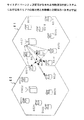
移動機MS1が、例えば、図20に示すように、エリアE1に設置された複数の基地局BS13、BS14、BS15、BS16、BS18と通信を行う状態になると、各基地局は、エリアE1を管轄する回線制御局RNC1との間でエントランス中継系回線を設定する。そして、各基地局は、移動機MS1から受信した信号を中継してエントランス中継系回線を介して回線制御局RNC1に伝送する。移動機MS1からの信号を複数の基地局BS13、BS14、BS15、BS16、BS18を介して受信した回線制御局RNC1は、それらの信号を合成して基幹回線に送出する。
【0011】
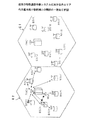
上記の状態から移動機MS1が移動して、例えば、図21に示すように、エリアE1におけるエリアE2との境界部分に達すると、移動機MS1は、複数の基地局BS13、BS14、BS15、BS21、BS27と通信を行う状態となる。この場合、エリアE1に設置された各基地局BS13、BS14、BS15は、当該エリアE1を管轄する回線制御局RNC1との間にエントランス中継系回線を設定して移動機MSからの信号を中継し、回線制御局RNC1に伝送する。また、エリアE2に設置された各基地局BS21、BS27は、当該エリアE2を管轄する回線制御局RNC2との間にエントランス中継系回線を設定して移動機MS1からの信号を中継し、回線制御局RNC2に伝送する。そして、移動機MS1からの信号は、各回線回制御局RNC1、RNC2を結ぶ移動通信ネットワークの基幹回線を経由していずれか一方の回線制御局に集約され、サイトダイバーシティ合成される。
【0012】
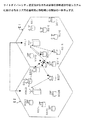
更に移動機MS1が移動して、例えば、図22に示すように、エリアE1を超えてエリアE2におけるエリアE1との境界部分に達すると、移動機MS1は、複数の基地局BS13、BS14、BS21、BS22、BS27と通信を行う状態となる。この場合も、エリアE1に設置された各基地局BS13、BS14は、当該エリアE1を管轄する回線制御局RNC1との間にエントランス中継系回線を設定する一方、エリアE2に設置された各基地局BS21、BS22、BS27は、当該エリアE2を管轄する回線制御局RNC2との間にエントランス中継系回線を設定する。エリアE1内の各基地局BS13、BS14にて中継された移動機MS1からの信号は、回線制御局RNC1に伝送され、エリアE2内の各基地局BS21、BS22、BS27にて中継された移動機MS1からの信号は、回線制御局RNC2に伝送される。そして、上記の同様に、各回線制御局RNC1、RNC2にて受信された各基地局からの信号が移動通信ネットワークの基幹回線を経由していずれか一方の回線制御局に集約され、サイトダイバーシティ合成される。
【0013】
更に移動機MS1が移動して、例えば、図23に示すように、エリアE 2の中央部に達すると、複数の基地局BS23、BS24、BS25、BS26、BS27と通信を行う状態となる。この場合は、各基地局BS23、BS24、BS25、BS26、BS27は、エリアE2を管轄する回線制御局RNC2との間にエントランス中継系回線を設定し、移動機MS1からの信号を中継して当該回線制御局RNC2に伝送する。そして、このようにエリアE2内の各基地局によって中継されて回線制御局RNC2に伝送された信号が、当該回線制御局RNC2によって基幹回線に送出される。
【0014】
【発明が解決しようとする課題】
上述したように、移動機MS1が隣接するエリアE1、E2の境界を通過する際に(図17及び図18参照)、電波の状況、建造物の配置などによって、移動機MS1は、エリアE1に設置された基地局と通信を行ったり(図18)、エリアE2に設置された基地局と通信を行ったりするように(図17)、隣接エリアE1、E2のそれぞれに分かれた基地局間でのハンドオーバーが頻繁に行われる場合がある。特に、各エリアが多数のマイクロセルで構成される都市部においては、移動機MS1が他のエリアと隣接するエリアの境界部分を移動している際に、移動機MS1からの電波が隣接する他のエリアの基地局に容易に到達し、当該移動機MS1からの信号が隣接する他のエリア内の基地局にて中継される頻度が高くなる。
【0015】
このような場合、従来の移動通信中継システムでは、各基地局はそれらが設置されたエリアを管轄する回線制御局RNCとの間にエントランス中継系回線を設定すべきことが固定的に定められているので、移動機MS1が隣接するエリアの境界線を通過する際に、回線制御局RNC間でのハンドオーバーが頻繁に行われることになる。その結果、回線制御局RNC間における基幹回線設定のための負荷が増大し、また、回線制御局間における基幹回線の通信量が増大して、円滑な中継動作が損なわれることがある。
【0016】
更に、移動機MS1と通信を行う基地局が固定的に定められた回線制御局にエントランス中継系回線の設定の要求を行った際に、当該回線制御局において設定すべきエントランス中継系回線に余裕がないと、当該基地局と回線制御局との間にエントランス中継系伝送回線を設定することができない。その結果、移動機MS1への通信サービスを行うことができなくなってしまう。
【0017】
また、更に、基地局と回線制御局との間に無線によるエントランス中継系回線を設定するシステムでは、電波の降雨減衰など、基地局と固定的に定められた回線制御局との間の電波の送受信状態が悪い場合、基地局と回線制御局との間にエントランス中継系回線を設定することができないことがある。このような場合も、移動機MS1に対して通信サービスを提供する手立てがない。
【0018】
また、従来の移動通信中継システムにおいて、前述したようなサイトダイバーシティ送受信を行う場合、移動機MS1が隣接するエリアE1、E2の境界部を移動する際に、当該移動機MS1からの信号が双方のエリアE1、E2に設置された基地局を介して双方のエリアを管轄する回線制御局RNC1、RNC2にて伝送される状況になり得る(図21、図22参照)。このような場合、各回線制御局RNC1、RNC2で受信した信号を合成するために、各回線制御局RNC11、RNC2間で基幹回線を介して通信を行って、移動機MS1からの信号をいずれか一方の回線制御局に集約する必要がある。このため、その信号集約のための動作や、各回線制御局RNC1、RNC2間の基幹回線のトラフィックが増大してしまうことににより、円滑な中継動作が損なわれることがある。
【0019】
そこで、本発明の第一の課題は、移動機の送受信信号の中継をできるだけ円滑に行えるような移動通信中継システムを提供することである。
また、本発明の第二の課題は、そのような移動通信中継システムにおいて用いられる基地局を提供することである。
【0020】
【課題を解決するための手段】
上記第一の課題を解決するため、本発明は、請求項1に記載されるように、移動機に対して通信サービスを提供するための複数の基地局と、複数の制御局とを有し、移動機と通信を行う基地局と制御局との間に中継系伝送回線を設定し、該制御局を介して上記移動機と通信を行う基地局を所定の網に接続するようにした移動通信中継システムにおいて、移動機と通信を行う基地局を接続すべき制御局を、上記移動局が各制御局により管理されるエリアの境界線を通過する場合に、切り替えるように決定する制御局決定手段と、該制御局決定手段にて決定された制御局との間に中継系伝送回線が設定されるように回線切替え制御を行う回線制御手段とを有するように構成される。
【0021】
このような移動通信中継システムでは、移動機と通信を行う基地局を接続すべき制御局は、固定的に定められいるのではなく、所定の条件に基づいて決定される。そして、その移動機と通信を行う基地局と上記条件に基づいて決定された制御局との間に中継系伝送回線が設定されるように回線切替え制御がなされる。
所定の条件に基づいて移動機と通信を行う基地局を接続すべき制御局が決定されるので、その所定の条件に応じた態様での中継動作が可能となる。
【0022】
この所定の条件は、移動機の送受信信号を円滑に中継できるという観点から任意に定めることができる。例えば、移動機の地理的な位置に関する条件、中継回線が設定できない場合における優先順位の条件、中継系伝送回線が無線回線の場合においてその通信品質に関する条件などの条件に基づいて移動機と通信を行う基地局と接続すべき制御局を決定することができる。
【0023】
基地局と制御局との位置関係に関わりなく、移動機の地理的な位置に応じて、当該移動機と通信を行う基地局と適切な制御局との間に中継系伝送回線が設定できるという観点から、本発明は、請求項2に記載されるように、上記移動通信中継システムにおいて、上記制御局決定手段は、移動機の存在する地理的位置を表す位置情報に基づいて当該移動機と通信を行う基地局を接続すべき制御局を決定するように構成することができる。
【0024】
上記移動機の地理的位置は、移動機にて計測しても、基地局側で測定することも可能である。また、移動機の地理的位置の測定方法として既知の測定方法、例えば、基地局などの複数の通信設備と移動機との間で通信を行って移動機の位置を特定するネットワーク測位技術、所謂高度道路交通システムにおける管制センタからの情報を用いる方法、GPSを利用する方法、路面に埋設したマーカからの信号を用いる方法などを利用することができる。
【0025】
また、各制御局が管轄するエリアが定められている場合において、隣接するエリアを移動機が通過しようとする際に、移動機と通信する基地局の切替えに応じて中継する制御局が頻繁に切り替えられるという状態を防止するという観点から、本発明は、請求項3に記載されるように、上記移動通信中継システムにおいて、上記各制御局が管轄するエリアが予め定められ、上記制御局決定手段は、移動機の位置情報に基づいて当該移動機が圏在するエリアを判定するエリア判定手段を有し、該エリア判定手段にて判定されたエリアを管轄する制御局を上記移動機と通信を行う基地局を接続すべき制御局として決定するように構成することができる。
【0026】
このような移動通信中継システムでは、移動機と通信を行う基地局の地理的な条件がどのようなものであっても、当該移動機が圏在するエリアを管轄する制御局と当該移動機と通信を行う基地局との間に中継系伝送回線が設定される。従って、移動機が隣接するエリアの一方のエリアに圏在する間は、当該移動機が他方のエリアに設置される基地局と通信を行っていたとしても、当該基地局と当該一方のエリアを管轄する制御局との間に中継系伝送回線が設定される。その結果、移動機が隣接するエリアの境界線を通過しようとする際に、移動機と通信を行う基地局の切替えにより、各基地局と中継系伝送回線にて接続される制御局が頻繁に切替わることが防止される。
【0027】
何らかの原因によって移動機と通信を行う基地局と制御局との間に中継系伝送回線が設定できないときに、当該基地局を他の制御局と接続できるようにするという観点から、本発明は、請求項4に記載されるように、上述した各移動通信中継システムにおいて、上記回線制御手段が上記移動機と通信を行う基地局と上記制御局決定手段にて決定された制御局との間に中継系伝送回線の設定ができなかったときに、上記制御局決定手段は、予め定めた優先順位に従って当該基地局を接続すべき制御局を決定するように構成することができる。
【0028】
このような移動通信システムでは、1つの制御局にて設定可能な中継系伝送回線に余裕がない場合や、移動機と通信を行う基地局とその1つの制御局との間の通信状態が悪い場合など、移動機は、所定の優先順位に基づいて決定された他の制御局を中継して通信サービスを受けることができるようになる。
移動機からの信号をサイトダイバーシティ合成する際に、制御局間の通信をできるだけ低減するという観点から、本発明は、請求項5に記載されるように、上述した各移動通信中継システムにおいて、移動機からの信号をサイトダイバーシティ合成するための複数の基地局を決定する基地局決定手段を有し、該基地局決定手段にて決定された各基地局と上記のように決定された単一の制御局との間に中継系伝送回線が設定された状態で、当該制御局において上記各基地局から中継系伝送回線を介して提供される移動機からの信号を合成するように構成することができる。
【0029】
このような移動通信中継システムでは、移動機からの信号をサイトダイバーシティ合成するための複数の基地局が決定されると、その複数の基地局が接続されるべき単一の制御局が上記所定の条件に基づいて決定される。そして、当該複数の基地局のそれぞれと当該決定された制御局との間に中継系伝送回線が設定される。そして、移動機からの信号が各基地局及び中継系伝送回線を介して制御局に伝送され、当該制御局にて受信した移動機からの複数の信号がサイトダイバーシティ合成される。従って、サイトダイバーシティ合成すべき移動機からの信号が複数の制御局に分かれることが防止され、その結果、制御局間で通信を行う必要性を低減することができる。
【0030】
上記のように移動機からの信号をサイトダイバーシティ合成するようにした移動通信中継システムにおいて、当該サイトダイバーシティ合成がより効果的にできるという観点から本発明は、請求項6に記載されるように、上記移動通信中継システムにおいて、上記基地局決定手段は、移動機と複数の基地局との間の通信品質に基づいて当該移動機からの信号をサイトダイバーシティ合成するための複数の基地局を決定するように構成することができる。
【0031】
このような移動通信中継システムでは、移動機と良好な通信品質にて通信を行う基地局を介して当該移動機からの信号が制御局に伝送されるので、サイトダイバーシティ合成をより効果的に行うことができるようになる。
移動機からの信号おサイトダイバーシティ合成するための複数の基地局を決定するための移動機と各基地局との通信品質は、移動機または基地局での受信信号にて判断することができる。この通信品質として、当該受信信号の強度、当該受信信号に対する他の信号の干渉状況、当該受信信号の誤り訂正率などを用いることができる。
【0032】
移動機からの信号をサイトダイバーシティ合成するための複数の基地局を容易に判定できるという観点から、本発明は、請求項7に記載されるように、上記移動通信中継システムにおいて、上記基地局決定手段は、上記制御局に設けられるように構成することができる。
このような移動通信中継システムでは、制御局は複数の基地局からの情報を収集することができるので、その収集した情報に基づいてサイトダイバーシティ合成を行うための複数の基地局を容易に決定することができる。
【0033】
基地局を接続すべき制御局を効率的に決定できるという観点から、本発明は、請求項8に記載されるように、上記移動通信中継システムにおいて、上記制御局決定手段は、各基地局に設けられ、移動機と通信を行う基地局における制御局決定手段が当該基地局を接続すべき制御局を決定するように構成することができる。
【0034】
このような移動通信中継システムでは、基地局は、移動機と制御局の双方と通信を行うことが可能であるので、移動機に関する条件、あるいは、制御局に関する条件のいずれに基づいても効率的に接続すべき制御局を決定することができる。
また、基地局において決定された制御局に対して中継系伝送回線を設定するたための具体的な構成を提供するという観点から、本発明は、請求項9に記載されるように、上記移動通信中継システムにおいて、上記回線制御手段は、各基地局に設けられ、複数の制御局と中継系伝送回線を設定するための複数のエントランス回線送受信機と、上記制御局決定手段にて決定された制御局との間に中継系伝送回線を設定するように上記複数のエントランス回線送受信機の選択切替えを行う切替え装置とを有するように構成することができる。
【0035】
中継伝送回線の設定が柔軟に行えるという観点から、本発明は、請求項10に記載されるように、上記各移動通信中継システムにおいて、基地局と制御局との間で設定されるべき上記中継系伝送回線は無線回線であって、各基地局は、複数の制御局と個々的な通信を可能とするフェーズドアレーアンテナを備え、該フェーズドアレイアンテナを介して上記制御局決定手段にて決定された制御局との間に中継系伝送回線が設定されるように構成することができる。
【0036】
このような移動通信中継システムでは、フェーズアレーアンテナの制御によって基地局に対して種々の方向に設置された制御局との間に無線回線となる中継系伝送回線を設定できるようになる。
また、同様の観点から、本発明は、請求項11に記載されるように、上記各移動通信中継システムにおいて、上記基地局と制御局との間で設定されるべき上記中継系伝送回線は無線回線であって、各基地局は、複数の制御局の方向を向く複数の指向性アンテナを備え、上記制御局決定手段にて決定された制御局に向く指向性アンテナを介して当該制御局との間に中継系伝送回線が設定されるように構成することができる。
【0037】
このような移動通信中継システムでは、指向性アンテナを選択することによって、基地局に対して種々の方向に設置された制御局との間に無線回線となる中継系伝送回線を設定できるようになる。
前述したように、上記各制御局が管轄するエリアが予め定められた移動通信中継システムにおいて、隣接するエリアの境界線を繰り返し通過する場合であっても、中継系伝送回線の切替えが繰り返し行われないようにするという観点から、本発明は、請求項12に記載されるように、上記移動通信中継システムにおいて、隣接する各エリアにおける隣接部分の所定範囲が緩衝エリアとして設定され、上記回線制御手段は、移動機が当該緩衝エリア内に圏在するときは、上記エリア判定手段にて判定される移動機が圏在するエリアが変更されても、当該移動機と通信を行う基地局と制御局との間に設定された中継系伝送回線の設定状態を維持する回線維持制御手段を有するように構成される。
【0038】
このような移動通信中継システムでは、移動機が隣接するエリアの緩衝エリア内に圏在するときは、エリア判定手段にて判定される移動機が圏在するエリアが変更されても、当該移動機と通信を行う基地局と制御局との間に設定された中継系伝送回線の設定状態が維持されるので、隣接するエリアの境界線を繰り返し通過するように移動機が移動しても、中継系伝送回線の切替えが行われることが防止される。
【0039】
このような移動通信中継システムのより具体的な構成を提供するという観点から、本発明は、請求項13に記載されるように、上記移動通信中継システムにおいて、移動機の位置情報に基づいて当該移動機が隣接するエリアにおける緩衝エリアに圏在するか否かを判定する緩衝エリア内判定手段と、移動機の位置情報の変化に基づいて当該移動機が隣接するエリアの境界線を通過したか否かを判定する境界通過判定手段とを備え、上記回線維持制御手段は、上記境界通過判定手段にて当該移動機が隣接するエリアの境界線を通過したと判定された後に、上記緩衝エリア内判定手段にて当該移動機が緩衝エリアに圏在していると判定されている間は、上記隣接するエリアの境界線を通過する直前において当該移動機と通信を行う基地局と制御局との間に設定された中継系伝送回線の設定状態を維持するように構成することができる。
【0040】
上記境界通過判定手段での判定の基礎となる移動機の位置情報の変化は、移動機の地理的位置の履歴から得ることができる。この履歴は、移動機にて生成することも基地局にて生成することもできる。
隣接するエリアの境界部を一方のエリアから他方のエリアに通過する際、緩衝エリアを脱したときに制御局の切替えが的確に行えるという観点から、本発明は、請求項14に記載されるように、上記境界線通過判定手段にて当該移動機が隣接するエリアの境界線を通過したと判定される毎に、一方のエリアから他方のエリアに移動した第一の状態と当該他方のエリアから当該一方のエリアに戻った第二の状態が交互に設定される状態設定手段を有し、上記回線制御手段は、上記状態設定手段に第一の状態が設定されている状態において、上記緩衝エリア内判定手段にて当該移動機が緩衝エリア内に圏在していない判定されたときに、当該移動機と通信を行う基地局と上記エリア判定手段にて判定されたエリアを管轄する制御局との間に中継系伝送回線が設定されるように回線の切替えを行うように構成することができる。、
このような移動通信中継システムでは、隣接するエリアの境界線を通過して移動機が一方のエリアから他方のエリアに移動したときに状態設定手段には、第一の状態が設定され、また、当該移動機が隣接するエリアの境界線を通過して当該他方のエリアから当該一方のエリアに戻ったときに状態設定手段には、第二の状態が設定さえる。そして、状態設定手段に第二の状態が設定されている場合には、緩衝エリアから移動機が脱したと判断されても、中継系伝送回線の切替えは行われない。
【0041】
一方、状態設定手段に上記第一の状態が設定されている状態において、移動機が緩衝エリアから脱したと判定されると、移動機が一方のエリアから他方のエリアに確実に進入したものとして、移動機と通信を行う基地局とエリア判定手段にて判定されたエリアを管轄する制御局との間に中継系伝送回線が設定されるように、回線の切替えが行われる。
【0042】
更に、上述した第二の課題を解決するため、本発明は、請求項15に記載されるように、移動機に対して通信サービスを提供する複数の基地局と、複数の制御局とを有し、移動機と通信を行う基地局と制御局との間に中継系伝送回線を設定し、該制御局を介して上記移動機と通信を行う基地局を所定の網に接続するようにした移動通信システムに用いられる基地局において、移動機との間にアクセス回線が設定されたときに、中継系伝送回線を設定すべき制御局を、上記前記移動局が各制御局により管理されるエリアの境界線を通過する場合に、切り替えるように決定する制御局決定手段と、該制御局決定手段にて決定された制御局との間に中継伝送回線が設定されるように回線切替え制御を行う回線制御手段とを有するように構成される。
【0043】
【発明の実施の形態】
以下、本発明の実施の形態を図面に基づいて説明する。
本発明の実施の一形態に係る移動通信中継システムの基本構成は、図16に示すものと同様に構成されている。即ち、通信サービスエリアが複数のエリアに分割され、各エリア内にはそのエリアを管轄する回線制御局が設置されると共に、各エリアを更に細分化するマイクロセルを構成する複数の基地局が設置されている。
【0044】
移動機MS、各基地局BS及び隣接するエリアE1、E2に設置された回線制御局RNC1、RNC2の構成は、例えば、図1に示すようになっている。
図1において、移動機MSと通信を行う基地局BSは、複数の回線制御局RNC1及びRNC2との間で、エントランス中継系無線回線を設定できるようになっている。なお、この例では、基地局BSと各回線制御局RNC1、RNC2との間に設定されるエントランス中継系回線は、無線回線であるが、システムとては、これに限定されず、例えば、光ファイバや金属導線ケーブルにて基地局と各回線制御局RNC1、RNC2が接続される構成でもよい。ただし、基地局BSと各回線制御局RNC1、RNC2との間が無線回線で接続される構成は、回線の設定が柔軟に切替えられる点で好ましい。
【0045】
基地局BSは、複数のアクセス回線送受信機101、位置情報識別装置102、切り替え装置103、マルチプレクサ/デマルチプレクサ104、106、エントランス回線送受信機105及び107、及び制御装置110を有している。上記複数のアクセス回線送受信機101は、移動機MSとの間にアクセス回線を設定し、アンテナ101aを介して移動機MSと通信を行う。各アクセス回線送受信機101は、後述する切替え装置103を介して2系統のエントランス中継系に接続されている。各エントランス中継系は、マルチプレクサ/デマルチプレクサ104(106)とエントランス回線送受信機105(107)を有している。一方のエントランス回線送受信機105は、回線制御局RNC1の方向を向いた指向性アンテナ105aを有しており、回線制御局RNC1との間にエントランス中継系伝送回線を設定して、指向性アンテナ105aを介して回線制御局RNC1と通信を行う。他方のエントランス回線送受信機107は、回線制御局RNC2の方向を向いた指向性アンテナ107aを有しており、回線制御局RNC2との間にエントランス中継伝送回線を設定して、指向性アンテナ107aを介して回線制御局RNC2と通信を行う。
【0046】
各マルチプレクサ/デマルチプレクサ104(106)は、切替え装置103を介して提供される各アクセス回線送受信機101からの受信信号を多重化して対応するエントランス回線送受信機105(107)に供給する。また、各マルチプレクサ/デマルチプレクサ104(106)は、対応するエントランス回線受信機105(107)にて受信した回線制御局RNC1(RNC2)からの多重化された信号を分離して切替え装置103を介して対応するアクセス回線送受信機101に供給する。
【0047】
位置情報識別装置102は、移動機MSから送信される当該移動機MSの地理的な位置に基づいた情報をアクセス回線送受信装置101を介して取得し、移動機MSの位置情報(経度、緯度情報など)を生成する。移動機MSの地理的な位置は、例えば、GPS(Global Positioning System )を利用して移動機MSにおいて測定される。なお、移動機MSの地理的な位置は、基地局を含む複数の受信地点での移動機からの信号の到達時間、到達時間差、到来方向などから所謂うネットワーク測位技術を用いて計測することも、その他既知の方法に従って計測することもできる。
【0048】
制御装置110は、位置情報識別装置102からの移動機MSの位置情報に基づいて切替え装置103を制御する。切替え装置103は、制御装置110での制御のもとに、2系統のエントランス中継系のいずれかの選択切替えを行う。具体的には、移動機MSの位置情報に基づいて当該移動機MSが回線制御局RNC1の管轄するエリアE1に圏在すると判断された場合には、マルチプレクサ/デマルチプレクサ104及びエントランス回線送受信機105を有する第一のエントランス中継系が選択されるように、切替え制御がなされ、一方、当該移動機が回線制御局RNC2が管轄するエリアE2に圏在すると判断された場合には、マルチプレクサ/デマルチプレクサ106及びエントランス回線送受信機107を有する第二のエントランス中継系が選択されるように切替え制御がなされる。
【0049】
また、上記制御装置110は、上記切替え装置103の制御のほか、上記第一及び第二のエントランス中継系にて回線制御局RNC1、RNC2との間にエントランス中継系伝送回線を設定するための各種処理を実行する。その処理については後述する。
隣接するエリアE1、E2に設置された各回線制御局RNC1及びRNC2は、移動通信ネットワーク基幹回線200に接続されている。各回線制御局RNC1、RNC2は、この移動通信ネットワーク基幹回線200を介して相互に通信を行うことが可能となるとともに、他の通信装置との通信も可能となる。
【0050】
この移動通信中継システムの全体的な構成は、前述したように、図16に示した場合と同様であり、例えば、図3に示すようになっている。即ち、隣接するエリアE1、E2のそれぞれに各エリアを管轄する回線制御局RNC1、RNC2が設置され、エリアE1には、マイクロセルを形成する複数の基地局BS11〜BS18が設置されると共に、エリアE2には、マイクロセルを形成する複数の基地局BS21〜BS27が設置されている。
【0051】
このような移動通信中継システムにおいて、例えば、移動機MS1がエリアE1からエリアE2に移動する過程で、当該移動機MS1は、各基地局から止まり木チャネルにて一斉に報知される信号の受信レベルなどに基づいて通信を確立すべき基地局を選択する。そして、移動機MS1との通信が確立してアクセス回線が設定された基地局BS、例えば、図3に示す基地局BS16の制御装置110は、図2に示す手順に従って処理を実行する。
【0052】
図2において、移動機MS1との通信が確立すると、移動機MS1から送信される当該移動機MS1の位置情報が取得され(S1)、この移動機MS1の位置情報に基づいてエントランス中継系伝送回線を設定すべき回線制御局を選択するためのRNC第一選択処理が実行される(S2)。制御装置110は、各回線制御局にて管轄されるエリアの地理的な情報を予め保存したデータベースを有しており、このRNC第一選択処理では、このデータベースの情報と当該移動機MS1の位置情報とを比較して、当該移動機MS1の圏在するエリアを判定し、その判定されたエリアを管轄する回線制御局を当該基地局BS16と接続すべき回線制御局として決定する。この場合、移動機MS1はエリアE1に圏在するので、当該エリアE1を管轄する回線制御局RNC1が基地局BS16を接続すべき回線制御局として決定される。
【0053】
このように移動機MS1との通信が確立された基地局BS16を接続すべき回線制御局RNC1が決定されると、当該基地局BS16からその回線制御局RNC1に対してエントランス中継系伝送回線の設定要求が送信される(S3)。その後、当該基地局BS16の制御装置110は、所定時間To の設定されたタイマを起動し、そのタイマが所定時間To に達するか否かの判定を行いながら(S4)、設定要求の送信先の回線制御局RNC1からの応答の待ち状態になる(S5)。
【0054】
基地局BS16から上記のようなエントランス中継系伝送回線の設定要求を受信した回線制御局RNC1は、自局のエントランス中継系伝送回線に余裕があるときには、基地局BS16に対してエントランス中継系伝送回線の設定の許可情報を返送する。
このようなエントランス中継系伝送回線の設定の許可情報を基地局BS16が受信すると(S5においてYES、S6において「 許可」 )、基地局BS16の制御装置110は、第一のエントランス中継系(マルチプレクサ/デマルチプレクサ104及びエントランス回線送受信機105)が選択されるように、切替え装置103を制御する。その結果、基地局BS16と回線制御局RNC1との間にエントランス中継系伝送回線が設定される(S7)。このように基地局BS16と回線制御局RNC1との間にエントランス中継系伝送回線が設定されると、基地局BS16は、移動機MS1の送受信信号の中継動作を行う(S8)。その結果、移動機MS1からの信号が基地局BS16、回線制御局RNC1を介して移動通信ネットワーク基幹回線200に伝送される一方、移動通信ネットワーク基幹回線200から移動機MS1宛ての信号が、回線制御局RNC1、基地局BS16を介して移動機MS1に伝送される。
【0055】
基地局BS16の制御装置110は、以後、移動機MS1がハンドオフしたか否かの判定(S9)、移動機MS1の位置情報の取得(S10)、移動機MS1の圏在するエリアが変更されたか否かの判定(S11)を行いながら上述した中継動作を実行する。
移動機MS1が移動して、例えば、図4に示すように、エリアE1におけるエリアE2との隣接部分に達するまでの間に、基地局BS16では、移動機MS1のハンドオフが判定され(S9においてYES)、上述した中継動作が終了され、上記処理が終了される。
【0056】
移動機MS1が、まだエリアE1に圏在する状態で、エリアE2に設置された基地局BS21との間にアクセス回線を設定すると、基地局BS21の制御装置110も、上記と同様の手順(図2におけるS1〜S11)に従って処理を実行する。
この場合、RNC第一選択処理(S2)においては、当該基地局BS21はエリアE2に設置されるものの、移動機MS1は、エリアE1にまだ圏在するので、当該エリアE1を管轄する回線制御局RNC1が基地局BS21に接続すべき回線制御局として決定される。その結果、基地局BS21及び回線制御局RNC1の中継動作により、移動機MS1からの信号が基地局BS21、回線制御局RNC1を介して移動通信ネットワーク基幹回線200に伝送される一方、移動通信ネットワーク基幹回線200から移動機MS1宛ての信号が回線制御局RNC1、基地局BS21を介して移動機MS1に伝送される。
【0057】
移動機MS1が更に移動して、例えば、図5に示すように、エリアE2に進入して当該エリアE2におけるエリアE1との隣接部分に達するまでの間に、基地局BS21では、移動機MS1のハンドオフが判定され(S9においてYES)、上述した中継動作が終了され、上記処理が終了される。
移動機MS1が、このようにエリアE2に進入した状態で、エリアE1に設置された基地局BS14との間にアクセス回線を設定すると、基地局BS14の制御装置110も、上記と同様の手順(図2におけるS1〜S11)に従って処理を実行する。
【0058】
この場合、RNC第一選択処理(S2)においては、基地局BS14は、回線制御局RNC1が管轄するエリアE2に圏在するものの、移動機MS1は、エリアE2に既に進入しているので、当該エリアE2を管轄する回線制御局RNC2が基地局BS14に接続すべき回線制御局として決定される。その結果、制御装置110は、エントランス中継系を第一のエントランス中継系から第二のエントランス中継系(マルチプレクサ/デマルチプレクサ106及びエントランス回線送受信機107)に切替えられるように切替え装置103を制御する。そして、基地局BS14及び回線制御局RNC2の中継動作により、移動機MS1からの信号が基地局BS14、回線制御局RNC2を介して移動通信ネットワーク基幹回線200に伝送される一方、移動通信ネットワーク基幹回線200から移動機MS1宛ての信号が回線制御局RNC2、基地局BS14を介して移動機MS1に伝送される。
【0059】
更に、移動機MS1が移動して、例えば、図6に示すように、エリアE2の中央部に至るまでの間に、基地局BS14では、移動機MS21のハンドオフが判定され(S9においてYES)、上述した中継動作が終了され、上記処理が終了される。
移動機MS1が、このようにエリアE2の中央部に圏在する状態おいて、当該エリアE2に設置された基地局BS24との間にアクセス回線を設定すると、基地局BS24の制御装置110も、上記と同様の手順(図2におけるS1〜S11)に従って処理を実行する。
【0060】
この場合、RNC第一選択処理(S2)においては、基地局BS24は、移動機MS1が、エリアE2に圏在するので、当該エリアE2を管轄する回線制御局RNC2が基地局BS24に接続すべき回線制御局として決定される。その結果、基地局BS24及び回線制御局RNC2の中継動作により、移動機MS1からの信号が基地局BS24、回線制御局RNC2を介して移動通信ネットワーク基幹回線200に伝送される一方、移動通信ネットワーク基幹回線200から移動機MS1宛ての信号が回線制御局RNC2、基地局BS24を介して移動機MS1に伝送される。
【0061】
上記のように移動機MS1とアクセス回線を設定して当該移動機MS1と通信が確立した各基地局BSでの処理により、各基地局BSは、常に、移動機MS1が圏在するエリアを管轄する回線制御局に接続されるように、エントランス中継系伝送回線が設定される。従って、移動機MS1が隣接するエリアE1、E2の境界線を一方のエリアE1から他方のエリアE2に移動する際に(図3乃至図6参照)、移動機MS1と基地局間の電波の状態や、建造物等の影響によって、移動機MS1が、エリアE1内の基地局と通信を確立する状況と、エリアE2内の基地局と通信を確立する状況が繰り返されたとしても(図4及び図5参照)、エントランス中継系伝送回線によって各基地局に接続される回線制御局は、当該移動機MS1が隣接するエリアE1とE2の境界線を通過するときにのみ、回線制御局RNC1からRNC2に切替えられるだけである。その結果、各回線制御局RNC1、RNC2間でのハンドオーバの頻度が低減し、各回線制御局RNC1、RNC2間における基幹回線設定のための負荷が増大することを防止できると共に、各回線制御局RNC1、RNC2における基幹回線の通信量の増大も防止することができる。
【0062】
移動機MS1と通信が確立した基地局での図2に示す手順に従った処理において、例えば、当該基地局BSから上記のようにして決定された回線制御局RNCに対するエントランス中継系伝送回線の設定要求(図2におけるS3)が、降雨減衰などにより正常に回線制御局にて受信されない場合、当該基地局BSでは、タイマTが所定時間To に達しても、回線制御局から応答信号が受信されない(S4においてYES)。また、エントランス中継系伝送回線の設定要求を受信した回線制御局RNCがエントランス中継系伝送回線の余裕がない場合には、当該回線制御局RNCは、設定不可の応答を要求元の基地局BSに返送する(図2におけるS6において「 不可」 )。これらの場合には、更に、RNC第二選択処理が実行さされる(S13)。
【0063】
制御装置110は、当該基地局が接続されるべき回線制御局が所定の優先順位に従って予め記憶されている。そして、上記RNC第二選択処理(S13)では、接続要求が拒否された回線制御局以外の回線制御局で最も優先順位の高いものが、当該基地局が接続されるべき回線制御局として決定される。
その後、上述した処理と同様に、その決定された回線制御局に対してエントランス中継系伝送回線の設定要求が送信され(S14)、その要求先の回線制御局から許可情報を所定時間To 内に受信すると(S15、S16)、その回線制御局との間にエントランス中継系伝送回線が設定されるように、エントランス中継系が切替えられる(S7)。以後、同様にして、当該基地局及びエントランス中継系伝送回線が設定された回線制御局での中継動作等が行われる(S8、S9、S10、S11)。
【0064】
なお、所定時間に設定要求を行った後の所定時間内に回線制御局からの応答がない場合、また、回線制御局からのエントランス中継系伝送回線の設定不可の情報を受信した場合には、エントランス中継系伝送回線が設定できないものとして、処理が終了する(S15、S16、S17、S18)。
上述したような処理により、各基地局は、移動機MS1の位置情報に基づいて決定された回線制御局との間にエントランス中継系伝送回線が設定できない場合であっても、所定の優先順位にて定められた他の回線制御局との間にエントランス中継系伝送回線を設定できるようになる。このため、より円滑な中継動作が可能となる。
【0065】
移動機MS1との間にアクセス回線が設定され当該移動機MS1と通信を行う基地局BSは、前述したように、移動機MS1が圏在するエリアを管轄する回線制御局または、優先順位に従って決定された回線制御局との間にエントランス中継系伝送回線を設定した後に、ハンドオフの判定(S9)、移動機MS1からの位置情報の取得(S10)、移動機MS1の圏在するエリアの変更判定(S11)を行いながら中継動作を実行している(S8)。この過程で、移動機MS1の圏在するエリアが変更したことが判定されると(S11においてYES)、更に、その変更後のエリアを管轄する回線制御局との間にエントランス中継系伝送回線が既に設定されているか否かが判定される(S12)。ここで、当該基地局BSと変更後のエリアを管轄する回線制御局との間にエントランス中継伝送回線が既に設定されている場合には(S12においてYES)、当該基地局BSは、そのエントランス中継伝送回線の設定状態を維持して中継動作を継続する(S8)。
【0066】
一方、当該BSと変更後のエリアを管轄する回線制御局との間にまだエントランス中継系伝送回線が設定されていない場合には(S12においてNO)、現在取得している移動機MS1の位置情報に基づいて前述したRNC第一選択処理(S2)が実行される。その結果、当該基地局は、変更後のエリアを管轄する回線制御局に対してエントランス中継系伝送回線の設定要求を送信し(S3)、該回線制御局から設定許可の応答信号が受信されると(S4、S5、S6)、前述した場合と同様に、エントランス中継系が当該回線制御局に対応するものに切替えられ、当該基地局とその変更後のエリアを管轄する回線制御局との間にエントランス中継系伝送回線が設定される。そして、当該基地局は中継動作を行う(S8)。以後、前述した場合と同様の処理が行われる。
【0067】
次に、移動機MSが複数の基地局と通信を行うことにより、サイトダイバーシティ送受信を行う場合の例について説明する
各エリアE1、E2を管轄する各回線制御局RNC1、RNC2には、サイトダイバーシティ送受信を行う基地局の局数の最大値(例えば、5局)が予め定められている。
【0068】
例えば、図7に示すように移動機MS1は、周囲の基地局BS13、BS14、BS15、BS16、BS18と通信を行う。そして、移動機MS1は、各基地局BS13、BS14、BS15、BS16、BS18から受信される信号の受信品質(例えば、受信レベル、他の移動局からの干渉信号強度、誤り訂正率など)を測定し、その測定結果を受信状況情報として、当該移動機MS1の位置情報と共に各基地局BS13、BS14、BS15、BS16、BS18に対して送信する。このように移動機MS1と通信を行う各基地局BS13、BS14、BS15、BS16、BS18は、図2に示す処理と同様の処理を実行する。
【0069】
即ち、移動機MS1からの位置情報に基づいて当該移動機MS1が圏在するエリアE1を管轄する回線制御局RNC1が決定され(S2)、その決定された回線制御局RNC1に対してエントランス中継系伝送回線の設定要求が送信される(S3)。この際、移動機MS1から受信された受信状況情報もその決定された回線制御局RNC1に送信される。
【0070】
このように複数の基地局BS13、BS14、BS15、BS16、BS18からエントランス中継系伝送回線の設定要求及び受信状況情報を受信した回線制御局RNC1は、それらの受信状況情報に基づいて、サイトダイバーシティ送受信を行うための基地局を決定する。例えば、該受信状況情報で表される信号の受信品質が所定レベル以上とななる5局(最大値)以下の基地局がサイトダイバーシティ送受信を行うための基地局として決定される。この場合、各基地局BS13、BS14、BS15、BS16、BS18がサイトダイバーシティ送受信を行う基地局として決定されたとする。
【0071】
また、この回線制御局RNC1は、すでに設定された伝送回線の状況から輻輳などの問題がないと判断すると、各基地局BS13、BS14、BS15、BS16、BS18に対して許可情報を返送する。各基地局BS13、BS14、BS15、BS16、BS18は、この許可情報を受信すると(図2のS6において「 許可」 )、回線制御局RNC1との間にエントランス中継系伝送回線が設定されるように、切替え装置103がエントランス中継系の切替えを行う(S7)。
【0072】
この状態で、移動機MS1と通信を行う複数の基地局BS13、BS14、BS15、BS16、BS18は、移動機MS1からの信号を中継して回線制御局RNC1に送信する(S8)。そして、回線制御局RNC1は、これらの基地局BS13、BS14、BS15、BS16、BS18からの信号を合成して移動通信ネットワーク基幹回線200に送出する。また、回線制御局RNC1は、移動通信ネットワーク基幹回線200から移動機MS1宛ての信号を受信すると、その信号をエントランス中継系伝送回線で接続された各基地局BS13、BS14、BS15、BS16、BS18に送信する。そして、それら各基地局は、回線制御局RNC1からの信号を中継して移動機MS1に送信する。
【0073】
このようにして、複数の基地局BS13、BS14、BS15、BS16、BS18によって、サイトダイバーシティ送受信が行われる。
移動機MS1が移動して、例えば、図8に示すように、エリアE1のエリアE2との隣接部分に達するまでの間に、基地局BS16、BS18では、移動機MS1のハンドオフが判定され(S9)、上述した中継動作が終了される。
【0074】
移動機MS1が図8に示すようにエリアE1に圏在する状態となる場合、この移動機MS1との間のアクセス回線を維持するエリアE1内の基地局BS13、BS14、BS15は、回線制御局RNC1との間に設定されたエントランス中継系伝送回線の設定状態を維持する(S8〜S11)。また、新たにアクセス回線を設定して通信を開始したエリアE2内の基地局BS21、BS27は、移動機MS1からの位置情報に基づいてエリアE1を管轄する回線制御局RNC1が接続されるべき回線制御局であると判断し、この回線制御局RNC1に対してエントランス中継系伝送回線の設定要求を、移動機MS1との通信における受信品質を表す受信状況情報と共に送信する(S1、S2、S3)。
【0075】
回線制御局RNC1は、新たに設定要求のあった基地局BS21、BS27からの受信状況情報、中継系伝送回線の設定状況に基づいてサイトダイバーシティ送受信に適した条件を満たしていると判断すると、更に、基地局BS21、BS27に対して、エントランス中継系伝送回線の設定許可情報を送信する。
この設定許可情報を受信した基地局BS21、BS27は、回線制御局RNC1との間にエントランス中継系伝送回線を設定する。その結果、エリアE1内の基地局BS13、BS14、BS15及びエリアE2内の基地局BS21、BS27がエリアE1を管轄する回線制御局RNC1にエントランス中継系伝送回線にて接続され、それら5局の基地局によって移動機MS1に対するサイトダイバーシティ送受信が行われる。
【0076】
移動機MS1が更に移動して、例えば、図9に示すように、エリアE2に進入して当該エリアE2におけるエリアE1との隣接部分に達するまでの間に、基地局BS15では、移動機MS1のハンドオフが判定され(S9においてYES)、上述した中継動作が終了される。
移動機MS1がエリアE1からエリアE2に進入すると、回線制御局RNC1との間にエントランス中継系伝送回線を設定して中継動作を行っていた各基地局BS13、BS14、BS21、BS27は、移動機MS1の圏在するエリアがエリアE1からエリアE2に変更されたことを判別する(S11においてYES)。すると、各基地局BS13、BS14、BS21、BS27は、移動機MS1の位置情報に基づいて接続されるべき回線制御局がエリアE2を管轄する回線制御局RNC1であると判定する(S2)。
【0077】
また、移動機MS1がエリアE2に進入して、当該移動機MS1との間にアクセス回線を設定して新たに通信を開始した基地局BS22も、当該移動機MS1の位置情報に基づいて接続されるべき回線制御局としてエリアE2を管轄する回線制御局RNC2を決定する(S2)。
以後、前述した手順と同様に、移動機MS1と通信を行う各基地局BS13、BS14、BS21、BS27、BS22は、エリアE2を管轄する回線制御局RNC2に対してエントランス中継系伝送回線の設定要求を送信する(S3)。そして、回線制御局RNC2は、上記と同様に、サイトダイバーシティ送受信を行うための条件が満足されていると判定すると、上記要求のあった各基地局BS13、BS14、BS21、BS27、BS22に対して許可情報を送信する。
【0078】
回線制御局RNC2から許可情報を受信した(S6においてYES)各移動機BS13、BS14、BS21、BS27は、回線制御局RNC1に対応したエントランス中継系を回線制御局RNC2に対応したエントランス中継系に切替え、当該回線制御局RNC2との間にエントランス中継系伝送回線を設定する(S7)。また、上記許可情報を受信した基地局BS21は、回線制御局RNC2と新たに接続されるように、当該回線制御局RNC2との間にエントランス中継系伝送回線を設定する(S7)。
【0079】
このように、5局の基地局BS13、BS14、BS21、BS27、BS21がエントランス中継系伝送回線にて回線制御局RNC2に接続された状態で、上述したのと同様に、移動機MS1に対するサイトダイバーシティ送受信が行われる。
更に、移動機MS1が移動して、例えば、図10に示すように、エリアE2の中央部に至るまでの間に、各基地局BS13、BS14、BS21、BS22では、移動機MS21のハンドオフが判定され(S9においてYES)、上述したような中継動作が終了される。
【0080】
移動機MS1がこのようにエリアESの中央部に圏在する状態において、移動機MS1と通信を行っている基地局BS27は、回線制御局RNC2との間に設定されたエントランス中継系伝送回線の設定状態を維持する(S8〜S11)。また、移動機MS1との間にアクセス回線を設定して当該移動機MS1と通信を開始した各基地局BS23、BS24、BS25、BS26は、上述した手順と同様の手順にて、移動機MS1の位置情報に基づいてエリアE 2を管轄する回線制御局RNC2に対してエントランス中継系伝送回線の設定要求を送信する(S2)。
【0081】
これら各基地局からエントランス中継系伝送回線の設定要求を受信した回線制御局RNC2は、上記と同様に、サイトダイバーシティ送受信を行うための条件が満足されていることが判定されると、各基地局に対して許可情報を送信する。この許可情報を受信した各基地局BS23、BS24、BS25、BS26は、回線制御局RNC2との間にエントランス中継系伝送回線が設定されるように、エントランス中継系の選択切替えを行う(S7)。その結果、回線制御局RNC2との間にエントランス中継伝送回線が設定された5局の基地局BS27、BS23、BS24、BS25、BS25によって移動機MS1に対するサイトダイバーシティ送受信が行われる。
【0082】
移動機MS1に対して複数の基地局によってサイトダイバーシティ送受信を行うようにした上記例では、移動機MS1が隣接するエリアE1、E2の境界部を移動する際に(図8、図9参照)、移動機MS1と通信を行う複数の基地局BSが隣接するエリアE1、E2に分散されていても、全ての基地局BSが当該移動機MS1の圏在するエリアを管轄する回線制御局とエントランス中継系伝送回線によって接続される。従って、各エリアE1、E2に分散された各基地局BSからの信号が双方のエリアE1、E2を管轄する回線制御局RNC1、RNC2に伝送されることがなく、サイトダイバーシティ合成を行うために、一方の回線制御局にて受信した信号を基幹回線を介して他方の回線制御局へ集約させる必要がなくなる。そのため、各回線制御局での負荷の増大及び基幹回線200における通信量の増加を防止することができる。その結果、サイトダイバーシティ送受信を利用した円滑な中継動作を行うことができる。
【0083】
ところで、上記のように移動機MSの位置情報に基づいて当該移動機MSと通信を行う基地局をエントランス中継系伝送回線にて接続すべき回線制御局を決めるようにした移動通信中継システムでは、当該移動機MSが相互に隣接するエリアの当該隣接部分を移動する際に、位置情報の測定誤差などに起因して、移動機MSと通信を行う基地局において頻繁にエントランス中継系伝送回線の切替えが発生する場合がある。次に説明する例は、移動機MSが隣接するエリアの当該隣接部分を移動する際に、中継動作を行う基地局においてエントランス中継系伝送回線の頻繁な切替えが発生することを確実に防止したものである。
【0084】
図12に示すように、各回線制御局RNC1、RNC2が管轄するエリアE1、E2の外周部分に緩衝エリアE1a、E2aが設定されている。そして、移動機MS1と通信を行う基地局は、図2に示す手順におけるステップS11を、図11に示すステップS110に変更した処理を実行する。
例えば、図12に示すように、移動機MS1がエリアE1の緩衝エリアE1より内側に圏在する場合、当該移動機MS1と通信を行う基地局BS16は、前述したのと同様の手順に従って、エリアE1を管轄する回線制御局RNC1との間にエントランス中継系伝送回線を設定し、図11に示す手順に従って中継動作を行う。即ち、移動機MS1のハンドオフを確認(S9)、移動機MS1の位置情報Piの取得(S10)、移動機MS1の圏在するエリアが変更されたか否かの判定(S110)を行いつつ、中継動作を行う(S8)。
【0085】
上記移動機MS1の圏在するエリアが変更されたか否かの判定(S110)は、次のような手順で行われる(図11参照)。
状態フラグFがセットされているか(F=1)否かが判定される(S111)。なお初期においては、状態フラグFは「0」にリセットされている。この場合、まだ状態フラグFがセットされていないので、更に、移動機MS1の位置情報の変化(Pi−1→Pi:位置情報履歴)に基づいて当該移動機MS1がエリアE1とエリアE2の境界線を通過したか否かが判定される(S113)。図12の場合、移動機MS1は隣接するエリアE1、E2の境界線をまだ通過していないので、そのまま中継動作の処理に戻る(S8)。基地局BS16は、移動機MS1と通信を行って中継動作を行っている間、上述した状態フラグFの判定(S111)、移動機MS1の境界線通過の判定(S113)が行われる。
【0086】
移動機MS1が移動してエリアE1の緩衝エリアE1a に達した状態で、エリアE2に設置された基地局BS21と通信を開始すると(図13に示す状態に至る直前の状態)、前述したように、基地局BS21は、移動機MS1の位置情報に基づいて、移動機MS21が圏在するエリアE1を管轄する回線制御局RNC1との間にエントランス中継系伝送回線を設定し、中継動作を行う。
【0087】
この状態では、移動機MS1がまだエリアE1とエリアE2の境界線を通過していないので、上述した基地局BS16での処理と同様に、基地局BS21は、状態フラグFの判定(S111)、移動機MSが境界線を通過したか否かの判定(S113)を行いつつ中継動作を行う。そして、移動機MS1が図13に示すように、エリアE1とエリアE2の境界線を越えると、基地局BS21は、移動機MS1の位置情報の変化(Pi−1→Pi:位置情報履歴)に基づいて移動機MS1がエリアE1、E2の境界線を通過したことを判定する(S113においてYES)。このように移動機MS1がエリアE1、E2の境界線を通過したことが判定されると、上記状態フラグFが反転される(S114)。即ち、状態フラグFが「1」にセットされる(F=1)。この状態で、基地局BS21は、状態フラグFの判定(S111)、移動機MS1の位置情報に基づいて移動機MS1が緩衝エリア外に圏在するか否かの判定(S112)、移動機MS1がエリアE1、E2の境界線を通過したかの判定(S113)を行いながら、中継動作を行う(S8)。このような処理により、移動機MS1はエリアE1からエリアE2に進入したにもかかわらず、移動機MS1がまだエリアE2の緩衝エリアE2aに圏在することから、エリアE1を管轄する回線制御局RCN1との間にエントランス中継系伝送回線を設定した状態を維持しつつ、中継動作を継続して行うことになる。
【0088】
ここで、移動機MS1の移動方向が変化して、図14に示すように、当該移動機MS1がエリアE2の緩衝エリアE2aからエリアE1の緩衝エリアE1aに戻ると、当該移動機MS1がエリアE1とエリアE2の境界線を通過したと判定された時点で(S113においてYES)、状態フラグFが反転される(S114)。即ち、状態フラグFが「0」にリセットされる(F=0)。
【0089】
この状態で、基地局BS21は、状態フラグFの判定(S111)、移動機MS1がエリアE1、E2の境界線を通過したかの判定(S113)を行いながら、中継動作を行う(S8)。この場合も、基地局BS21は、エリアE1を管轄する回線制御局RNC1との間にエントランス中継系伝送回線を設定した状態を維持しつつその中継動作を継続して行う。
【0090】
更に、移動機MS1の移動方向が変化して、再度、図13に示すように、当該移動機MS1がエリアE1の緩衝エリアE1aからエリアE2の緩衝エリアE2aに進入すると、当該移動機MS1がエリアE1とエリアE2の境界線を通過ししたと判定された時点で(S113においてYES)、状態フラグFが反転される(S114)。即ち、状態フラグFが「1」にセットされる(F=1)。
【0091】
この状態で、基地局BS21は、前述した場合(図13について説明した場合)と同様に、エリアE1を管轄する回線制御局RNC1との間にエントランス中継系伝送回線を設定した状態を維持しつつ、中継動作を行う(S8)。この中継動作と共に、基地局BS21は、状態フラグFの判定(S111)、移動機MS1が緩衝エリア外に圏在するか否かの判定(S112)、移動機MS1が隣接するエリアE1、E2の境界線を通過したか否かの判定(S113)を行っている。
【0092】
移動機MS1が、図15に示すように、緩衝エリアE2aより更に内側に移動すると、当該移動機MS1が緩衝エリアE2a外に圏在すると判定される(S112においてYES)。すると、状態フラグFがリセットされ(F=0)、基地局BS21の制御装置110での処理は、図2に示すステップS12の処理に移行する。その結果、前述した場合と同様に、基地局BS21は、移動機MS1が圏在するエリアE2を管轄する回線制御局RNC2に接続されるように、エントランス中継系伝送回線の切替えを行う(S2、S3、S4、S5、S6、S7)。そして、基地局BS21は、新たに回線制御局RNC2との間にエントランス中継系伝送回線が設定された状態で、中継動作を継続する(S8)。
【0093】
上述したような例によれば、移動機MS1が圏在するエリアがエリアE1からエリアE2に変更されても、当該移動機MS1が緩衝エリアE2aに圏在している場合には、当該移動機MS1と通信を行う基地局BS21は、エリアE1を管轄する回線制御局RCN1との間にエントランス中継系伝送回線が設定された状態を維持する。更に、移動機MS1が各エリアE1、E2の緩衝エリアE1a、E2a内を移動する限り、該隣接するエリアE1、E2の境界線を何回通過しても、当該移動機MS1と通信を行う基地局BS21は、回線制御局RNC1との間にエントランス中継系伝送エリアが設定された状態を維持する。そして、移動機MS1がエリアE1からエリアE2に進入し、更に、エリアE2の緩衝エリアE2aの内側に移動した際に、基地局BS21は、当該エリアE2を管轄する回線制御局RNC2と接続されるように、エントランス中継系伝送回線の切替えを行う。
【0094】
上述したような処理により、移動機MS1が隣接するエリアE1とE2の隣接部分において、移動方向を頻繁に変更したとしても、当該移動機MS1と通信を行う基地局BS21が頻繁にエントランス中継系伝送回線を切替えることが防止される。その結果、回線制御局でのハンドオーバーに係る処理負荷が増大することなく、更に円滑な中継動作を行えるようになる。
【0095】
なお、上記例において、エリアE1を移動する移動機MS1が緩衝エリアE1a に進入した後に、該緩衝エリアE1aからその内側に戻っても、状態フラグFがセットされないので、当該移動機MS1と通信を行う基地局BSは、エリアE1を管轄する回線制御局との間にエントランス中継系伝送回線が設定された状態を維持する。また、上記例では、移動機MS1がエリアE1からE2に移動する場合について説明したが、移動機MS1がエリアE2からE1に移動する場合であっても、当該移動機MS1と通信を行う基地局BSは、上述したのと同様の処理(図11参照)を実行する。
【0096】
また、なお、上記例では、各基地局BSは、指向性アンテナ105a、107aを介して各回線制御局RNC1、RNC2との間にエントランス中継系伝送回線を設定したが(図1参照)、電気的な制御によって各回線制御局RNC1、RNC2との通信を可能にするフェーズドアレイアンテナを用いることによって、当該各回線制御局RNC1、RNC2との間にエントランス中継系伝送回線を設置することもできる。
【0097】
上記各例において、図2に示すステップS2(RNC第一選択処理)での処理、ステップS13(RNC第二選択処理)での処理が制御局決定手段に対応し、図2に示すステップS7、S8〜S12での処理、及びエントランス回線送受信機105、107、及び切替え装置103などの基地局の設備が回線制御手段に対応する。
【0098】
また、ステップS2(RNC第一選択処理)での処理の一部がエリア判定エリア判定手段に対応する。サイトダイバーシティ送受信を実現する際の各回線制御局RNC1、RNC2における処理の一部が基地局決定手段に対応する。
図11におけるステップ110からステップS8に至る制御手順が回線維持御手段に対応し、ステップS112での処理が緩衝エリア内判定手段に対応し、ステップS113での処理が境界通過判定手段に対応する。また、状態フラグFが状態設定手段に対応する。
【0099】
【発明の効果】
以上、説明してきたように、請求項1乃至14記載の本願発明によれば、移動機と通信を行う基地局を接続すべき制御局が、固定的に定められているのではなく、所定の条件に基づいて決定されるので、その条件に応じた態様での中継動作が可能になる。その結果、その所定の条件を適当に定めることにより、より円滑な中継動作が可能となる移動通信中継システムが実現できる。
【0100】
また、請求項15乃至24記載の本願発明によれば、そのような移動通信中継システムにおいて用いられる基地局を提供することができる。
【図面の簡単な説明】
【図1】本発明の実施の一形態に係る移動通信中継システムの基本的なハード構成を示すブロック図である。
【図2】移動通信中継システムにおける各基地局にて実行される処理の手順の一例を示すフローチャートである。
【図3】移動通信中継システムにおける各エリア内の基地局と移動機との関係の一例を示す図である。
【図4】移動通信中継システムにおける各エリア内の基地局と移動機との関係の一例を示す図である。
【図5】移動通信中継システムにおける各エリア内の基地局と移動機との関係の一例を示す図である。
【図6】移動通信中継システムにおける各エリア内の基地局と移動機との関係の一例を示す図である。
【図7】サイトダイバーシティ送受信がなされる移動通信中継システムにおける各エリア内の基地局と移動機との関係の一例を示す図である。
【図8】サイトダイバーシティ送受信がなされる移動通信中継システムにおける各エリア内の基地局と移動機との関係の一例を示す図である。
【図9】サイトダイバーシティ送受信がなされる移動通信中継システムにおける各エリア内の基地局と移動機との関係の一例を示す図である。
【図10】サイトダイバーシティ送受信がなされる移動通信中継システムにおける各エリア内の基地局と移動機との関係の一例を示す図である。
【図11】移動通信中継システムにおける各基地局にて実行される処理の手順の他の一例を示すフローチャートである。
【図12】移動通信中継システムにおける緩衝エリアを有する各エリア内の基地局と移動機との関係の一例を示す図である。
【図13】移動通信中継システムにおける緩衝エリアを有する各エリア内の基地局と移動機との関係の一例を示す図である。
【図14】移動通信中継システムにおける緩衝エリアを有する各エリア内の基地局と移動機との関係の一例を示す図である。
【図15】移動通信中継システムにおける緩衝エリアを有する各エリア内の基地局と移動機との関係の一例を示す図である。
【図16】従来の移動通信中継システムにおける各エリア内の基地局と移動機との関係の一例を示す図である。
【図17】従来の移動通信中継システムにおける各エリア内の基地局と移動機との関係の一例を示す図である。
【図18】従来の移動通信中継システムにおける各エリア内の基地局と移動機との関係の一例を示す図である。
【図19】従来の移動通信中継システムにおける各エリア内の基地局と移動機との関係の一例を示す図である。
【図20】サイトダイバーシティ送受信がなされる従来の移動通信中継システムにおける各エリア内の基地局と移動機との関係の一例を示す図である。
【図21】サイトダイバーシティ送受信がなされる従来の移動通信中継システムにおける各エリア内の基地局と移動機との関係の一例を示す図である。
【図22】サイトダイバーシティ送受信がなされる従来の移動通信中継システムにおける各エリア内の基地局と移動機との関係の一例を示す図である。
【図23】サイトダイバーシティ送受信がなされる従来の移動通信中継システムにおける各エリア内の基地局と移動機との関係の一例を示す図である。
【符号の説明】
MS1 移動機
BS11〜BS18、BS21〜BS27 基地局
RNC1、RNC2 回線制御局
101 アクセス回線送受信機
102 位置情報識別装置
103 切替え装置
104、106 マルチプレクサ/デマルチプレクサ
105、107 エントランス回線送受信機
105a、107a 指向性アンテナ
200 移動通信ネットワーク基幹回線[0001]
BACKGROUND OF THE INVENTION
The present invention relates to a mobile communication relay system that relays information to a mobile device in a mobile communication system, and in particular, performs setting control of a relay transmission line that connects a base station that communicates with a mobile device and a control station, The present invention relates to a mobile communication relay system in which a base station that communicates with the mobile device via the control station is connected to a predetermined network.
[0002]
The present invention also relates to a base station used in such a mobile communication relay system.
[0003]
[Prior art]
In a mobile communication relay system, a communication service area for a mobile device (for example, a car phone, a mobile phone, etc.) is divided into a plurality of areas, and in each area, a plurality of base stations (BS) and a line control station (RNC) Is installed. Each base station (BS) forms a microcell as a communication area, and performs radio communication with a mobile device (MS) in each microcell (setting of a mobile communication access line) and a line control station (RNC) ) To the entrance relay system line. The mobile device (MS) is connected to the mobile communication network trunk line via the base station, the entrance relay system line and the line control station (RNC), and can obtain various communication services.
[0004]
Incidentally, the entrance relay system line set between each base station (BS) and the line control station (RNC) may be a wireless line or a line formed by an optical fiber cable or a metal cable. May be. Hereinafter, a conventional mobile communication relay system will be described by taking as an example a case where an entrance relay system line set between a base station (BS) and a line control station (RNC) is a radio circuit.
[0005]
In a conventional mobile communication relay system, a line control station (RNC) to which each base station (BS) is to be connected by an entrance relay system line is fixedly defined (Ministry of Posts and Telecommunications Telecommunications Technology Council report ( See Advisory No. 60 Technical Conditions for Radio Systems for Mobile Communication Base Station Entrance Lines, reported on July 27, 1992)). That is, for example, as shown in FIG. 16, each of the base stations BS11 to BS18 installed in the area E1 is connected to the line control station RNC1 having jurisdiction over the area E1 through an entrance relay system line. Each of the base stations BS21 to BS27 installed in the area E2 adjacent to the area E1 is fixedly defined as being connected to the line control station RNC2 having jurisdiction over the area E2 through the entrance relay system line. .
[0006]
In such a conventional mobile communication relay system, for example, the mobile device MS1 located in the micro cell of the base station BS16 in the area E1 communicates with the base station BS16. The base station BS16 sets up an entrance relay system line with the line control station RNC1 having jurisdiction over the area E1, relays a signal from the mobile station MS1, and sends it to the line control station RNC1 via the set entrance relay line. Send it out. The base station BS16 relays the signal received from the line control station RNC1 via the entrance relay system line and transmits it to the mobile station MS1.
[0007]
When the mobile device MS1 moves and reaches a boundary portion with the area E2 in the area E1 as shown in FIG. 17, for example, the mobile device MS1 enters a state of communicating with the base station BS21 installed in the area E2. Since it is predetermined that the base station BS21 should set up an entrance relay system line with the line control station RNC2 having jurisdiction over the area E2, an entrance relay system line is set up with the line control station RNC2. To do. As a result, the signal from the mobile station MS1 that is still in the area E1 is relayed by the base station BS21 and transmitted to the line control station RNC2 having jurisdiction over the area E2, and further connected to the trunk line by the line control station RNC2. Is done.
[0008]
Furthermore, when the mobile device MS1 moves and reaches the boundary portion of the area E1 in the area E2 as shown in FIG. 18, for example, the mobile device MS1 enters a state of communicating with the base station BS14 installed in the area E1. Since it is predetermined that the base station BS14 should set up an entrance relay system line with the line control station RNC1 having jurisdiction over the area E1, an entrance relay system line is set up with the line control station RNC1. Set. As a result, the signal from the mobile station MS1 located in the area E2 is again transmitted to the base station BS14 and transmitted to the line control station RNC1 having jurisdiction over the area E1, and further connected to the trunk line by the line control station RNC1. Is done.
[0009]
Further, when the mobile station MS1 moves to the central part of the area E2 and the mobile station MS1 enters the state of performing the base station BS24 communication as shown in FIG. 19, for example, the base station BS24 is shown in FIG. Similarly to the case, an entrance relay system line is set up with the line control station RNC2 having jurisdiction over the area E2. The signal from the mobile station MS1 is relayed by the base station BS24 and transmitted to the line control station RNC2.
[0010]
In the conventional mobile communication relay system, the connection state between each base station and the line control station when performing signal diversity transmission / reception by transmitting / receiving signals between a mobile station (MS) and a plurality of base stations (BS) This will be described with reference to FIGS.
For example, as shown in FIG. 20, when the mobile station MS1 communicates with a plurality of base stations BS13, BS14, BS15, BS16, BS18 installed in the area E1, each base station has jurisdiction over the area E1. An entrance relay system line is set up with the line control station RNC1 to be operated. Each base station then relays the signal received from the mobile station MS1 and transmits it to the line control station RNC1 via the entrance relay system line. The line control station RNC1 that has received the signal from the mobile station MS1 via the plurality of base stations BS13, BS14, BS15, BS16, BS18 combines these signals and sends them to the trunk line.
[0011]
When the mobile station MS1 moves from the above state and reaches a boundary portion with the area E2 in the area E1, for example, as shown in FIG. 21, the mobile station MS1 has a plurality of base stations BS13, BS14, BS15, BS21. Then, communication with the
[0012]
When the mobile device MS1 further moves and reaches a boundary portion with the area E1 in the area E2 beyond the area E1, for example, as shown in FIG. 22, the mobile device MS1 has a plurality of base stations BS13, BS14, BS21. , BS22 and BS27 are in communication. Also in this case, each base station BS13, BS14 installed in the area E1 sets an entrance relay system line with the line control station RNC1 having jurisdiction over the area E1, while each base station installed in the area E2 BS21, BS22, and BS27 set up an entrance relay system line with the line control station RNC2 having jurisdiction over the area E2. A signal from the mobile station MS1 relayed by the base stations BS13 and BS14 in the area E1 is transmitted to the line control station RNC1 and relayed by the base stations BS21, BS22 and BS27 in the area E2. The signal from MS1 is transmitted to the line control station RNC2. Similarly to the above, the signals from the base stations received by the line control stations RNC1 and RNC2 are aggregated to one of the line control stations via the backbone line of the mobile communication network, and site diversity combining is performed. Is done.
[0013]
When the mobile station MS1 further moves and reaches the center of the area E2, for example, as shown in FIG. 23, the mobile station MS1 communicates with a plurality of base stations BS23, BS24, BS25, BS26, and BS27. In this case, each base station BS23, BS24, BS25, BS26, BS27 sets up an entrance relay system line with the line control station RNC2 having jurisdiction over the area E2, and relays the signal from the mobile station MS1. Transmit to the line control station RNC2. Then, the signal relayed by each base station in the area E2 and transmitted to the line control station RNC2 in this way is sent out to the trunk line by the line control station RNC2.
[0014]
[Problems to be solved by the invention]
As described above, when the mobile device MS1 passes through the boundary between the adjacent areas E1 and E2 (see FIG. 17 and FIG. 18), the mobile device MS1 moves to the area E1 depending on the radio wave condition, the layout of the building, and the like. In order to communicate with the installed base station (FIG. 18) or to communicate with the base station installed in the area E2 (FIG. 17), between the base stations divided into the adjacent areas E1 and E2, respectively. In some cases, handovers are frequently performed. In particular, in an urban area where each area is composed of a large number of microcells, when the mobile station MS1 moves on the boundary between adjacent areas, other radio waves from the mobile station MS1 are adjacent. The base station in this area is easily reached, and the frequency at which the signal from the mobile device MS1 is relayed by the base station in another adjacent area increases.
[0015]
In such a case, in the conventional mobile communication relay system, it is fixedly determined that each base station should set up an entrance relay system line with the line control station RNC having jurisdiction over the area where they are installed. Therefore, when the mobile station MS1 passes through the boundary line between adjacent areas, handover between the line control stations RNC is frequently performed. As a result, the load for setting the trunk line between the line control stations RNC increases, and the traffic on the trunk line between the line control stations increases, which may impair smooth relay operation.
[0016]
Further, when the base station that communicates with the mobile station MS1 requests the fixed line control station to set the entrance relay system line, there is a margin in the entrance relay system line to be set in the line control station. Without this, it is impossible to set up an entrance relay transmission line between the base station and the line control station. As a result, communication service to the mobile device MS1 cannot be performed.
[0017]
Furthermore, in a system in which a wireless entrance relay system line is set up between the base station and the line control station, the radio wave between the base station and the fixed line control station, such as radio wave rain attenuation, can be obtained. When the transmission / reception state is poor, there is a case where an entrance relay system line cannot be set between the base station and the line control station. Even in such a case, there is no way to provide a communication service to the mobile device MS1.
[0018]
Further, in the conventional mobile communication relay system, when performing site diversity transmission and reception as described above, when the mobile device MS1 moves in the boundary between adjacent areas E1 and E2, signals from the mobile device MS1 are both A situation may occur in which transmission is performed by the line control stations RNC1 and RNC2 having jurisdiction over both areas via the base stations installed in the areas E1 and E2 (see FIGS. 21 and 22). In such a case, in order to synthesize the signals received by the respective line control stations RNC1 and RNC2, communication is performed between the respective line control stations RNC11 and RNC2 via the trunk line, and either of the signals from the mobile station MS1 is selected. It is necessary to concentrate on one line control station. For this reason, the smooth relay operation may be impaired due to the signal aggregation operation and the increase of the traffic on the trunk line between the line control stations RNC1 and RNC2.
[0019]
Accordingly, a first problem of the present invention is to provide a mobile communication relay system that can relay a transmission / reception signal of a mobile device as smoothly as possible.
The second object of the present invention is to provide a base station used in such a mobile communication relay system.
[0020]
[Means for Solving the Problems]
In order to solve the first problem, as described in
[0021]
In such a mobile communication relay system, a control station to which a base station that communicates with a mobile device is connected is not fixedly determined, but is determined based on a predetermined condition. Then, line switching control is performed so that a relay transmission line is set between the base station that communicates with the mobile station and the control station determined based on the above conditions.
Since a control station to which a base station that communicates with a mobile device is connected is determined based on a predetermined condition, a relay operation in a mode according to the predetermined condition is possible.
[0022]
This predetermined condition can be arbitrarily determined from the viewpoint that the transmission / reception signal of the mobile device can be smoothly relayed. For example, communication with the mobile device is performed based on conditions such as the geographical position of the mobile device, the priority order condition when the relay line cannot be set, and the communication quality condition when the relay transmission line is a wireless line. The control station to be connected to the base station to be performed can be determined.
[0023]
Regardless of the positional relationship between the base station and the control station, a relay transmission line can be set up between the base station that communicates with the mobile station and an appropriate control station according to the geographical position of the mobile station. From a viewpoint, as described in
[0024]
The geographical position of the mobile device can be measured on the mobile station or on the base station side. Also, a known measurement method as a method for measuring the geographical position of a mobile device, for example, a network positioning technique for identifying the position of a mobile device by performing communication between a plurality of communication facilities such as a base station and the mobile device, so-called A method using information from a control center in an intelligent transportation system, a method using GPS, a method using a signal from a marker embedded on a road surface, and the like can be used.
[0025]
In addition, when the area that each control station has jurisdiction is determined, when the mobile station tries to pass through the adjacent area, the control station that relays in response to the switching of the base station that communicates with the mobile station frequently From the standpoint of preventing the state of being switched, the present invention provides a mobile communication relay system in which, in the mobile communication relay system, areas controlled by the control stations are determined in advance, and the control station determination means Has area determination means for determining the area where the mobile device is located based on the position information of the mobile device, and communicates the control station having jurisdiction over the area determined by the area determination means with the mobile device. A base station to be performed can be determined as a control station to be connected.
[0026]
In such a mobile communication relay system, regardless of the geographical conditions of the base station that communicates with the mobile device, the control station that has jurisdiction over the area where the mobile device is located and the mobile device A relay transmission line is set up with the base station that performs communication. Therefore, while the mobile device is in one of the adjacent areas, even if the mobile device is communicating with a base station installed in the other area, the base station and the one area are A relay transmission line is set up with the control station in charge. As a result, when a mobile station tries to pass the borderline between adjacent areas, switching between base stations that communicate with the mobile station frequently causes control stations connected to each base station via a relay transmission line. Switching is prevented.
[0027]
From the viewpoint of enabling the base station to be connected to another control station when a relay transmission line cannot be set up between the base station and the control station that communicate with the mobile device for some reason, the present invention provides: According to a fourth aspect of the present invention, in each of the mobile communication relay systems described above, the line control means is between the base station that communicates with the mobile station and the control station determined by the control station determination means. When the relay transmission line cannot be set, the control station determining means can be configured to determine a control station to which the base station is to be connected according to a predetermined priority order.
[0028]
In such a mobile communication system, when there is no margin in the relay transmission line that can be set by one control station, or the communication state between the base station that communicates with the mobile station and the one control station is poor. In some cases, the mobile device can receive a communication service by relaying another control station determined based on a predetermined priority.
From the viewpoint of reducing the communication between the control stations as much as possible when combining the signals from the mobile station with site diversity, the present invention provides a mobile communication relay system as described in
[0029]
In such a mobile communication relay system, when a plurality of base stations for combining site diversity of signals from a mobile device are determined, a single control station to which the plurality of base stations should be connected Determined based on conditions. Then, a relay transmission line is set between each of the plurality of base stations and the determined control station. Then, a signal from the mobile device is transmitted to the control station via each base station and the relay transmission line, and a plurality of signals from the mobile device received by the control station are combined with site diversity. Therefore, it is possible to prevent a signal from a mobile device to be combined with site diversity from being divided into a plurality of control stations, and as a result, it is possible to reduce the necessity for communication between the control stations.
[0030]
In the mobile communication relay system in which the signal from the mobile device is combined with site diversity as described above, the present invention is described in
[0031]
In such a mobile communication relay system, a signal from the mobile device is transmitted to the control station via a base station that communicates with the mobile device with good communication quality, so that site diversity combining is performed more effectively. Will be able to.
The communication quality between the mobile device and each base station for determining a plurality of base stations for combining the signal and site diversity from the mobile device can be determined from the received signal at the mobile device or the base station. As the communication quality, the strength of the received signal, the interference status of other signals with respect to the received signal, the error correction rate of the received signal, and the like can be used.
[0032]
From the viewpoint that it is possible to easily determine a plurality of base stations for combining site diversity of signals from a mobile device, the present invention provides the mobile communication relay system in which the base station determination is performed as described in claim 7. The means can be configured to be provided in the control station.
In such a mobile communication relay system, since the control station can collect information from a plurality of base stations, a plurality of base stations for performing site diversity combining are easily determined based on the collected information. be able to.
[0033]
From the viewpoint that the control station to which the base station should be connected can be determined efficiently, the present invention provides the mobile communication relay system according to the present invention, wherein the control station determination means is provided in each base station. The control station determining means provided in the base station that communicates with the mobile device can be configured to determine a control station to which the base station is to be connected.
[0034]
In such a mobile communication relay system, since the base station can communicate with both the mobile station and the control station, it is efficient based on either the conditions regarding the mobile station or the conditions regarding the control station. The control station to be connected to can be determined.
In addition, from the viewpoint of providing a specific configuration for setting a relay transmission line for a control station determined in a base station, the present invention provides the mobile communication as described in
[0035]
From the viewpoint that the setting of the relay transmission line can be performed flexibly, the present invention provides the relay to be set between the base station and the control station in each mobile communication relay system as described in
[0036]
In such a mobile communication relay system, it becomes possible to set a relay transmission line serving as a radio line between control stations installed in various directions with respect to the base station by controlling the phase array antenna.
From the same point of view, according to the present invention, as described in
[0037]
In such a mobile communication relay system, by selecting a directional antenna, it becomes possible to set a relay transmission line serving as a wireless line between a base station and a control station installed in various directions. .
As described above, in the mobile communication relay system in which the areas controlled by each control station are determined in advance, even when the boundary lines of adjacent areas are repeatedly passed, the relay transmission line is repeatedly switched. From the viewpoint of avoiding this, in the mobile communication relay system according to the present invention, the predetermined range of the adjacent portion in each adjacent area is set as a buffer area, and the line control means When the mobile device is within the buffer area, the base station and the control station that communicate with the mobile device even if the area where the mobile device determined by the area determination unit is changed is changed. And a line maintenance control means for maintaining the setting state of the relay transmission line set between the two.
[0038]
In such a mobile communication relay system, when a mobile device is within a buffer area of an adjacent area, even if the area where the mobile device determined by the area determination means is changed, the mobile device The relay transmission line set up between the base station and the control station that communicates with the control station is maintained, so even if the mobile station moves repeatedly to pass through the borderline between adjacent areas Switching of the system transmission line is prevented.
[0039]
From the viewpoint of providing a more specific configuration of such a mobile communication relay system, the present invention provides the mobile communication relay system according to claim 13 based on position information of a mobile device. Whether or not the mobile device has passed the boundary line of the adjacent area based on the change in the location information of the mobile device based on the change in the location information of the mobile device and whether or not the mobile device is within the buffer area in the adjacent area A boundary passage determining means for determining whether the mobile station has passed the boundary line of the adjacent area by the boundary passage determining means, and While the determination unit determines that the mobile device is within the buffer area, the base station and the control station that communicate with the mobile device immediately before passing the boundary line of the adjacent area It can be configured to maintain the setting state of the relay system transmission lines that are set between.
[0040]
The change in the location information of the mobile device that is the basis of the determination by the boundary passage determination means can be obtained from the history of the geographical location of the mobile device. This history can be generated at the mobile station or at the base station.
From the viewpoint that the control station can be accurately switched when the buffer area is removed when passing through the boundary between adjacent areas from one area to the other, the present invention is described in
In such a mobile communication relay system, the first state is set in the state setting means when the mobile device moves from one area to the other area through the borderline between adjacent areas, and When the mobile device passes through the borderline between adjacent areas and returns from the other area to the one area, the second state is set in the state setting means. When the second state is set in the state setting means, the relay transmission line is not switched even if it is determined that the mobile device has been removed from the buffer area.
[0041]
On the other hand, in the state where the first state is set in the state setting means, if it is determined that the mobile device has escaped from the buffer area, it is assumed that the mobile device has reliably entered the other area from one area. The line is switched so that the relay transmission line is set between the base station that communicates with the mobile station and the control station that controls the area determined by the area determining means.
[0042]
Furthermore, in order to solve the second problem described above, the present invention includes a plurality of base stations that provide communication services to a mobile device and a plurality of control stations. In addition, a relay transmission line is set between the base station that communicates with the mobile device and the control station, and the base station that communicates with the mobile device is connected to a predetermined network via the control station. In a base station used in a mobile communication system, when an access line is set up with a mobile station, a control station to set up a relay transmission line When the mobile station passes through the boundary line of the area managed by each control station, it switches The control station determining means for determining and the line control means for performing line switching control so that the relay transmission line is set between the control station determined by the control station determining means.
[0043]
DETAILED DESCRIPTION OF THE INVENTION
Hereinafter, embodiments of the present invention will be described with reference to the drawings.
The basic configuration of the mobile communication relay system according to the embodiment of the present invention is configured in the same manner as that shown in FIG. In other words, the communication service area is divided into a plurality of areas, and in each area, a line control station that has jurisdiction over the area is installed, and a plurality of base stations that constitute microcells that further subdivide each area are installed. Has been.
[0044]
The configurations of the mobile station MS, the base stations BS, and the line control stations RNC1 and RNC2 installed in the adjacent areas E1 and E2 are, for example, as shown in FIG.
In FIG. 1, a base station BS that communicates with a mobile station MS can set an entrance relay radio channel between a plurality of channel control stations RNC1 and RNC2. In this example, the entrance relay system line set between the base station BS and each of the line control stations RNC1 and RNC2 is a wireless line. However, the system is not limited to this, for example, optical A configuration in which the base station and each line control station RNC1, RNC2 are connected by a fiber or metal conductor cable may be used. However, the configuration in which the base station BS and each of the line control stations RNC1 and RNC2 are connected by a wireless line is preferable in that the line setting can be flexibly switched.
[0045]
The base station BS has a plurality of access line transceivers 101, a position information identification device 102, a
[0046]
Each multiplexer / demultiplexer 104 (106) multiplexes the received signal from each access line transceiver 101 provided via the
[0047]
The location information identification device 102 acquires information based on the geographical location of the mobile device MS transmitted from the mobile device MS via the access line transmitting / receiving device 101, and acquires location information (longitude, latitude information) of the mobile device MS. Etc.). The geographical position of the mobile device MS is measured in the mobile device MS by using, for example, GPS (Global Positioning System). Note that the geographical position of the mobile station MS may be measured using a so-called network positioning technique from the arrival time, arrival time difference, arrival direction, etc. of signals from the mobile station at a plurality of reception points including the base station. It is also possible to measure according to other known methods.
[0048]
The
[0049]
In addition to the control of the
The line control stations RNC1 and RNC2 installed in the adjacent areas E1 and E2 are connected to the mobile communication
[0050]
As described above, the overall configuration of this mobile communication relay system is the same as that shown in FIG. 16, for example, as shown in FIG. That is, line control stations RNC1 and RNC2 having jurisdiction over each area are installed in each of adjacent areas E1 and E2, and a plurality of base stations BS11 to BS18 forming a microcell are installed in area E1. In E2, a plurality of base stations BS21 to BS27 forming a microcell are installed.
[0051]
In such a mobile communication relay system, for example, in the process in which the mobile device MS1 moves from the area E1 to the area E2, the mobile device MS1 receives the reception level of signals broadcast simultaneously from the base stations on the perch channel. Based on the above, a base station to establish communication is selected. Then, the base station BS in which the communication with the mobile device MS1 is established and the access line is set, for example, the
[0052]
In FIG. 2, when communication with the mobile device MS1 is established, the location information of the mobile device MS1 transmitted from the mobile device MS1 is acquired (S1), and the entrance relay transmission line is based on the location information of the mobile device MS1. The RNC first selection process for selecting the line control station to set is performed (S2). The
[0053]
When the line control station RNC1 to be connected to the base station BS16 with which communication with the mobile station MS1 is established in this way, the entrance relay transmission line is set from the base station BS16 to the line control station RNC1. A request is transmitted (S3). Thereafter, the
[0054]
The line control station RNC1 that has received the above-described request for setting the entrance relay transmission line from the base station BS16, when there is a margin in the entrance relay transmission line of its own station, makes an entrance relay transmission line to the base station BS16. Returns permission information for the setting.
When the base station BS16 receives permission information for setting such an entrance relay transmission line (YES in S5, “permitted” in S6), the
[0055]
Thereafter, the
For example, as shown in FIG. 4, the base station BS16 determines that the mobile device MS1 is handed off until the mobile device MS1 moves and reaches an adjacent portion of the area E1 to the area E2 (YES in S9). ), The above-described relay operation is terminated, and the above-described processing is terminated.
[0056]
When the access line is set up with the base station BS21 installed in the area E2 while the mobile station MS1 is still in the area E1, the
In this case, in the RNC first selection process (S2), although the base station BS21 is installed in the area E2, the mobile station MS1 is still in the area E1, so the line control station that has jurisdiction over the area E1.
[0057]
For example, as shown in FIG. 5, the mobile station MS1 moves into the area E2 and reaches the adjacent part of the area E2 with the area E1. Handoff is determined (YES in S9), the relay operation described above is terminated, and the above process is terminated.
When the mobile station MS1 enters the area E2 in this way and sets an access line with the base station BS14 installed in the area E1, the
[0058]
In this case, in the RNC first selection process (S2), the base station BS14 is located in the area E2 under the jurisdiction of the line control station RNC1, but the mobile station MS1 has already entered the area E2. The line control station RNC2 having jurisdiction over the area E2 is determined as a line control station to be connected to the base station BS14. As a result, the
[0059]
Further, for example, as shown in FIG. 6, the mobile station MS1 moves to reach the center of the area E2, and the base station BS14 determines the handoff of the mobile station MS21 (YES in S9). The relay operation described above is terminated, and the above process is terminated.
When the mobile station MS1 is located in the central part of the area E2 in this way and sets an access line with the base station BS24 installed in the area E2, the
[0060]
In this case, in the RNC first selection process (S2), the base station BS24 should connect the base station BS24 to the line control station RNC2 having jurisdiction over the area E2 because the mobile station MS1 is located in the area E2. It is determined as a line control station. As a result, the relay operation between the base station BS24 and the line control station RNC2 causes the signal from the mobile station MS1 to be transmitted to the mobile
[0061]
As described above, each base station BS has jurisdiction over the area where the mobile device MS1 is located by setting up an access line with the mobile device MS1 and processing at each base station BS that has established communication with the mobile device MS1. The entrance relay transmission line is set so as to be connected to the line control station. Therefore, when the mobile device MS1 moves the boundary line between adjacent areas E1 and E2 from one area E1 to the other area E2 (see FIGS. 3 to 6), the state of radio waves between the mobile device MS1 and the base station Even if a situation in which the mobile device MS1 establishes communication with the base station in the area E1 and a situation in which communication with the base station in the area E2 is established due to the influence of a building or the like is repeated (FIG. 4 and FIG. The line control station connected to each base station by the entrance relay transmission line is connected to the line control stations RNC1 to RNC2 only when the mobile station MS1 passes through the boundary between adjacent areas E1 and E2. It is only switched to. As a result, the frequency of handovers between the line control stations RNC1 and RNC2 is reduced, and it is possible to prevent an increase in the load for setting up the trunk line between the line control stations RNC1 and RNC2, and to each line control station RNC1. Further, it is possible to prevent an increase in the communication amount of the trunk line in the
[0062]
In the process according to the procedure shown in FIG. 2 at the base station that has established communication with the mobile station MS1, for example, setting of the entrance relay transmission line for the line control station RNC determined from the base station BS as described above. If the request (S3 in FIG. 2) is not normally received by the line control station due to rain attenuation or the like, the base station BS does not receive a response signal from the line control station even if the timer T reaches the predetermined time To. (YES in S4). Further, when the line control station RNC that has received the setting request for the entrance relay transmission line does not have enough room for the entrance relay transmission line, the line control station RNC sends an unsettable response to the requesting base station BS. Return ("No" in S6 in FIG. 2). In these cases, the RNC second selection process is further executed (S13).
[0063]
In the
Thereafter, similarly to the above-described processing, an entrance relay transmission line setting request is transmitted to the determined line control station (S14), and permission information is sent from the requested line control station within a predetermined time To. When received (S15, S16), the entrance relay system is switched so that the entrance relay system transmission line is set up with the line control station (S7). Thereafter, similarly, the relay operation and the like are performed at the base station and the line control station where the entrance relay transmission line is set (S8, S9, S10, S11).
[0064]
When there is no response from the line control station within a predetermined time after making a setting request at the predetermined time, and when information indicating that the entrance relay transmission line cannot be set from the line control station is received, The processing is terminated assuming that the entrance relay transmission line cannot be set (S15, S16, S17, S18).
Through the processing as described above, each base station has a predetermined priority even when the entrance relay transmission line cannot be set up with the line control station determined based on the location information of the mobile station MS1. It is possible to set up an entrance relay transmission line with another line control station determined as described above. For this reason, a smoother relay operation is possible.
[0065]
As described above, the base station BS that establishes an access line with the mobile station MS1 and communicates with the mobile station MS1 is determined according to the line control station that controls the area where the mobile station MS1 is located or according to the priority order. After setting the entrance relay transmission line with the established line control station, determination of handoff (S9), acquisition of position information from mobile station MS1 (S10), determination of change of area where mobile station MS1 is located The relay operation is performed while performing (S11) (S8). In this process, if it is determined that the area where mobile station MS1 is located has changed (YES in S11), an entrance relay transmission line is further connected to the line control station having jurisdiction over the changed area. It is determined whether it has already been set (S12). Here, when an entrance relay transmission line has already been set between the base station BS and the line control station having jurisdiction over the changed area (YES in S12), the base station BS The relay operation is continued while maintaining the transmission line setting state (S8).
[0066]
On the other hand, if the entrance relay transmission line has not yet been set up between the BS and the line control station having jurisdiction over the changed area (NO in S12), the location information of mobile station MS1 currently acquired Based on the above, the RNC first selection process (S2) described above is executed. As a result, the base station transmits a setting request for the entrance relay transmission line to the line control station having jurisdiction over the changed area (S3), and a setting permission response signal is received from the line control station. (S4, S5, S6), as in the case described above, the entrance relay system is switched to one corresponding to the line control station, and between the base station and the line control station having jurisdiction over the area after the change. The entrance relay transmission line is set in Then, the base station performs a relay operation (S8). Thereafter, the same processing as described above is performed.
[0067]
Next, an example in which mobile station MS performs site diversity transmission / reception by communicating with a plurality of base stations will be described.
In each of the line control stations RNC1 and RNC2 having jurisdiction over the areas E1 and E2, a maximum value (for example, 5 stations) of base stations that perform site diversity transmission / reception is determined in advance.
[0068]
For example, as shown in FIG. 7, the mobile station MS1 communicates with surrounding base stations BS13, BS14, BS15, BS16, BS18. Then, the mobile station MS1 measures the reception quality (for example, reception level, interference signal strength from other mobile stations, error correction rate, etc.) of signals received from the base stations BS13, BS14, BS15, BS16, BS18. Then, the measurement result is transmitted as reception status information to the base stations BS13, BS14, BS15, BS16, BS18 together with the position information of the mobile station MS1. Thus, each base station BS13, BS14, BS15, BS16, BS18 that communicates with the mobile station MS1 executes the same processing as the processing shown in FIG.
[0069]
That is, based on the position information from the mobile station MS1, the line control station RNC1 that controls the area E1 where the mobile station MS1 is located is determined (S2), and the entrance relay system is connected to the determined line control station RNC1. A transmission line setting request is transmitted (S3). At this time, the reception status information received from the mobile station MS1 is also transmitted to the determined line control station RNC1.
[0070]
In this way, the line control station RNC1, which has received the setting request and reception status information of the entrance relay transmission line from the plurality of base stations BS13, BS14, BS15, BS16, BS18, transmits and receives site diversity based on the reception status information. Determine the base station to perform. For example, base stations of five stations (maximum value) or less at which the reception quality of the signal represented by the reception status information is equal to or higher than a predetermined level are determined as base stations for performing site diversity transmission / reception. In this case, it is assumed that each base station BS13, BS14, BS15, BS16, BS18 is determined as a base station that performs site diversity transmission / reception.
[0071]
Further, when the line control station RNC1 determines that there is no problem such as congestion from the state of the transmission line already set, the line control station RNC1 returns permission information to each base station BS13, BS14, BS15, BS16, BS18. When each base station BS13, BS14, BS15, BS16, BS18 receives this permission information (“permitted” in S6 in FIG. 2), an entrance relay transmission line is set up with the line control station RNC1. The
[0072]
In this state, the plurality of base stations BS13, BS14, BS15, BS16, BS18 that communicate with the mobile station MS1 relay the signal from the mobile station MS1 and transmit it to the line control station RNC1 (S8). Then, the line control station RNC1 synthesizes signals from these base stations BS13, BS14, BS15, BS16, BS18 and sends them to the mobile communication
[0073]
In this way, site diversity transmission / reception is performed by the plurality of base stations BS13, BS14, BS15, BS16, BS18.
For example, as shown in FIG. 8, the base station BS16, BS18 determines the handoff of the mobile device MS1 until the mobile device MS1 moves and reaches the adjacent portion of the area E1 to the area E2 (S9). ), The relay operation described above is terminated.
[0074]
When the mobile station MS1 is located in the area E1 as shown in FIG. 8, the base stations BS13, BS14, BS15 in the area E1 that maintain the access line with the mobile station MS1 are line control stations. The setting state of the entrance relay transmission line set with the
[0075]
When the line control station RNC1 determines that the conditions suitable for site diversity transmission / reception are satisfied based on the reception status information from the base stations BS21 and BS27 that have newly requested setting and the setting status of the relay transmission line, The base station BS21, BS27 is transmitted with setting permission information for the entrance relay transmission line.
The base stations BS21 and BS27 that have received this setting permission information set up an entrance relay transmission line with the line control station RNC1. As a result, the base stations BS13, BS14, BS15 in the area E1 and the base stations BS21, BS27 in the area E2 are connected to the line control station RNC1 having jurisdiction over the area E1 through the entrance relay transmission line, and the bases of these five stations The station performs site diversity transmission / reception with respect to the mobile device MS1.
[0076]
For example, as shown in FIG. 9, the mobile station MS1 moves into the area E2 and reaches the adjacent part of the area E2 with the area E1. Handoff is determined (YES in S9), and the above-described relay operation is terminated.
When the mobile station MS1 enters the area E2 from the area E1, each base station BS13, BS14, BS21, BS27 that has been performing the relay operation by setting the entrance relay transmission line with the line control station RNC1 It is determined that the area where MS1 is located has been changed from area E1 to area E2 (YES in S11). Then, each base station BS13, BS14, BS21, BS27 determines that the line control station to be connected is the line control station RNC1 having jurisdiction over the area E2 based on the location information of the mobile device MS1 (S2).
[0077]
In addition, the base station BS22 that has entered the area E2 and has newly started communication by setting an access line with the mobile device MS1 is also connected based on the location information of the mobile device MS1. A line control station RNC2 having jurisdiction over the area E2 is determined as a line control station to be operated (S2).
Thereafter, similar to the above-described procedure, each of the base stations BS13, BS14, BS21, BS27, BS22 that communicate with the mobile station MS1 makes a request for setting an entrance relay transmission line to the line control station RNC2 having jurisdiction over the area E2. Is transmitted (S3). Then, if the line control station RNC2 determines that the conditions for performing site diversity transmission / reception are satisfied in the same manner as described above, the line control station RNC2 determines that the requested base stations BS13, BS14, BS21, BS27, BS22 Send permission information.
[0078]
Receiving permission information from the line control station RNC2 (YES in S6), each mobile station BS13, BS14, BS21, BS27 switches the entrance relay system corresponding to the line control station RNC1 to the entrance relay system corresponding to the line control station RNC2. Then, an entrance relay transmission line is set up with the line control station RNC2 (S7). The base station BS21 that has received the permission information sets an entrance relay transmission line with the line control station RNC2 so as to be newly connected to the line control station RNC2 (S7).
[0079]
Thus, in the state where the five base stations BS13, BS14, BS21, BS27, BS21 are connected to the line control station RNC2 through the entrance relay transmission line, the site diversity for the mobile station MS1 is similar to that described above. Transmission / reception is performed.
Further, as shown in FIG. 10, for example, as shown in FIG. 10, the base station BS13, BS14, BS21, BS22 determines the handoff of the mobile device MS21 during the period until the mobile device MS1 moves and reaches the center of the area E2. (YES in S9), the relay operation as described above is terminated.
[0080]
In a state in which the mobile station MS1 is located in the central part of the area ES in this way, the base station BS27 that communicates with the mobile station MS1 uses the entrance relay transmission line set up with the line control station RNC2. The set state is maintained (S8 to S11). In addition, each base station BS23, BS24, BS25, BS26 that has set up an access line with the mobile station MS1 and started communication with the mobile station MS1 performs the same procedure as described above. Based on the position information, an entrance relay transmission line setting request is transmitted to the line control station RNC2 having jurisdiction over the area E2 (S2).
[0081]
When it is determined that the condition for performing site diversity transmission / reception is satisfied, the line control station RNC2 that has received the setting request for the entrance relay transmission line from each of these base stations satisfies each condition as described above. Send permission information to. Each base station BS23, BS24, BS25, BS26 that has received this permission information performs selection switching of the entrance relay system so that the entrance relay system transmission line is set with the line control station RNC2 (S7). As a result, site diversity transmission / reception with respect to the mobile station MS1 is performed by the five base stations BS27, BS23, BS24, BS25, and BS25 having the entrance relay transmission line set up with the line control station RNC2.
[0082]
In the above example in which site diversity transmission / reception is performed with respect to the mobile device MS1 by a plurality of base stations, when the mobile device MS1 moves in the boundary between adjacent areas E1 and E2 (see FIGS. 8 and 9), Even if a plurality of base stations BS communicating with the mobile station MS1 are distributed in the adjacent areas E1 and E2, all the base stations BS and the line control station having jurisdiction over the area where the mobile station MS1 is located are connected to the entrance relay. Connected by system transmission line. Therefore, in order to perform site diversity combining without transmitting signals from the base stations BS distributed in the areas E1 and E2 to the line control stations RNC1 and RNC2 having jurisdiction over both areas E1 and E2, There is no need to aggregate signals received at one line control station to the other line control station via the trunk line. Therefore, it is possible to prevent an increase in load at each line control station and an increase in the amount of communication on the
[0083]
By the way, in the mobile communication relay system in which the base station that communicates with the mobile device MS is determined based on the position information of the mobile device MS as described above, the line control station to be connected by the entrance relay transmission line, When the mobile station MS moves in the adjacent part of the area adjacent to each other, the entrance relay system transmission line is frequently switched in the base station that communicates with the mobile station MS due to a measurement error of position information. May occur. In the following example, the mobile station MS reliably prevents frequent switching of the entrance relay transmission line at the base station that performs the relay operation when moving in the adjacent part of the adjacent area. It is.
[0084]
As shown in FIG. 12, buffer areas E1a and E2a are set in the outer peripheral portions of the areas E1 and E2 managed by the line control stations RNC1 and RNC2. Then, the base station that communicates with the mobile device MS1 executes processing in which step S11 in the procedure shown in FIG. 2 is changed to step S110 shown in FIG.
For example, as shown in FIG. 12, when the mobile station MS1 is located inside the buffer area E1 of the area E1, the base station BS16 that communicates with the mobile station MS1 follows the same procedure as described above. An entrance relay transmission line is set up with the line control station RNC1 having jurisdiction over E1, and a relay operation is performed according to the procedure shown in FIG. That is, confirming the handoff of the mobile device MS1 (S9), obtaining the location information Pi of the mobile device MS1 (S10), determining whether the area where the mobile device MS1 is located has been changed (S110), and relaying An operation is performed (S8).
[0085]
The determination of whether or not the area where the mobile device MS1 is located has been changed (S110) is performed in the following procedure (see FIG. 11).
It is determined whether the status flag F is set (F = 1) (S111). In the initial stage, the status flag F is reset to “0”. In this case, since the state flag F has not yet been set, the mobile device MS1 further determines the boundary between the area E1 and the area E2 based on the change in the location information of the mobile device MS1 (Pi-1 → Pi: location information history). It is determined whether or not the line has been passed (S113). In the case of FIG. 12, since the mobile station MS1 has not yet passed the boundary line between the adjacent areas E1 and E2, the process returns to the relay operation process (S8). While the base station BS16 communicates with the mobile device MS1 and performs a relay operation, the above-described determination of the state flag F (S111) and determination of passage of the boundary line of the mobile device MS1 (S113) are performed.
[0086]
When the mobile station MS1 moves to reach the buffer area E1a in the area E1 and starts communication with the base station BS21 installed in the area E2 (state immediately before reaching the state shown in FIG. 13), as described above. The base station BS21 sets an entrance relay transmission line with the line control station RNC1 having jurisdiction over the area E1 in which the mobile station MS21 is located, based on the position information of the mobile station MS1, and performs a relay operation.
[0087]
In this state, since the mobile device MS1 has not yet passed the boundary line between the area E1 and the area E2, the base station BS21 determines the state flag F (S111), similarly to the processing in the base station BS16 described above. The relay operation is performed while determining whether or not the mobile station MS has passed the boundary line (S113). Then, as shown in FIG. 13, when the mobile station MS1 crosses the boundary line between the areas E1 and E2, the base station BS21 changes the position information of the mobile station MS1 (Pi-1 → Pi: position information history). Based on this, it is determined that mobile station MS1 has passed the boundary line between areas E1 and E2 (YES in S113). When it is determined that the mobile station MS1 has passed the boundary line between the areas E1 and E2, the state flag F is inverted (S114). That is, the status flag F is set to “1” (F = 1). In this state, the base station BS21 determines the status flag F (S111), determines whether the mobile device MS1 is outside the buffer area based on the location information of the mobile device MS1 (S112), and the mobile device MS1. Relay operation is performed (S8) while determining whether or not the vehicle has passed the boundary line between the areas E1 and E2 (S113). By such processing, the mobile station MS1 enters the area E2 from the area E1, but the mobile station MS1 is still in the buffer area E2a of the area E2. Therefore, the line control station RCN1 having jurisdiction over the area E1 The relay operation is continued while maintaining the state in which the entrance relay transmission line is set between the two.
[0088]
Here, when the moving direction of the mobile device MS1 changes and the mobile device MS1 returns from the buffer area E2a of the area E2 to the buffer area E1a of the area E1, as shown in FIG. 14, the mobile device MS1 is moved to the area E1. The state flag F is inverted (S114) when it is determined that the boundary line of the area E2 has been passed (YES in S113). That is, the status flag F is reset to “0” (F = 0).
[0089]
In this state, the base station BS21 performs the relay operation while determining the state flag F (S111) and determining whether the mobile station MS1 has passed the boundary line between the areas E1 and E2 (S113) (S8). Also in this case, the base station BS21 continues the relay operation while maintaining the state where the entrance relay transmission line is set with the line control station RNC1 having jurisdiction over the area E1.
[0090]
Furthermore, when the moving direction of the mobile device MS1 changes and the mobile device MS1 enters the buffer area E2a of the area E2 from the buffer area E1a of the area E1 again as shown in FIG. When it is determined that the boundary line between E1 and area E2 has been passed (YES in S113), the state flag F is inverted (S114). That is, the status flag F is set to “1” (F = 1).
[0091]
In this state, the base station BS21 maintains the state where the entrance relay transmission line is set with the line control station RNC1 having jurisdiction over the area E1, as in the case described above (the case described with reference to FIG. 13). Then, the relay operation is performed (S8). Along with this relay operation, the base station BS21 determines the status flag F (S111), determines whether or not the mobile station MS1 is outside the buffer area (S112), and in the areas E1 and E2 where the mobile station MS1 is adjacent. It is determined whether or not the boundary line has been passed (S113).
[0092]
As shown in FIG. 15, when mobile station MS1 moves further inward than buffer area E2a, it is determined that mobile station MS1 is located outside buffer area E2a (YES in S112). Then, the state flag F is reset (F = 0), and the processing in the
[0093]
According to the example as described above, even if the area where the mobile device MS1 is located is changed from the area E1 to the area E2, if the mobile device MS1 is located in the buffer area E2a, the mobile device The base station BS21 that communicates with the MS1 maintains a state in which an entrance relay transmission line is set up with the line control station RCN1 that controls the area E1. Furthermore, as long as the mobile device MS1 moves in the buffer areas E1a and E2a of the areas E1 and E2, the base that communicates with the mobile device MS1 no matter how many times the boundary line of the adjacent areas E1 and E2 passes. The station BS21 maintains a state in which an entrance relay transmission area is set with the line control station RNC1. When the mobile station MS1 enters the area E2 from the area E1 and further moves inside the buffer area E2a of the area E2, the base station BS21 is connected to the line control station RNC2 having jurisdiction over the area E2. Thus, the entrance relay transmission line is switched.
[0094]
Even if the moving direction is frequently changed in the adjacent portions of the areas E1 and E2 where the mobile device MS1 is adjacent by the processing as described above, the base station BS21 that communicates with the mobile device MS1 frequently performs transmission in the entrance relay system. Switching between lines is prevented. As a result, a smoother relay operation can be performed without increasing the processing load related to the handover at the line control station.
[0095]
In the above example, since the mobile station MS1 moving in the area E1 enters the buffer area E1a and returns to the inside from the buffer area E1a, the status flag F is not set, so the mobile station MS1 communicates with the mobile station MS1. The base station BS to perform maintains the state where the entrance relay transmission line is set with the line control station having jurisdiction over the area E1. Moreover, although the case where the mobile device MS1 moves from the area E1 to E2 has been described in the above example, the base station that communicates with the mobile device MS1 even when the mobile device MS1 moves from the area E2 to E1. The BS executes the same process as described above (see FIG. 11).
[0096]
In the above example, each base station BS sets an entrance relay transmission line with each line control station RNC1 and RNC2 via the directional antennas 105a and 107a (see FIG. 1). By using a phased array antenna that enables communication with each of the line control stations RNC1 and RNC2 by means of general control, it is possible to install an entrance relay transmission line between each of the line control stations RNC1 and RNC2.
[0097]
In each of the above examples, the process in step S2 (RNC first selection process) shown in FIG. 2 and the process in step S13 (RNC second selection process) correspond to the control station determining means, and step S7 shown in FIG. The processing in S8 to S12 and the equipment of the base station such as the entrance line transceivers 105 and 107 and the
[0098]
Further, part of the process in step S2 (RNC first selection process) corresponds to an area determination area determination unit. Part of the processing in each of the line control stations RNC1 and RNC2 when realizing site diversity transmission / reception corresponds to the base station determination means.
The control procedure from
[0099]
【The invention's effect】
As described above, according to the present invention of
[0100]
Further, according to the present invention described in
[Brief description of the drawings]
FIG. 1 is a block diagram showing a basic hardware configuration of a mobile communication relay system according to an embodiment of the present invention.
FIG. 2 is a flowchart showing an example of a procedure of processing executed in each base station in the mobile communication relay system.
FIG. 3 is a diagram illustrating an example of a relationship between a base station and a mobile device in each area in a mobile communication relay system.
FIG. 4 is a diagram illustrating an example of a relationship between a base station and a mobile device in each area in a mobile communication relay system.
FIG. 5 is a diagram illustrating an example of a relationship between a base station and a mobile device in each area in a mobile communication relay system.
FIG. 6 is a diagram illustrating an example of a relationship between a base station and a mobile device in each area in a mobile communication relay system.
FIG. 7 is a diagram illustrating an example of a relationship between a base station and a mobile device in each area in a mobile communication relay system in which site diversity transmission / reception is performed.
FIG. 8 is a diagram illustrating an example of a relationship between a base station and a mobile device in each area in a mobile communication relay system in which site diversity transmission / reception is performed.
FIG. 9 is a diagram illustrating an example of a relationship between a base station and a mobile device in each area in a mobile communication relay system in which site diversity transmission / reception is performed.
FIG. 10 is a diagram illustrating an example of a relationship between a base station and a mobile device in each area in a mobile communication relay system in which site diversity transmission / reception is performed.
FIG. 11 is a flowchart showing another example of a procedure of processing executed by each base station in the mobile communication relay system.
FIG. 12 is a diagram illustrating an example of a relationship between a base station and a mobile device in each area having a buffer area in the mobile communication relay system.
FIG. 13 is a diagram illustrating an example of a relationship between a base station and a mobile device in each area having a buffer area in the mobile communication relay system.
FIG. 14 is a diagram illustrating an example of a relationship between a base station and a mobile device in each area having a buffer area in the mobile communication relay system.
FIG. 15 is a diagram illustrating an example of a relationship between a base station and a mobile device in each area having a buffer area in the mobile communication relay system.
FIG. 16 is a diagram illustrating an example of a relationship between a base station and a mobile device in each area in a conventional mobile communication relay system.
FIG. 17 is a diagram illustrating an example of a relationship between a base station and a mobile device in each area in a conventional mobile communication relay system.
FIG. 18 is a diagram illustrating an example of a relationship between a base station and a mobile device in each area in a conventional mobile communication relay system.
FIG. 19 is a diagram illustrating an example of a relationship between a base station and a mobile device in each area in a conventional mobile communication relay system.
FIG. 20 is a diagram illustrating an example of a relationship between a base station and a mobile device in each area in a conventional mobile communication relay system in which site diversity transmission / reception is performed.
FIG. 21 is a diagram illustrating an example of a relationship between a base station and a mobile device in each area in a conventional mobile communication relay system in which site diversity transmission / reception is performed.
FIG. 22 is a diagram illustrating an example of a relationship between a base station and a mobile device in each area in a conventional mobile communication relay system in which site diversity transmission / reception is performed.
FIG. 23 is a diagram illustrating an example of a relationship between a base station and a mobile device in each area in a conventional mobile communication relay system in which site diversity transmission / reception is performed.
[Explanation of symbols]
MS1 mobile
BS11-BS18, BS21-BS27 Base station
RNC1, RNC2 Line control station
101 Access line transceiver
102 Location information identification device
103 Switching device
104, 106 Multiplexer / Demultiplexer
105, 107 Entrance line transceiver
105a, 107a Directional antenna
200 Mobile communication network backbone
Claims (24)
移動機と通信を行う基地局を接続すべき制御局を、上記移動局が各制御局により管理されるエリアの境界線を通過する場合に、切り替えるように決定する制御局決定手段と、
移動機と通信を行う基地局と該制御局決定手段にて決定された制御局との間に中継系伝送回線が設定されるように回線切替え制御を行う回線制御手段と
を有する移動通信中継システム。Having a plurality of base stations for providing communication services to the mobile device and a plurality of control stations, setting up a relay transmission line between the base station and the control station communicating with the mobile device, In a mobile communication relay system in which a base station that communicates with the mobile device via the control station is connected to a predetermined network,
A control station determining means for determining to switch a control station to which a base station communicating with a mobile device is to be connected when the mobile station passes through a boundary line of an area managed by each control station ;
Mobile communication relay system comprising line control means for performing line switching control so that a relay transmission line is set between a base station that communicates with a mobile station and a control station determined by the control station determining means .
上記制御局決定手段は、移動機の存在する地理的位置を表す位置情報に基づいて当該移動機と通信を行う基地局を接続すべき制御局を決定するようにした移動通信中継システム。The mobile communication relay system according to claim 1,
The control station determination means is a mobile communication relay system that determines a control station to which a base station that communicates with the mobile device should be connected based on position information indicating a geographical position where the mobile device exists.
上記各制御局が管轄するエリアが予め定められ、
上記制御局決定手段は、移動機の位置情報に基づいて当該移動機が圏在するエリアを判定するエリア判定手段を有し、
該エリア判定手段にて判定されたエリアを管轄する制御局を上記移動機と通信を行う基地局を接続すべき制御局として決定するようにした移動通信中継システム。The mobile communication relay system according to claim 2,
The area that each control station has jurisdiction is determined in advance,
The control station determining means includes area determining means for determining an area where the mobile device is located based on the location information of the mobile device,
A mobile communication relay system in which a control station having jurisdiction over an area determined by the area determination means is determined as a control station to be connected to a base station that communicates with the mobile device.
上記回線制御手段が上記移動機と通信を行う基地局と上記制御局決定手段にて決定された制御局との間に中継系伝送回線の設定ができなかったときに、上記制御局決定手段は、予め定めた優先順位に従って当該基地局を接続すべき制御局を決定するようにした移動通信システム。The mobile communication relay system according to any one of claims 1 to 3,
When the relay control transmission line cannot be set between the base station with which the line control means communicates with the mobile station and the control station determined by the control station determining means, the control station determining means A mobile communication system in which a control station to which the base station is to be connected is determined according to a predetermined priority order.
移動機からの信号をサイトダイバーシティ合成するための複数の基地局を決定する基地局決定手段を有し、
該基地局決定手段にて決定された各基地局と上記のように決定された単一の制御局との間に中継系伝送回線が設定された状態で、当該制御局において上記各基地局から中継系伝送回線を介して提供される移動機からの信号を合成するようにした移動通信中継システム。The mobile communication relay system according to any one of claims 1 to 4,
A base station determining means for determining a plurality of base stations for combining site diversity signals from a mobile device;
In a state in which a relay transmission line is set between each base station determined by the base station determination means and the single control station determined as described above, A mobile communication relay system that synthesizes signals from a mobile device provided via a relay transmission line.
上記基地局決定手段は、移動機と複数の基地局との間の通信品質に基づいて当該移動機からの信号をサイトダイバーシティ合成するための複数の基地局を決定するようにした移動通信中継システム。The mobile communication relay system according to claim 5,
The base station determining means determines a plurality of base stations for performing site diversity combining of signals from the mobile device based on communication quality between the mobile device and the plurality of base stations. .
上記基地局決定手段は、上記制御局に設けられた移動通信中継システム。The mobile communication relay system according to claim 5 or 6,
The base station determination means is a mobile communication relay system provided in the control station.
上記制御局決定手段は、各基地局に設けられ、移動機と通信を行う基地局における制御局決定手段が当該基地局を接続すべき制御局を決定するようにした移動通信中継システム。The mobile communication relay system according to any one of claims 1 to 7,
The control station determining means is provided in each base station, and the control station determining means in the base station that communicates with the mobile station determines a control station to which the base station is to be connected.
上記回線制御手段は、各基地局に設けられ、複数の制御局と中継系伝送回線を設定するための複数のエントランス回線送受信機と、上記制御局決定手段にて決定された制御局との間に中継系伝送回線を設定するように上記複数のエントランス回線送受信機の選択切替えを行う切替え装置とを有する移動通信中継システム。The mobile communication relay system according to claim 8,
The line control means is provided between each control station determined by the control station determination means and a plurality of entrance line transceivers for setting up a relay transmission line and a plurality of control stations provided in each base station. And a switching device for performing selective switching of the plurality of entrance line transceivers so as to set a relay transmission line.
基地局と制御局との間で設定されるべき上記中継系伝送回線は無線回線であって、
各基地局は、複数の制御局と個々的な通信を可能とするフェーズドアレーアンテナを備え、該フェーズドアレイアンテナを介して上記制御局決定手段にて決定された制御局との間に中継系伝送回線が設定されるようにした移動通信中継システム。The mobile communication relay system according to any one of claims 1 to 9,
The relay transmission line to be set between the base station and the control station is a wireless line,
Each base station is equipped with a phased array antenna that enables individual communication with a plurality of control stations, and relay transmission is performed between the control station determined by the control station determination means via the phased array antenna. A mobile communication relay system in which a line is set up.
上記基地局と制御局との間で設定されるべき上記中継系伝送回線は無線回線であって、
各基地局は、複数の制御局の方向を向く複数の指向性アンテナを備え、上記制御局決定手段にて決定された制御局に向く指向性アンテナを介して当該制御局との間に中継系伝送回線が設定されるようにした移動通信中継システム。The mobile communication relay system according to any one of claims 1 to 9,
The relay transmission line to be set between the base station and the control station is a wireless line,
Each base station is provided with a plurality of directional antennas facing the directions of a plurality of control stations, and relays between the base stations via the directional antennas facing the control station determined by the control station determining means. A mobile communication relay system in which a transmission line is set.
隣接する各エリアにおける隣接部分の所定範囲が緩衝エリアとして設定され、
上記回線制御手段は、移動機が当該緩衝エリア内に圏在するときは、上記エリア判定手段にて判定される移動機が圏在するエリアが変更されても、当該移動機と通信を行う基地局と制御局との間に設定された中継系伝送回線の設定状態を維持する回線維持制御手段を有する移動通信中継システム。The mobile communication relay system according to claim 3,
A predetermined range of the adjacent portion in each adjacent area is set as a buffer area,
When the mobile device is within the buffer area, the line control unit is configured to communicate with the mobile device even if the area where the mobile device determined by the area determination unit is changed. A mobile communication relay system having line maintenance control means for maintaining a setting state of a relay transmission line set between a station and a control station.
移動機の位置情報に基づいて当該移動機が隣接するエリアにおける緩衝エリアに圏在するか否かを判定する緩衝エリア内判定手段と、
移動機の位置情報の変化に基づいて当該移動機が隣接するエリアの境界線を通過したか否かを判定する境界通過判定手段と
を備え、
上記回線維持制御手段は、上記境界通過判定手段にて当該移動機が隣接するエリアの境界線を通過したと判定された後に、上記緩衝エリア内判定手段にて当該移動機が緩衝エリアに圏在していると判定されている間は、上記隣接するエリアの境界線を通過する直前において当該移動機と通信を行う基地局と制御局との間に設定された中継系伝送回線の設定状態を維持するようにした移動通信中継システム。The mobile communication relay system according to claim 12,
In-buffer area determination means for determining whether or not the mobile device is located in a buffer area in an adjacent area based on position information of the mobile device;
Boundary passage determination means for determining whether or not the mobile device has passed the boundary line of the adjacent area based on a change in the position information of the mobile device,
The line maintenance control unit determines that the mobile unit is located in the buffer area by the in-buffer area determination unit after the boundary passing determination unit determines that the mobile unit has passed the boundary line of the adjacent area. While it is determined that the relay transmission line is set between the base station that communicates with the mobile station and the control station immediately before passing through the boundary line of the adjacent area, A mobile communication relay system designed to be maintained.
上記境界線通過判定手段にて当該移動機が隣接するエリアの境界線を通過したと判定される毎に、一方のエリアから他方のエリアに移動した第一の状態と当該他方のエリアから当該一方のエリアに戻った第二の状態が交互に設定される状態設定手段を有し、
上記回線制御手段は、上記状態設定手段に第一の状態が設定されている状態において、上記緩衝エリア内判定手段にて当該移動機が緩衝エリア内に圏在していない判定されたときに、当該移動機と通信を行う基地局と上記エリア判定手段にて判定されたエリアを管轄する制御局との間に中継系伝送回線が設定されるように回線の切替えを行うようにした移動通信中継システム。The mobile communication relay system according to claim 13,
Each time it is determined by the boundary line passage determining means that the mobile device has passed the boundary line of an adjacent area, the first state of moving from one area to the other area and the one from the other area Having a state setting means for alternately setting the second state returned to the area of
In the state where the first state is set in the state setting unit, the line control unit, when the mobile unit is determined not to be in the buffer area by the buffer area determination unit, Mobile communication relay in which line switching is performed so that a relay transmission line is set between a base station that communicates with the mobile device and a control station that has jurisdiction over the area determined by the area determination means. system.
移動機との間にアクセス回線が設定されたときに、中継系伝送回線を設定すべき制御局を、前記移動局が各制御局により管理されるエリアの境界線を通過する場合に、切り替えるように決定する制御局決定手段と、
該制御局決定手段にて決定された制御局との間に中継伝送回線が設定されるように回線切替え制御を行う回線制御手段とを有する基地局。Having a plurality of base stations that provide communication services to mobile devices and a plurality of control stations, a relay transmission line is set between the base stations that communicate with the mobile devices and the control stations, and the control is performed. In a base station used in a mobile communication system in which a base station that communicates with the mobile device via a station is connected to a predetermined network,
When an access line is set up with a mobile station, a control station to which a relay transmission line is to be set is switched when the mobile station passes through a boundary line of an area managed by each control station. a control station determining means for determining a,
A base station comprising line control means for performing line switching control so that a relay transmission line is set between the control station and the control station determined by the control station determination means.
上記制御局決定手段は、移動機の存在する地理的位置を表す位置情報に基づいて中継伝送回線を設定すべき制御局を決定するようにした基地局。The base station according to claim 15,
The control station determining means is a base station that determines a control station to which a relay transmission line is to be set based on position information indicating a geographical position where a mobile device exists.
上記制御局決定手段は、移動局の位置情報に基づいて当該移動機が、予め定められた当該複数の制御局のそれぞれが管轄するエリアのいずれに圏在するかを判定するエリア判定手段を有し、
該エリア判定手段にて判定されたエリアを管轄する制御局を中継系伝送回線を設定すべき制御局として決定するようにした基地局。The base station according to claim 16, wherein
The control station determining means includes an area determining means for determining in which of the predetermined areas each of the plurality of control stations is located based on the position information of the mobile station. And
A base station that determines a control station that has jurisdiction over the area determined by the area determining means as a control station that should set up a relay transmission line.
上記回線制御手段が上記制御局決定手段にて決定された基地局との間に中継系伝送回線の設定ができなかったときに、上記制御局決定手段は、予め定めた優先順位に従って中継系伝送回線を設定すべき制御局を決定するようにした基地局。The base station according to any one of claims 15 to 17,
When the relay control transmission line cannot be set between the line control means and the base station determined by the control station determination means, the control station determination means determines that the relay transmission is performed according to a predetermined priority order. A base station that determines the control station to set up a line.
回線制御手段は、複数の制御局と中継系伝送回線を設定するための複数のエントランス回線送受信機と、上記制御局決定手段にて決定された制御局との間に中継系伝送回線を設定するように上記複数のエントランス回線送受信機の選択切替えを行う切替え装置とを有する基地局。The base station according to any one of claims 15 to 17,
The line control means sets a relay transmission line between a plurality of entrance line transceivers for setting a plurality of control stations and a relay transmission line and the control station determined by the control station determination means. A base station having a switching device that performs selective switching of the plurality of entrance line transceivers.
制御局との間で設定されるべき上記中継系伝送回線は無線回線であって、
複数の制御局個々的な通信を可能とするフェーズドアレーアンテナを備え、
該フェーズドアレーアンテナを介して上記制御局決定手段にて決定された制御局との間に中継伝送回線が設定されるようにした基地局。The base station according to any one of claims 15 to 19,
The relay transmission line to be set up with the control station is a wireless line,
A phased array antenna that enables individual communication of multiple control stations,
A base station in which a relay transmission line is set up with the control station determined by the control station determining means via the phased array antenna.
制御局との間で設定されるべき上記中継系伝送回線は無線回線であって、
複数の制御局の方向を向く複数の指向性アンテナを備え、
上記制御局決定手段にて決定された制御局に向く指向性アンテナを当該制御局との間に中継系伝送回線が設定されるようにした基地局。The base station according to any one of claims 15 to 19,
The relay transmission line to be set up with the control station is a wireless line,
With multiple directional antennas facing the direction of multiple control stations,
A base station in which a relay transmission line is set between a directional antenna facing the control station determined by the control station determining means and the control station.
上記回線制御手段は、移動機が予め定めた隣接する各エリアにおける隣接部分の所定範囲となる緩衝エリア内に圏在するときは、上記エリア判定手段にて判定される移動機が圏在するエリアが変更されても、制御局との間に設定された中継系伝送回線の設定状態を維持する回線維持制御手段を有する基地局。The base station according to claim 17,
When the mobile device is within a buffer area that is a predetermined range of an adjacent portion in each adjacent area determined in advance, the line control unit is an area where the mobile device determined by the area determination unit is in the service area. A base station having line maintenance control means for maintaining the setting state of the relay transmission line set up with the control station even if is changed.
移動機の位置情報に基づいて当該移動機が隣接するエリアにおける緩衝エリアに圏在するか否かを判定する緩衝エリア内判定手段と、
移動機の位置情報の変化に基づいて当該移動機が隣接するエリアの境界線を通過したか否かを判定する境界通過手段と
を備え、
上記回線維持制御手段は、上記境界通過判定手段にて当該移動機が隣接するエリアの境界線を通過したと判定された後に、上記緩衝エリア内判定手段にて当該移動機が緩衝エリアに圏在していると判定されている間は、上記隣接するエリアの境界線を通過する直前において制御局との間に設定された中継系伝送回線の設定状態を維持するようにした基地局。The base station according to claim 22,
In-buffer area determination means for determining whether or not the mobile device is located in a buffer area in an adjacent area based on position information of the mobile device;
Boundary passing means for determining whether or not the mobile device has passed the boundary line of the adjacent area based on a change in the position information of the mobile device,
The line maintenance control unit determines that the mobile unit is located in the buffer area by the in-buffer area determination unit after the boundary passing determination unit determines that the mobile unit has passed the boundary line of the adjacent area. A base station configured to maintain the setting state of the relay transmission line set with the control station immediately before passing through the boundary line of the adjacent area while it is determined that
上記境界通過手段にて当該移動機が隣接するエリアの境界線を通過したと判定される毎に、一方のエリアから他方のエリアに移動した第一の状態と当該他方のエリアから当該一方のエリアに戻った第二の状態が交互に設定される状態設定手段を有し、
上記回線制御手段は、上記状態設定手段に第一の状態が設定されている状態において、上記緩衝エリア内判定手段にて当該移動機が緩衝エリア内に圏在していないと判定されたときに、上記エリア判定手段にて判定されたエリアを管轄する制御局と間に中継系伝送回線が設定されるように回線の切替えを行うようにした基地局。The base station according to claim 23,
Each time it is determined by the boundary passing means that the mobile device has passed the boundary line between adjacent areas, the first state where the mobile device has moved from one area to the other area and the one area from the other area. Having a state setting means for alternately setting the second state returned to
The line control means, when the first state is set in the state setting means, when it is determined by the buffer area determination means that the mobile device is not located in the buffer area A base station that switches lines so that a relay transmission line is set between a control station that controls the area determined by the area determining means.
Priority Applications (1)
| Application Number | Priority Date | Filing Date | Title |
|---|---|---|---|
| JP31010599A JP3625263B2 (en) | 1999-10-29 | 1999-10-29 | Mobile communication relay system and base station in the system |
Applications Claiming Priority (1)
| Application Number | Priority Date | Filing Date | Title |
|---|---|---|---|
| JP31010599A JP3625263B2 (en) | 1999-10-29 | 1999-10-29 | Mobile communication relay system and base station in the system |
Publications (2)
| Publication Number | Publication Date |
|---|---|
| JP2001128217A JP2001128217A (en) | 2001-05-11 |
| JP3625263B2 true JP3625263B2 (en) | 2005-03-02 |
Family
ID=18001251
Family Applications (1)
| Application Number | Title | Priority Date | Filing Date |
|---|---|---|---|
| JP31010599A Expired - Fee Related JP3625263B2 (en) | 1999-10-29 | 1999-10-29 | Mobile communication relay system and base station in the system |
Country Status (1)
| Country | Link |
|---|---|
| JP (1) | JP3625263B2 (en) |
Families Citing this family (3)
| Publication number | Priority date | Publication date | Assignee | Title |
|---|---|---|---|---|
| WO2007040452A1 (en) * | 2005-10-04 | 2007-04-12 | Telefonaktiebolaget Lm Ericsson (Publ) | Paging for a radio access network having pico base stations |
| JP4638516B2 (en) * | 2008-02-27 | 2011-02-23 | 日本電信電話株式会社 | Wireless communication system and wireless communication method |
| JP5684091B2 (en) * | 2011-10-27 | 2015-03-11 | 京セラ株式会社 | Base station and radio communication system |
-
1999
- 1999-10-29 JP JP31010599A patent/JP3625263B2/en not_active Expired - Fee Related
Also Published As
| Publication number | Publication date |
|---|---|
| JP2001128217A (en) | 2001-05-11 |
Similar Documents
| Publication | Publication Date | Title |
|---|---|---|
| US5559866A (en) | Method of reuse through remote antenna and same channel cell division | |
| US6125278A (en) | Method for optimizing resource allocation based on subscriber transmission history | |
| CA2052466C (en) | Method of handover and route diversity in mobile radio communication | |
| US6597927B1 (en) | Narrow beam traffic channel assignment method and apparatus | |
| US6038449A (en) | Method and apparatus for inter-exchange hand-off taking into account the service capabilities of the candidate cell | |
| US5839070A (en) | System and method for hyperband cell interoperability in a cellular telecommunications network | |
| AU670192B2 (en) | Method of exchanging data between a base transceiver station of a mobile radio network and a mobile in the network | |
| US20040152480A1 (en) | Method and apparatus for generating a neighbor cell list | |
| US6449482B1 (en) | Creation of overlapping cells when using multi casting | |
| KR101659911B1 (en) | Method of communication for vehicle mobile terminal, macro base station, neighbor micro base station, serving micro base station in multi-cell group | |
| EP1278389A1 (en) | A radio base station selection method and system and a radio base station in a mobile communication system | |
| JP2001521708A (en) | System and method for assigning channel elements in a code division multiple access wireless telecommunications network | |
| JP2001526016A (en) | Provision of neighboring zones in a mobile communication network | |
| EP0359535B1 (en) | High capacity sectorized cellular communication system | |
| CA2107820A1 (en) | Low-power wireless system for telephone services | |
| WO2009061136A2 (en) | Mobile communication repeating method in moving object and repeater thereof | |
| CN101790217A (en) | Apparatus and method for supporting handover in a wireless access communication system | |
| JP2002543724A (en) | Method and apparatus for performing handover using location information | |
| CN106664640A (en) | Method for controlling user equipment to access high-speed moving tool communication network | |
| JP3846904B2 (en) | Inter-exchange transmission of parameters related to handoff | |
| KR20130112304A (en) | Method for handover in vehicular communications and vehicular communications apparatus using this method | |
| JP4126134B2 (en) | Handoff control method and mobile station | |
| JP3625263B2 (en) | Mobile communication relay system and base station in the system | |
| JPH1127720A (en) | Hand-over system and method | |
| EP1422959A1 (en) | Creating a neighbour cell list depending on the velocity vector of a user equipment |
Legal Events
| Date | Code | Title | Description |
|---|---|---|---|
| A977 | Report on retrieval |
Free format text: JAPANESE INTERMEDIATE CODE: A971007 Effective date: 20040716 |
|
| A131 | Notification of reasons for refusal |
Free format text: JAPANESE INTERMEDIATE CODE: A131 Effective date: 20040803 |
|
| A521 | Written amendment |
Free format text: JAPANESE INTERMEDIATE CODE: A523 Effective date: 20041004 |
|
| TRDD | Decision of grant or rejection written | ||
| A01 | Written decision to grant a patent or to grant a registration (utility model) |
Free format text: JAPANESE INTERMEDIATE CODE: A01 Effective date: 20041124 |
|
| A61 | First payment of annual fees (during grant procedure) |
Free format text: JAPANESE INTERMEDIATE CODE: A61 Effective date: 20041126 |
|
| R150 | Certificate of patent or registration of utility model |
Free format text: JAPANESE INTERMEDIATE CODE: R150 |
|
| FPAY | Renewal fee payment (event date is renewal date of database) |
Free format text: PAYMENT UNTIL: 20071210 Year of fee payment: 3 |
|
| FPAY | Renewal fee payment (event date is renewal date of database) |
Free format text: PAYMENT UNTIL: 20081210 Year of fee payment: 4 |
|
| FPAY | Renewal fee payment (event date is renewal date of database) |
Free format text: PAYMENT UNTIL: 20081210 Year of fee payment: 4 |
|
| FPAY | Renewal fee payment (event date is renewal date of database) |
Free format text: PAYMENT UNTIL: 20091210 Year of fee payment: 5 |
|
| FPAY | Renewal fee payment (event date is renewal date of database) |
Free format text: PAYMENT UNTIL: 20101210 Year of fee payment: 6 |
|
| LAPS | Cancellation because of no payment of annual fees |