JP3623973B2 - Multiple signal detection and identification system - Google Patents
Multiple signal detection and identification system Download PDFInfo
- Publication number
- JP3623973B2 JP3623973B2 JP15341293A JP15341293A JP3623973B2 JP 3623973 B2 JP3623973 B2 JP 3623973B2 JP 15341293 A JP15341293 A JP 15341293A JP 15341293 A JP15341293 A JP 15341293A JP 3623973 B2 JP3623973 B2 JP 3623973B2
- Authority
- JP
- Japan
- Prior art keywords
- signal
- dtmf
- evaluation
- stability
- algorithm
- Prior art date
- Legal status (The legal status is an assumption and is not a legal conclusion. Google has not performed a legal analysis and makes no representation as to the accuracy of the status listed.)
- Expired - Fee Related
Links
- 238000001514 detection method Methods 0.000 title claims description 18
- 238000011156 evaluation Methods 0.000 claims description 60
- 230000008859 change Effects 0.000 claims description 16
- 238000012545 processing Methods 0.000 claims description 14
- 238000005259 measurement Methods 0.000 claims description 12
- 238000013507 mapping Methods 0.000 claims 4
- 238000012360 testing method Methods 0.000 description 43
- 230000006870 function Effects 0.000 description 24
- 238000000034 method Methods 0.000 description 14
- 238000005070 sampling Methods 0.000 description 13
- 238000004364 calculation method Methods 0.000 description 12
- 230000006872 improvement Effects 0.000 description 10
- 230000004044 response Effects 0.000 description 8
- 230000000694 effects Effects 0.000 description 7
- 238000013461 design Methods 0.000 description 6
- 238000010586 diagram Methods 0.000 description 6
- 230000008878 coupling Effects 0.000 description 5
- 238000010168 coupling process Methods 0.000 description 5
- 238000005859 coupling reaction Methods 0.000 description 5
- 230000005236 sound signal Effects 0.000 description 5
- 238000004458 analytical method Methods 0.000 description 4
- 238000001914 filtration Methods 0.000 description 4
- 238000013441 quality evaluation Methods 0.000 description 4
- 230000003595 spectral effect Effects 0.000 description 3
- 101150037166 Twist2 gene Proteins 0.000 description 2
- 230000009471 action Effects 0.000 description 2
- 238000013459 approach Methods 0.000 description 2
- 230000008901 benefit Effects 0.000 description 2
- 230000005540 biological transmission Effects 0.000 description 2
- 238000004891 communication Methods 0.000 description 2
- 239000002131 composite material Substances 0.000 description 2
- 238000001422 normality test Methods 0.000 description 2
- 230000008569 process Effects 0.000 description 2
- 230000009467 reduction Effects 0.000 description 2
- 238000001228 spectrum Methods 0.000 description 2
- OKTJSMMVPCPJKN-UHFFFAOYSA-N Carbon Chemical compound [C] OKTJSMMVPCPJKN-UHFFFAOYSA-N 0.000 description 1
- 230000006978 adaptation Effects 0.000 description 1
- 230000002238 attenuated effect Effects 0.000 description 1
- 230000003190 augmentative effect Effects 0.000 description 1
- 229910052799 carbon Inorganic materials 0.000 description 1
- 238000006243 chemical reaction Methods 0.000 description 1
- 230000000295 complement effect Effects 0.000 description 1
- 150000001875 compounds Chemical class 0.000 description 1
- 238000007796 conventional method Methods 0.000 description 1
- 230000007423 decrease Effects 0.000 description 1
- 230000006735 deficit Effects 0.000 description 1
- 230000009977 dual effect Effects 0.000 description 1
- 238000005516 engineering process Methods 0.000 description 1
- 230000003993 interaction Effects 0.000 description 1
- 238000012986 modification Methods 0.000 description 1
- 230000004048 modification Effects 0.000 description 1
- 239000002245 particle Substances 0.000 description 1
- 230000002265 prevention Effects 0.000 description 1
- 230000001681 protective effect Effects 0.000 description 1
- 238000000926 separation method Methods 0.000 description 1
- 238000013097 stability assessment Methods 0.000 description 1
- 238000013112 stability test Methods 0.000 description 1
- 238000012546 transfer Methods 0.000 description 1
- 230000009466 transformation Effects 0.000 description 1
Images


Classifications
-
- H—ELECTRICITY
- H04—ELECTRIC COMMUNICATION TECHNIQUE
- H04Q—SELECTING
- H04Q1/00—Details of selecting apparatus or arrangements
- H04Q1/18—Electrical details
- H04Q1/30—Signalling arrangements; Manipulation of signalling currents
- H04Q1/44—Signalling arrangements; Manipulation of signalling currents using alternate current
- H04Q1/444—Signalling arrangements; Manipulation of signalling currents using alternate current with voice-band signalling frequencies
- H04Q1/46—Signalling arrangements; Manipulation of signalling currents using alternate current with voice-band signalling frequencies comprising means for distinguishing between a signalling current of predetermined frequency and a complex current containing that frequency, e.g. speech current
Landscapes
- Engineering & Computer Science (AREA)
- Computer Networks & Wireless Communication (AREA)
- Telephone Function (AREA)
- Digital Transmission Methods That Use Modulated Carrier Waves (AREA)
Description
【0001】
【産業上の利用分野】
本発明は複数信号の検出及び識別システムに関する。
【0002】
本発明はDTMF信号(押しボタンダイヤル信号;Dual Tone Multifrequency信号)の受信検出に関する。特に、本発明は電話装置、例えばボイスストアアンドフォワード装置(音声の蓄積、転送装置)、(Storaye and forward)ないし(Voice Store and
forward apparatus)(VSF)、一般にボイス(音声)2列として知られているものにおけるDTMF受信の改良に関する。
【0003】
【従来技術】
DTMFは同時に音声信号を伝送するアナログ電話線上の制御情報をエンコード(符号化)するための慣用技術である。DTMF広汎普及にも拘らず、音声とDTMFとを精確かつ一貫性を以て識別するという問題が連綿として存在していた。人間の聴覚にとっては音声メッセージと一致するDTMF音声信号ないし音響(トーン)を選択的に無視し得るが、現存する検出装置は屡々音声信号をDTMF信号として受け取り、トークオフ(talkoff)として知られている現象が生じる。このことが起る理由は、人間の音声はDTMFと同じスペクトルの成分を含むからである。
【0004】
トークオフの問題は他の意味合い、影響範囲を有する。例えば音響的に結合されたDTMF発生器はDTMF受信中エラーを惹起し得る。音響結合におけ準直線性によってDTMFがひずまされ、音声として解釈されるおそれのあるスプリアス信号が発生され得る。他の例としては送出音声信号はトランスハイブリッド回路において入力DTMF信号と混合し得る。トランスハイブリッド回路における有限の損失の故に、当該音声ないし音響は付加的音声ノイズを含み、当該音響の受信を妨害するおそれがある。
【0005】
上述の3つの問題に対処すべく種々の試みが提案されている。トークオフに対処するため或試みによれば、夫々のDTMF信号の最小長さを増大することが提案されている。このことはトークオフの困難性を緩和するが当該問題点は解消されない。さらにDTMF発生器の或ものに定められている最大長さは使用可能にならない程に短か過ぎる。さらに、過度の長さはユーザにとって支障を来たすおそれがある。
【0006】
また、或試みによればDTMF帯域外(680Hz以下及び2000Hz以上)、殊にDTMFトーンの高調波周波の信号パワーの最小レベルを要件とすることによりトークオフの問題を解消することが図られている。このことにより何等かの改善がなされるけれども、トークオフの問題は完全には解消されない。また、帯域外パワーの許容可能な適格(合格)量を制限する手段によっても有限のトランスハイブリッド損失の問題が起こる。
【0007】
個々のDTMF受信機フィルタの帯域幅を狭めることにより、トークオフ特性のいささかの改善がなされ得る。上述の他の2つの試案によってもトークオフ問題は完全には解消されない。さらに、当該手法をどの程度有効に実施し得るかについての限界が存在する、それというのは、電子産業協会(Electionics Industry Assocoation)(EIA)−標準規格により要求されているところによれば個々のDTMFトーンにおける周波数変動に対応する理由から中心周波数の1.5%の最小帯域幅を各フィルタが有するべきであるからである。
【0008】
音響結合発生器の性能を改善するため幾つかの装置構成が提案されている。マイクロホンにより発生されるDTMFの高調波(倍音)はDTMF帯域の周波数成分を有する傾向を呈するので、帯域外成分を減衰することが示唆されている。このことによって改善はなされるが完全に信頼性のあるものではない。また、当該手法はトークオフの問題についての改善をするための最小の帯域外パワーを要求する前述の減案、手法と相容れない(両立し得ない)。
【0009】
音響結合された発生器の性能はユーザー(操作者)に対して延長された期間の間各ボタンを押し下げ状態にするよう指示することにより当該トーンの長さを増大させることによっても改善され得る。この技術の欠点によれば長いトーンは2つの別個のデジットとして解釈され得ることである。例えばこのことが起るのは当該線路上にノズルのバーストが存在し、伝送されるトーンを“遮断(中断)”する場合である。
【0010】
さらに、硬い表面上にハンドセットのマイクロホンを文字通り打ちつけることにより音響送信器を改善し得る。この動作によっては当該マイクロホン動作に基づく移動及び湿気により詰め込まれているマイクロホンダイヤフラム中のカーボン粒が取除かれたり又はゆるみの状態におかれ得る。このことは有用であるが、多くのユーザーはこのことを行なうのを嫌がる。
【0011】
第3の問題の焦点となるのは有限のトランスハイブリッド損失により惹起される検出エラーである。米国特許第4,431,872号明細書に記載されている上記損失の効果を最小化する1つの手法は入力DTMF信号を検出する際出力(送出)信号をブロックすることである。このことは時により早期検出と称される。このことにより統計的に性能かが改善されるものの、当該識別(認識)は全面的に信頼できるものではない。出力(送出)信号自体により、セルフ−トークオフが惹起され当該送出信号がひずまされ得る。
【0012】
米国特許第4521 647号明細書はトランスハイブリッド損失の問題の別の解決法が記載されている。短いDTMF信号が評価されるときはいつでも(早期)送出信号を変更修整することにより、セルフトークオフによる出力のひずみの問題が著しく低減される。然じ乍ら達成された成果は先行段落において記載された方法のそれより劣っている。
【0013】
トランスハイブリッド損失の問題を最小化する歴然たる白明の手法はトランスハイブリッド損失を減少させることである。このことをスタチックに又はダイナミックに選択的に行ない得るがいずれも高価なものである。有限のトランスハイブリッド損失の効果を最小化する別の方法は帯域外周波の減衰である。それによりいささかの改善がなされる。
【0014】
上述のように、前述の方法いずれによっても、何等かの改善はなされるが、問題の解決は完全にはなされ得ない。更に、当該の3つの問題のうちの1方に対する個別の手法によっては他の問題のうちの1つ又は双方に対して支障を来たすおそれがある。
【0015】
【発明の目的】
本発明の目的はVSF装置のような電話装置のトークオフ性能を改善することにある。
【0016】
本発明の別の目的は音響結合されたDTMF発生器で用いられるDTMF受信器の識別(認識)性能を改良することにある。
【0017】
本発明のさらなる別の目的は有限のトランスハイブリッド損失の効果を減少させることである。
【0018】
本発明のさらに別の目的はデジタル信号処理技術を用いて本発明をインプリメント(具現化)することにある。
【0019】
【発明の構成】
上述の目的は請求の範囲に規定された構成要件により解決され、即ち改善されたDTMFシステムにより解決される。第一に、DTMF受信器(レシーバ)コアにより最小の処理パワー及び時間を用いたDTMFの識別がなされる。DTMF信号の識別のほかに当該レシーバコア(ここに示されている)は信号のパワーの測定及びそれの個々の成分の測定をも行なう。
【0020】
当該受信器(レシーバ)コアは幾つかの出力−信号パワー(電力)、成分パワー、DTMF値−を有し、これらは評価アルゴリズムに供給される。当該評価アルゴリズムは入力信号の品質を評価し、その際、経験的に展開されたDTMF−値−固有パラメータ1セットを用いる。品質パラメータ評価が完了すると当該アルゴリズムによっては1〜4の評価がなされ、4は最も低い評価であり、非DTMFと見做される。
【0021】
1と3との間の評価を仮定すると、当該情報(DTMF識別固定、品質評価、パワー)はタイミング/安定アルゴリズムへ転送され、このアルゴリズムは受信されたDTMF信号の安定性を評価する。このアルゴリズムは変化する周期期間に亘って入力の履歴(時間的に経過する入力)を収集し、次いで、それのDTMF−値固有パラメータセットを用いて当該データを評価する。DTMF値の変化がある場合、又は評価又はパワーが問題の間隔に亘って許容し得ないほど変化する場合当該信号は不合格に(非許容状態に)される。そうでない場合は当該信号は安定性評価を受け、そして、DTMF値は許容(合格に)されて転送される。第2のタイミングアルゴリズムは瞬時の信号ドロップアウトにより惹起される2重デジット検出に対する防止保護を行なう。
【0022】
他の特徴的事項は有限のトランスハイブリッド損失に係わる。受信器コアの前にバンドパスフィルタを挿入することにより有限のトランスハイブリッド損失から生じるエラーが最小化される。
【0023】
次に、図を用いて本発明の一層の完璧な理解が図られ他の目的並びに利点が図を用いて明らかにされる。
【0024】
【実施例】
本発明を考案するに当り、それの3つの側面を検討するとよい。DTMF受信器コア−アルゴリズム(非常に高いトークオフに係わる性能を以ての)、トークオフエラーを減少させ音響結合されたDTMF送信器と共働するように設計された特別検出アルゴリズム、有限のトランスハイブリッド損失を改善するためのフィルタリング。上記の検討の目的のため本発明はボイスストアフォワード(Voice Store forward)(VSF)システムに適用されるが、DTMFトーンがデコードされるべき任意の装置に容易に適用され得る。
【0025】
図1に示すような当該VSFシステムが機能する適用分野は電話線12に接続された公衆通信網10である。仮説のカストマ(顧客)仕様の前提条件のもとに、電話線12はVSF14に接続されている。VSF14の内部にはトランスハイブリッド回路16(これは受信線22を介してサンプリング回路18に接続されている)が設けられている。サンプリング装置18は入力信号の8000サンプル(毎秒)を送出する。それらサンプルは図2におけるブロックで示すDTMF検出システム20への入力を形成する。さらにトランスハイブリッド回路16はまた伝送線26を介して音声(ボイス)出力装置24に接続されている。
【0026】
ここで記載されているDTMFシステム20は汎用デジタル信号プロセッサでインプリメント(具現化)されるように構成される。適当なプロセッサは次のものの1つである。ADSP2100 series(Analog Devices,Inc.社製Norwood,Massachusetts,同社刊行“DSP Products Databook”1987年に記載)勿論、当該の選択されたプロセッサの仕様に対して同意設定された情報を適合させる異なるプロセッサを用い得る。
【0027】
DTMF検出システム20は5つのコンポーネントを有する:バンドパスフィルタ50、DTMF受信器(レシーバ)コア52、評価アルゴリズム54、タイミング/安定アルゴリズム、56、第2タイミングアルゴリズム58。バンドパスフィルタ50はサンプリング装置18からのサンプリングされた信号入力を受取り、フィルタリングされた出力をDTMF受信器コア52へ供給する。フィルタ50の詳細は以下説明する。各機能及び段のグループ分けは便宜上のものであって、必ずそうでなければならないというところではない。斯くて、ここで説明されているエレタント(構成要素)の多くは当該の基本的ブロックのうちの一方又は他方の1部として構成され得、又は全く当該基本的ブロックの外部に設けられ得る。
【0028】
DTMF受信器(レシーバ)コア
図3のブロック図に示すDTMF受信器コア52は2つの機能を有する。上記コア52は当該入力信号をデコードし、それのDTMF値(これは当該セット{0,1,2,3,4,5,6,7,8,9,*,#,A,B,C,D},。のものであり得る)を決定し、そして入力信号におけるパワー(電力)を計算する。入力側110に供給される、DTMF受信器コア52への入力信号は2つのルートに従う;パワー計算経路120とフィルタ経路140。
【0029】
パワー(電力)計算
パワー計算経路120は入力信号をパワー計算ステップ122へ供給し上記パワーステップ122は2つの窓−−矩形窓124及びカイザー(Kaiser)窓126を利用する。これらの両窓はデジタル信号処理技術において公知である。 上記の2つの窓関数によっては受信された信号におけるパワーの異なった測定が行なわれる。矩形窓124によっては入力信号の2乗(平方)の和から導出されたパワーが生成されランダム信号の信号パワーの最良の推定がなされる。さらに、矩形窓は非DTMFトーンを不合格にするのに最適である。
【0030】
カイザー(Kaiser)窓ないしカイザーウィンドウ(Kaiser Window)によってはDTMF信号の信号パワーの最良の推定がなされる。カイザー窓はデジタル信号処理技術において周知である。カイザー窓の基本的理論及び設計は下記の刊行物に記載されている。
【0031】
Rabiner,R.L.,and Gold,B.,“Theory and Application of Digital Signal Processing,”Prentice−Hall,Englewood Cliffs,New Jersey(1975).勿論他の型のウィンドウ、例えばバントレット、ハミンング又はブラックマン窓を使用し得る。
【0032】
以下の解析により示されているように、カイザー窓が純粋なDTMF信号におけるパワーを決定するのに理想的である。ここで任意にf(n),と表わされるDTMF信号は次のように表現され得る。
【0033】
f(n)=Acos(ω1n)+Bcos(ω2n)
但し、AとBは2つの周波数成分の夫々の振幅である。
【0034】
ω1及びω2はラジアル(radial)周波数、
ω1>ω2、
nは時間インデックス
2つの信号の相対位相は当該解析に関連せず、斯くして省かれる。DTMF信号の2乗f(n) 2 ,は次のようになる。
【0035】
f(n)2=A2cos2(ω1n)+B2cos2(ω2n)+2ABcos(ω1n)cos(ω2n)
然し乍ら、
【0036】
【数1】

及び
【0038】
【数2】
であるので、
【0040】
【数3】
DTMFトーン信号における実際のパワーは1/2(A2+B2)である。カイザー窓によってはDCを伝送している際は周波数2ω1n,2ω2n,ω1+ω2,及びω1−ω2,の最大減衰度が生ぜしめられる。DTMFに対してω1−ω2の最も低い値は1209−941=268Hzである。(当該表1参照)。上記方程式における第1の成分を除いてすべてがドロップアウト(脱着)し、1/2(A2+B2)のみが残る。80−タップカイザー窓により、DCが伝送されている間、268〜4000Hz外で良好なストップバンドリジェクション(阻止域−不合格)機能が生ぜしめられる。
【0042】
2つの窓124及び126の出力は個々のデシメータ128,130に供給される。デシメータ128,130は80の順次の(シリアル)入力ごとに1つの入力をそれの夫々の出力側132,134に出力する。
【0043】
フィルタデザイン(設計)
フィルタ経路140は2:1のデシメータ142に接続されている。上述の80:1デシメータと異なって、
2:1デシメータ142はサンプルを破棄しない。寧ろ、偶数のサンプルを下方のフィルタバンク150に伝送し、奇数のサンプルを比較的に上方のフィルタバンク180に伝送する。説明と検討の簡単化のため、2つの異なったフィルタバンク150,180が示してある。しかし乍ら、フィルタセットを用いて、適宜必要な入力を適正時期に当該のフィルタへ経路選択して供給して同じ成果を挙げることができる。
【0044】
フィルタバンク150,180は夫々低いバンドセクション152,182及び高いバンドセクション154,184を有する。低いバンドセクション152,182は4つの個別フィルタ156,158,160,162並びに186,188,190,192,を、4つの低いバンド周波数697,770,852,941Hz.に対して有する。高い(ハイ)バンドセクション154,184は夫々4つの個別フィルタ164,166,168,170,並びに194,196,198,200,を有し、それらは4つの高い(ハイ)バンド周波数1209,1336,1477,and1633Hz.の各々に向けられている。
【0045】
DTMF受信器コア52は狭いバンド(帯域)周波数選択フィルタを有する。その種のフィルタによってはDTMF受信器コア52が2つのタスク(役割)を遂行することが可能になる。第1のタスク(役割)は或1つのDTMF信号が存在するときその信号のDTMF値を決定又は当該信号を同定(識別)することである。換言すれば、それがDTMF1又は2又は3であるのを識別する。第2の役割は或1つのDTMF信号が存在するときDTMF信号を形成する個々のトーンの振幅を決定することである。上述のように、トーン振幅は入力サンプルを有効DTMF信号として品質評価するために用いられる。
【0046】
フィルタの各々は82−タップ複素FIRフィルタとしてインプリメントされる。82の長さは周波数と時間分解能との間のトレードオフとして選ばれている。
【0047】
当該フィルタは有効DTMF信号から単一の複素エクスポネンシャル(指数関数)成分の分離のために最適化されている。
【0048】
DTMF受信器コア52にて用いられているフィルタは問題となるマッチドフィルタとは区別さるべきであり、該マッチドフィルタでは白色ノイズ中に埋もれている所定の波形を検出することが試みられる。ここにおいて、入力信号は次の式に表わされる。
【0049】
f(n)=Acos(ω1n)+Bcos(ω2n)+q(n)
但し、q(n)は白色ノズルである。ω1検出フィルタに対して、所望の信号は次のようになる。
【0050】
【数4】
斯くて、ノイズは下記から成る。
【0052】
【数5】
理想的には当該フィルタは良好な合体的なストップバンド(阻止域)を有していてq(n)は最小化し、−ω1,ω2,−ω2にて高い減衰度を有するべきである。当該フィルタは最小2乗平均(LMS)再帰、マッチドフィルタの零位置の手動操作、又は他の任意の適当な方法を用いて設計され得る。故%内の精度を以ての良好な性能が手動操作を用いて得られた。
【0054】
当該フィルタを設計するため、打切り複素指数を用いてマッチドフィルタを表わす関数からスタートし得る。これは所望の中心周波数へシフトされた複素周波数特性を有していた矩形ローパスフィルタと等価である。この種のフィルタは実質的なサイドローブを有し、多くのローブは不都合なノイズ周波数(−ω1,ω2,−ω2を含む)と一致する。
【0055】
当該サイドローブはテーパの付いたウィンドウを用いることにより、又はウィンドウ長を増大させることにより、低減され得る。然し乍ら、DTMF処理時間仕様によっては実質的に、利用され得る長さが制限される。また、テーパの付いたウィンドウは周波数応答の主ローブの帯域幅を増大する。比較的低いDTMF周波数に対して、当該幅拡大は許容され得ない。
【0056】
当該実施例において、サンプリングレートに基づく10msの長さが最適であることが判明した。比較的短い長さ(5ms)によってはDTMFトーンの検出が行なわれず、比較的長い長さ(20ms)によっては厳しいトークオフの問題が生じた。
【0057】
フイルム関数からスタートして、当該ゼロ(零)が位置付けられ、次いで、所望の周波数応答(レスポンス)を得るため調整される。z領域においてNの長さを仮定すると、当該フィルタは次のように表わされ得る。
【0058】
【数6】
但し、0<m<N、iは−1の平方根である。
【0060】
項(1−z ̄1)はz=1のとき0(零)であり、分子の項におけるm=0に対する零(0)に相応する。
【0061】
それによって次式が生ぜしめられる。
【0062】
【数7】
矩形ウィンドウ複素フィルタは次のパルス応答(レスポンス)を有する。
【0064】
【数8】
h(n)のz変換は次のようになる。
【0066】
【数9】
しかし、Cは当該設計に関連性はない、それというのは単位量の定数であるからである。
【0068】
フィルタに対するz−変換を展開すると、周波数レスポンスは一般に利用可能なコーティリティプログラム、例えばILS(Signai Technolgy,Inc.,Goleta,CA)。を用いてプロットされ得る。これによりどの0(零)が移動されねばならないかが識別される。零(0)を除くためのツールとして多次除法を用い、零(0)を加えるのに多次乗法を用い得る。
【0069】
当該目的は交番周波数グループの正及び負の周波数の近くに零(0)を集めるないし集群化(クラスリング)することである。例えば当該フィルタが低い帯域周波数、(即ち697,770,852,or 941 Hz)に対しては当該零(ゼロ)は高い帯域周波数(即ち1209,1336,1477,1633 Hz)の周りに集めるないし集群化(クラスタリング)するべきである。また、幾つかの零(0)は当該フィルタの主ローブ周波数の負値の近くに集められるないし集群化(クラスタリング)されるべきである。当該零(0)の実際の位置は試行錯誤により決定され、大幅、コーザにより所望される性能に依存する。
【0070】
フィルタ動作
2:1デシメータ142、により生成される偶数入力サンプルは比較的低いフィルタバンク150の入力側、ローバンド及びハイバンドセクション152,154に供給される。ローバンド(低域)フィルタ156,158,160,162のうちの各々の出力は個々のローバンド値2乗化(関数)機能部210,212,214,216によるり作用を受ける(作用を与えられる)。同様にしてハイ(高域)バンドフィルタのうちの各々の出力164,166,168,170は個々のハイバンド値2乗化(関数)機能部218,220,222,224により作用を受ける。
【0071】
ローバンド値2乗化(関数)機能部210,212,214,216の出力はローバンド選択アルゴリズム230への入力であり、一方ハイバンド値2乗化(関数)機能部218,220,222,224の出力はハイバンド選択アルゴリズム230への入力を成す。ローバンド選択アルゴリズムによってはローバンド周波数697,770,852,941 Hzの1つを表わすどの入力が最大の値を有するかが決定される。同様に、ハイバンド選択アルゴリズム232によってはハイバンド周波数1209,1336,1477,1633を表わす入力のうちどれが最大の値を有するかが決定される。それらの2つの結果はもとの(当初の)入力信号の夫々のDTMFトーンであると見做される。例えばローバンドからの最大値信号が770Hzを有しハイバンドからの最大値信号が1209Hzを有する場合DTMF受信器コア52は当該サンプリング入力はDTMF4信号(当該表1参照)であると応答通知することとなる。
【0072】
そこで2:1デシメータ140の奇数サンプル出力がフィルタリングされる。然し乍ら、DTMF信号の予備的識別(固定)がなされているので、他の6つのトーンに対するフィルタをイネーブリングする(動作可能状態にする)意味はない。それ故に、上方フィルタバンク180における唯2つの個別フィルタのみ、1つはローバンド周波数697,770,852,941 Hzのうちの1つに対するもの、もう1つはハィバンド周波数1209,1336,1477,1633 Hzに対するもののみがイネーブルされる。これにより処理時間が相当節減され、DTMF受信器コア52に対する総合的要求、要件ほぼ半分に低減される。斯して、入力信号を2部分に分けフィルタのセット全体を信号の半分に対してだけ、即ち偶数サンプルに対してだけイネーブルすることによりDTMF受信器コア52の計算効率が著しく改善される。
【0073】
ロー及びハイバンド選択アルゴリズム230,232の結果によって上方フィルタバンク180にてローバンドセクション182(個別フィルタ186,188,190又は192)及びハイバンドセクション184(個別フィルタ194,196,198,200)において個別フィルタのどれが作動されるか決定される。DTMF受信器コアアルゴリズム52において当該選択はローバンドフィルタセレクタ240及びハイバンドフィルタセレクタ242により実行され、上記セレクタ240はローバンド選択アルゴリズム230a出力234に応答し、上記セレクタ242はハイバンド選択アルゴリズムの出力236に応答する。
【0074】
当該個所にて、奇数及び偶数サンプリングは再結合されて、毎秒8000のもとの(最初の)サンプルを再形成する。ローバンドフィルタセレクタ240は下方のフィルタバンク150のローバンドセクション152の選択された出力と、上方のフィルタバンク180のローバンドセクション182をローバンド値2乗化(関数)機能部244に結合する。ハイバンドフィルタセレクタ242は下方のほうのフィルタバンク150のハイバンドセクション154と、上方のフィルタバンク180のハイバンドセクション184をハイバンド値2乗化(関数)機能部246に結合(接続)する。
【0075】
ローバンド値2乗化(関数)機能部244の出力は80:1のローバンドデシメータ260によりデシメートされ、一方ハイバンド値2乗化(関数)機能部246の出力は80:1のハイバンドデシメータ262によりデシメートされる。更にそれらデシメータは後続段に対して信号処理及びフィルタ処理の必要性を低減する。最大の処理必要性低減度はフィルタ出力を80:1でデシメートすることにより得られる。更に80:1のシート(比)が選ばれたのは82タップフィルタで用いられ得る最大のデジメーション量であるからである。デシメーション度をもっと少なくすると性能の改善度はわずかになる。当該構成のさらなる詳細は米国特許第5073941号明細書に記載されている。
【0076】
評価アルゴリズム
DTMF受信器コアアルゴリズム52の出力側270は評価アルゴリズム54に対する入力側を形成する。DTMF受信器コアアルゴリズム52に対する入力側は毎秒8000をサンプルであるので、当該アルゴリズム52の80:1のデシメーションにより、10msごとに評価アルゴリズム54に対する1入力セットが生ぜしめられる。6つの入力が存在する:
・デシメータ128の出力132―総合信号パワー“p”の矩形ウインドウ測定、・デシメータ130の出力134―総合信号電力(パワー)(“W”)のカイザー窓測定、
・ローバンド選択アルゴリズム230の出力234―ローバンドトーンの識別(固定)、
・ハイバンド選択アルゴリズム232の出力236、―ハイバンドトーンの識別(固定)、
・80:1フィルタ出力デシメータ280の出力264(これはローバンドトーンパワー(“X”)を表わす)
・80:1フィルタ出力デシメータ262の出力266(これは離散的ハイバンドトーン信号パワー(“Y”)を表わす)
評価アルゴリズム54は当該複数入力間の多数の関係に対してチェックを行なう周波数領域アルゴリズムである。DTMF信号が存在するとき、それらの関係性は限られた値をとす。トークオフはそれらの規格(標準)に合わない信号を破棄することにより最小化され得る。種々の入力に対する許容されるレインジは経験的に定められた値を以て拡げられ得る。これによりアルゴリズムを用いて低い品質のDTMFが識別されることとなる。
【0077】
評価アルゴリズム54によりチェックされた各サンプルは次のスケール(尺度)に従って評価1−4を受け取る
1=測定可能なひずみを有しない純然たるDTMF
2=少量の測定可能なひずみを有するDTMF
3=有意の(相当の)ひずみ量を有するDTMF
4=信号はDTMFでない
評価アルゴリズム54により実行される各テスト(チェック)は3つのレベルを有する。各レベルには独特のパラメータセットが割当てられている。レベル1は極めて制限的であり、レベル3は最小である。勿論3つより多くの許容(合格)レベルを設け得る。
【0078】
動作中1つのサンプルはレベル1のパラメータを用いたすべてのテスト(チェック)を受ける。当該サンプルがテスト(チェック)に合格すれば、そのサンプルには評価1が割当てられる。然し乍ら当該サンプルがレベル1のテスト(チェック)のいずれにも不合格であった場合にはレベル2に対してテスト(チェック)が実行される。他方ではレベル2のテスト(チエック)に不適格(不合格)であった場合にはレベル3のテスト(チェック)が実行される。当該サンプルがレベル3のテスト(チェック)に不合格の場合にはそのサンプルには評価4が割当てられる。最終的評価は最も高いレベル(即ち最も低い数値)であって、ここにおいては当該サンプルがすべてのテスト(チェック)に合格するようなレベルである。
【0079】
評価アルゴリズム54により課せられるテスト(チェック)に合格するには当該システムはDTMF信号又はそれの等価信号(情報)を要求する。人間の音声が2つの純粋な正弦波を生じさせるのは極めて困難であるので、評価アルゴリズム54はほとんどの音声信号に評価4を与え、斯くしてトークオフを阻止する。
【0080】
評価アルゴリズム54には7つのテスト(チェック)が存在する:即ち、SSNRと称される信号対信号+ノイズ比チェック、
夫々Sanityl,Sanity2,Sanity3,と称される3つの正常性チェック(テスト)、夫々Twistl,Twist2,と称される2つのトウィストチェック(テスト)、Totalpower.と称される1つのパワーチェック(テスト)。SSNR,Twistl,Twist2,TotalPowerはすべてのDTMF信号が有すべき属性(特性)を検証する。当該の7つのテスト(チェック)は以下のようにリストアップされる。
【0081】
Xはローバンドフィルタの値2乗化出力
Yはハイバンドフィルタの値2乗化出力
Pは矩形ウィンドウ総合(トータル)信号パワー
Wはカイザーウィンドウ総合(トータル)信号パワー
正常性テストによってはトータル(総合)信号パワー(電力)が各トーンの寄与成分の和のみを含み、他のスプリアス成分を含まないことが確保される。
【0082】
当該正常性テストによっては次のような属性が検証される、即ち非定常信号は有していないで定常信号は有している属性が検証される。例えば信号パワーが非DTMF信号を検証する最初と最後の群のサンプル中に集中される場合、カイザーウィンドウ処理の施された信号パワー推定値Wは低くなる。然し乍、矩形ウィンドウ処理の施されたパワーPは実際のパワーレベルを検証するためのチェックとして用いられる。
【0083】
トウイスト(twist)はDTMF信号の高及び低周波成分の振幅内の差である。高周波は電話線上の低周波より迅速して低減するので、高周波トーンは通常2dBより高くセットされる。斯くて、トウイストは公称上2dBである。EIA仕様によれば、許容(適格)−DTMF信号は+4〜−8dBに亘るトウイストを有し得る。従って、レベル1のパラメータを、そのような変化の度合を許容するために選ぶべきである。
【0084】
パラメータ(param1,param2,param3,param4,param5,param6,及びMinPower)の値は経験上トークオフ性能を最適化するために経験上選択される。それらのパラメータの値を得るため、7つのテストの各々が、DTMF、音声によるDTMF音響カプラDTMFのサンプル合成体を用いて実行される。当該パラメータは3つのレベルの各々にて所望の性能に対してテストで合格するまで調整される。当該選択プロセスの目標はトークオフを最小化することであることに留意すべきである。
【0085】
純然たるDTMFを表わす第1のレベルにて、入力サンプルはETA標準(スタンダード)DTMFである。各パラメータは当該サンプルが最小限夫々のテストに合格するまで調整される。次に当該テストは音響カプラDTMFを表わす第3のレベルで実行される。音響カプラ発生−DTMFのサンプルを用いて、当該パラメータはテストに合格するまで再び調整され、当該値は最小限通過のなされるように選択される。さらに、音声によるDTMFの入力サンプルを用いて当該パラメータは第2レベル(中位品質DTMF)に対して選択される。当該システムの特性を観測し近似を用いることにより、そのような信号に対して最適なパラメータセットを選択できる。
【0086】
さらに、所定の関連する周波が評価アルゴリズム54のテストの各々に対して異なる特性を示すので、各DTMF値に対して別個のパラメータを特定してもよい。それにより各性能レベルに対して16のパラメータセットが生ぜしめられ、相応のメモリが必要とされる。2つのパラメータセットを設けることにより、即ち1つのセットとしては{2,3,6,B,C}のDTMF値を、そして、もう1つのセットとしては{0,1,4,5,7,8,9,*,#,A,D}を設けることにより良好な性能を達成できる。この選択の理由は音響送信器を論議検討している説明内容から明らかとなる。
【0087】
必要な場合には矩形ウィンドウ又は他の何等かのパワー検出パターン(手法)を用いてSSNR及びSanity1テストを実施し得る。斯くて、矩形ウィンドウ出力に対して、当該テストは次のようになる。
【0088】
【0089】
タイミング/安定性アルゴリズム
評価アルゴリズム54は6つの出力を送出する。1〜4のサンプル評価、DTMF値{0,1,2,3,4,5,6,7,8,9,*,#,A,B,C,D}矩形ウィンドウ−信号パワーP、カイザーウィンドウ−信号パワーW、ローバンドフィルタXの値2乗化出力、ハイバンドフィルタYの値2乗化出力それらの出力はタイミング/安定性アルゴリズム56への入力を形成する。
【0090】
タイミング/安定性アルゴリズム56は次のことを検証する、即ち、当該信号がDTMF信号であるのに十分長く、かつ、十分一貫性と以て存在していることを検証する。例えばDTMF信号は注目(重要な)期間(インターバル)全体に亘って同じであることを要求される。人間の声は長い期間一定の出力を維持できず一方DTMF発生器は安定した(定常的)信号を送出するので、当該アルゴリズムは音声とDTMFとを区別するのに役立ち、評価アルゴリズム54により捕捉されないトークオフ事象を阻止する。また、音声のような不安定な信号によっては選択されたDTMF値が変化せしめられるので、トークオフ性能をさらに改善するためタイミングアルゴリズムにより変化入力を検出できる。
【0091】
周波数領域評価アルゴリズム54と対照的に、タイミング/安定性アルゴリズム56は時間領域アルゴリズムである。動作中当該入力の順次サンプルは固定の時間間隔(例えば30ms)中履歴的特性を生成するために記憶される。次いで、最小値及び最大値が、当該入力P,W,X,Yの各々に対して得られる。また、上記アルゴリズム56も、当該の時間間隔中報知されたDTMF値及び品質評価情報を収集する。
【0092】
当該入力P,X,Y,Zに対して次のような経験的に定められたパラメータが存在する、即ち、所定入力(この所定入力に対しては、DTMFが有効となっている)の最小値と最大値との比である経験的に定められたパラメータが存在する。当該実施態様では次のような3つのレベルが存在する、即ち、そこにて、許容(適格)DTMFの最高品質から最低品質までに亙るDTMFの品質格(段階)付の3つのレベルが存在する。従ってタイミング/安定性アルゴリズム56により監視される各入力は3つのパラメータから成る1セットを有する。更に、各レベルに対して、アルゴリズム56はキャプチャ(捕捉)期間、
レベル1に対して30ms、
レベル2に対して40ms、
レベル3に対して70msを変化
させる。入力最小値/最大値比が所与レベルに対して設計仕様で特定されたパラメータを越えると、当該アルゴリズムは次のことを仮定、想定する、即ち、当該入力信号は当該レベルには合格せず(適格でなく)、次のレベルへ移行、進行する(レベル(非−DTMF)に達するまで)。
【0093】
実際上最小/最大比は次のような定式ないし関係性を用いたパラメータに比せられる即ち最小値>パラメータ最大値という定式ないし関係性を用いたパラメータに比せられる。
【0094】
品質評価の安定性を評価する際(評価アルゴリズム54により)アルゴリズム56は履歴特性において最も低い評価(最も大きい数)を探索する。第1のレベルから開始して、アルゴリズム56はレベル1より低い報知(応答)があるか否かをしらべる(走査する)。そのように応答があれば、レベル1のテスト(チェック)に不合格となり、アルゴリズム56はそれより大の(比較的に大きな)サンプルセットをチェックし(40msの期間で)、レベル2を下回る報知(応答)(例えば3)があるか否かをチェックしてしらべる。レベル2が充足されない場合、アルゴリズム56はレベル3へ移り、70msの履歴特性をしらべる。
【0095】
DTMF値の安定性に対するテストにより、キャプチャ期間中(30,40,又は70ms)値の変化があるか否かがしらべられる。DTMF値が当該レベルに対して当該期間中いつか変化すると、当該信号はトークオフとして受付不能に(不合格)にされ、次のレベルがテストされる。
【0096】
当該分析が完了されると、タイミング/安定性アルゴリズム56はどのレベルが首尾よく完了されたかに依存して、各入力に対して安定性評価1〜4を発する。留意さるべきは品質評価安定性テストによりタイミング/安定性評価が履歴特性における評価のいずれをも越えないということが要求されることである。斯くて当該履歴特性が一連の評価(1,2,3,4)である場合にはそれにより発せられる最高の評価は3である。
【0097】
DTMF、音声によるDTMF、トークオフ、音響カプラDTMFの同じサンプリング合成体を用いたアルゴリズム56を実行することにより、P,W,X,Yに対する比の値が経験的に選択される。所定のDTMF値に対して3つのレベルの各々にて所望される性能に対して当該テスト(チェック)に合格するまで当該比は調整される。
【0098】
タイミング/安定性アルゴリズム56は安定性評価の選択的手段を使用し得る。例えば最大値及び最小値の比を用いる代わりに、P,W,X,Yの標準偏差を使用することもできる。
【0099】
第2タイミングアルゴリズム
タイミング/安定性アルゴリズム56の出力は第2タイミングアルゴリズム58へ供給される。当該アルゴリズムはDTMF信号の始めと終りを検出し、それにより電話キー押圧ごとに単一のDTMF応答が生ぜしめられる。それの機能は短い“ドロップアウト”により惹起される不必要な機能停止を回避することである。
【0100】
第2のタイミングアルゴリズム58は2つの状態を有する:即ち、アイドル及びアクティブの状態を有する。アイドル状態では当該アルゴリズム58はDTMF評価1,2,又は3に応答するのである。1,2,又は3の評価の受信の際当該アルゴリズム58はアクティブ状態に切換わり、現在のDTMF値を記録し、報知する。一旦アクティブ状態におかれると、当該アルゴリズムは最小の時間間隔に対するDTMF評価4の受信により指示されるDTMF信号の終り、“ドロッアウト時間”又は最小の時間間隔に対し再び記録された値からの当該DTMF値の変化を走査探知する。当該アルゴリズムは10msごとにDTMF値及び評価の現在値をチェックする。いずれの事象(レベル4の評価又はドロップアウト期間に対するDTMF値の変化)によっても、当該DTMF信号が終了したことが指示される。そのとき当該アルゴリズムはアイドル状態に戻る。ユーザは性能要求に選択できる。
【0101】
アルゴリズムの相互作用
4つのアルゴリズム(52,54,56,58)によりトークオフ阻止がどのように達成されるかをチェックする(しらべる)ため、当該アルゴリズムのテストのコンテキストにおける人間の音声を検討するのが有利である。人間の音声は時変性フィルタ特性を与える時変性パルス列発生器としてモデル化され得る。
【0102】
パルス列発生器は等振幅の狭幅のスペクトルに線を形成する。当該フィルタによってはスペクトル線が事なる高さを有するようになり、当該フィルタは限られたqを有するので、隣接するスペクトル線は比較可能な振幅を有する。然し乍ら、幅広く離れたスペクトル線は幅広く異なった振幅を有し得る。さらに当該フィルタはローパスフィルタ特性を有する(低周波は高周波(f>2000Hz)より大きな振幅を有するので)。
【0103】
摩擦音及び破裂音は考慮されない、というのもピッチを有さず経験上トークオフを惹起しないことが知られているからである。人間の音声は限られた高い周波数成分を有し、電話送話器は限られた低周波(500Hzを下回る)応答特性を有するので、電話によって低周波成分が制限される。それ故、音声信号に対する信号電力の殆どがDTMF信号と同じ帯域幅に集中される。
【0104】
4つのアルゴリズム(52,54,56,58)の目的はDTMF周波帯域のいずれか又は双方の近くにあり得る、即ち有効なDTMF信号とではない有意信号電力の存在を検出することである。非有効信号がDTMF周波数に過度に近い(近接)している場合には当該周波数に対する振幅推定値の中に含まれることとなる。然しな乍ら当該フィルタは1つでなく2つの複合エクポネンシャル(指数関数成分)を含み、Sanityl又はSSNRテストのいずれか又は双方に不合格にさせる(当該2周波の相対位相に依存して)。当該信号も、タイミング/安定性アルゴリズム56に不合格となる。
【0105】
妨害信号が十分な振幅を有する場合、DTMF値は変動に得る。信号電力が、フィルタにより分離される程十分にDTMF帯域からずっと離れている場合にはSSNRテストは不合格になる。
【0106】
音響(アクスティック)送信機適合調整
当該発生器が音響結合装置である場合はDTMF検出を改善するために4つのアルゴリズム(52,54,56,58)を増強する(高める)ことができる。音響結合DTMF発生器は図8に示すように非直線性部62の後続するDTMF発生器60としてモデリングされ得る。上記発生器の出力付DTMF信号のほかに和、差、発生されたDTMF成分の第2調波を含む。経験的に確定されていることはDTMF周波と同じ帯域内の入る調波は最大の振幅を有するということである。
【0107】
音響送信器からのDTMF信号は他の源により発生されたDTMF信号に比して通常長いので、音響送信器からのDTMFは通常評価アルゴリズム54及びタイミング/安定性アルゴリズム56の双方から3つの評価で有効になる。然し、3の評価ですべての信号を合格とするのは信頼性のないものとなり、エラーを惹起するおそれがある。その理由はタイミング/安定性アルゴリズム56における最小値及び最大値は極めて広い範囲に亙って変動(スイング)するからである。
【0108】
DTMF受信器コアアルゴリズム52における周波数領域解析は10ms長さのフィルタウィンドウで行われるので、周波数分解能は100Hzより少ない。DTMF周波の100Hz内に実質的な調波が存在する場合、この調波はDTMF周波からは分離されない。さらに、2つのトーン、1つは有効、もう1つはスプリアスのトーンがDTMFフィルタを通過する場合、タイミング/安定性アルゴリズム56は当該両トーン間の位相差の故に、検出信号の実質的時間変化を報知する。下記のテーブルから分るように、2,3,6,B,CのDTMF値は有効トーンの100Hz間で差周波数及びロー(低)周波第2調波を有し斯くて当該現象を呈する。
【0109】
【表1】
それらの周波は発生DTMF周波数のうちの1つの100Hz内にある。
【0111】
当該アルゴリズムにより行なわれるテストはDTMF値2,3,6,B,Cに対する比較的制限的でないパラメータを用いることにより緩和され得る。それ故に、別個のパラメータセット、即ち1つのセットは{2,3,6,B,C}のDTMFに対するセット、もう1つのセットは{0,1,4,5,7,8,9,*,#,A,D}、のDTMF値が設けられる。第1のセットは第2のセットより厳しくなく、アルゴリズムにより課せられるチェック(テスト)を緩和する。
【0112】
了解し得るように、当該テストの厳しさの緩和によりトークオフ現象の一層の頻発生起を来たす。トークオフ関連した障害の増大を回避するため、トークオフのクリティカルな期間中用いられ得る有効DTMF信号数が制限され得る。例えばそのような時間間隔中、1例として音声記録の際、2,3,6,B,CのDTMF値を不合格にするようにユーザインターフェースを設計できる。他の11のDTMF信号(0,1,4,5,7,8,9,*,#,A,及びD)は利用可能な状態に得られ(ユーザが話中であっても)、当該システムは猶、依然としてDTMFを受容し得なければならない。さらなる留意事項として、許容(合格)可能なDTMF信号を当該時間中XとOに制限するとよい。さらに、有限のトランスハイブリッド損失バンドパスフィルタの調節により相互の改善がなされ得る。
【0113】
有限のトランスハイブリッド損失フィルタリング
有限のトランスハイブリッド損失により惹起される性能欠損は帯域外周波の除去により減少され得る。DTMF受信器コアアルゴリズム52の前に挿入されている200〜2000Hzのパス(通過)帯域を有するバンドパスフィルタ50はそれらの不都合な周波数の信号成分を減衰するのに役立つ。経験的に確定されたとろによれば、フィルタは実質的にトークオフ性能に影響を与えず、阻止域における15〜20dB減衰により秀れた性能が与えられる。それよりもっと大なる減衰によっても改善は殆どなされない。それよりわずかな(少ない)減衰にすると受信器は一層多くのエラーを生じるようになる。
【0114】
動作
図4〜図7におけるフローチャートを参照して装置の動作を説明する。以下の説明において、括弧内の数はフローチャートのボックスの数を表わし、一方、括弧の中に入っていない数は図1〜図3に示された及び上に述べた素子(要素)を示す。
【0115】
先ず図4から始めると、アナログ入力がサンプリングされ毎秒8000のデジタル信号が生ぜしめられての信号はDTMF受信器コア(300)へ供給される。この信号はバンドパスフィルタ50を通り有限トランスハイブリッド損失の効果を最小化する(302)。そこで、当該信号は電力及び周波数含有成分につて測定される。
【0116】
2つの電力計算が実施される。矩形ウィンドウ測定124及びカイザーウィンドウ測定126(304)。各計算は80:1のデシメーションレートで実施される(デシメータ128,130)。矩形ウィンドウ計算の結果は“P”と称され、一方、カイザー定計算の結果は“W”と称される。
【0117】
周波数測定フェーズは2:1デシメータ142により奇数及び偶数サンプルに分割される信号から始まる。偶数サンプルは下方のフィルタバンク150におけるローバンドセクション152のフィルタ及びハイバンドセクション154のフィルタによりフィルタリングされる(322)。各フィルタの出力はその値が2乗化され(324)、次いで、各バンドにて最も高い値の決定のためロー及びハイバンド選択アルゴリズム230及び232へ供給される。この決定の結果はDTMF音声周波であり、斯くて所定のDTMF信号の識別(固定)がなされる。次に、2:1デシメータ142からの入力信号の奇数サンプルがフィルタリングされるが、選択アルゴリズム230,232により指示された2つの周波数に相応するフィルタによってのみフィルタリングされる。(330)。次いで、偶数及び奇数サンプルのフィルタ出力が組合されて、1つのフィルタリングされた(ろ波)DTMFサンプリングストリングが形成される。このステップによってはフィルタ出力にて当該サンプリングの完全な相補成分が再生され次のに信号量が遅滞なく達成される、即ち当該入力信号がデシメータされなかったらフィルタの出力となる筈の信号量が達成される。これにより、評価、タイミング/安定性、第2タイミングアルゴリズム(54,56,58)によるテストの後続の実行の精度が改善される。
【0118】
次いで、組合された出力は値が2乗化され、2つのDTMF信号トーンのおのおのにおける夫々の電力を指示する。この信号も80:1デシメータ260,262によりデシメートされる(236)。当該出力は“X”,“Y”と称され、ロー及びハイバンドを夫々に表わす。
【0119】
これを以てDTMF受信器コア52による処理が終了される。上記コア52の出力、矩形窓電力計算P、カイザー窓計算W、ローバンド電力Xハイバンド電力Y、夫々―のトーン値は評価(付け)アルゴリズム54への入力である順次のサンプリングセットを成す。図5のフローチャートに示されている評価アルゴリズム54は上述のように各サンプルセットに対して7つのテストを実行する。
【0120】
当初において、評価アルゴリズム54はレベル1に初期化され(338)、次いで、所定のDTMF値に対してレベル1に対するパラメータを選択する。次いで、アルゴリズム54はSSNR、トウイスロ(Twist)、総合電力テスト(Totdl Power Test)(342〜348)を実行する。図示のテストの順序は上述のようにするとよいが任意のものである。すべてのテストに合格すると(350)、評価アルゴリズム54は当該のサンプリングセットに、パラメータの現在レベルに相応する評価付け(これはスタートにて1でありを割当て(352)、データはタイミング/安定性アルゴリズム56へ転送される(368)。
【0121】
然し乍ら、当該サンプルから上記テストのいずれかに不合格になると、パラメータレベルはレベル4に達するまでインクリメントされ、そして、当該テストは所定のDTMF値に対する新たなレベルにて実行される(342〜348)。当該サンプルが当該テストのすべてに合格すると、評価アルゴリズム54は適当な評価付けを割当てる。そのようにならないと当該プロセスはレベル4に達するまで継続される。この点においては当該サンプルセットは非DTMFであると見做される。
【0122】
タイミング/安定性アルゴリズム56は図6に示すように、次の入力を受け取る;評価アルゴリズム54により指定された評価付け、DTMF値、P,W,X,Y(これは1つのサンプルを含む)。タイミング/安定性アルゴリズムはセット期間に亙ってそれらの入力の安定性を決定する。
【0123】
当初、アルゴリズムはレベル1に初期設定される。当該入力は受信され記憶され、履歴特性量が累積され(370)、当該アルゴリズムはDTMF値及び所定レベルに対するパラメータを選択する。次いで、各入力は所定のDTMF値に対して前述のように、最大値と最小値との比を用いて安定性に対してテストされる。
【0124】
各レベルに対して所定の時間間隔及びパラメータが存在する。当該入力の各々は第1のレベルにてしらべられ、当該テストを充足するか否かが決定される。当該入力がテストの第1レベルに合格する場合(380)、タイミング/安定性アルゴリズム56は1の評価を割当てる(382)。テストのすべてに合格しなかった場合、アルゴリズム56は次のレベルに落ち、履歴を更新し(384,388)、等にする(第4のレベルに到達するまで)(386)。然し乍ら、割当てられた安定性評価付けに拘らず、最終的評価付けは評価アルゴリズム54により発せられる品質評価付けより高くない。
【0125】
タイミング/安定性アルゴリズム56は1〜4の評価付けに合格し、第2タイミングアルゴリズム58に移行する。当初、(初期的に)、第2タイミングアルゴリズム58はアイドル状態(遊休状態)にある(400)。然し乍ら、1,2又は3の評価付けを受信すると、当該アルゴリズムはアクティブモードに移り(404)、DTMF値が発せられ、信号ドロップアウトを監視するカウンタがゼロカウントに初期設定される(406)。
【0126】
一旦アクティブ状態になると、第2タイミングアルゴリズム58はDTMF値又は4の評価付けの変化をしらべることによりDTMF信号の終りに対するチェックを開始する。新たなサンプルを受信する度ごとに、即ち、10msごとに、上記アルゴリズムは上記のサーチ(探索動作)をサイクリックに行なう(408)。変化がないものと仮定すると、カウンタはゼロに維持され(410)、当該チェックは10msごとに連続的に繰返される。
【0127】
第2タイミングアルゴリズム58がDTMF値又は4の評価付けの変化を見出すと、当該カウンタは動作を開始し、1のカウントインクリメントされる。当該カウンタは当該評価付けが4にとどまりおよび/又は現在のDTMF値がもとの(当初の)値と異なる間はインクリメントし続ける。当該のカウンタの各インクリメント後ごとに第2タイミングアルゴリズム58は当該カウントがドロップアウトカウントに達したか否かをチェックする(414)。上記ドロップアウトカウントに達したということはDTMF信号が終了したことを示す(416)。そこで、当該アルゴリズムはアイドル状態に戻る(400)。
【0128】
ドロップアウトカウントに達する前に(414)評価付けが1,2又は3および/又はDTMF値がもとの(当初の)値に戻る場合、第2タイミングアルゴリズム58は当該変化を検出し(408)、カウンタを零(0)にリセットし(410)、別の変化についてチェックを再開する(408)。
【0129】
本発明の有利な実施例について説明して来たが、本発明の精神を逸脱することなく他の及びさらなる変形改良が行なわれ得ることは当業者には明らかであり、請求項中では本発明の範囲内に入る実施態様が包括されることとなる。例えば、評価付けパラメータ、タイミング値、バンドパスフィルタ性能を変化させ得る。また、強化アルゴリズム54は周波数及びノイズ測定のような付加的入力を受容し得るように変化改良され得る。周波数は2つの順次連結する10msフィルタ出力における位相に着目し、当該周波数を指示する位相の変化により直接的に測定され得る。ノイズは振幅、周波数、位相測定を共に用い推定値正弦波を再形成することにより測定され得る。それらの正弦波は入力から差引かれ、残りがノイズとなる。ノイズ電力は窓(54)処理された2乗(平方)和として測定され得る。選択された実施例にて付加的測定を採用しなかったのはDTMFに対するEIA仕様により周波数安定性が保証されておらず、ノイズ計算は乗中的な計算を要するからである。然し、それらによって相当のトークオフ特性上の改善がなされ得る。
【0130】
【発明の効果】
本発明によればVSF装置のような電話装置トークオフ性能を改善すること、及び音響結合されたDTMF発生器で用いられたDTMF受信器の識別(認識)性能を改良すること並びに有限のトランスハイブリッド損失の効果を減少させることでディジタル信号処理技術を用いて有効に当該システムないし手法をインプリメント(具現化))することの利点が得られる。
【図面の簡単な説明】
【図1】本発明による電話システムの構成のブロック接続図である。
【図2】DTMF検出システムのブロック接続図である。
【図3】DTMF受信器コアのブロック接続図である。
【図4】DTMF受信器コアアルゴリズムの流れ図である。
【図5】サンプリング及びバンドパスフィルタリング機能動作の先行する評価アルゴリズムの流れ図である。
【図6】タイミング/安定性アルゴリズムの流れ図である。
【図7】第2タイミングアルゴリズムの流れ図である。
【図8】音響結合DTMF送信器のブロック接続図である。
【符号の説明】
10 公衆通信網
12 電話線
14 VSF
16 トランスハイブリッド回路
18 サンプリング装置
20 DTMF検出システム
24 音声出力装置
26 伝送線[0001]
[Industrial application fields]
The present invention relates to a multiple signal detection and identification system.
[0002]
The present invention relates to detection of reception of a DTMF signal (push button dial signal; dual tone multifrequency signal). In particular, the present invention relates to a telephone device such as a voice store and forward device (sound storage and transfer device), (Story and forward) to (Voice Store and).
It relates to improvements in DTMF reception in what is known as forward apparel (VSF), commonly known as a two-voice sequence.
[0003]
[Prior art]
DTMF is a conventional technique for encoding control information on an analog telephone line that simultaneously transmits voice signals. Despite the widespread use of DTMF, the problem of identifying speech and DTMF accurately and consistently has existed. For human hearing, a DTMF audio signal or sound (tone) that matches a voice message can be selectively ignored, but existing detectors often receive the audio signal as a DTMF signal, known as talkoff. A phenomenon occurs. This occurs because human speech contains components of the same spectrum as DTMF.
[0004]
The talk-off problem has other implications and influence ranges. For example, an acoustically coupled DTMF generator can cause errors during DTMF reception. DTMF is distorted by quasi-linearity in acoustic coupling and spurious signals can be generated that can be interpreted as speech. As another example, the outgoing audio signal may be mixed with the input DTMF signal in a transformer hybrid circuit. Due to the finite loss in the transformer hybrid circuit, the sound or sound may contain additional sound noise and interfere with reception of the sound.
[0005]
Various attempts have been proposed to address the above three problems. In an attempt to deal with talk-off, it has been proposed to increase the minimum length of each DTMF signal. This alleviates the difficulty of talk-off, but the problem is not solved. Further, the maximum length defined for some DTMF generators is too short to be usable. Furthermore, an excessive length may cause trouble for the user.
[0006]
Also, some attempts have been made to solve the talk-off problem by requiring a minimum level of signal power at the harmonic frequency of the DTMF tone outside the DTMF band (below 680 Hz and above 2000 Hz). . Although this provides some improvement, the talk-off problem is not completely eliminated. A finite transformer hybrid loss problem also arises by means of limiting the acceptable qualifying (acceptable) amount of out-of-band power.
[0007]
By narrowing the bandwidth of individual DTMF receiver filters, some improvement in talk-off characteristics can be made. The other two proposals mentioned above do not completely solve the talk-off problem. In addition, there is a limit on how effectively the method can be implemented, as required by the Electronics Industry Association (EIA) -standard This is because each filter should have a minimum bandwidth of 1.5% of the center frequency for reasons of dealing with frequency variations in the DTMF tone.
[0008]
Several device configurations have been proposed to improve the performance of acoustic coupling generators. Since harmonics (overtones) of the DTMF generated by the microphone tend to have frequency components in the DTMF band, it is suggested that the out-of-band components are attenuated. This provides an improvement but is not completely reliable. In addition, this method is incompatible with the above-mentioned reductions and methods that require the minimum out-of-band power to improve the talk-off problem.
[0009]
The performance of the acoustically coupled generator can also be improved by increasing the length of the tone by instructing the user (operator) to hold down each button for an extended period of time. A disadvantage of this technique is that long tones can be interpreted as two separate digits. This occurs, for example, when there is a burst of nozzles on the line and “blocks” the transmitted tone.
[0010]
Furthermore, acoustic transmitters can be improved by literally striking a handset microphone on a hard surface. Depending on this operation, movement based on the operation of the microphone and carbon particles in the microphone diaphragm packed by moisture may be removed or left loose. This is useful, but many users are reluctant to do this.
[0011]
The focus of the third problem is detection errors caused by finite transformer hybrid losses. One technique for minimizing the effects of the loss described in US Pat. No. 4,431,872 is to block the output (sending) signal when detecting the input DTMF signal. This is sometimes referred to as early detection. Although this improves the performance statistically, the identification (recognition) is not completely reliable. The output (sending) signal itself can cause self-talk-off and distort the sending signal.
[0012]
U.S. Pat. No. 4,521,647 describes another solution to the problem of transformer hybrid loss. By modifying and modifying the (early) transmitted signal whenever a short DTMF signal is evaluated, the problem of output distortion due to self-talk off is significantly reduced. However, the results achieved are inferior to those of the method described in the preceding paragraph.
[0013]
An obvious white-light approach to minimizing the problem of transformer hybrid loss is to reduce transformer hybrid loss. This can be done statically or dynamically selectively, both of which are expensive. Another way to minimize the effects of finite transformer hybrid losses is to attenuate the band periphery. This gives some improvement.
[0014]
As noted above, any of the methods described above provide some improvement, but the problem cannot be completely solved. Furthermore, an individual approach to one of the three problems may interfere with one or both of the other problems.
[0015]
OBJECT OF THE INVENTION
An object of the present invention is to improve the talk-off performance of a telephone device such as a VSF device.
[0016]
Another object of the present invention is to improve the identification (recognition) performance of DTMF receivers used in acoustically coupled DTMF generators.
[0017]
Yet another object of the present invention is to reduce the effects of finite transformer hybrid losses.
[0018]
Yet another object of the present invention is to implement the invention using digital signal processing techniques.
[0019]
[Structure of the invention]
The above objective is solved by the features specified in the claims, i.e. by an improved DTMF system. First, the DTMF receiver (receiver) core identifies the DTMF using minimal processing power and time. In addition to identifying the DTMF signal, the receiver core (shown here) also measures the power of the signal and its individual components.
[0020]
The receiver core has several outputs-signal power (power), component power, DTMF value-which are fed into the evaluation algorithm. The evaluation algorithm evaluates the quality of the input signal, using an empirically developed DTMF-value-specific parameter set. When the quality parameter evaluation is completed, an evaluation of 1 to 4 is made depending on the algorithm, and 4 is the lowest evaluation and is regarded as a non-DTMF.
[0021]
Assuming an evaluation between 1 and 3, this information (DTMF identification fix, quality evaluation, power) is transferred to a timing / stability algorithm, which evaluates the stability of the received DTMF signal. This algorithm collects a history of inputs (time-lapsed inputs) over a varying period of time and then evaluates the data using its DTMF-value specific parameter set. If there is a change in the DTMF value, or if the rating or power changes unacceptably over the interval in question, the signal is rejected (to an unacceptable state). Otherwise, the signal is subjected to stability assessment and the DTMF value is allowed (passed) and transferred. The second timing algorithm provides protective protection against double digit detection caused by instantaneous signal dropout.
[0022]
Another feature concerns finite transformer hybrid losses. By inserting a bandpass filter in front of the receiver core, errors resulting from finite transformer hybrid losses are minimized.
[0023]
Next, a more complete understanding of the present invention will be made with the aid of the figures, and other objects and advantages will be made clear with the aid of the figures.
[0024]
【Example】
In devising the present invention, three aspects should be considered. DTMF receiver core-algorithm (with very high talk-off performance), special detection algorithm designed to work with acoustically coupled DTMF transmitters to reduce talk-off errors, finite transformer hybrid loss Filtering to improve. For the purposes of the above discussion, the present invention applies to a Voice Store Forward (VSF) system, but can be readily applied to any device where DTMF tones are to be decoded.
[0025]
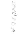
An application field in which the VSF system as shown in FIG. 1 functions is a
[0026]
The
[0027]
The
[0028]
DTMF receiver (receiver) core
The
[0029]
Power calculation
The
[0030]
The best estimate of the signal power of the DTMF signal is made by a Kaiser window or a Kaiser window. Kaiser windows are well known in the digital signal processing art. The basic theory and design of Kaiser windows is described in the following publications:
[0031]
Rabiner, R .; L. , And Gold, B.B. , “Theory and Application of Digital Signal Processing,” Prentice-Hall, Englewood Cliffs, New Jersey (1975). Of course, other types of windows may be used, such as bunlet, Hamming or Blackman windows.
[0032]
A Kaiser window is ideal for determining the power in a pure DTMF signal, as shown by the following analysis. Arbitrarily heref (n), DTMF signals expressed as, can be expressed as follows.
[0033]
f (n) = Acos (ω1n) + Bcos (ω2n)
However, A and B are the amplitudes of the two frequency components.
[0034]
ω1And ω2Is the radial frequency,
ω1> Ω2,
n is the time index
The relative phase of the two signals is not relevant to the analysis and is thus omitted. Square of DTMF signalf (n) 2 , Is as follows.
[0035]
f (n)2= A2cos2(Ω1n) + B2cos2(Ω2n) + 2ABcos (ω1n) cos (ω2n)
However,
[0036]
[Expression 1]
as well as
[0038]
[Expression 2]
So
[0040]
[Equation 3]
The actual power in the DTMF tone signal is 1/2 (A2+ B2). Some Kaiser windows have a frequency of 2ω when transmitting DC1n, 2ω2n, ω1+ Ω2, And ω1−ω2The maximum attenuation is generated. Ω for DTMF1−ω2The lowest value of is 1209-941 = 268 Hz. (See Table 1). Everything except the first component in the above equation drops out (desorbs) and ½ (A2+ B2) Only remains. The 80-tap Kaiser window provides a good stopband rejection (stop band-fail) function outside 268-4000 Hz while DC is transmitted.
[0042]
The outputs of the two
[0043]
Filter design (design)
The 2: 1
[0044]
[0045]
The
[0046]
Each of the filters is implemented as an 82-tap complex FIR filter. The length of 82 is chosen as a trade-off between frequency and time resolution.
[0047]
The filter is optimized for the separation of a single complex exponential component from the effective DTMF signal.
[0048]
The filter used in the
[0049]
f (n) = Acos (ω1n) + Bcos (ω2n) + q (n)
However, q (n) is a white nozzle. ω1For the detection filter, the desired signal is:
[0050]
[Expression 4]
Thus, the noise consists of:
[0052]
[Equation 5]
Ideally, the filter has a good coalesced stop band (stopband), q (n) is minimized and −ω1, Ω2, −ω2Should have a high attenuation. The filter may be designed using least mean square (LMS) recursion, manual manipulation of the matched filter zero position, or any other suitable method. Therefore, good performance with accuracy within% was obtained using manual operation.
[0054]
To design the filter, one can start with a function that represents a matched filter using a truncated complex exponent. This is equivalent to a rectangular low-pass filter having a complex frequency characteristic shifted to a desired center frequency. This type of filter has substantial side lobes, and many lobes are unfavorable noise frequencies (−ω1, Ω2, −ω2Matches).
[0055]
The side lobes can be reduced by using tapered windows or by increasing the window length. However, the DTMF processing time specification substantially limits the length that can be utilized. The tapered window also increases the bandwidth of the main lobe of the frequency response. For relatively low DTMF frequencies, the width expansion is not acceptable.
[0056]
In this example, a length of 10 ms based on the sampling rate has been found to be optimal. DTMF tones were not detected with a relatively short length (5 ms), and severe talk-off problems occurred with a relatively long length (20 ms).
[0057]
Starting from the film function, the zero is located and then adjusted to obtain the desired frequency response.zAssuming a length of N in the region, the filter can be expressed as:
[0058]
[Formula 6]
However, 0 <m <N and i is the square root of -1.
[0060]
Term (1-z ̄1) Is 0 (zero) when z = 1, and corresponds to zero (0) for m = 0 in the numerator term.
[0061]
This gives the following formula:
[0062]
[Expression 7]
The rectangular window complex filter has the following pulse response.
[0064]
[Equation 8]
h (n)ofzThe conversion is as follows:
[0066]
[Equation 9]
However, C is not relevant to the design because it is a constant unit quantity.
[0068]
Against the filterzExpanding the transformation, the frequency response is a commonly available quality program such as ILS (Signai Technology, Inc., Goleta, Calif.). Can be plotted. This identifies which 0 (zero) must be moved. Multi-order division can be used as a tool for removing zero (0) and multi-order multiplication can be used to add zero (0).
[0069]
The purpose is to collect or cluster (zero) zeros (0) near the positive and negative frequencies of the alternating frequency group. For example, for a low band frequency (
[0070]
Filter operation
The even input samples generated by the 2: 1
[0071]
The outputs of the low band value squaring (function) function units 210, 212, 214, 216 are inputs to the low
[0072]
There, the odd sample output of the 2: 1
[0073]
Depending on the results of the low and high
[0074]
At that point, the odd and even samplings are recombined to recreate the original (first) sample at 8000 per second. The low
[0075]
The output of the low band value squaring (function)
[0076]
Evaluation algorithm
The
The
The output 236 of the
80: 1
80: 1 filter output decimator 262 output 266 (which represents discrete highband tone signal power ("Y"))
The
[0077]
Each sample checked by the
1 = pure DTMF with no measurable strain
2 = DTMF with a small amount of measurable strain
3 = DTMF with significant (substantial) strain
4 = Signal is not DTMF
Each test (check) performed by the
[0078]
During operation, one sample undergoes all tests (checks) using level 1 parameters. If the sample passes the test (check), it is assigned a rating of 1. However, if the sample fails any of the level 1 tests (checks), the test (check) is executed for level 2. On the other hand, if the level 2 test (check) is ineligible (failed), the
[0079]
To pass the test (check) imposed by the
[0080]
There are seven tests (checks) in the evaluation algorithm 54: a signal-to-signal + noise ratio check, called SSNR,
Three normality checks (tests) referred to as Sanityl, Sanity2, and Sanity3, respectively, and two twist checks (tests) referred to as Twistl and Twist2, respectively, Totalpower. One power check (test) called. SSNR, Twistl, Twist2, and TotalPower verify the attributes (characteristics) that all DTMF signals should have. The seven tests (checks) are listed as follows.
[0081]
X is the squared output of the low-band filter
Y is the squared output of the high band filter
P is the rectangular window total (total) signal power
W is Kaiser window total (total) signal power
Depending on the normality test, it is ensured that the total (total) signal power (power) includes only the sum of the contribution components of each tone and does not include other spurious components.
[0082]
According to the normality test, the following attributes are verified, that is, the attributes that the stationary signal has but not the unsteady signal are verified. For example, if the signal power is concentrated in the first and last group of samples that verify the non-DTMF signal, the Kaiser windowed signal power estimate W is low. However, the power P subjected to the rectangular window processing is used as a check for verifying the actual power level.
[0083]
Twist is the difference in amplitude of the high and low frequency components of the DTMF signal. The high frequency tone is usually set higher than 2 dB because the high frequency decreases more quickly than the low frequency on the telephone line. Thus, the twist is nominally 2 dB. According to the EIA specification, an acceptable (qualified) -DTMF signal can have a twist ranging from +4 to -8 dB. Therefore, level 1 parameters should be chosen to allow such a degree of change.
[0084]
Parameters (param1, Param2, Param3, Param4, Param5, Param6, And MinPower) are empirically selected to empirically optimize talk-off performance. In order to obtain the values of these parameters, each of the seven tests is performed using a sample composite of DTMF, a speech DTMF acoustic coupler DTMF. The parameters are adjusted until each test passes the desired performance at each of the three levels. It should be noted that the goal of the selection process is to minimize talkoff.
[0085]
At the first level representing pure DTMF, the input sample is the ETA standard DTMF. Each parameter is adjusted until the sample passes a minimum of each test. The test is then performed at a third level representing the acoustic coupler DTMF. Acoustic Coupler Generation—Using DTMF samples, the parameters are adjusted again until they pass the test, and the values are selected to be minimally passed. In addition, the parameters are selected for the second level (medium quality DTMF) using speech DTMF input samples. By observing the characteristics of the system and using approximations, an optimal parameter set can be selected for such signals.
[0086]
In addition, a separate parameter may be specified for each DTMF value, since the predetermined associated frequency exhibits different characteristics for each of the tests of the
[0087]
If necessary, the SSNR and Sanity 1 tests can be performed using a rectangular window or some other power detection pattern (method). Thus, for a rectangular window output, the test is as follows.
[0088]
[0089]
Timing / stability algorithm
[0090]
The timing / stability algorithm 56 verifies the following: verify that the signal is long enough to be a DTMF signal and exists with sufficient consistency. For example, the DTMF signal is required to be the same over the entire period of interest (important). The human voice cannot maintain a constant output for a long time while the DTMF generator delivers a stable (stationary) signal, so the algorithm helps to distinguish between speech and DTMF and is not captured by the
[0091]
In contrast to the frequency
[0092]
The following empirically determined parameters exist for the inputs P, X, Y, and Z, that is, the minimum of a predetermined input (DTMF is valid for this predetermined input) There is an empirically defined parameter that is the ratio of the value to the maximum value. In this embodiment, there are three levels as follows: there are three levels with DTMF quality grades ranging from the highest to the lowest acceptable (qualified) DTMF quality. . Thus, each input monitored by the timing / stability algorithm 56 has a set of three parameters. In addition, for each level, the algorithm 56 has a capture period,
30 ms for level 1
40ms for level 2,
70 ms change for
Let When the input min / max ratio exceeds the parameters specified in the design specification for a given level, the algorithm assumes and assumes that the input signal does not pass the level. (Not eligible), move to next level, proceed (until level (non-DTMF) is reached).
[0093]
In practice, the minimum / maximum ratio can be compared to a parameter using the following formula or relationship, that is, a parameter using the formula or relationship such that minimum value> parameter maximum value.
[0094]
When evaluating the stability of the quality evaluation (by the evaluation algorithm 54), the algorithm 56 searches for the lowest evaluation (highest number) in the history characteristics. Starting from the first level, the algorithm 56 checks (scans) for any alerts (responses) lower than level 1. If so, the level 1 test (check) fails and the algorithm 56 checks a larger (relatively larger) sample set (for a period of 40 ms) and reports below level 2 Check whether there is (response) (for example, 3) or not. If level 2 is not satisfied, algorithm 56 moves to
[0095]
A test for the stability of the DTMF value can determine whether there is a change in value during the capture period (30, 40, or 70 ms). If the DTMF value changes for that level sometime during the period, the signal is rejected (failed) as talk-off and the next level is tested.
[0096]
When the analysis is complete, the timing / stability algorithm 56 issues a stability rating 1-4 for each input, depending on which level was successfully completed. It should be noted that the quality evaluation stability test requires that the timing / stability evaluation does not exceed any of the evaluations in the history characteristics. Thus, if the history characteristic is a series of evaluations (1, 2, 3, 4), the highest evaluation given by it is 3.
[0097]
By executing the algorithm 56 using the same sampling composite of DTMF, speech DTMF, talkoff, and acoustic coupler DTMF, ratio values for P, W, X, and Y are selected empirically. The ratio is adjusted until it passes the test (check) for the desired performance at each of the three levels for a given DTMF value.
[0098]
The timing / stability algorithm 56 may use a selective means of stability evaluation. For example, instead of using the ratio between the maximum value and the minimum value, standard deviations of P, W, X, and Y can be used.
[0099]
Second timing algorithm
The output of the timing / stability algorithm 56 is supplied to the second timing algorithm 58. The algorithm detects the beginning and end of the DTMF signal, thereby producing a single DTMF response for each telephone key press. Its function is to avoid unnecessary outages caused by short “dropouts”.
[0100]
The second timing algorithm 58 has two states: an idle state and an active state. In the idle state, the algorithm 58 responds to
[0101]
Algorithm interaction
In order to check how the four algorithms (52, 54, 56, 58) achieve talk-off prevention, it is advantageous to consider human speech in the context of testing the algorithms. Human speech can be modeled as a time-varying pulse train generator that provides time-varying filter characteristics.
[0102]
The pulse train generator forms a line in a narrow spectrum of equal amplitude. Depending on the filter, the spectral lines have a different height, and the filter has a limited q, so adjacent spectral lines have comparable amplitudes. However, widely separated spectral lines can have a wide variety of different amplitudes. Further, the filter has a low-pass filter characteristic (since the low frequency has a larger amplitude than the high frequency (f> 2000 Hz)).
[0103]
Friction and plosives are not taken into account because it is known that there is no pitch and experience does not cause talk-off. Since human voice has a limited high frequency component and the telephone handset has a limited low frequency (below 500 Hz) response characteristic, the low frequency component is limited by the phone. Therefore, most of the signal power for the audio signal is concentrated in the same bandwidth as the DTMF signal.
[0104]
The purpose of the four algorithms (52, 54, 56, 58) is to detect the presence of significant signal power that may be near either or both of the DTMF frequency bands, ie not a valid DTMF signal. When the ineffective signal is excessively close (close) to the DTMF frequency, it is included in the amplitude estimation value for the frequency. However, the filter contains two compound exponentials (exponential components) instead of one, and causes either or both of the Sanityl and SSNR tests to fail (depending on the relative phase of the two frequencies). ). That signal also fails the timing / stability algorithm 56.
[0105]
If the jamming signal has sufficient amplitude, the DTMF value will get into fluctuation. The SSNR test will fail if the signal power is far enough from the DTMF band to be separated by the filter.
[0106]
Acoustic (Actic) transmitter adaptation adjustment
If the generator is an acoustic coupling device, four algorithms (52, 54, 56, 58) can be augmented (enhanced) to improve DTMF detection. The acoustic coupling DTMF generator can be modeled as a
[0107]
Since the DTMF signal from the acoustic transmitter is usually longer than the DTMF signal generated by another source, the DTMF from the acoustic transmitter is usually evaluated in three evaluations from both the
[0108]
Since the frequency domain analysis in the DTMF
[0109]
[Table 1]
Those frequencies are within 100 Hz of one of the generated DTMF frequencies.
[0111]
The tests performed by the algorithm can be relaxed by using relatively non-restrictive parameters for
[0112]
As can be appreciated, alleviation of the severity of the test leads to more frequent talk-off phenomena. In order to avoid an increase in talk-off related failures, the number of effective DTMF signals that can be used during a critical period of talk off can be limited. For example, during such a time interval, the user interface can be designed to reject DTMF values of 2, 3, 6, B, and C when recording audio, for example. The other 11 DTMF signals (0, 1, 4, 5, 7, 8, 9, *, #, A, and D) are available (even if the user is busy) The system must still accept DTMF. As a further note, it is advisable to limit the acceptable DTMF signals to X and O during that time. Furthermore, mutual improvements can be made by adjusting a finite transformer hybrid lossy bandpass filter.
[0113]
Finite transformer hybrid loss filtering
The performance deficit caused by finite transformer hybrid loss can be reduced by removing the band periphery. A
[0114]
Action
The operation of the apparatus will be described with reference to the flowcharts in FIGS. In the following description, the numbers in parentheses represent the number of boxes in the flowchart, while the numbers not in parentheses refer to the elements shown in FIGS. 1-3 and described above.
[0115]
Beginning with FIG. 4, the analog input is sampled and the resulting 8000 digital signal per second is provided to the DTMF receiver core (300). This signal passes through the
[0116]
Two power calculations are performed.
[0117]
The frequency measurement phase begins with a signal that is divided by the 2: 1 decimator 142 into odd and even samples. The even samples are filtered by the low band section 152 filter and the
[0118]
The combined output is then squared in value to indicate the respective power in each of the two DTMF signal tones. This signal is also decimated by the 80: 1 decimators 260, 262 (236). The outputs are referred to as “X” and “Y” and represent low and high bands, respectively.
[0119]
This completes the processing by the
[0120]
Initially, the
[0121]
However, if any of the above tests fail from the sample, the parameter level is incremented until level 4 is reached, and the test is run at a new level for a given DTMF value (342-348). . If the sample passes all of the tests, the
[0122]
The timing / stability algorithm 56 receives the following inputs as shown in FIG. 6; rating, specified by the
[0123]
Initially, the algorithm is initialized to level 1. The input is received and stored, history characteristic quantities are accumulated (370), and the algorithm selects DTMF values and parameters for a predetermined level. Each input is then tested for stability using a ratio of maximum and minimum values as described above for a given DTMF value.
[0124]
There are predetermined time intervals and parameters for each level. Each of the inputs is examined at a first level to determine whether the test is satisfied. If the input passes the first level of the test (380), the timing / stability algorithm 56 assigns an evaluation of 1 (382). If all of the tests fail, the algorithm 56 falls to the next level, updates the history (384, 388), etc. (until the fourth level is reached) (386). However, despite the assigned stability rating, the final rating is not higher than the quality rating issued by the
[0125]
The timing / stability algorithm 56 passes the 1-4 rating and moves to the second timing algorithm 58. Initially (initially), the second timing algorithm 58 is in an idle state (idle state) (400). However, upon receiving a rating of 1, 2 or 3, the algorithm moves to active mode (404), a DTMF value is emitted, and a counter that monitors signal dropout is initialized to zero count (406).
[0126]
Once active, the second timing algorithm 58 begins checking for the end of the DTMF signal by examining changes in the DTMF value or rating of 4. Every time a new sample is received, that is, every 10 ms, the algorithm cyclically performs the search (search operation) (408). Assuming no change, the counter is maintained at zero (410) and the check is repeated continuously every 10 ms.
[0127]
When the second timing algorithm 58 finds a change in DTMF value or rating of 4, the counter starts operation and is incremented by one count. The counter continues to increment while the rating remains at 4 and / or the current DTMF value differs from the original (original) value. After each increment of the counter, the second timing algorithm 58 checks whether the count has reached the dropout count (414). Reaching the dropout count indicates that the DTMF signal has ended (416). The algorithm then returns to the idle state (400).
[0128]
If the rating is 1, 2 or 3 and / or the DTMF value returns to the original (original) value before the dropout count is reached (414), the second timing algorithm 58 detects the change (408). The counter is reset to zero (410) and the check is resumed for another change (408).
[0129]
While advantageous embodiments of the invention have been described, it will be apparent to those skilled in the art that other and further variations and modifications can be made without departing from the spirit of the invention. Embodiments falling within the scope of For example, evaluation parameters, timing values, and bandpass filter performance can be changed. The
[0130]
【The invention's effect】
In accordance with the present invention, improved talk-off performance of telephone equipment such as VSF equipment, and improved identification (recognition) performance of DTMF receivers used in acoustically coupled DTMF generators and finite transformer hybrid losses The advantage of effectively implementing (implementing) the system or method using a digital signal processing technique can be obtained by reducing the effect of.
[Brief description of the drawings]
FIG. 1 is a block connection diagram of a configuration of a telephone system according to the present invention.
FIG. 2 is a block connection diagram of a DTMF detection system.
FIG. 3 is a block connection diagram of a DTMF receiver core.
FIG. 4 is a flow diagram of a DTMF receiver core algorithm.
FIG. 5 is a flowchart of a preceding evaluation algorithm for sampling and bandpass filtering function operation.
FIG. 6 is a flowchart of a timing / stability algorithm.
FIG. 7 is a flowchart of a second timing algorithm.
FIG. 8 is a block connection diagram of an acoustic coupling DTMF transmitter.
[Explanation of symbols]
10 Public communication network
12 Telephone line
14 VSF
16 transformer hybrid circuit
18 Sampling equipment
20 DTMF detection system
24 Audio output device
26 Transmission line
Claims (12)
前記システムは、
電力特性及び周波数特性を含む前記信号の信号特性の指標を得るために前記信号を処理する手段(52)と、
前記所定のマッピングに従って前記周波数特性の指標から前記信号を識別し、前記信号の識別値を求める手段(52)と、
前記信号を2より多くの品質レベルにより評価する手段(54)と、
前記信号の評価の安定性に基づいて複数の期間にわたって前記信号の安定性を求める手段(56)とを有し、
前記評価手段(54)は、評価パラメータの複数のセットを使用し、該評価パラメータの複数のセットは、それぞれ異なる識別値グループに対する評価パラメータの別個のセットを含んでおり、前記手段(54)は、前記評価パラメータのセットから選択されたセットを用いて、電力特性を含む前記信号の信号特性を評価することにより前記信号を評価し、前記選択されたセットは、当該セットと前記信号の求められた識別値が属する識別値グループとの間の対応に従って選択されており、
前記安定性を求める手段(56)は安定性パラメータの複数のセットを使用し、該安定性パラメータの複数のセットは、それぞれ異なる識別値グループに対する安定性パラメータの別個のセットを含んでおり、
前記信号評価及び前記信号安定性は、前記信号の求められた識別値の信頼性の指標である、ことを特徴とする複数信号の検出及び識別システム。A detection and identification system several signals, each of said signal has a first and a second component, each such component has a predetermined frequency, said first and second signals is the signal In a system of a type that has an identification value corresponding to a predetermined frequency of the component , the correspondence being in accordance with a predetermined mapping that associates a combination of frequencies with the identification value,
The system
Means (52) for processing the signal to obtain an indication of signal characteristics of the signal including power characteristics and frequency characteristics;
Means (52) for identifying the signal from the index of the frequency characteristic according to the predetermined mapping and obtaining an identification value of the signal;
Means (54) for evaluating said signal by more than two quality levels;
Means (56) for determining the stability of the signal over a plurality of periods based on the stability of the evaluation of the signal;
The evaluation means (54) uses a plurality of sets of evaluation parameters, wherein the plurality of sets of evaluation parameters includes a separate set of evaluation parameters for different distinct value groups, the means (54) Evaluating the signal by evaluating a signal characteristic of the signal including a power characteristic using a set selected from the set of evaluation parameters, wherein the selected set is obtained for the set and the signal. Selected according to the correspondence with the identification value group to which the identification value belongs,
The means for determining stability (56) uses a plurality of sets of stability parameters, the plurality of sets of stability parameters including a separate set of stability parameters for each different discriminant value group;
The multiple signal detection and identification system, wherein the signal evaluation and the signal stability are indicators of the reliability of the identification value obtained for the signal.
前記評価パラメータの複数のセットは、DTMF識別値{2,3,6,B,C}の各々に対する第1のパラメータセットと、DTMF識別値{0,1,4,5,7,8,9,*,♯,A,D}の各々に対する第2のパラメータセットとを含んでおり、
前記安定性パラメータの複数のセットは、DTMF識別値{2,3,6,B,C}の各々に対する第1のパラメータセットと、DTMF識別値{0,1,4,5,7,8,9,*,♯,A,D}の各々に対する第2のパラメータセットとを含んでいる、請求項1記載のシステム。The signal is a DTMF signal;
The plurality of sets of evaluation parameters include a first parameter set for each of the DTMF identification values {2, 3, 6, B, C} and a DTMF identification value {0, 1, 4, 5, 7, 8, 9 , *, #, A, D} each including a second parameter set,
The plurality of sets of stability parameters include a first parameter set for each of the DTMF identification values {2, 3, 6, B, C}, and DTMF identification values {0, 1, 4, 5, 7, 8, And a second parameter set for each of 9, *, #, A, D}.
前記信号の電力成分の第1及び第2の測定を同時に行う手段と、
所定のパラメータに従って前記第1の測定(結果)を前記第2の測定(結果)と比較する手段とを有する、請求項1記載のシステム。 The means (54) for evaluating the signal comprises :
Means for performing a first and a second measurement of the power component of the signal at the same time,
The first measurement and a means that compares the (Results) the second measurement (result), system of claim 1 in accordance with predetermined parameters.
前記電力成分の変化を検出する手段は、
複数の期間のうちの1つにわたって前記信号の電力成分の最小値及び最大値を求める手段と、
前記最小値と前記最大値を比較する手段とを有する請求項1記載のシステム。 The means for determining the stability of the signal comprises means for detecting a change in the power component ;
The means for detecting a change in the power component is :
Means for determining a minimum and maximum value of the power component of the signal over one among a plurality of periods,
The system of claim 1 further comprising a means for comparing the maximum value and the minimum value.
前記システムは、
前記信号内の成分周波数を検出し、前記所定のマッピングに基づいて前記成分周波数を評価することにより前記信号を識別する手段(52)と、
2より多くの品質レベルにより前記信号を評価する評価手段(54)とを有し、
前記評価手段は評価パラメータの複数のセットを使用し、異なる識別値グループに対して別個の評価パラメータのセットが設けられており、前記評価手段(54)は、評価パラメータの前記セットから選択されたセットを用いて電力特性を含む前記信号の信号特性を評価することにより前記信号を評価し、前記選択されたセットは、該セットと前記信号の識別値が属する識別値グループとの間の対応に従って選択されている(340)、ことを特徴とする複数信号の検出及び識別システム。A detection and identification system several signals, each signal having first and second components, the respective components having a predetermined frequency, said first and second components of each signal the signal in the has an identification value corresponding to a predetermined frequency, form the support is in accordance with a predetermined mapping for the combination of the frequency identification value system,
The system
Means (52) for identifying the signal by detecting a component frequency in the signal and evaluating the component frequency based on the predetermined mapping;
Evaluation means (54) for evaluating said signal with a quality level of more than two,
The evaluation means uses a plurality of sets of evaluation parameters, and a separate set of evaluation parameters is provided for different discriminating value groups, the evaluation means (54) selected from the set of evaluation parameters Evaluating the signal by evaluating a signal characteristic of the signal including a power characteristic using a set, the selected set according to a correspondence between the set and an identification value group to which the identification value of the signal belongs; A multi-signal detection and identification system, characterized in that it is selected (340) .
Applications Claiming Priority (2)
| Application Number | Priority Date | Filing Date | Title |
|---|---|---|---|
| US90344092A | 1992-06-24 | 1992-06-24 | |
| US07/903440 | 1992-06-24 |
Publications (2)
| Publication Number | Publication Date |
|---|---|
| JPH0678345A JPH0678345A (en) | 1994-03-18 |
| JP3623973B2 true JP3623973B2 (en) | 2005-02-23 |
Family
ID=25417511
Family Applications (1)
| Application Number | Title | Priority Date | Filing Date |
|---|---|---|---|
| JP15341293A Expired - Fee Related JP3623973B2 (en) | 1992-06-24 | 1993-06-24 | Multiple signal detection and identification system |
Country Status (3)
| Country | Link |
|---|---|
| US (1) | US5528663A (en) |
| EP (1) | EP0579927A2 (en) |
| JP (1) | JP3623973B2 (en) |
Families Citing this family (13)
| Publication number | Priority date | Publication date | Assignee | Title |
|---|---|---|---|---|
| US5535271A (en) * | 1994-05-27 | 1996-07-09 | Hughes Electronics | Apparatus and method for dual tone multifrequency signal detection |
| DE19531829C2 (en) * | 1995-08-15 | 1997-08-28 | Stefan Hahn | Method and device for pulse dialing detection when there is a call |
| US5689556A (en) * | 1995-09-15 | 1997-11-18 | Hughes Electronics | Method of detecting narrow-band signals in an echo canceller |
| US5889851A (en) * | 1996-02-26 | 1999-03-30 | Lucent Technologies Inc. | DTMF signal detection/removal using adaptive filters |
| US5995557A (en) * | 1997-06-12 | 1999-11-30 | Nortel Networks Corporation | Tone detection with aliasing bandpass filters |
| US6157712A (en) * | 1998-02-03 | 2000-12-05 | Telefonaktiebolaget Lm Ericsson | Speech immunity enhancement in linear prediction based DTMF detector |
| US6347134B1 (en) | 1998-02-05 | 2002-02-12 | Picazo Communications | Recording and playing voicemail with improved DTMF detection |
| US6148077A (en) * | 1998-08-26 | 2000-11-14 | Pocket.Com, Inc. | System and method for providing user feedback to couple an electronic device with a telephone handset |
| US6438224B1 (en) * | 1998-11-12 | 2002-08-20 | Nms Communications Corporation | Tone detection |
| US6757276B1 (en) * | 1998-11-24 | 2004-06-29 | 3Com Corporation | Touch tone replacement for internet telephony |
| JP3786842B2 (en) * | 2001-03-30 | 2006-06-14 | 三菱電機株式会社 | Audio transmission device |
| JP4854877B2 (en) * | 2001-07-03 | 2012-01-18 | 富士通セミコンダクター株式会社 | Push button signal receiving apparatus and push button signal detecting method |
| US7805119B2 (en) * | 2007-05-02 | 2010-09-28 | D.S.P. Group Ltd. | Multi-frequency detector |
Family Cites Families (10)
| Publication number | Priority date | Publication date | Assignee | Title |
|---|---|---|---|---|
| US4354248A (en) * | 1979-11-28 | 1982-10-12 | Motorola, Inc. | Programmable multifrequency tone receiver |
| US4580016A (en) * | 1984-09-24 | 1986-04-01 | Vmx, Inc. | Method and apparatus for checking the integrity of a communications channel in a voice store and forward system |
| US4599495A (en) * | 1985-02-28 | 1986-07-08 | Northern Telecom Limited | Apparatus for multifrequency signalling tone detection |
| US5073941A (en) * | 1988-02-01 | 1991-12-17 | Ibm Corporation | Multifrequency detection |
| CA1289281C (en) * | 1988-05-05 | 1991-09-17 | Jerry Stroobach | Digital dtmf tone detector |
| US4853958A (en) * | 1988-06-02 | 1989-08-01 | Northern Telecom Limited | LPC-based DTMF receiver for secondary signalling |
| US4833399A (en) * | 1988-06-13 | 1989-05-23 | Texas Instruments Incorporated | DTMF receiver |
| US4903292A (en) * | 1988-11-01 | 1990-02-20 | Reliance Comm/Tec Corporation | System for transmitting low frequency tones through a digital loop carrier system |
| US5203011A (en) * | 1990-09-04 | 1993-04-13 | Motorola, Inc. | Method and apparatus for establishing voice and tone signalling communication in a trunked system |
| US5163050A (en) * | 1991-01-23 | 1992-11-10 | Digital Sound Corporation | Configurable parameter dtmf detector |
-
1993
- 1993-05-24 EP EP93108380A patent/EP0579927A2/en not_active Withdrawn
- 1993-06-24 JP JP15341293A patent/JP3623973B2/en not_active Expired - Fee Related
-
1995
- 1995-07-26 US US08/508,789 patent/US5528663A/en not_active Expired - Lifetime
Also Published As
| Publication number | Publication date |
|---|---|
| EP0579927A2 (en) | 1994-01-26 |
| EP0579927A3 (en) | 1994-08-31 |
| US5528663A (en) | 1996-06-18 |
| JPH0678345A (en) | 1994-03-18 |
Similar Documents
| Publication | Publication Date | Title |
|---|---|---|
| EP0575725B1 (en) | Adaptive signal detection process for the evaluation of multifrequency coded signals | |
| JP3623973B2 (en) | Multiple signal detection and identification system | |
| US4689760A (en) | Digital tone decoder and method of decoding tones using linear prediction coding | |
| EP0153787B1 (en) | System of analyzing human speech | |
| JP3066213B2 (en) | Control signal detection method | |
| JP2597817B2 (en) | Audio signal detection method | |
| EP0647375B1 (en) | Method and apparatus for objective speech quality measurements of telecommunication equipment | |
| US6396851B1 (en) | DTMF tone detection and suppression with application to computer telephony over packet switched networks | |
| US4809272A (en) | Telephone switching system with voice detection and answer supervision | |
| JPH0730930A (en) | Dual tone detector allowing operation under presence of voice or background noise and its method | |
| US5970447A (en) | Detection of tonal signals | |
| US5214693A (en) | Multi-frequency signal receiver and a method of detecting the multi-frequency signal | |
| US5257309A (en) | Dual tone multifrequency signal detection and identification methods and apparatus | |
| US5426696A (en) | Method of improving receiver sensitivity and speech immunity with DTMF-reception | |
| JPH06504890A (en) | DTMF signal detection device | |
| JP2593901B2 (en) | Circuits for voice signal characterization and systems for telephone line monitoring | |
| JP3266605B2 (en) | Touchtone recognition device and method | |
| US4990848A (en) | DTMF receiver | |
| US8050397B1 (en) | Multi-tone signal discriminator | |
| US5353345A (en) | Method and apparatus for DTMF detection | |
| US5136531A (en) | Method and apparatus for detecting a wideband tone | |
| US6199036B1 (en) | Tone detection using pitch period | |
| JPS6238097A (en) | Receiver | |
| JPS59501437A (en) | Adaptive signal reception method and device | |
| CN101635865B (en) | System and method for preventing error detection of dual-tone multi-frequency signals |
Legal Events
| Date | Code | Title | Description |
|---|---|---|---|
| TRDD | Decision of grant or rejection written | ||
| A01 | Written decision to grant a patent or to grant a registration (utility model) |
Free format text: JAPANESE INTERMEDIATE CODE: A01 Effective date: 20041029 |
|
| A61 | First payment of annual fees (during grant procedure) |
Free format text: JAPANESE INTERMEDIATE CODE: A61 Effective date: 20041129 |
|
| R150 | Certificate of patent or registration of utility model |
Free format text: JAPANESE INTERMEDIATE CODE: R150 |
|
| LAPS | Cancellation because of no payment of annual fees |