JP3623632B2 - Vacuum cleaner vacuum cleaner with wiping function - Google Patents
Vacuum cleaner vacuum cleaner with wiping function Download PDFInfo
- Publication number
- JP3623632B2 JP3623632B2 JP08198397A JP8198397A JP3623632B2 JP 3623632 B2 JP3623632 B2 JP 3623632B2 JP 08198397 A JP08198397 A JP 08198397A JP 8198397 A JP8198397 A JP 8198397A JP 3623632 B2 JP3623632 B2 JP 3623632B2
- Authority
- JP
- Japan
- Prior art keywords
- suction port
- suction
- holder
- elastic member
- attached
- Prior art date
- Legal status (The legal status is an assumption and is not a legal conclusion. Google has not performed a legal analysis and makes no representation as to the accuracy of the status listed.)
- Expired - Fee Related
Links
Images


Description
【0001】
【発明の属する技術分野】
本発明は、真空掃除機用の吸込み具に関するものであり、さらに詳しくは、拭布による払掃機能を備えた真空掃除機用吸込み具に関するものである。
【0002】
【従来の技術】
従来より公知の真空掃除機用吸込み具は、一般に、下面にごみの吸込口を有すると共に、この吸込口の周辺にブラシを有し、この吸込み具を前後あるいは左右に摺動させることにより、ブラシで掃き集めたごみを吸込口から吸込んで捕集するものである。
【0003】
しかしながら、上記従来の吸込み具は、床面上のごみを吸込むのには適しているものの、床面に付着した汚れを落とすのは殆ど不可能に近く、このため、真空掃除機により床面上のごみを吸込んで除去した後に、雑巾やモップ等で床面に付着した汚れを拭き取らなければならなかった。
この結果、複数の異なる方法による清掃を行わなければならないため、手間がかかって清掃作業が非常に面倒であるばかりでなく、清掃用具も複数種類用意しなければならないために不経済であった。
【0004】
【発明が解決しようとする課題】
本発明の主要な技術的課題は、床面上のごみを吸い取る機能と、床面に付着した汚れを拭き取る機能とを兼備した、構造が簡単で効率的な真空掃除機用吸込み具を提供することにある。
【0005】
本発明の他の技術的課題は、大小のごみを吸込口から吸い込んだあとを拭布で払拭清掃することができる、清掃効率の良い真空掃除機用吸込み具を提供することにある。
【0006】
本発明の他の技術的課題は、汚れを拭き取るための拭布の着脱が容易な、取扱い性に勝れた真空掃除機用吸込み具を提供することにある。
【0007】
【課題を解決するための手段】
上記課題を解決するため、本発明の真空掃除機用吸込み具は、ごみの吸込口を備えたヘッド部と、上記吸込口を真空掃除機の吸引ホースに接続するための接続管部とからなり、上記ヘッド部における吸込口内には、該吸込口を左右に横断するプレート状をしたホルダが、該吸込口内を前後方向に移動自在かつ該吸込口から取り出し自在なるように取り付けられ、該ホルダの下面に板状をした拭布取付用の弾性部材が取り付けられると共に、該弾性部材に拭布が着脱自在に取り付けられていることを特徴とするものである。
【0008】
また、本発明の他の真空掃除機用吸込み具は、ごみの吸込口を備えたヘッド部と、上記吸込口を真空掃除機の吸引ホースに接続するための接続管部とからなり、上記ヘッド部における吸込口内には、該吸込口を左右に横断するプレート状をしたホルダが、該吸込口内を前後方向に移動自在なるように取り付けられ、該ホルダは、上記吸込口内を移動する第1部材と、該第1部材に取り付けられた第2部材とからなっていて、該第2部材に板状をした拭布取付用の弾性部材が取り付けられると共に、該弾性部材に拭布が着脱自在に取り付けられており、また、上記第2部材は、上記拭布の着脱を行うための位置に移動自在であることを特徴としている。
【0009】
上記構成の吸込み具は、接続管部を真空掃除機の吸引ホースに接続して、通常の吸込み具と同様に、床面上を往復動させることにより清掃を行う。このとき、床面上のごみは弾性部材の両側の開口部分から吸引され、床面上に付着した汚れは、上記弾性部材に取付けた拭布により拭き取られる。
【0010】
この結果、真空掃除機による一回の清掃によってごみの吸引と拭布による払掃との両方を同時に行うことができ、清掃作業が簡単で効率的である。しかも、拭布の両側に吸込口の開口部分が形成されるため、吸込み具を往復何れの方向に動かす場合でも、開口部分でごみを吸い取ったあとの汚れを上記拭布で拭くことになり、非常に効率良く清掃を行うことができる。また、吸込口内に弾性部材を設けて拭布を取り付けるだけであるから、吸込み具としての構造も簡単である。
【0011】
本発明において好ましくは、上記弾性部材が、上面中央部周辺だけを部分的に上記ホルダの下面に接着されていて、前後端の非接着部とホルダとの間に拭布の端部を挟持するための止着部が形成されていることである。
【0012】
また、本発明においては、上記吸込口がホルダ及び弾性部材によって前後2つの開口部分に区画され、清掃時に吸込み具を前後動させた際に、上記ホルダ及び弾性部材が移動することにより、吸込み具の移動方向前方側の開口部分が開放し、後方側の開口部分が閉塞されるように構成されている。
【0013】
【発明の実施の形態】
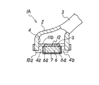
図1乃至図3は、本発明に係る真空掃除機用吸込み具の第1実施例を示すもので、この第1実施例の吸込み具1Aは、ごみの吸込口4を下面に備えた横長のヘッド部2と、該ヘッド部2の上面中央部付近から斜め後方に向けて延びる、上記吸込口4を真空掃除機の吸引ホースに接続するための接続管部3とからなっている。
【0014】
上記ヘッド部2における吸込口4の内部には、該吸込口4を左右に横断するようにプレート状をしたホルダ5が設けられ、該ホルダ5の下面に、板状をした拭布取付用の弾性部材6が、上記吸込口4を前後2つの開口部分4a,4bに区画するように平面を上下方向に向けて横向きに取り付けられ、この弾性部材6に、不織布等の繊維素材からなる払掃用の拭布7が着脱自在に装着されている。
【0015】
上記ホルダ5は、金属や合成樹脂等の硬質素材からなるもので、吸込口4の前後幅より狭い板幅を持ち、その長手方向の両端が、ヘッド部2における左右の側壁10,10の内側面に前後方向に切設された支持溝11a,11b内に摺動自在に嵌合することにより、吸込口4内を前後方向に移動自在となっている。そして、該ホルダ5が吸込口4の中間部に位置するときは、その両側に第1及び第2の開口部分4a,4bが開口し、上記ホルダ5が吸込口4の前後何れかの側に移動すると、その移動した側の開口部分が閉塞されるようになっている。
【0016】
一方、上記弾性部材6は、合成樹脂発泡体やゴム等の柔軟性を有する弾性素材により、上記ホルダ5とほぼ同じ幅か又は大きい幅に形成されて、該ホルダ5の下面に接着テープ等の取付手段12により取り付けられている。この場合、該弾性部材6の全面をホルダ5に接着することなく、図示したように中央部周辺だけを部分的に接着することにより、前後端の非接着部6aとホルダ5とによって止着部を構成し、それらの間に拭布7の端部を挟持できるようにしておくことが望ましく、これにより、拭布7の装着を確実にして該拭布7が吸込口4から吸い込まれるのを防止することができる。
また、上記弾性部材6は、清掃していない状態で下端部が吸込み具1Aの側壁下端の接地部10aよりも若干下方に突出するように配設されており、これにより、清掃時に拭布7を床面に適度の力で押し付けることができるようになっている。
【0017】
上記弾性部材6に拭布7を着脱する作業は、該弾性部材6が吸込口4内に位置する状態のまま行うこともできるが、作業を容易にするため、該弾性部材6を吸込口4から全部又は一部が露出する着脱位置に移動させた状態で行うようにすることが望ましい。このため上記第1実施例においては、該弾性部材6をホルダ5と一緒に外部に取り出せるようにしている。
【0018】
即ち、図1に示すように、上記ホルダ5の両端が嵌合する支持溝11a,11bのうちの少なくとも一方の支持溝11aの深さを深くし、側壁10の内面で弾性部材6を圧縮しながらホルダ5を該支持溝11a内に一旦押し込むことによって、該ホルダ5の他端を反対側の支持溝11bから外して吸込口4の外に取り出し、そのあと該ホルダ5を反対方向へ移動させて反対側の端部を上記支持溝11aから抜き取ることにより、該ホルダ5及び弾性部材6を吸込口4から取り出すことができるようになっている。
上記ホルダ5を取り外す必要がないときは、上記弾性部材6が側壁10の内面に当接してホルダ5の動きを規制するため、該ホルダ5が不時に外れることはない。
【0019】
図4は上記ホルダ5の取り出しを可能にする機構の他の実施例を示すもので、この第2実施例のホルダ1Bにおいては、支持溝11aの溝底壁11cを溝深が変化する方向(内外方向)に変移自在とし、ばね14で外側に向けて付勢したもので、この溝底壁11cをホルダ5で押圧することによって図1の場合と同様にして該ホルダ5を取り出すことができるものである。
【0020】
上記構成を有する吸込み具1A,1Bは、接続管部3を真空掃除機の吸引ホースに接続して、通常の吸込み具と同様に、床面上を前後方向に往復動させることにより清掃を行う。このとき、床面上のごみは、弾性部材6の前方又は後方に開口する開口部分4a,4bを通じて吸引され、床面上に付着した汚れは、上記弾性部材6に取付けた拭布7により拭き取られる。
【0021】
この点について更に詳しく説明すると、図3に示すように吸込み具1A,1Bが前進するときは、拭布7と床面との摩擦によってホルダ5が支持溝11a,11b内を後方に向けて相対的に移動し、第2開口部分4bを閉塞するため、前方の第1開口部分4aを通じてごみが吸込まれる。一方、上記吸込み具1A,1Bが後退するときは、上記ホルダ5が支持溝11a,11b内を吸込み具の前方に向けて相対的に移動し、第1開口部分4aを閉塞するため、第2開口部分4bを通じてごみが吸込まれる。
【0022】
このように、吸込み具が前後何れの方向に移動する際にも、その移動方向後方側の開口部分が閉塞して前方側の開口部分のみが開放するため、開放した開口部分の吸引力は増大し、大小のごみを確実に吸い込むことができる。しかも、開口部分でごみを吸い取ったあと拭布7で汚れを拭くことになるため、清掃効率が非常に良い。
【0023】
かくして上記吸込み具1A,1Bは、それ一つでごみの吸引と拭布7による払掃との両方を同時に行うことができ、清掃作業が簡単で効率的である。
清掃で汚れた拭布7の交換は、上記ホルダ5を吸込み具から取り外した状態で行い、交換後に該ホルダ5を吸込み具に再装着する。
【0024】
なお、上記弾性部材6は、ホルダ5を一定の位置に係止又は固定することにより、吸込口4の中央部に固定的に配設しても良い。
【0025】
図5及び図6は本発明の第3実施例を示すもので、この第3実施例の吸込み具1Cは、弾性部材6を完全に外部に取り出すことなく、拭布7の着脱を行い易い位置まで移動させるようにしたものである。
【0026】
即ち、弾性部材6を保持するホルダ15が、支持溝11a,11bに沿って移動自在のプレート状をした第1部材15aと、弾性部材6を取り付けるためのプレート状の第2部材15bとからなっている。上記第1部材15aには、その長手方向(左右方向)の両端部近くに、下方に延出した一対のガイド部16,16が設けられ、これらのガイド部16,16の間に上記第2部材15bが上下動自在に配設されており、該第2部材15bを、図5に実線で示す清掃位置に上昇させた状態で清掃が行われ、鎖線で示す着脱位置に下降させた状態で拭布7の交換が行われるようになっている。
【0027】
上記第2部材15bを清掃位置又は着脱位置に係止させる手段は任意であり、例えば、ガイド部16,16の内面や縁枠16a等の適所に突起を設けて、この突起に第2部材15bを弾力的に係止させる方法や、磁石で両部材15a,15bを吸着させる方法等がある。
なお、その他の構成及び作用については、上記第1実施例と実質的に同じであるから、同一構成部分に同一符合を付してその説明は省略する。
【0028】
【発明の効果】
以上に詳述したように、本発明によれば、一つの吸込み具でごみの吸い取りと汚れの拭き取りという2種類の清掃を同時に行うことができるため、短時間で効率良く清掃することができる。しかも、吸込口に弾性部材を取り付けて拭布を装着するだけで良いため、構造も簡単である。
また、吸込み具を往復何れの方向に動かす際にも、開口部分でごみを吸い取ったあと拭布で汚れを拭くことになるため、清掃し易く、且つ効率も良い。
【図面の簡単な説明】
【図1】本発明に係る吸込み具の第1実施例を示す部分破断正面図である。
【図2】図1のA−A線での断面図である。
【図3】図1の吸込み具の使用状態での断面図である。
【図4】本発明に係る吸込み具の第2実施例を示す要部断面図である。
【図5】本発明に係る吸込み具の第3実施例を示す部分破断正面図である。
【図6】図5のB−B線での断面図である。
【符号の説明】
1A,1B,1C 吸込み具
2 ヘッド部
3 接続管部
4 吸込口
4a,4b 開口部分
6 弾性部材
7 拭布[0001]
BACKGROUND OF THE INVENTION
The present invention relates to a suction tool for a vacuum cleaner, and more particularly to a suction tool for a vacuum cleaner having a wiping function with a wiping cloth.
[0002]
[Prior art]
Conventionally known vacuum cleaner suction tools generally have a dust suction port on the lower surface and a brush around the suction port. By sliding the suction tool back and forth or left and right, the brush The garbage collected in is sucked from the suction port and collected.
[0003]
However, although the above conventional suction tool is suitable for sucking in dust on the floor surface, it is almost impossible to remove the dirt adhering to the floor surface. After inhaling and removing the litter, it was necessary to wipe off the dirt adhering to the floor surface with a rag or mop.
As a result, since it is necessary to perform cleaning by a plurality of different methods, it is not only tedious and troublesome, but also it is uneconomical because a plurality of types of cleaning tools must be prepared.
[0004]
[Problems to be solved by the invention]
The main technical problem of the present invention is to provide a vacuum cleaner suction tool that has a simple structure and has a function of sucking up dust on the floor surface and a function of wiping off dirt adhering to the floor surface. There is.
[0005]
Another technical problem of the present invention is to provide a vacuum cleaner suction tool that can wipe and clean a large and small garbage from a suction port with a wiping cloth.
[0006]
Another technical problem of the present invention is to provide a vacuum cleaner suction tool that can be easily attached and detached with a wiping cloth for wiping off dirt.
[0007]
[Means for Solving the Problems]
In order to solve the above problems, a vacuum cleaner suction tool according to the present invention comprises a head portion having a dust suction port and a connecting pipe portion for connecting the suction port to a suction hose of the vacuum cleaner. In the suction port of the head portion, a plate-shaped holder that crosses the suction port from side to side is attached so as to be movable in the front-rear direction and to be taken out from the suction port. An elastic member for attaching a wiping cloth having a plate shape is attached to the lower surface, and the wiping cloth is detachably attached to the elastic member .
[0008]
Further, another vacuum cleaner suction tool of the present invention comprises a head portion provided with a dust suction port, and a connection pipe portion for connecting the suction port to a suction hose of the vacuum cleaner. A plate-shaped holder that crosses the suction port in the left-right direction is attached to the suction port in the section so as to be movable in the front-rear direction in the suction port. The holder is a first member that moves in the suction port. And a second member attached to the first member, and a plate-like elastic member for attaching the wiping cloth is attached to the second member, and the wiping cloth is detachably attached to the elastic member. The second member is attached to a position for attaching / detaching the wiping cloth.
[0009]
The suction tool having the above-described configuration performs cleaning by connecting the connecting pipe portion to a suction hose of a vacuum cleaner and reciprocating the floor surface in the same manner as a normal suction tool. At this time, the dust on the floor surface is sucked from the opening portions on both sides of the elastic member, and the dirt adhering to the floor surface is wiped off with a wiping cloth attached to the elastic member.
[0010]
As a result, both the suction of dust and the wiping with a wiping cloth can be performed simultaneously by a single cleaning with a vacuum cleaner, and the cleaning operation is simple and efficient. Moreover, since the opening part of the suction port is formed on both sides of the wiping cloth, even if the suction tool is moved in either direction of reciprocation, the dirt after sucking up the dust at the opening part will be wiped with the wiping cloth, Cleaning can be performed very efficiently. Moreover, since an elastic member is provided in the suction port and only a wiping cloth is attached, the structure as a suction tool is simple.
[0011]
Preferably, in the present invention, the elastic member is partially bonded to the lower surface of the holder only around the center of the upper surface, and the end portion of the wiping cloth is sandwiched between the non-adhesive portion at the front and rear ends and the holder. That is, a fastening portion is formed.
[0012]
Further, in the present invention, the suction port is partitioned into two front and rear openings by the holder and the elastic member, and when the suction tool is moved back and forth during cleaning, the holder and the elastic member move to move the suction tool. The opening portion on the front side in the moving direction is opened, and the opening portion on the rear side is closed.
[0013]
DETAILED DESCRIPTION OF THE INVENTION
FIGS. 1 to 3 show a first embodiment of a vacuum cleaner suction tool according to the present invention. The suction tool 1A of the first embodiment is a horizontally long with a dust suction port 4 provided on the lower surface. The
[0014]
A plate-
[0015]
The
[0016]
On the other hand, the
Further, the
[0017]
The operation of attaching / detaching the wiping
[0018]
That is, as shown in FIG. 1, at least one of the
When there is no need to remove the
[0019]
FIG. 4 shows another embodiment of the mechanism that enables the
[0020]
The
[0021]
This point will be described in more detail. As shown in FIG. 3, when the
[0022]
In this way, when the suction tool moves in any direction, the opening part on the rear side in the moving direction is closed and only the opening part on the front side is opened, so that the suction force of the opened opening part is increased. And you can inhale large and small garbage reliably. Moreover, since the dirt is wiped off with the wiping
[0023]
Thus, the
Replacement of the wiping
[0024]
The
[0025]
FIGS. 5 and 6 show a third embodiment of the present invention. The suction tool 1C of the third embodiment is a position where the wiping
[0026]
That is, the
[0027]
The means for locking the
Since other configurations and operations are substantially the same as those in the first embodiment, the same components are denoted by the same reference numerals and description thereof is omitted.
[0028]
【The invention's effect】
As described above in detail, according to the present invention, two types of cleaning, that is, dust suction and dirt wiping, can be performed simultaneously with a single suction tool, so that efficient cleaning can be performed in a short time. Moreover, since it is only necessary to attach an elastic member to the suction port and attach a wiping cloth, the structure is simple.
In addition, when moving the suction tool in either of the reciprocating directions, dirt is wiped off with a wiping cloth after sucking up dust at the opening portion, so that it is easy to clean and efficient.
[Brief description of the drawings]
FIG. 1 is a partially broken front view showing a first embodiment of a suction tool according to the present invention.
FIG. 2 is a cross-sectional view taken along line AA in FIG.
3 is a cross-sectional view of the suction tool of FIG. 1 in use.
FIG. 4 is a sectional view of an essential part showing a second embodiment of the suction tool according to the present invention.
FIG. 5 is a partially broken front view showing a third embodiment of the suction tool according to the present invention.
6 is a cross-sectional view taken along line BB in FIG.
[Explanation of symbols]
1A, 1B,
Claims (4)
上記ヘッド部における吸込口内には、該吸込口を左右に横断するプレート状をしたホルダが、該吸込口内を前後方向に移動自在かつ該吸込口から取り出し自在なるように取り付けられ、該ホルダの下面に板状をした拭布取付用の弾性部材が取り付けられると共に、該弾性部材に拭布が着脱自在に取り付けられている、
ことを特徴とする払掃機能を備えた真空掃除機用吸込み具。It consists of a head part equipped with a dust suction port and a connection pipe part for connecting the suction port to the suction hose of the vacuum cleaner,
In the suction port of the head portion, a plate-shaped holder that crosses the suction port from side to side is attached so that the inside of the suction port can be moved in the front-rear direction and removed from the suction port. A plate-shaped elastic member for attaching a wiping cloth is attached, and the wiping cloth is detachably attached to the elastic member.
A vacuum cleaner suction tool having a wiping function characterized by the above.
上記ヘッド部における吸込口内には、該吸込口を左右に横断するプレート状をしたホルダが、該吸込口内を前後方向に移動自在なるように取り付けられ、該ホルダは、上記吸込口内を移動する第1部材と、該第1部材に取り付けられた第2部材とからなっていて、該第2部材に板状をした拭布取付用の弾性部材が取り付けられると共に、該弾性部材に拭布が着脱自在に取り付けられており、また、上記第2部材は、上記拭布の着脱を行うための位置に移動自在である、A plate-shaped holder that traverses the suction port in the left-right direction is attached to the suction port of the head portion so as to be movable in the front-rear direction in the suction port. The holder moves in the suction port. 1 member and the 2nd member attached to this 1st member, while the elastic member for the wiping cloth attachment made into plate shape is attached to this 2nd member, and a wiping cloth is attached or detached to this elastic member It is freely attached, and the second member is movable to a position for attaching and detaching the wipe.
ことを特徴とする払掃機能を備えた真空掃除機用吸込み具。A vacuum cleaner suction tool having a sweeping function.
Priority Applications (1)
| Application Number | Priority Date | Filing Date | Title |
|---|---|---|---|
| JP08198397A JP3623632B2 (en) | 1997-03-14 | 1997-03-14 | Vacuum cleaner vacuum cleaner with wiping function |
Applications Claiming Priority (1)
| Application Number | Priority Date | Filing Date | Title |
|---|---|---|---|
| JP08198397A JP3623632B2 (en) | 1997-03-14 | 1997-03-14 | Vacuum cleaner vacuum cleaner with wiping function |
Publications (2)
| Publication Number | Publication Date |
|---|---|
| JPH10248779A JPH10248779A (en) | 1998-09-22 |
| JP3623632B2 true JP3623632B2 (en) | 2005-02-23 |
Family
ID=13761724
Family Applications (1)
| Application Number | Title | Priority Date | Filing Date |
|---|---|---|---|
| JP08198397A Expired - Fee Related JP3623632B2 (en) | 1997-03-14 | 1997-03-14 | Vacuum cleaner vacuum cleaner with wiping function |
Country Status (1)
| Country | Link |
|---|---|
| JP (1) | JP3623632B2 (en) |
Cited By (1)
| Publication number | Priority date | Publication date | Assignee | Title |
|---|---|---|---|---|
| KR101763746B1 (en) | 2009-12-03 | 2017-08-01 | 비쎌 홈케어, 인크. | Steam mop with shuttling steam distributor |
Families Citing this family (6)
| Publication number | Priority date | Publication date | Assignee | Title |
|---|---|---|---|---|
| US6792648B2 (en) | 2000-03-28 | 2004-09-21 | Samsung Kwangju Electronics Co., Ltd. | Floor cloth for use in vacuum cleaner and apparatus of vacuum cleaner for rotatably driving the floor cloth |
| JP5332973B2 (en) * | 2009-07-06 | 2013-11-06 | 三菱電機株式会社 | Vacuum cleaner suction tool |
| GB2496663B (en) * | 2011-11-18 | 2014-07-30 | Dyson Technology Ltd | A cleaner head |
| KR101354675B1 (en) * | 2012-04-23 | 2014-01-27 | 주식회사코네트인더스트리 | Suction device of vacuum cleaner |
| GB201302907D0 (en) * | 2013-02-19 | 2013-04-03 | Dyson Technology Ltd | Vacuum cleaner tool |
| WO2014128443A2 (en) | 2013-02-19 | 2014-08-28 | Dyson Technology Limited | Vacuum cleaner tool |
-
1997
- 1997-03-14 JP JP08198397A patent/JP3623632B2/en not_active Expired - Fee Related
Cited By (1)
| Publication number | Priority date | Publication date | Assignee | Title |
|---|---|---|---|---|
| KR101763746B1 (en) | 2009-12-03 | 2017-08-01 | 비쎌 홈케어, 인크. | Steam mop with shuttling steam distributor |
Also Published As
| Publication number | Publication date |
|---|---|
| JPH10248779A (en) | 1998-09-22 |
Similar Documents
| Publication | Publication Date | Title |
|---|---|---|
| JP3623632B2 (en) | Vacuum cleaner vacuum cleaner with wiping function | |
| GB2260892A (en) | A vacuum cleaner head with detachable mop | |
| EP1725155B1 (en) | Suction nozzle and head of vacuum cleaner having the same | |
| JPH0928638A (en) | Nozzle with mop for vacuum cleaner | |
| KR20110040357A (en) | Robot cleaner | |
| JPH1052386A (en) | Suction device for vacuum cleaner provided with sweeping function | |
| JP3752475B2 (en) | Auxiliary wipe set for vacuum cleaner and vacuum cleaner provided with the same | |
| JPH10146306A (en) | Dust cloth | |
| JPH11253369A (en) | Suction tool for vacuum cleaner and dust attaching member used therefor | |
| EP1252852A2 (en) | Vacuum cleaner suction head | |
| JP3128923U (en) | mop | |
| JP4084339B2 (en) | Vacuum cleaner suction tool | |
| JP3041713B2 (en) | Electric vacuum cleaner | |
| CN217565927U (en) | Brush head structure and electric mop | |
| JP5332973B2 (en) | Vacuum cleaner suction tool | |
| US9999329B2 (en) | Aspiration nozzle of vacuum cleaner and vacuum cleaner having same | |
| JPH0938004A (en) | Suction mouth of vacuum cleaner | |
| KR0155673B1 (en) | Suction brush for floor of vacuum cleaner | |
| JP2002034883A (en) | Floor cleaning tool | |
| JPS6217020Y2 (en) | ||
| JP3607409B2 (en) | Cleaning tool assembly | |
| JP2006296693A (en) | Trash wiping implement for vacuum cleaner nozzle | |
| JP2001340270A (en) | Suction tool with wiper for vacuum cleaner | |
| JPH07204134A (en) | Suction tool for vacuum cleaner | |
| JPH09322876A (en) | Cleaning tool |
Legal Events
| Date | Code | Title | Description |
|---|---|---|---|
| A621 | Written request for application examination |
Free format text: JAPANESE INTERMEDIATE CODE: A621 Effective date: 20040126 |
|
| A977 | Report on retrieval |
Free format text: JAPANESE INTERMEDIATE CODE: A971007 Effective date: 20040802 |
|
| A131 | Notification of reasons for refusal |
Free format text: JAPANESE INTERMEDIATE CODE: A131 Effective date: 20040817 |
|
| A521 | Written amendment |
Free format text: JAPANESE INTERMEDIATE CODE: A523 Effective date: 20040924 |
|
| TRDD | Decision of grant or rejection written | ||
| A01 | Written decision to grant a patent or to grant a registration (utility model) |
Free format text: JAPANESE INTERMEDIATE CODE: A01 Effective date: 20041026 |
|
| A61 | First payment of annual fees (during grant procedure) |
Free format text: JAPANESE INTERMEDIATE CODE: A61 Effective date: 20041125 |
|
| R150 | Certificate of patent or registration of utility model |
Free format text: JAPANESE INTERMEDIATE CODE: R150 |
|
| FPAY | Renewal fee payment (event date is renewal date of database) |
Free format text: PAYMENT UNTIL: 20071203 Year of fee payment: 3 |
|
| FPAY | Renewal fee payment (event date is renewal date of database) |
Free format text: PAYMENT UNTIL: 20091203 Year of fee payment: 5 |
|
| FPAY | Renewal fee payment (event date is renewal date of database) |
Free format text: PAYMENT UNTIL: 20111203 Year of fee payment: 7 |
|
| LAPS | Cancellation because of no payment of annual fees |