JP3622336B2 - Door closer equipment - Google Patents
Door closer equipment Download PDFInfo
- Publication number
- JP3622336B2 JP3622336B2 JP12924896A JP12924896A JP3622336B2 JP 3622336 B2 JP3622336 B2 JP 3622336B2 JP 12924896 A JP12924896 A JP 12924896A JP 12924896 A JP12924896 A JP 12924896A JP 3622336 B2 JP3622336 B2 JP 3622336B2
- Authority
- JP
- Japan
- Prior art keywords
- latch
- active
- lever
- door
- rotation
- Prior art date
- Legal status (The legal status is an assumption and is not a legal conclusion. Google has not performed a legal analysis and makes no representation as to the accuracy of the status listed.)
- Expired - Fee Related
Links
Images


Landscapes
- Lock And Its Accessories (AREA)
- Closing And Opening Devices For Wings, And Checks For Wings (AREA)
Description
【0001】
【産業上の利用分野】
本発明は、非完全(ハーフ)閉状態のドアを自動的に完全(フル)閉状態にさせるドアクローザ装置に関する。
【0002】
【従来の技術】
車両のサイドドアの完全(フル)閉状態は、車両のボデイ側の部材たるストライカーを、サイドドアに装備したドアロック装置の一部を構成するラッチに係合させることで得られる。図6に示す如く、ラッチ1はピン2まわりに回動自在にして、かつスプリング3の付勢力を受けて常時一方向にその向きを強制させられている。ラッチ1は、ストライカー4を受ける係合溝5、その周囲に設けたドア完全(フル)閉状態を作る第1の爪部6と、ドア非完全(ハーフ)閉状態を作る第2の爪部7とを有し、両爪部6、7に対しポール8の突部9を係合自在とさせる。
【0003】
ポール8は、ピン9′を中心に回動自在にして、かつスプリング10によりラッチ1方向に常時強制させられている。ポール8はドアロック装置のオープン系のリフトレバーのピン11′の動きにより反時計方向へ回動可能である。
ドア開(オープン)状態では、係合溝5が図6でみて右方向に向き、ポール8の突部9がラッチ1の外周面に当接する。ドア閉操作により、ストライカー4が係合溝5内に進入し、ラッチ1を強制的に反時計方向に回動させ、突部9が第2の爪部7に係合し、ドアの非完全(ハーフ)閉状態即ち非完全(ハーフ)ラッチ状態を作り、ドアのさらなる閉操作により、突部9が第1の爪部6に係合し、ドアの完全(フル)閉状態即ち完全(フル)ラッチ状態を作る(図6に示す状態)。
【0004】
前述したドア閉操作において、操作力が弱かったりした場合などに、ポール8の突部9を第2の爪部6に係合させた非完全(ハーフ)閉状態のまゝ、ドアの閉操作が終了することがある。そこで、非完全(ハーフ)状態のドアをドアクローザ機構を用いて、自動的にドアを完全(フル)閉状態とすることが成される。
この種のドアクローザの例が、特開平2−96079号公報や特開平6−50045号公報に開示される。
【0005】
【発明が解決しようとする課題】
ドアクローザ機構は、ラッチの回転軸を回動させるラッチレバーを、電動モータにより昇降するアクティブレバーに固定されたアクティブラッチに当接させ、該アクティブラッチの動きに応じて、ラッチレバーを回動させる構成を採用する。ドアの非完全(ハーフ)閉状態を感知すると、電動モータがアクティブレバーを動作させ、この動きをアクティブラッチを介してラッチレバーに伝達させ、ラッチレバーの回動に応じて、ラッチをドア非完全(ハーフ)閉状態に相当する位置(非完全(ハーフ)ラッチ状態)からドア完全(フル)閉状態に相当する位置(完全(フル)ラッチ状態)へ自動的に移動させる。
【0006】
しかしながら、ときには、ドアの閉操作中にドアとボディとの間に服や手荷物のような物が挟まり、ドアが開状態から非完全(ハーフ)閉状態となる。この場合、ドアクローザによるドア閉動作をキャンセルさせる必要がある。
【0007】
それ故に、本発明は、前述したキャンセルを確実に行わせることを解決すべき課題とする。
【0008】
【課題を解決するための手段】
本発明は、前述したキャンセル操作のために、基本的には、ラッチレバーと当接自在なアクティブラッチとアクティブレバーとの間にアクティブラッチの一方向の動きを規制するアクティブポール即ちキャンセルレバーを介在させ、キャンセルレバーがアクティブラッチの一方向の動きの規制を解除可能とさせる技術手段を採用する。
本発明は、具体的には、車体側の部材に対しドアを開可能状態とする第1の位置、非完全閉状態とする第2の位置、および完全閉状態とする第3の位置を選択的に取るラッチ、ラッチの前記位置の何れかを維持するポール、ドアの非完全閉状態の検知により作動する電動モータ、電動モータの出力により一定の直線軌跡に沿って動くアクティブレバー、アクティブレバーに回動自在に支持されたアクティブラッチ、アクティブラッチの一方向の回動を規制可能としアクティブレバーに回動自在に支持されたキャンセルレバー、およびラッチに固定され且つアクティブラッチと対向する自由端を有するラッチレバーとを備え、アクティブラッチの一方向の回動が規制されていることでアクティブラッチがラッチレバーをラッチが第3位置をとるように回動させると共にキャンセルレバーの回動によりアクティブラッチの一方向の回動の規制が解除されることでラッチレバーのラッチが第3位置をとるような回動をキャンセルするドアクローザ装置を提供する。
【0009】
【発明の実施の形態】
図1と図2を参照する。ラッチ1のピン2にラッチレバー12を固定し、ポール8のピン9′をドアロック装置のオープン系のリフトレバー11とオープンレバー13の取付穴14、15に、リフトレバー11のピン11′をポール8の穴16に挿入する。ドアの開閉操作に対応して動作させられるリフトレバー11の動きに応じて、ピン11′がポール8をピン9′を中心に時計方向(図6でみて)に回動させ、突部9の爪部6、7への当接を解放させる。即ち、オープンレバー13はA又はB方向(ドア開方向)へ回動自在にして、図1の例でB方向へ回動させると、リフトレバー11がB方向へ回動し、その爪17をC方向へ回し、ピン11′を押下げ、次いで、ポール8をD方向へ回し、突部9を爪部6、7から解放させ、ドア開を可能にするアンラッチ(ラッチレリース)状態を作る。
【0010】
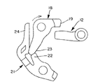
ラッチレバー12の自由端をスプリングの付勢力を受けたアクティブラッチ18の爪19へ対向させる。L字状のアクティブラッチ18は、アクティブレバー20に対し回転自在にピン止めされ、又、スプリングの付勢力を受けたアクティブポール即ちキャンセルレバー21をアクティブレバー20にピン止めさせる。アクティブポール即ちキャンセルレバー21は略V字状のもので、第1のアーム22がアクティブラッチ18の自由端23に対接し、かつ長い第2のアーム24を有す。自由端23と第1のアーム22の対接は、アクティブラッチ18を図2でみて反時計方向への回動を阻止させる。
【0011】
ドアの閉動作終了後、ポールスイッチ25(図1参照)がドアの非完全(ハーフ)閉状態を検知すると、電動モータ(M)が動作し、その出力レバー26を回転させ、アクティブレバー20を図2でみて下向きに移動させる。この結果、アクティブラッチ18の爪19がラッチレバー12の自由端に当接しラッチレバー12がE方向(図2でみて)へ回り、ラッチレバー12と一体のピン2とラッチ1を非完全(ハーフ)ラッチ状態位置から完全(フル)ラッチ状態位置へ自動的に移動させる。
アクティブラッチ18のラッチレバー12への当接時、アクティブラッチ18の自由端23がアクティブポール即ちキャンセルレバー21の第1のアーム22に当接し、アクティブラッチ18の反時計方向(図2でみて)への回動が阻止されているので、ラッチレバー12のE方向への回動が可能となる。尚、アクティブラッチ18の時計方向への回動は自在である。
【0012】
ドアの閉操作中にドアとボデイとの間に服や手荷物のような物を挟んでドアが開状態から非完全(ハーフ)閉状態となった場合、ドアクローザによるドア閉動作をキャンセルさせる必要がある。
物をドアに挟んだりした場合、ハンドルを操作してドアを開操作すると、中間レバー27が、図3でみて、反時計方向へ回動する。このため、オープンレバー13がF方向(図1のB方向に相当)へ回り、図1と関連して説明したドア開動作と同じ動作が得られる。中間レバー27のこの動きは、中間レバー27の自由端28が、アクティブポール21の第2のアーム24に当接し、アクティブポール21を図3に実線で示す位置に移動させる。この結果、アクティブポール21の第1のアーム22とアクティブラッチ18の自由端23との係合が解除され、アクティブラッチ18が自由回転状態となる。
【0013】
このような状態の下で、ポールスイッチ25がドア非完全(ハーフ)閉状態を検知すると、図2と関連して説明した如く、電動モータ(M)がアクティブレバー20とアクティブラッチ18を押下げるが、アクティブポール21の第1のアーム22とアクティブラッチ18の自由端23との係合が解放されているので、爪19がラッチレバー12に当接しても、アクティブラッチ18が自由回転し、ラッチレバー12の回転はない。かくして、ドアの非完全(ハーフ)閉状態から完全(フル)閉状態への移行はなく、しかも、ドアの開操作がなされる。
【0014】
前述した操作の際、ラッチレバー12の自由端が、図4に示す如く、アクティブラッチ18の爪19の下方に位置し、ラッチレバー12の回動又はアクティブポール21を反時計方向に回動させたときアクティブラッチ18の反時計方向への回動を可能にさせる。しかし、キャンセル操作中のドア開により、時には、アクティブラッチ18の自由回動により図5に示す位置関係即ち爪19の上方にラッチレバー12の自由端が位置する異常状態となることがある。この場合、ドア閉動作により、ラッチ1によりラッチレバー12を反時計に回転させ、ラッチレバー12の自由端にアクティブラッチ18の爪19を当接させ、図5でみてアクティブラッチ18を時計方向に自由回転させ、図4の正常状態を得る。
この異常回避は、アクティブラッチ18の、図4と図5でみて、時計方向への回動を自在とさせたことにより得られる。
この異常状態の回避のため、図1、図3に示す如く、ラッチレバー12の自由端であって、アクティブラッチ18の爪部19に当接する側面を傾斜面29とさせる。図5に示す如く、前述のドア閉動作でラッチレバー12が反時計方向へ回動して、アクティブラッチ18を自由回転させるが、この傾斜面29は当接部での両者のすべりと当接ストロークを小さくし、迅速な正常位置へのラッチレバー12の復帰を可能にする。
【図面の簡単な説明】
【図1】ドアロック装置のオープン系の一部を示す斜視図である。
【図2】ドアロック装置のドアクローザの部分を示す斜視図である。
【図3】キャンセル操作を説明するための斜視図である。
【図4】アクティブラッチとラッチレバーとの正常関係を示す図である。
【図5】アクティブラッチとラッチレバーとの異常関係を示す図である。
【図6】ラッチとポールとの関係を示す平面図である。
【符号の説明】
1 ラッチ
5 係合溝
6、7 爪部
8 ポール
9 突部
11 リフトレバー
12 ラッチレバー
13 オープンレバー
17、19 爪
18 アクティブラッチ
20 アクティブレバー
21 アクティブポール(キャンセルレバー)
25 ポールスイッチ
29 傾斜面[0001]
[Industrial application fields]
The present invention relates to a door closer device that automatically closes a door in a non-complete (half) closed state to a full (full) closed state.
[0002]
[Prior art]
The complete (full) closed state of the vehicle side door is obtained by engaging a striker, which is a member on the vehicle side of the vehicle, with a latch that constitutes a part of a door lock device equipped on the side door. As shown in FIG. 6, the latch 1 is rotatable around the
[0003]
The
In the door open (open) state, the
[0004]
In the above-described door closing operation, when the operation force is weak, for example, the
Examples of this type of door closer are disclosed in Japanese Patent Laid-Open Nos. 2-96079 and 6-50045.
[0005]
[Problems to be solved by the invention]
The door closer mechanism has a configuration in which a latch lever that rotates a rotating shaft of a latch is brought into contact with an active latch that is fixed to an active lever that is raised and lowered by an electric motor, and the latch lever is rotated according to the movement of the active latch. Is adopted. When an incomplete (half) closed state of the door is detected, the electric motor operates the active lever, and this movement is transmitted to the latch lever through the active latch, and the latch is incomplete as the latch lever rotates. It is automatically moved from a position corresponding to the (half) closed state (non-complete (half) latched state) to a position corresponding to the door fully (full) closed state (complete (full) latched state).
[0006]
However, sometimes, objects such as clothes and baggage are sandwiched between the door and the body during the door closing operation, and the door is changed from the open state to the incomplete (half) closed state. In this case, it is necessary to cancel the door closing operation by the door closer.
[0007]
Therefore, an object of the present invention is to solve the above-described cancellation reliably.
[0008]
[Means for Solving the Problems]
In the present invention, for the cancel operation described above, an active pawl or cancel lever that restricts the movement of the active latch in one direction is basically interposed between the active latch that can contact the latch lever and the active lever. And adopting a technical means for allowing the cancel lever to release the restriction of the one-way movement of the active latch.
Specifically, the present invention selects a first position where the door can be opened with respect to the vehicle body side member, a second position where the door is not fully closed, and a third position where the door is fully closed. A latch that takes one of the above, a pole that maintains any of the above-mentioned positions of the latch, an electric motor that operates by detecting the incompletely closed state of the door, an active lever that moves along a fixed linear locus by the output of the electric motor, An active latch that is rotatably supported, a cancel lever that is capable of restricting the rotation of the active latch in one direction and is rotatably supported by the active lever, and a free end that is fixed to the latch and faces the active latch and a latch lever, active latch by one-way rotation of active latch is restricted to take latches latch lever third position By the rotation of the cancel lever causes the urchin rotated to provide a latch of the latch lever by regulating the direction of rotation of the active latch is released door closing device for canceling the rotation that takes the third position.
[0009]
DETAILED DESCRIPTION OF THE INVENTION
Please refer to FIG. 1 and FIG. The
[0010]
The free end of the
[0011]
After the door closing operation is completed, when the pole switch 25 (see FIG. 1) detects the door incomplete (half) closed state, the electric motor (M) operates, rotates its output lever 26, and turns the
When the
[0012]
If the door is closed from the open state to the incomplete (half) closed state with an object such as clothes or baggage between the door and the body during the door closing operation, it is necessary to cancel the door closing operation by the door closer is there.
When an object is sandwiched between doors, when the door is opened by operating the handle, the
[0013]
Under such a state, when the
[0014]
In the above-described operation, the free end of the
This abnormality avoidance can be obtained by allowing the
In order to avoid this abnormal state, as shown in FIGS . 1 and 3 , a side surface that is a free end of the
[Brief description of the drawings]
FIG. 1 is a perspective view showing a part of an open system of a door lock device.
FIG. 2 is a perspective view showing a door closer portion of the door lock device.
FIG. 3 is a perspective view for explaining a cancel operation.
FIG. 4 is a diagram showing a normal relationship between an active latch and a latch lever.
FIG. 5 is a diagram showing an abnormal relationship between an active latch and a latch lever.
FIG. 6 is a plan view showing a relationship between a latch and a pole.
[Explanation of symbols]
DESCRIPTION OF SYMBOLS 1
25
Claims (2)
Priority Applications (3)
| Application Number | Priority Date | Filing Date | Title |
|---|---|---|---|
| JP12924896A JP3622336B2 (en) | 1996-04-26 | 1996-04-26 | Door closer equipment |
| US08/842,355 US5951069A (en) | 1996-04-26 | 1997-04-24 | Door closing apparatus |
| DE1997117640 DE19717640B4 (en) | 1996-04-26 | 1997-04-25 | Door locking device |
Applications Claiming Priority (1)
| Application Number | Priority Date | Filing Date | Title |
|---|---|---|---|
| JP12924896A JP3622336B2 (en) | 1996-04-26 | 1996-04-26 | Door closer equipment |
Publications (2)
| Publication Number | Publication Date |
|---|---|
| JPH09291736A JPH09291736A (en) | 1997-11-11 |
| JP3622336B2 true JP3622336B2 (en) | 2005-02-23 |
Family
ID=15004876
Family Applications (1)
| Application Number | Title | Priority Date | Filing Date |
|---|---|---|---|
| JP12924896A Expired - Fee Related JP3622336B2 (en) | 1996-04-26 | 1996-04-26 | Door closer equipment |
Country Status (1)
| Country | Link |
|---|---|
| JP (1) | JP3622336B2 (en) |
Families Citing this family (1)
| Publication number | Priority date | Publication date | Assignee | Title |
|---|---|---|---|---|
| CN108118982A (en) * | 2018-01-05 | 2018-06-05 | 东莞雅音电子科技有限公司 | A kind of motorcar electric door and its automatic door lock device |
-
1996
- 1996-04-26 JP JP12924896A patent/JP3622336B2/en not_active Expired - Fee Related
Also Published As
| Publication number | Publication date |
|---|---|
| JPH09291736A (en) | 1997-11-11 |
Similar Documents
| Publication | Publication Date | Title |
|---|---|---|
| JP3622337B2 (en) | Door closer equipment | |
| US7581767B2 (en) | Door closing device | |
| US6017067A (en) | Latch device for a tailgate of a vehicle | |
| US10895095B2 (en) | Power closure latch assembly with cinch mechanism having ratchet retention function | |
| US10626640B2 (en) | Vehicle door operation device | |
| US6371538B1 (en) | Vehicle door latch device with block type anti-theft mechanism | |
| US8844984B2 (en) | Door lock device | |
| KR100236695B1 (en) | Slide door automatic open/colse device for a vehicle | |
| KR100290201B1 (en) | Power lock for vehicle door with safety device | |
| US20050200137A1 (en) | Latch apparatus and method | |
| JPH0557688B2 (en) | ||
| JP3810280B2 (en) | Latch device for vehicle tailgate | |
| EP1121503B8 (en) | Door latch | |
| JPH10272925A (en) | Automotive door lock half-latch detection device | |
| US5951069A (en) | Door closing apparatus | |
| US11299918B2 (en) | Vehicle door opening/closing device | |
| JP3622335B2 (en) | Door closer equipment | |
| JP3622336B2 (en) | Door closer equipment | |
| EP1179108B1 (en) | Latch | |
| JP4448870B2 (en) | Relay operation device for vehicle door latch | |
| EP1081317A1 (en) | Door lock device with automatic door closing mechanism | |
| JP2004176415A (en) | Door latch device | |
| JP3880846B2 (en) | Latch device for vehicle tailgate | |
| JP3728790B2 (en) | Door lock system | |
| JP2005016096A (en) | Automatic door closure |
Legal Events
| Date | Code | Title | Description |
|---|---|---|---|
| A977 | Report on retrieval |
Free format text: JAPANESE INTERMEDIATE CODE: A971007 Effective date: 20040622 |
|
| A131 | Notification of reasons for refusal |
Free format text: JAPANESE INTERMEDIATE CODE: A131 Effective date: 20040727 |
|
| A521 | Written amendment |
Free format text: JAPANESE INTERMEDIATE CODE: A523 Effective date: 20040909 |
|
| TRDD | Decision of grant or rejection written | ||
| A01 | Written decision to grant a patent or to grant a registration (utility model) |
Free format text: JAPANESE INTERMEDIATE CODE: A01 Effective date: 20041102 |
|
| A61 | First payment of annual fees (during grant procedure) |
Free format text: JAPANESE INTERMEDIATE CODE: A61 Effective date: 20041115 |
|
| FPAY | Renewal fee payment (event date is renewal date of database) |
Free format text: PAYMENT UNTIL: 20081203 Year of fee payment: 4 |
|
| FPAY | Renewal fee payment (event date is renewal date of database) |
Free format text: PAYMENT UNTIL: 20091203 Year of fee payment: 5 |
|
| FPAY | Renewal fee payment (event date is renewal date of database) |
Free format text: PAYMENT UNTIL: 20101203 Year of fee payment: 6 |
|
| FPAY | Renewal fee payment (event date is renewal date of database) |
Free format text: PAYMENT UNTIL: 20101203 Year of fee payment: 6 |
|
| FPAY | Renewal fee payment (event date is renewal date of database) |
Free format text: PAYMENT UNTIL: 20111203 Year of fee payment: 7 |
|
| FPAY | Renewal fee payment (event date is renewal date of database) |
Free format text: PAYMENT UNTIL: 20121203 Year of fee payment: 8 |
|
| FPAY | Renewal fee payment (event date is renewal date of database) |
Free format text: PAYMENT UNTIL: 20121203 Year of fee payment: 8 |
|
| FPAY | Renewal fee payment (event date is renewal date of database) |
Free format text: PAYMENT UNTIL: 20131203 Year of fee payment: 9 |
|
| LAPS | Cancellation because of no payment of annual fees |