JP3620848B2 - Anti-vibration of shadow mask for color CRT - Google Patents
Anti-vibration of shadow mask for color CRT Download PDFInfo
- Publication number
- JP3620848B2 JP3620848B2 JP51281795A JP51281795A JP3620848B2 JP 3620848 B2 JP3620848 B2 JP 3620848B2 JP 51281795 A JP51281795 A JP 51281795A JP 51281795 A JP51281795 A JP 51281795A JP 3620848 B2 JP3620848 B2 JP 3620848B2
- Authority
- JP
- Japan
- Prior art keywords
- shadow mask
- sheet
- vibration
- screen
- coating
- Prior art date
- Legal status (The legal status is an assumption and is not a legal conclusion. Google has not performed a legal analysis and makes no representation as to the accuracy of the status listed.)
- Expired - Fee Related
Links
Images


Classifications
-
- H—ELECTRICITY
- H01—ELECTRIC ELEMENTS
- H01J—ELECTRIC DISCHARGE TUBES OR DISCHARGE LAMPS
- H01J29/00—Details of cathode-ray tubes or of electron-beam tubes of the types covered by group H01J31/00
- H01J29/02—Electrodes; Screens; Mounting, supporting, spacing or insulating thereof
- H01J29/06—Screens for shielding; Masks interposed in the electron stream
- H01J29/07—Shadow masks for colour television tubes
-
- H—ELECTRICITY
- H01—ELECTRIC ELEMENTS
- H01J—ELECTRIC DISCHARGE TUBES OR DISCHARGE LAMPS
- H01J2229/00—Details of cathode ray tubes or electron beam tubes
- H01J2229/07—Shadow masks
- H01J2229/0727—Aperture plate
- H01J2229/0738—Mitigating undesirable mechanical effects
- H01J2229/0744—Vibrations
-
- H—ELECTRICITY
- H01—ELECTRIC ELEMENTS
- H01J—ELECTRIC DISCHARGE TUBES OR DISCHARGE LAMPS
- H01J2229/00—Details of cathode ray tubes or electron beam tubes
- H01J2229/07—Shadow masks
- H01J2229/0727—Aperture plate
- H01J2229/0777—Coatings
Landscapes
- Electrodes For Cathode-Ray Tubes (AREA)
Description
発明の分野
この発明は、画面上の蛍光体素子に入射する電子ビームを制御するためのシャドーマスクを有するカラー陰極線管(以下、カラーCRTと略記する)に関し、特に、画像のカラー純度を改善するためにシャドーマスクの振動を抑制してシャドーマスクの電子ビーム通過孔と蛍光体素子との位置関係の整合を維持する防振構造に関する。
発明の背景
カラーCRTに現在使われているシャドーマスクという技術思想の歴史は1949年まで溯る。マスクパターンはこの間ドット、ストリップ及びスロットなどいろいろな形を取ったが、作用の基本理論は変わっていない。即ち、CRTのネックに取りつけられた偏向ヨークによって集束されて陰極線ルミネセンス・スクリーン上を水平方向及び垂直方向に走査される3つの別々に変調される電子ビームを使用する。表示パネルスクリーンは、ステンシルとしてマスクを使って写真製版により作られる。シャドーマスク・カラーCRTは、輝度、コントラストが極めて優れていて技術が成熟しているために40年以上にわたって消費者市場を支配してきた。
シャドーマスクは、CRTの画面上に写真付着された(photo−deposited)赤、青及び緑の3色で一組の発光蛍光体の規則的パターンから成るターゲット又はスクリーンと組み合わされて使用する。シャドーマスクは、多孔性であり、ターゲットから所定の距離を置いて配置されていて、そのビーム通過孔のパターンによって、個々の発光蛍光体の中から選択された発光蛍光体を除いて他の全ての発光体をCRTのネックに位置する対応する電子ビーム放射源から遮蔽する。マスクのビーム通過孔と画面の発光蛍光体付着物との正確な位置の整合は、画像の高度のカラー純度を得るために不可欠である。マスクの孔と蛍光体付着物との位置の不整合は、時には不均一な電子ビーム加熱とマスクの膨張とに起因するマスクの『膨らみ(doming)』により発生する。従来技術は、例えば、米国特許第4,629,932号、同第4,656,388号、同第4,665,338号、同第4,716,333号、同第4,734,615号及び同第5,028,836号に開示されているような、シャドーマスクの膨らみを補正するための種々の方法を含んでいる。シャドーマスクの孔と画面の蛍光体付着物との位置の整合を精密に維持することは、大きな張力で引っ張られた状態に保たれる平らなシャドーマスクを含有する高精細度テレビジョン(HDTV)受像機においてはより重要であるが、より困難である。
シャドーマスクの孔と画面の蛍光体付着物との位置不整合は、シャドーマスクの振動からも生じる。シャドーマスクの振動は、典型的には、画面との衝突や、或いはステレオ受信能力を備えたテレビジョン受像機において高品質の音声信号により作られる大強度の音波などの外来の因子によって引き起こされる。シャドーマスクの振動は、高性能カラーモニターやハイエンド(high−end)大画面テレビジョン受像機などに採用されている、曲率が小さくてピッチの細かい(単位面積当たりのビーム通過孔の数が多い)シャドーマスクの場合には一層厳しくなる。特に低い振動数で振動しやすい、弾性率が小さくて耐力の大きな材料が多用されるようになってきているので、特にインバールから成るマスクの場合、シャドーマスクの防振が重要である。アルミニウムキルド(AK)鋼から成るような、もっと大きな弾性率を有するマスクでも、振動を示す。インバールは熱膨張率の小さな鉄・ニッケル合金から成るが、AK鋼は、固化の過程における酸素と炭素の反応を最小にするために溶融状態のときに強い脱酸剤(アルミニウムなど)が加えられた鋼である。また、シャドーマスクの振動は、シャドーマスク上のグラファイトなどのコーティングが剥がれたり微小な薄片が脱落したりする原因となることがある。シャドーマスクへの薄片の付着は、電子孔を塞いで、蛍光体スクリーン上の画像の特性に悪影響を与えることがある。電子銃に緩やかに付着している薄片は、電極間に火花を生じさせて高電圧に耐える能力を制限したり画像の質を低下させる原因となったりすることがある。
本発明は、画像のカラー純度を改善するためにマスクの振動を制止するカラーCRT用のシャドーマスク防振手段を提供することによって従来技術の前述したような制限に対処する。
本発明の目的と概要
従って、本発明の目的は、画像のカラー純度を改善するためにカラーCRTのシャドーマスクの振動を減衰させることである。
本発明の他の目的は、画像のカラー純度を改善するために、シャドーマスク構造の弾性率を高めることにより、例えばインバールから成るシャドーマスクなどの、カラーCRTのシャドーマスクの弾性率の低さを補償し、これにより特に低振動数でのシャドーマスクの振動を減衰させて、シャドーマスクの孔とCRTの画面上の蛍光体付着物との位置の整合を維持することである。
本発明の他の目的は、特にCRTの起動後にシャドーマスクを通過する電子ビームに対するシャドーマスク構造のカラー選択作用の質を低下させずにカラーCRTにおける金属シャドーマスク構造の弾性率を増大させることである。
互いに離隔した複数の蛍光体付着物を内面に有する画面を有するカラー陰極線管(CRT)に用いられるシャドーマスク構造によって、本発明の上記の目的は達成され、従来技術の欠点は解消される。このシャドーマスク構造は、その複数の蛍光体付着物の中の選択されたものへの複数の電子ビームの入射を限定する。このシャドーマスク構造は、対向する第1及び第2の面と、互いに離隔した複数の電子ビーム通過孔と、E1の弾性率とを有する金属の薄いシート状部材と、このシート状部材の少なくとも一方の面において前記の孔の周りに位置していてE2の弾性率を有する、このシート状部材の振動を減衰させる硬いコーティングとから成り、E2>E1である。硬いコーティングはガラスベースのフリット又は重金属から成り且つシート状部材の面の上に互いに離隔した複数のほぼ真っ直ぐに延びたバンドとして配置される。
【図面の簡単な説明】
付属の請求の範囲の各項は、発明の新規な特徴事項を述べている。しかし、発明自体と、他の目的及び利点とは、添付図面と関連させて好ましい実施例に関する以下の詳しい記述を参照することにより、良く理解できるものである。図面の幾つかの図において、同じ参照文字は同じ要素を特定している。
図1は、本発明のシャドーマスク防振構造を有するカラーCRTの断面図である。
図1a、図1b、及び図1cは、本発明の原理による防振構造を有するシャドーマスク構造の種々の実施例の部分断面図である。
図2は、本発明のシャドーマスク構造の弾性率(ヤング率)を従来技術のシャドーマスクの弾性率と比較するグラフである。
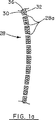
図3は、本発明の他の実施例による防振構造を有するシャドーマスク構造の平面図である。
好ましい実施例の詳細な説明
図1を参照すると、本発明の原理によるシャドーマスク防振構造を有するカラーCRT10の断面図が示されている。CRT10は、前部の画面又は表示スクリーン12と、後部のネック部16と、中間のファンネル部14とを有する密閉されたガラス管26を包含する。ガラス画面12の内面には蛍光体スクリーン18が配置されており、このスクリーンは、電子ビームが入射したときに光を発して画面12の上に画像を生ぜしめる複数の離散した蛍光体の付着物又は素子を包含する。CRTのガラス管26のネック部16には、複数の電子ビーム24を蛍光体スクリーン18に向けるために典型的には列形に配列される複数の電子銃22が設けられている。電子ビーム24は、簡単のために図には示されていない磁性偏向ヨークによって蛍光体スクリーン18の上を垂直方向に且つ水平方向に一斉に偏向される。蛍光体スクリーン18から離隔してシャドーマスク組立体28が配置されており、このシャドーマスク組立体は、互いに離隔した電子ビーム通過孔28aと、周囲のスカート部28bとを包含する。シャドーマスクのスカート部28bは、シャドーマスクの周囲のシャドーマスク取付け具34に固着されている。シャドーマスク取付け具34は、CRTのガラス管26の内面に取りつけられており、簡単のために図示されていないマスク取付けフレーム及び取付けスプリングなどの在来の取付け位置決め構造体を包含することが出来る。シャドーマスク取付け具34はCRTのガラス管26の内面に取りつけることのできるものであり、溶接物やガラスベースのフリットなどの在来の手段によりシャドーマスク組立体28を取付け具に取りつけることが出来る。
本発明に従って、図1aの部分断面図に詳細に示されているように、シャドーマスク組立体28は、内側の防振コーティング又は層30と、外側の防振コーティング32と、その内側及び外側のコーティングの中間に位置するフォイル・シャドーマスク36とを含む。内側及び外側の防振コーティング30、32は、フォイル・シャドーマスク36のそれより大きな弾性率を有する材料から成る。インバールの場合、フォイル・シャドーマスク36は比較的に小さな弾性率と大きな耐力とを有する。その結果として、特に、平らな、或いは比較的に平らな画面と、単位面積当りに多数のビーム通過孔とを有する(精細ピッチ)CRTに搭載されたときには、インバール製のフォイル・シャドーマスクは振動に対して非常に敏感となる。この場合、シャドーマスクの孔28aと、蛍光体スクリーン18の蛍光体の付着物又は素子との位置の整合又は整列を維持するためにシャドーマスクの防振が不可欠である。内側及び外側の防振コーティング30、32は、フォイル・シャドーマスク36のそれより大きな弾性率を有する材料から成り、好ましい実施例においてはガラスベースのフリット又はタングステンやモリブデン等の重金属から成る。内側及び外側の防振コーティング30、32は、ノズルによる吹きつけ又は真空蒸着によってフォイル・シャドーマスク36に付けることのできるものである。振動は表面現象であって、内側及び外側の防振コーティング30、32は、特に低振動数のフォイル・シャドーマスク36の振動を吸収する。内側及び外側の防振コーティング30、32に微小粒子を採用することによって、フォイル・シャドーマスク36の孔28aは、このコーティングが付けられた後も開いたままとなる。図1の実施例に示されているように、内側及び外側の防振コーティング30、32はフォイル・シャドーマスク36の両面全体にわたって付けられている。マスクのビーム通過孔28aが塞がるのを防止するために、防振コーティングの粒子の大きさは約1ミクロンまでとすることが出来る。
図1bを参照すると、本発明の他の実施例であるシャドーマスク組立体40の部分断面図が示されている。図1bに示されている実施例においては、既に記述したように吹きつけ又は真空蒸着などによってフォイル・シャドーマスク42の外側の面だけに防振コーティング44が付けられている。この場合にも、外側防振コーティング44の中に微小粒子を用いることにより、フォイル・シャドーマスク42の孔42aは開いたままであり、電子ビームの通過を許す。
図1cを参照すると、本発明の別の実施例であるシャドーマスク組立体48が示されている。図1cに示されている実施例においては、内側の防振コーティング52だけがフォイル・シャドーマスク50の内面に付けられている。図1a、図1b及び図1cに示されているそれぞれの実施例において、内側及び外側の防振コーティングはフォイル・シャドーマスクの振動を減衰させるためにシャドーマスク組立体の弾性率を増大させる。
図2を参照すると、本発明のシャドーマスク組立体と比較して在来のシャドーマスク材料についての歪みと応力の変化がグラフで示されている。図2に示されている第1の曲線54の直線部分の勾配は、従来のシャドーマスクについての弾性率即ちヤング率である。インバールの従来技術シャドーマスクは21×106psi(ポンド/平方インチ)の弾性率を有し、AKシャドーマスクは31×106psiの弾性率を有する。弾性率即ち前記曲線の勾配を増大させることが極めて望ましい。本発明の防振コーティング又はコーティングを用いるシャドーマスク組立体の改善された弾性率が図2に破線の形の曲線56で示されている。フォイル・シャドーマスクのコーティングは、シャドーマスク組立体の全体としての弾性率を増大させながらフォイル・シャドーマスクの振動を吸収し減衰させる。
図3を参照すると、本発明の原理によるシャドーマスク組立58の実施例の立面図が示されている。シャドーマスク組立体58は、その全面にわたって互いに離隔した多数の孔62を有するフォイル・シャドーマスク60を包含するが、簡単のためにフォイル・シャドーマスク60の上部だけにビーム通過孔が図示されている。シャドーマスク組立体58は、第1の上側防振バンド又はストリップ64と第2の下側防振バンド又はストリップ66とを包含する。上側と下側の防振バンド64、66を、前述したようにフォイル・シャドーマスク60の一面又は両面に配置することが出来る。同様に、上側及び下側の防振バンド64、66は、電子ビームの通過を許すためにフォイルの孔62を開いた状態に保つような方法でフォイル・シャドーマスク60に付けられる。上側及び下側の防振バンド64、66は、フォイル・シャドーマスク60の長辺に沿って延在していて、ガラスベースのフリット又は重金属から成ることができ、前述と同じく吹きつけ又は真空蒸着により付けられる。
図3は破線の形でフォイル・シャドーマスク60の短辺に沿って延在している第3及び第4の側部防振バンド68及び70も図示しているが、これらを上記の第1上側防振バンド64及び第2下側防振バンド66と組み合わせて、或いはそれらの代わりに、用いることが出来る。第3及び第4の側部バンド68、70は、フォイル・シャドーマスク60のそれぞれの側端部の近くに位置して、ほぼ平行に配置されている。第3及び第4の側部バンド68、70は、前述した第1上側防振バンド64及び第2下側防振バンド66と同じ組成であることができるとともに、同じ方法でフォイル・シャドーマスク60に付けられることができる。図3に示されている両方の実施例において、平行な、互いに離隔したバンドは、フォイル・シャドーマスク60の振動を減衰させて、そのフォイル孔62と、簡単のために図示されていない蛍光体スクリーンの蛍光体素子との位置の整合を維持する。一実施例において、前述のバンドは、幅が0.5インチで、シャドーマスク60の隣接する端部から約1インチ離れている。
カラーCRTに用いられる有孔シャドーマスクの一面又は両面に付けられた防振コーティングを包含するシャドーマスク防振構造を以上に示したが、これはシャドーマスクの振動を減衰させてそのフォイル孔とCRTの画面の蛍光体素子との位置の整合を維持する。電子ビームの通過を許すためにマスクの孔の開いた状態に保つような方法で吹きつけ又は真空蒸着によりフォイル・シャドーマスクの外側面又は内側面、又はその両面に、防振コーティングを付けることが出来る。防振コーティングは、シャドーマスクの短辺又は長辺に沿って延在する複数の互いに離隔したバンド又はストリップの形で付けられる。防振コーティングは、例えばガラスベースのフリットや、或いはタングステン又はモリブデンなどの重金属などの、フォイル・シャドーマスクより大きな弾性率を有する材料から成る。
本発明の特別の実施例を図示し説明したが、広範な面において本発明から逸脱することなく変更や修正をし得ることが当業者にとっては明白であろう。従って、付属の請求項の狙いは、本発明の範囲に属するような変更や修正を全て網羅することである。以上の明細書と添付図面とに記載されている事項は、限定事項としてではなくて例として提示されたものである。本発明の実際の範囲は、従来技術に基づいて正当に見て以下の請求項において定義される。 Field of the Invention The present invention relates to a color cathode ray tube (hereinafter abbreviated as a color CRT) having a shadow mask for controlling an electron beam incident on a phosphor element on a screen, and in particular, the color of an image. The present invention relates to an anti-vibration structure that suppresses vibration of a shadow mask to improve the purity and maintains alignment of the positional relationship between an electron beam passage hole of the shadow mask and a phosphor element.
Background of the invention The history of the technical idea of shadow masks currently used in color CRTs goes back to 1949. The mask pattern took various forms such as dots, strips and slots during this period, but the basic theory of action has not changed. That is, it uses three separately modulated electron beams that are focused by a deflection yoke attached to the neck of the CRT and scanned horizontally and vertically on the cathodoluminescence screen. The display panel screen is made by photoengraving using a mask as a stencil. Shadow mask color CRTs have dominated the consumer market for over 40 years due to their excellent brightness, contrast and mature technology.
The shadow mask is used in combination with a target or screen consisting of a regular pattern of a set of luminescent phosphors in three colors photo-deposited red, blue and green on a CRT screen. The shadow mask is porous and is placed at a predetermined distance from the target, and the pattern of its beam passage holes allows all other phosphors to be selected except for the individual phosphors. Are shielded from the corresponding electron beam radiation source located at the neck of the CRT. Accurate positional alignment between the mask beam passage aperture and the luminescent phosphor deposits on the screen is essential to obtain a high color purity of the image. Misalignment between the mask holes and the phosphor deposits is sometimes caused by mask “doming” due to non-uniform electron beam heating and mask expansion. The prior art corrects the bulge of the shadow mask, as disclosed in, for example, U.S. Pat. It includes various ways to do this. Maintaining precise alignment between the shadow mask holes and the phosphor deposits on the screen is a high-definition television (HDTV) that contains a flat shadow mask that remains pulled under high tension. More important in the receiver, but more difficult.
Misalignment between the shadow mask holes and the phosphor deposits on the screen also results from the shadow mask vibration. Shade mask vibrations are typically caused by extraneous factors such as collisions with the screen or high intensity sound waves produced by high quality audio signals in television receivers with stereo reception capabilities. Shade mask vibration is used in high-performance color monitors and high-end large-screen television receivers, etc., with low curvature and fine pitch (high number of beam passage holes per unit area) In the case of a shadow mask, it becomes more severe. In particular, in the case of a mask made of Invar, it is important to prevent the shadow mask from being vibrated, since a material having a low elastic modulus and a large proof stress, which is likely to vibrate at a low frequency, has been widely used. Even masks with a higher modulus of elasticity, such as made of aluminum killed (AK) steel, exhibit vibration. Invar is made of an iron-nickel alloy with a low coefficient of thermal expansion, but AK steel is added with a strong deoxidizer (such as aluminum) when molten to minimize the reaction between oxygen and carbon during the solidification process. Steel. In addition, the vibration of the shadow mask may cause a coating such as graphite on the shadow mask to peel off or a minute flake to fall off. The attachment of flakes to the shadow mask can block the electron holes and adversely affect the properties of the image on the phosphor screen. The flakes that are gently attached to the electron gun can cause sparks between the electrodes, limiting the ability to withstand high voltages and reducing image quality.
The present invention addresses the aforementioned limitations of the prior art by providing a shadow mask anti-vibration means for a color CRT that suppresses mask vibration to improve the color purity of the image.
Objects and overview of the present invention Accordingly, it is an object of the present invention to attenuate the vibration of the shadow mask of a color CRT to improve the color purity of the image.
Another object of the present invention is to increase the elastic modulus of the shadow mask structure in order to improve the color purity of the image, thereby reducing the low elastic modulus of the shadow mask of the color CRT, such as a shadow mask made of Invar. Compensation, thereby attenuating the vibration of the shadow mask, particularly at low frequencies, to maintain alignment of the shadow mask holes with the phosphor deposits on the CRT screen.
Another object of the present invention is to increase the elastic modulus of the metal shadow mask structure in the color CRT without degrading the quality of the color selection effect of the shadow mask structure particularly on the electron beam passing through the shadow mask after the CRT is activated. is there.
The above-mentioned object of the present invention is achieved by the shadow mask structure used in a color cathode ray tube (CRT) having a screen having a plurality of phosphor deposits separated from each other on the inner surface, and the disadvantages of the prior art are eliminated. This shadow mask structure limits the incidence of multiple electron beams on selected ones of the multiple phosphor deposits. The shadow mask structure includes a metal thin sheet-like member having first and second surfaces facing each other, a plurality of electron beam passage holes spaced apart from each other, and an elastic modulus of E 1 , and at least the sheet-like member. in one side be located around the hole having a modulus of elasticity of E 2, it consists of a hard coating to damp the vibration of the sheet-like member, a E 2> E 1. The hard coating consists of a glass-based frit or heavy metal and is arranged as a plurality of substantially straight bands spaced from one another on the surface of the sheet-like member.
[Brief description of the drawings]
Each section of the appended claims describes novel features of the invention. However, the invention itself, and other objects and advantages, may be better understood by referring to the following detailed description of the preferred embodiment in connection with the accompanying drawings. In the several figures of the drawings, the same reference characters identify the same elements.
FIG. 1 is a cross-sectional view of a color CRT having a shadow mask anti-vibration structure of the present invention.
FIGS. 1a, 1b, and 1c are partial cross-sectional views of various embodiments of a shadow mask structure having an anti-vibration structure according to the principles of the present invention.
FIG. 2 is a graph comparing the elastic modulus (Young's modulus) of the shadow mask structure of the present invention with that of a conventional shadow mask.
FIG. 3 is a plan view of a shadow mask structure having an anti-vibration structure according to another embodiment of the present invention.
Detailed Description of the Preferred Embodiment Referring to Figure 1, there is shown a cross-sectional view of a
In accordance with the present invention, as shown in detail in the partial cross-sectional view of FIG. 1a, the
Referring to FIG. 1b, there is shown a partial cross-sectional view of another embodiment of the
Referring to FIG. 1c, another embodiment of the present invention, a
Referring to FIG. 2, there is a graphical representation of strain and stress changes for a conventional shadow mask material compared to the shadow mask assembly of the present invention. The slope of the straight portion of the
Referring to FIG. 3, an elevational view of an embodiment of a shadow mask assembly 58 according to the principles of the present invention is shown. The shadow mask assembly 58 includes a
FIG. 3 also shows third and fourth side
A shadow mask anti-vibration structure including an anti-vibration coating on one or both sides of a perforated shadow mask used in color CRTs has been shown above, which attenuates the shadow mask's vibration and reduces its foil hole and CRT. The position alignment of the screen with the phosphor element is maintained. An anti-vibration coating may be applied to the outer or inner surface of the foil / shadow mask or both by spraying or vacuum deposition in a manner that keeps the mask aperture open to allow the passage of the electron beam. I can do it. The anti-vibration coating is applied in the form of a plurality of spaced bands or strips extending along the short or long side of the shadow mask. The anti-vibration coating is made of a material having a greater elastic modulus than the foil and shadow mask, such as a glass-based frit or a heavy metal such as tungsten or molybdenum.
While particular embodiments of the present invention have been illustrated and described, it would be obvious to those skilled in the art that changes and modifications can be made without departing from the invention in a broad aspect. Accordingly, the scope of the appended claims is to cover all changes and modifications as falling within the scope of the invention. The matter set forth in the foregoing specification and accompanying drawings is offered by way of illustration and not as a limitation. The actual scope of the invention is defined in the following claims, as viewed reasonably on the basis of the prior art.
Claims (8)
対向する第1及び第2の面と、互いに離隔した複数の電子ビーム通過孔と、E1の弾性率とを有する金属の薄いシート部材と、
前記シート状部材の少なくとも一方の面において前記の孔の周りに位置していてE2の弾性率を有する、前記シート状部材の振動を減衰させる硬いコーティングとから成り、E2>E1であり、前記の硬いコーティングはガラスベースのフリット又は重金属から成り且つ前記シート状部材の面の上に互いに離隔した複数のほぼ真っ直ぐに延びたバンドとして配置されていることを特徴とするシャドーマスク構造。A plurality of electron beams used for a color cathode ray tube (CRT) having a screen with a plurality of light emitting phosphor deposits spaced apart from each other on the inner surface thereof, and a selected phosphor deposit among the phosphor deposits A shadow mask structure for limiting the incidence of
A thin metal sheet member having first and second surfaces facing each other, a plurality of electron beam passage holes spaced apart from each other, and an elastic modulus of E 1 ;
Wherein at least one surface of the sheet-like member be located around the hole having a modulus of elasticity of E 2, consists of a hard coating to damp the vibrations of the sheet-like member, it is E 2> E 1 The shadow mask structure is characterized in that the hard coating is made of glass-based frit or heavy metal and is arranged on the surface of the sheet-like member as a plurality of substantially straight bands spaced from each other.
前記シャドーマスクの少なくとも一つの面において、エネルギーを吸収するコーティングが孔の周りに設けられており、前記シャドーマスクの剛性を高めて前記シャドーマスクの振動を減衰させるために前記エネルギー吸収コーティングはガラスベースのフリット又は重金属から成っていて前記シャドーマスクのそれより大きな弾性率を有し、前記コーティングは前記シャドーマスクの少な くとも一つの面の上に互いに離隔した複数のほぼ真っ直ぐに延びたバンドとして配置されていることを特徴とするカラー陰極線管。In a color cathode ray tube (CRT) having a glass screen with a phosphor screen on the inner surface and an electron gun for directing a plurality of electron beams to the phosphor screen to form an image on the screen, the CRT is: Including a shadow mask having a plurality of holes spaced apart from each other to allow the incidence of each of the electron beams on selected phosphor deposits of the phosphor screen, the shadow mask vibrating in the shadow mask Has a small elastic modulus that gives rise to
In at least one face of the shadow mask, an energy absorbing coating is provided around the hole, and the energy absorbing coating is glass-based to increase the rigidity of the shadow mask and damp vibration of the shadow mask. frit or consist of heavy metals has a larger elastic modulus than that of the shadow mask, the coating as a substantially straight extending bands plurality of spaced from each other on a least one surface of said shadow mask A color cathode ray tube characterized by being arranged.
Applications Claiming Priority (3)
| Application Number | Priority Date | Filing Date | Title |
|---|---|---|---|
| US08/141,999 | 1993-10-28 | ||
| US08/141,999 US5451833A (en) | 1993-10-28 | 1993-10-28 | Shadow mask damping for color CRT |
| PCT/US1994/012313 WO1995012209A1 (en) | 1993-10-28 | 1994-10-27 | Shadow mask damping for color crt |
Publications (2)
| Publication Number | Publication Date |
|---|---|
| JPH08505264A JPH08505264A (en) | 1996-06-04 |
| JP3620848B2 true JP3620848B2 (en) | 2005-02-16 |
Family
ID=22498154
Family Applications (1)
| Application Number | Title | Priority Date | Filing Date |
|---|---|---|---|
| JP51281795A Expired - Fee Related JP3620848B2 (en) | 1993-10-28 | 1994-10-27 | Anti-vibration of shadow mask for color CRT |
Country Status (6)
| Country | Link |
|---|---|
| US (1) | US5451833A (en) |
| EP (1) | EP0682807B1 (en) |
| JP (1) | JP3620848B2 (en) |
| KR (1) | KR100318337B1 (en) |
| DE (1) | DE69415302T2 (en) |
| WO (1) | WO1995012209A1 (en) |
Families Citing this family (12)
| Publication number | Priority date | Publication date | Assignee | Title |
|---|---|---|---|---|
| KR100393656B1 (en) * | 1995-11-08 | 2003-10-10 | 삼성에스디아이 주식회사 | Shadow mask for color cathode ray tube and method for manufacturing the same |
| JP3189765B2 (en) * | 1997-10-20 | 2001-07-16 | ソニー株式会社 | Color cathode ray tube and aperture grill |
| KR100269367B1 (en) * | 1997-11-12 | 2000-10-16 | 구자홍 | Device for damping shadow mask in flat braun tube |
| KR100241597B1 (en) * | 1997-12-01 | 2000-02-01 | 손욱 | Panel assembly for cathode ray tube |
| KR100255273B1 (en) * | 1998-01-22 | 2000-05-01 | 손욱 | A shadow mask and a method of preparing the same |
| US6144148A (en) * | 1998-08-10 | 2000-11-07 | Chunghwa Picture Tubes, Ltd. | Thermal expansion for color CRT |
| IT1313721B1 (en) * | 1999-09-24 | 2002-09-17 | Videocolor Spa | COLOR SELECTION MASK FOR TUBE WITH DEAD-BEAMS |
| KR100669449B1 (en) | 2000-01-31 | 2007-01-15 | 삼성에스디아이 주식회사 | Tension mask for cathode ray tube |
| KR100669672B1 (en) | 2000-02-11 | 2007-01-16 | 삼성에스디아이 주식회사 | Tension mask and frame asseambly for color cathode ray tube |
| KR100331818B1 (en) * | 2000-04-11 | 2002-04-09 | 구자홍 | shadow mask for cathode ray tube |
| KR100351858B1 (en) * | 2000-10-17 | 2002-09-11 | 엘지전자주식회사 | Structure for damping vibration of shadow mask in flat cathode ray tube |
| US6710531B2 (en) * | 2001-12-21 | 2004-03-23 | Thomson Licensing S.A. | CRT having a shadow mask vibration damper |
Family Cites Families (23)
| Publication number | Priority date | Publication date | Assignee | Title |
|---|---|---|---|---|
| US3973965A (en) * | 1972-05-30 | 1976-08-10 | Tokyo Shibaura Electric Co., Ltd. | Making shadow mask with slit-shaped apertures for CRT |
| DE3125075C2 (en) * | 1980-07-16 | 1987-01-15 | N.V. Philips' Gloeilampenfabrieken, Eindhoven | Color picture tube |
| US4631439A (en) * | 1983-02-25 | 1986-12-23 | Rca Corporation | Cathode-ray tube having cylindrical faceplate and shadow mask with minor axis curvatures |
| JPS59189538A (en) * | 1983-04-13 | 1984-10-27 | Toshiba Corp | Color picture tube |
| JPS59211942A (en) * | 1983-05-17 | 1984-11-30 | Toshiba Corp | Member for color picture tube |
| JPH0738295B2 (en) * | 1983-08-16 | 1995-04-26 | 株式会社東芝 | Color picture tube |
| JPS6091534A (en) * | 1983-10-25 | 1985-05-22 | Toshiba Corp | Manufacture of color picture tube |
| DE3476839D1 (en) * | 1983-11-18 | 1989-03-30 | Toshiba Kk | Color picture tube |
| NL8400806A (en) * | 1984-03-14 | 1985-10-01 | Philips Nv | COLOR IMAGE TUBE. |
| JPS61203538A (en) * | 1985-03-05 | 1986-09-09 | Toshiba Corp | Color cathode-ray tube |
| JPS61273835A (en) * | 1985-05-29 | 1986-12-04 | Mitsubishi Electric Corp | Manufacture of shadowmask |
| US4734615A (en) * | 1985-07-17 | 1988-03-29 | Kabushiki Kaisha Toshiba | Color cathode ray tube |
| JPS6282631A (en) * | 1985-10-08 | 1987-04-16 | Hitachi Metals Ltd | Shadowmask member |
| JPS6282630A (en) * | 1985-10-08 | 1987-04-16 | Hitachi Metals Ltd | Shadowmask member |
| JPS62154524A (en) * | 1985-12-27 | 1987-07-09 | Hitachi Ltd | Manufacture of color cathode-ray tube |
| JPS6364248A (en) * | 1986-09-05 | 1988-03-22 | Hitachi Ltd | Color picture tube |
| JPS6381730A (en) * | 1986-09-26 | 1988-04-12 | Mitsubishi Electric Corp | Surface treating method for shadow mask |
| JPH0275132A (en) * | 1988-09-09 | 1990-03-14 | Hitachi Ltd | Shadow mask type color cathode-ray tube |
| FR2638282B1 (en) * | 1988-10-25 | 1996-04-05 | Videocolor | MASK TUBE FOR VISUALIZATION, ESPECIALLY COLOR TELEVISION |
| JPH0317930A (en) * | 1989-06-13 | 1991-01-25 | Mitsubishi Electric Corp | Manufacture of color cathode-ray tube |
| JPH0320934A (en) * | 1989-06-15 | 1991-01-29 | Mitsubishi Electric Corp | Color cathode-ray tube |
| JPH03208225A (en) * | 1990-01-09 | 1991-09-11 | Mitsubishi Electric Corp | Manufacture of shadow mask |
| JPH0554814A (en) * | 1991-08-26 | 1993-03-05 | Mitsubishi Electric Corp | Shadow mask type color cathode-ray tube |
-
1993
- 1993-10-28 US US08/141,999 patent/US5451833A/en not_active Expired - Lifetime
-
1994
- 1994-10-27 DE DE69415302T patent/DE69415302T2/en not_active Expired - Fee Related
- 1994-10-27 WO PCT/US1994/012313 patent/WO1995012209A1/en active IP Right Grant
- 1994-10-27 JP JP51281795A patent/JP3620848B2/en not_active Expired - Fee Related
- 1994-10-27 KR KR1019950702660A patent/KR100318337B1/en not_active IP Right Cessation
- 1994-10-27 EP EP94932069A patent/EP0682807B1/en not_active Expired - Lifetime
Also Published As
| Publication number | Publication date |
|---|---|
| WO1995012209A1 (en) | 1995-05-04 |
| KR100318337B1 (en) | 2002-08-09 |
| EP0682807A1 (en) | 1995-11-22 |
| DE69415302T2 (en) | 1999-06-10 |
| EP0682807A4 (en) | 1996-09-04 |
| US5451833A (en) | 1995-09-19 |
| KR960700518A (en) | 1996-01-20 |
| DE69415302D1 (en) | 1999-01-28 |
| JPH08505264A (en) | 1996-06-04 |
| EP0682807B1 (en) | 1998-12-16 |
Similar Documents
| Publication | Publication Date | Title |
|---|---|---|
| JP3620848B2 (en) | Anti-vibration of shadow mask for color CRT | |
| WO1995012209B1 (en) | Shadow mask damping for color crt | |
| US5990607A (en) | Shadow mask for color CRT and method for forming same | |
| US6072270A (en) | Shadow mask for color CRT | |
| US5519283A (en) | Internal magnetic shield for a color cathode-ray tube | |
| EP1231624B1 (en) | CRT having a vibration damper for a tension mask | |
| EP1405329B1 (en) | Color cathode ray tube having a detensioning mask frame assembly | |
| JPH11238471A (en) | Cathode-ray tube | |
| EP1306875B1 (en) | Tension mask for a cathode-ray-tube | |
| US6700319B2 (en) | Cathode-ray tube having a tension mask with microphonics control | |
| KR100241597B1 (en) | Panel assembly for cathode ray tube | |
| US6603251B1 (en) | Shadow mask for flat cathode ray tube | |
| KR20010000990A (en) | Vibration reduce device of CRT | |
| KR100464282B1 (en) | The Color Cathode-Ray Tube | |
| JP3235493B2 (en) | Color selection mechanism of cathode ray tube and color cathode ray tube | |
| EP1372181A1 (en) | Vibration absorber device for colour cathode-ray tube | |
| CN1060584C (en) | Cathode-ray tube with shock-proof shadow mask | |
| KR100688901B1 (en) | Structure for preventing howling of shadowmask in cathode-ray tube | |
| KR19990074508A (en) | Mask structure of color CRT | |
| KR20010105493A (en) | Apparatus for thwarting howling in cathode ray tube | |
| US20030048062A1 (en) | Color display tube with improved color selection electrode | |
| KR20020091727A (en) | Vibration reduce structure of shadowmask for color ray tube | |
| KR20000005429U (en) | Stud pins for color cathode ray tubes | |
| KR20040047507A (en) | Shadowmask of Color CRT | |
| KR20010018041A (en) | Tension mask of CRT |
Legal Events
| Date | Code | Title | Description |
|---|---|---|---|
| A131 | Notification of reasons for refusal |
Free format text: JAPANESE INTERMEDIATE CODE: A131 Effective date: 20040413 |
|
| A521 | Written amendment |
Free format text: JAPANESE INTERMEDIATE CODE: A523 Effective date: 20040611 |
|
| A131 | Notification of reasons for refusal |
Free format text: JAPANESE INTERMEDIATE CODE: A131 Effective date: 20040727 |
|
| A521 | Written amendment |
Free format text: JAPANESE INTERMEDIATE CODE: A523 Effective date: 20040803 |
|
| TRDD | Decision of grant or rejection written | ||
| A01 | Written decision to grant a patent or to grant a registration (utility model) |
Free format text: JAPANESE INTERMEDIATE CODE: A01 Effective date: 20041026 |
|
| A61 | First payment of annual fees (during grant procedure) |
Free format text: JAPANESE INTERMEDIATE CODE: A61 Effective date: 20041116 |
|
| R150 | Certificate of patent or registration of utility model |
Free format text: JAPANESE INTERMEDIATE CODE: R150 |
|
| LAPS | Cancellation because of no payment of annual fees |