JP3614625B2 - Management manager computer, recording medium, and computer operation management method - Google Patents
Management manager computer, recording medium, and computer operation management method Download PDFInfo
- Publication number
- JP3614625B2 JP3614625B2 JP29403097A JP29403097A JP3614625B2 JP 3614625 B2 JP3614625 B2 JP 3614625B2 JP 29403097 A JP29403097 A JP 29403097A JP 29403097 A JP29403097 A JP 29403097A JP 3614625 B2 JP3614625 B2 JP 3614625B2
- Authority
- JP
- Japan
- Prior art keywords
- information
- information indicating
- event
- computer
- output
- Prior art date
- Legal status (The legal status is an assumption and is not a legal conclusion. Google has not performed a legal analysis and makes no representation as to the accuracy of the status listed.)
- Expired - Fee Related
Links
Images


Classifications
-
- G—PHYSICS
- G06—COMPUTING; CALCULATING OR COUNTING
- G06F—ELECTRIC DIGITAL DATA PROCESSING
- G06F11/00—Error detection; Error correction; Monitoring
- G06F11/07—Responding to the occurrence of a fault, e.g. fault tolerance
- G06F11/0703—Error or fault processing not based on redundancy, i.e. by taking additional measures to deal with the error or fault not making use of redundancy in operation, in hardware, or in data representation
- G06F11/0766—Error or fault reporting or storing
- G06F11/0769—Readable error formats, e.g. cross-platform generic formats, human understandable formats
-
- G—PHYSICS
- G06—COMPUTING; CALCULATING OR COUNTING
- G06F—ELECTRIC DIGITAL DATA PROCESSING
- G06F11/00—Error detection; Error correction; Monitoring
- G06F11/07—Responding to the occurrence of a fault, e.g. fault tolerance
- G06F11/0703—Error or fault processing not based on redundancy, i.e. by taking additional measures to deal with the error or fault not making use of redundancy in operation, in hardware, or in data representation
- G06F11/0706—Error or fault processing not based on redundancy, i.e. by taking additional measures to deal with the error or fault not making use of redundancy in operation, in hardware, or in data representation the processing taking place on a specific hardware platform or in a specific software environment
- G06F11/0748—Error or fault processing not based on redundancy, i.e. by taking additional measures to deal with the error or fault not making use of redundancy in operation, in hardware, or in data representation the processing taking place on a specific hardware platform or in a specific software environment in a remote unit communicating with a single-box computer node experiencing an error/fault
-
- G—PHYSICS
- G06—COMPUTING; CALCULATING OR COUNTING
- G06F—ELECTRIC DIGITAL DATA PROCESSING
- G06F11/00—Error detection; Error correction; Monitoring
- G06F11/30—Monitoring
- G06F11/3003—Monitoring arrangements specially adapted to the computing system or computing system component being monitored
- G06F11/3017—Monitoring arrangements specially adapted to the computing system or computing system component being monitored where the computing system is implementing multitasking
-
- G—PHYSICS
- G06—COMPUTING; CALCULATING OR COUNTING
- G06F—ELECTRIC DIGITAL DATA PROCESSING
- G06F11/00—Error detection; Error correction; Monitoring
- G06F11/30—Monitoring
- G06F11/3051—Monitoring arrangements for monitoring the configuration of the computing system or of the computing system component, e.g. monitoring the presence of processing resources, peripherals, I/O links, software programs
-
- G—PHYSICS
- G06—COMPUTING; CALCULATING OR COUNTING
- G06F—ELECTRIC DIGITAL DATA PROCESSING
- G06F11/00—Error detection; Error correction; Monitoring
- G06F11/30—Monitoring
- G06F11/3065—Monitoring arrangements determined by the means or processing involved in reporting the monitored data
- G06F11/3068—Monitoring arrangements determined by the means or processing involved in reporting the monitored data where the reporting involves data format conversion
-
- G—PHYSICS
- G06—COMPUTING; CALCULATING OR COUNTING
- G06F—ELECTRIC DIGITAL DATA PROCESSING
- G06F11/00—Error detection; Error correction; Monitoring
- G06F11/30—Monitoring
- G06F11/3065—Monitoring arrangements determined by the means or processing involved in reporting the monitored data
- G06F11/3086—Monitoring arrangements determined by the means or processing involved in reporting the monitored data where the reporting involves the use of self describing data formats, i.e. metadata, markup languages, human readable formats
-
- H—ELECTRICITY
- H04—ELECTRIC COMMUNICATION TECHNIQUE
- H04L—TRANSMISSION OF DIGITAL INFORMATION, e.g. TELEGRAPHIC COMMUNICATION
- H04L41/00—Arrangements for maintenance, administration or management of data switching networks, e.g. of packet switching networks
- H04L41/06—Management of faults, events, alarms or notifications
- H04L41/069—Management of faults, events, alarms or notifications using logs of notifications; Post-processing of notifications
-
- G—PHYSICS
- G06—COMPUTING; CALCULATING OR COUNTING
- G06F—ELECTRIC DIGITAL DATA PROCESSING
- G06F11/00—Error detection; Error correction; Monitoring
- G06F11/30—Monitoring
- G06F11/32—Monitoring with visual or acoustical indication of the functioning of the machine
- G06F11/324—Display of status information
- G06F11/328—Computer systems status display
-
- G—PHYSICS
- G06—COMPUTING; CALCULATING OR COUNTING
- G06F—ELECTRIC DIGITAL DATA PROCESSING
- G06F11/00—Error detection; Error correction; Monitoring
- G06F11/30—Monitoring
- G06F11/34—Recording or statistical evaluation of computer activity, e.g. of down time, of input/output operation ; Recording or statistical evaluation of user activity, e.g. usability assessment
- G06F11/3466—Performance evaluation by tracing or monitoring
- G06F11/3476—Data logging
-
- G—PHYSICS
- G06—COMPUTING; CALCULATING OR COUNTING
- G06F—ELECTRIC DIGITAL DATA PROCESSING
- G06F2201/00—Indexing scheme relating to error detection, to error correction, and to monitoring
- G06F2201/86—Event-based monitoring
-
- H—ELECTRICITY
- H04—ELECTRIC COMMUNICATION TECHNIQUE
- H04L—TRANSMISSION OF DIGITAL INFORMATION, e.g. TELEGRAPHIC COMMUNICATION
- H04L41/00—Arrangements for maintenance, administration or management of data switching networks, e.g. of packet switching networks
- H04L41/04—Network management architectures or arrangements
- H04L41/046—Network management architectures or arrangements comprising network management agents or mobile agents therefor
-
- H—ELECTRICITY
- H04—ELECTRIC COMMUNICATION TECHNIQUE
- H04L—TRANSMISSION OF DIGITAL INFORMATION, e.g. TELEGRAPHIC COMMUNICATION
- H04L41/00—Arrangements for maintenance, administration or management of data switching networks, e.g. of packet switching networks
- H04L41/22—Arrangements for maintenance, administration or management of data switching networks, e.g. of packet switching networks comprising specially adapted graphical user interfaces [GUI]
Landscapes
- Engineering & Computer Science (AREA)
- Theoretical Computer Science (AREA)
- Physics & Mathematics (AREA)
- General Engineering & Computer Science (AREA)
- Quality & Reliability (AREA)
- General Physics & Mathematics (AREA)
- Computing Systems (AREA)
- Computer Hardware Design (AREA)
- Mathematical Physics (AREA)
- Computer Networks & Wireless Communication (AREA)
- Signal Processing (AREA)
- Library & Information Science (AREA)
- Debugging And Monitoring (AREA)
- Multi Processors (AREA)
- Computer And Data Communications (AREA)
Description
【0001】
【発明の属する技術分野】
本発明は、複数の計算機が接続されたネットワークに接続され、これらの計算機を管理する管理マネージャ計算機に係り、特に、管理マネージャ計算機が、各計算機で実行される運用処理を一元的に管理することを可能とする技術に関する。
【0002】
【従来の技術】
従来、複数の計算機がネットワークで接続された計算機システムにおいては、例えば、「JP1自動ジョブ運用管理マニュアル(日立,3020−3−735)」や、「JP1自動オペレーションシステム(日立,3020−3−736)」や、「JP1ネットワーク印刷機能マニュアル(日立,3020−3−737)」に記載されているように、各計算機ごと、または、各計算機で実行される運用処理ごとに、該運用処理の実行予定が定義されるようになっており、また、各運用処理の実行結果は、該運用処理の実行予定を定義するための画面とは別の画面によって表示されるようになっている。
【0003】
なお、各運用処理としては、例えば、計算機の電源投入/切断処理,ジョブの実行処理,実行結果の印刷処理,特定の事象の発生時に実行する処理などが挙げられる。
【0004】
一方、「日経コンピュータ(1996.1.22)」の115頁〜117頁、および、「日経オープンシステム(1997.6(no.51))」の234頁〜239頁では、上述した例も含めて、各運用処理の実行を制御するため専用のプログラムが、個別の製品として提供されていることが紹介されている。
【0005】
【発明が解決しようとする課題】
上述した従来技術は、比較的小規模な計算機システムで必要な運用処理についての定義および実行結果の確認を行う場合には好適であるが、複数の運用処理を組み合わせて実行することが多い大規模な計算機システムにおいては、各運用処理についての定義および実行結果の確認を個別に行う必要があることから、上述した従来技術を適用すると、計算機システムとしてのトータルな管理が困難となる。
【0006】
特に、大規模な計算機システムにおいては、組み合わせて実行される複数の運用処理が複数の計算機に渡る場合も考えられるので、計算機システムとしてのトータルな管理を可能とするために、全ての運用処理についての定義および実行結果の確認を、1台の計算機(管理マネージャ計算機)で行うことを可能とすることが好ましい。
【0007】
しかしながら、全ての運用処理についての定義および実行結果の確認を管理マネージャ計算機で行うようにする場合には、管理マネージャ計算機と各計算機との間で通信を行う必要が生じるので、ネットワークトラフィックについても考慮しなければならなくなる。
【0008】
そこで、本発明の目的は、複数の計算機が接続された計算機システムにおいて、これらの計算機を管理する管理マネージャ計算機が、各計算機で実行される運用処理を一元的に管理することを可能とすることにあり、さらに、このとき、ネットワークに余計な負荷をかけないようにすることにある。
【0009】
【課題を解決するための手段】
上記の目的を達成するために、本発明は、第1の態様として、
複数の計算機が接続されたネットワークに接続され、これらの計算機を管理する管理マネージャ計算機であって、
各計算機から、該計算機で実行された運用処理の実行結果を示すログ情報、および、該運用処理の実行過程で発生したイベントを示すイベント情報を収集する収集手段と、
各計算機で実行されるべき運用処理の実行予定が定義された運用定義情報、並びに、上記収集手段が収集したログ情報およびイベント情報をデータベースに格納する格納手段と、
上記格納手段がデータベースに格納した情報を参照することにより、各計算機に係る運用定義情報と、該運用定義情報によって定義された運用処理のログ情報およびイベント情報とを関連付けて表示する表示手段とを有することを特徴とした管理マネージャ計算機を提供している。
【0010】
また、本発明は、第2の態様として、
複数の計算機が接続されたネットワークに接続され、これらの計算機を管理する管理マネージャ計算機であって、
各計算機から、該計算機で実行された運用処理の実行結果を示すログ情報、および、該運用処理の実行過程で発生したイベントを示すイベント情報を収集する収集手段と、
各計算機で実行されるべき運用処理の実行予定が定義された運用定義情報、並びに、上記収集手段が収集したログ情報およびイベント情報をデータベースに格納する格納手段と、
上記格納手段がデータベースに格納した情報を参照することにより、各計算機について、該計算機に係る運用定義情報によって定義された運用処理の一覧を記述した領域、および、該計算機のログ情報を記述した領域を、同じ画面に表示する表示手段とを有することを特徴とした管理マネージャ計算機を提供している。
【0011】
また、本発明は、第3の態様として、
複数の計算機が接続されたネットワークに接続され、これらの計算機を管理する管理マネージャ計算機であって、
各運用処理の実行予定および各運用処理を実行すべき計算機が定義された運用定義情報を一括して作成する一括定義手段と、
上記一括定義手段が作成した運用定義情報を、各計算機に配布する配布手段と、
各計算機から、該計算機で個別に作成された運用定義情報、および、上記配布手段が配布した運用定義情報から自計算機に係る部分を該計算機が展開した運用定義情報を収集すると共に、該計算機で実行された運用処理の実行結果を示すログ情報、および、該運用処理の実行過程で発生したイベントを示すイベント情報を収集する収集手段と、
上記収集手段が収集した運用定義情報、並びに、上記収集手段が収集したログ情報およびイベント情報をデータベースに格納する格納手段と、
上記格納手段がデータベースに格納した情報を参照することにより、各計算機に係る運用定義情報と、該運用定義情報によって定義された運用処理のログ情報およびイベント情報とを関連付けて表示する表示手段とを有することを特徴とした管理マネージャ計算機を提供している。
【0012】
なお、第3の態様の管理マネージャ計算機に管理される各計算機は、
管理マネージャ計算機から配布された運用定義情報から、自計算機に係る部分の運用定義情報を展開するようにすると共に、自計算機で実行された運用処理のログ情報およびイベント情報を、予め定めた共通の形式に変換するようにすることが好ましい。
【0013】
また、第3の態様において、
上記一括定義手段は、
全ての計算機で実行されるべき運用処理については、全ての計算機である旨を示す予め定めた情報を用いて、該運用処理を実行すべき計算機を定義するようにすることができる。
【0014】
また、第1の態様〜第3の態様のいずれにおいても、
上記収集手段は、
各計算機のログ情報のうちの、予め定めた種類のログ情報については、定期的または予め定めたタイミングで収集し、その他の種類のログ情報については、上記表示手段による表示で必要となったときに収集するようにすることができる。
【0015】
また、第1の態様〜第3の態様のいずれにおいても、
上記表示手段は、
上記収集手段が収集したイベント情報の全部または一部については、収集後ただちに表示するようにすることができる。
【0016】
なお、本明細書においては、「計算機」とは、単に演算を行う装置ではなく、通信処理をはじめとする各種情報処理を行う装置を意味している。
【0017】
【発明の実施の形態】
以下、本発明の実施の形態について図面を参照して説明する。
【0018】
図4に、本実施形態に係る計算機システムの全体構成を示す。図中、401は管理マネージャ計算機、402〜407は管理マネージャ計算機の管理対象となる管理対象計算機、408〜413はネットワークである。
【0019】
本実施形態に係る計算機システムは、管理対象計算機(402〜407)で実行されるべき運用処理の実行予定が定義された運用定義情報を、管理マネージャ計算機(401)が一括して作成することを可能とすると共に、管理対象計算機(402〜407)で実行された運用処理について、その実行結果を示すログ情報およびその実行過程で発生したイベントを示すイベント情報を、管理マネージャ計算機(401)が一括して管理することを可能とするものである。
【0020】
これにより、管理マネージャ計算機(401)は、運用定義情報,ログ情報,イベント情報をデータベース化して蓄積することができるので、これらの情報を必要に応じて参照することが可能となると共に、これらの情報を関連付けた多様な切り口からの表示を行うことが可能となる。
【0021】
図1に、管理対象計算機(402〜407)で実行されるべき運用処理の実行予定が定義された運用定義情報を、管理マネージャ計算機(401)が一括して作成するためのシステム構成を示す。図1では、図4の管理マネージャ計算機(401)と1台の管理対象計算機(402)についてのみ示しているが、他の管理対象計算機(403〜407)も、管理対象計算機(402)と同様である。
【0022】
図1に示すように、管理マネージャ計算機(401)は、管理アプリケーション部(101)と、定義情報管理部(102)と、データベース(103)とを備えて構成されている。
【0023】
管理アプリケーション部(101)は、管理対象計算機(402〜407)で実行されるべき運用処理の実行予定が定義された運用定義情報を作成する一括定義部(104)と、後述する統合管理画面等を表示する統合管理画面表示部(105)とを有している。定義情報管理部(102)は、管理対象計算機(402〜407)に運用定義情報を配布したり、管理対象計算機(402〜407)から運用定義情報を収集したりする定義情報配布・収集部(106)を有し、データベース(103)に運用定義情報を格納したり、データベース(103)に格納されている運用定義情報の検索/参照を行う。
【0024】
また、図1に示すように、管理対象計算機(402〜407)は、ジョブ実行制御部(110),電源制御部(111),印刷実行制御部(112)等の、運用定義情報によって定義された運用処理を実行する運用実行部分と、統合管理エージェント(113)とを備えて構成されている。
【0025】
統合管理エージェント(113)は、管理マネージャ計算機(401)から配布された運用定義情報から、自計算機に係る部分の運用定義情報を展開する定義情報展開部(114)と、自計算機で個別に作成された運用定義情報も含めて、自計算機に係る運用定義情報を管理マネージャ計算機(401)に通知する定義情報通知部(115)とを有している。
【0026】
図2に、管理対象計算機(402〜407)で実行された運用処理のログ情報およびイベント情報を、管理マネージャ計算機(401)が一括して管理するためのシステム構成を示す。図2では、図4の管理マネージャ計算機(401)と1台の管理対象計算機(402)についてのみ示しているが、他の管理対象計算機(403〜407)も、管理対象計算機(402)と同様である。
【0027】
図2に示すように、管理マネージャ計算機(401)は、管理アプリケーション部(101)と、イベント・ログ管理部(201)と、データベース(103)とを備えて構成されている。
【0028】
管理アプリケーション部(101)は、後述する統合管理画面等を表示する統合管理画面表示部(105)を有している。イベント・ログ管理部(201)は、管理対象計算機(402〜407)からイベント情報およびログ情報を収集するイベント・ログ収集部(202)を有し、データベース(103)にイベント情報およびログ情報を格納したり、データベース(103)に格納されているイベント情報およびログ情報の検索/参照を行う。また、イベント・ログ管理部(201)は、リアルタイムに運用管理者等に通知すべきイベント情報については、データベース(103)に格納すると共に、統合管理画面表示部(105)に出力する。
【0029】
また、図2に示すように、管理対象計算機(402〜407)は、ジョブ実行制御部(110),電源制御部(111),印刷実行制御部(112)等の、運用定義情報によって定義された運用処理を実行する運用実行部分と、統合管理エージェント(113)とを備えて構成されている。
【0030】
統合管理エージェント(113)は、自計算機で実行された運用処理のログ情報およびイベント情報を、予め定めた共通の形式に変換する正規化部(210)と、正規化されたログ情報やイベント情報を管理マネージャ計算機(401)に通知するイベント・ログ通知部(211)とを有している。
【0031】
図3に、管理マネージャ計算機(401)および管理対象計算機(402〜407)のハードウェア構成を示す。
【0032】
図3に示すように、各計算機は、中央処理装置(301)と、主記憶装置(302)と、通信回線(303)やローカルエリアネットワーク(304)等のネットワークとの間のデータの入出力を制御するネットワーク制御装置(305)と、ディスク装置(306)およびその入出力を制御するディスク制御装置(307)と、表示装置(308)およびその入出力を制御する表示制御装置(309)とを備えて構成されている。
【0033】
図1および図2の構成ブロックのうち、データベース(103)はディスク装置(306)上に実現され、その他の構成ブロックは、ディスク装置(306)に格納されているプログラムを中央処理装置(301)が主記憶装置(302)上にロードして実行することで実現される。なお、このプログラムは、例えば、CD−ROM等の記録媒体に記録され、図示していないドライバによって読み込まれて、ディスク装置(306)に格納されるようにすることができる。
【0034】
以下、図1のシステム構成における運用定義情報の一括定義および配布の手順について、図6(a)を用いて説明する。
【0035】
図6(a)に示すように、管理マネージャ計算機(401)においては、定義情報管理部(102)が、管理アプリケーション部(101)が有する一括定義部(104)で定義された運用定義情報をデータベース(103)に格納する(ステップ601)。データベース(103)に格納された運用定義情報は、定義情報管理部(102)が有する定義情報配布・収集部(106)によって、予め指定されたタイミングで管理対象計算機(402〜407)に配布される(ステップ602)。
【0036】
運用定義情報が配布された管理対象計算機(402〜407)においては、統合管理エージェント(113)が有する定義情報展開部(114)が、配布された運用定義情報から、自計算機に係る部分の運用定義情報を展開して、ジョブ実行制御部(110),電源制御部(111),印刷実行制御部(112)等の運用実行部分に引き渡し(ステップ603)、運用実行部分は、各々、引き渡された運用定義情報によって定義された運用処理を実行する(ステップ604)。
【0037】
一方、管理マネージャ計算機(401)においては、定義情報管理部(102)が有する定義情報配布・収集部(106)が、管理対象計算機(402〜407)で個別に作成された運用定義情報も含めて、管理対象計算機(402〜407)に係る運用定義情報を、管理対象計算機(402〜407)から収集する(ステップ605)。続いて、定義情報管理部(102)が、収集した運用定義情報をデータベース(103)に格納する(ステップ606)。
【0038】
このようにしてデータベース(103)に格納された運用定義情報は、管理アプリケーション部(101)が有する統合管理画面表示部(105)が、運用管理者等からの参照要求に応じて後述する統合管理画面を表示する際に、定義情報管理部(102)によって検索/参照されることとなる。
【0039】
なお、運用定義情報の収集は、管理マネージャ計算機(401)において、定義情報管理部(102)が有する定義情報配布・収集部(106)が、管理対象計算機(402〜407)に対して定期的に命令を発行することで実現するようにしてもよいし、また、管理対象計算機(402〜407)において、統合管理エージェント(113)が有する定義情報通知部(115)が、予め定めたタイミングで、管理マネージャ計算機(401)に対して自発的に運用定義情報を通知することで実現するようにしてもよい。
【0040】
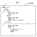
図7に、管理マネージャ計算機(401)が一括定義した運用定義情報の一例を示す。図中、701は運用定義情報である。
【0041】
運用定義情報(701)において、「定義対象(710)」は、定義対象となる管理対象計算機を定義する部分であり、複数の管理対象計算機からなるグループや単一の管理対象計算機を指定することが可能である。なお、図7に示すように、「定義対象(710)」に、予め定めた情報(ここでは、「default」)が指定されている場合は、全ての管理対象計算機が定義対象である旨を示す。
【0042】
「電源制御(711)」は、定義対象となる管理対象計算機の電源投入/切断処理の実行スケジュールや切断方法等を定義する部分であり、「ジョブ実行制御(712)」は、定義対象となる管理対象計算機上のジョブネットおよびジョブネット上のジョブを定義する部分である。図7の例では、「ジョブネットA」は、「ジョブA1」の実行が完了した後、「ジョブA21」と「ジョブA22」とを並列に実行し、これらの両方の実行が完了した時点で「ジョブA3」を実行する旨を定義している。
【0043】
このように、運用管理者等は、管理マネージャ計算機(401)において、各運用処理の実行予定および各運用処理を実行すべき計算機を指定することで、管理対象計算機で実行されるべき運用処理の実行予定が定義された運用定義情報を一括して作成することができる。
【0044】
図8に、図7の運用定義情報(701)が管理対象計算機で展開された後の一例を示す。図8では、図1の管理対象計算機(402〜407)で展開された後の運用定義情報(801〜802)について示しており、これらは、各々、電源制御部(111)およびジョブ実行制御部(110)に引き渡される。
【0045】
次に、図2のシステム構成におけるイベント情報およびログ情報の収集および一括管理の手順について、図6(b)を用いて説明する。
【0046】
図6(b)に示すように、管理対象計算機(402〜407)においては、統合管理エージェント(113)が有する正規化部(210)は、運用実行部分から通知されたイベント情報またはログ情報が、管理マネージャ計算機(401)に通知すべきであると予め指定されている種類の情報である場合には、これを、予め定めた共通の形式に変換し、イベント・ログ通知部(211)によって管理マネージャ計算機(401)に通知する(ステップ610)。
【0047】
イベント情報またはログ情報が通知された管理マネージャ計算機(401)においては、イベント・ログ管理部(201)が有するイベント・ログ収集部(202)が、通知されたイベント情報やログ情報をデータベース(103)に格納する(ステップ611)。特に、イベント情報については、運用過程でリアルタイムに発生する情報であるので、イベント情報が通知された場合には、ただちに、管理アプリケーション部(101)が有する統合管理画面表示部(105)によって、表示装置(308)に表示するようにすることが好ましい(ステップ612)。
【0048】
このようにしてデータベース(103)に格納されたイベント情報およびログ情報は、管理アプリケーション部(101)が有する統合管理画面表示部(105)が、運用管理者等からの参照要求に応じて後述する統合管理画面を表示する際に、定義情報管理部(102)によって検索/参照されることとなる。
【0049】
なお、イベント情報およびログ情報の通知は、リアルタイム性が高いイベント情報(特に、障害を示すイベント情報)については、管理対象計算機(402〜407)において、統合管理エージェント(113)が有するイベント・ログ通知部(211)が、管理マネージャ計算機(401)に対して自発的にイベント情報を通知することで実現することが好ましいが、ログ情報については、管理マネージャ計算機(401)において、イベント・ログ管理部(201)が有するイベント・ログ収集部(202)が、管理対象計算機(402〜407)に対して定期的に命令を発行することで実現するようにしてもよいし、また、管理対象計算機(402〜407)において、統合管理エージェント(113)が有するイベント・ログ通知部(211)が、予め定めたタイミングで、管理マネージャ計算機(401)に対して自発的にログ情報を通知することで実現するようにしてもよい。
【0050】
さて、以下に、管理マネージャ計算機(401)において、管理アプリケーション部(101)が有する統合管理画面表示部(105)が表示する統合管理画面の一例について、図5を用いて説明する。
【0051】
管理マネージャ計算機(401)においては、上述したようにして、運用定義情報,イベント情報,ログ情報がデータベース(103)に格納されるので、運用管理者等は、これらの情報を活用して、計算機システムの運用状況を把握することが可能となる。すなわち、管理マネージャ計算機(401)において、管理アプリケーション部(101)が有する統合管理画面表示部(105)は、運用管理者等から参照が要求された情報を、定義情報管理部(102)によって検索/参照し、検索/参照された情報を用いて統合管理画面を作成し、作成した統合管理画面を表示装置(308)に表示するので、運用管理者等は、表示装置(308)に表示された統合管理画面を見ることで、計算機システムの運用状況を把握することが可能となる。
【0052】
図5において、画面1(501)は、管理マネージャ計算機(401)が管理する管理対象計算機およびそれらのグループを確認するための統合管理画面であり、本例では、4台の管理対象計算機が表示されている。各管理対象計算機は、アイコンとして表示されており、運用管理者等は、例えば、画面1(501)において、「計算機A(502)」をマウスでダブルクリックすることで、画面1(501)から画面2(503)に遷移させることが可能である。
【0053】
また、図5において、画面2(503)は、「計算機A」の運用状況を確認するための統合管理画面であり、「計算機A」について、現在のジョブの実行状況(504)と、「計算機A」上で実行が定義されているジョブネットの一覧(505)と、過去の動作履歴であるログ情報の一覧(506)とが、メッセージ形式で表示されている。運用管理者等は、例えば、画面2(503)において、「ジョブネットA」に関する運用状況を確認したい場合は、ジョブネットの一覧(505)のうちの「ジョブネットA」に関する行をマウスでダブルクリックすることで、画面2(503)から画面3(507)に遷移させることが可能である。
【0054】
また、図5において、画面3(507)は、「計算機A」上の「ジョブネットA」に関する統合管理画面であり、「計算機A」について、「電源投入(509)」,「ジョブネットA(510)の実行」,「実行結果の印刷(511)」という一連の運用処理が定義された運用定義情報を示している。
【0055】
なお、これらの運用処理(509〜511)は、アイコンとして表示されており、各アイコンの表示態様を変更(例えば、色の変更等)することで、「未実行」,「実行中」,「実行の正常終了」,「実行の異常終了」といった各種状態を表すようにすることができる。ここで、統合管理画面表示部(105)は、各アイコンの表示態様を変更する際に、対応する運用処理(509〜511)のその時点での最新のイベント情報を、イベント・ログ管理部(201)が有するイベント・ログ収集部(202)によって収集するようにすることが好ましい。
【0056】
運用管理者等は、例えば、画面3(507)において、「ジョブネットA(510)」をマウスでダブルクリックすることで、画面3(507)から画面6(514)に遷移させることが可能である。
【0057】
また、図5において、画面5(512)は、画面3(507)で示した運用定義情報をカレンダー形式で確認するための統合管理画面であり、運用管理者等は、例えば、画面3(507)において、「カレンダー表示」というメニュー(図示せず。)を選択することで、画面3(507)から画面5(512)に遷移させることが可能である。本例では、「ジョブネットA」が斜線部分の日付(513)に実行されることを示している。
【0058】
また、図5において、画面6(514)は、「計算機A」上の「ジョブネットA」に関する詳細な統合管理画面であり、「ジョブネットA」について、「ジョブA1(515)」の実行が完了した後、「ジョブA21(516)」と「ジョブA22(517)」とを並列に実行し、これらの両方の実行が完了した時点で「ジョブA3(518)」を実行する旨が定義されている。
【0059】
なお、これらのジョブは、アイコンとして表示されており、各アイコンの表示態様を変更(例えば、色の変更等)することで、「未実行」,「実行中」,「実行の正常終了」,「実行の異常終了」といった各種状態を表すようにすることができる。ここで、統合管理画面表示部(105)は、各アイコンの表示態様を変更する際に、対応する運用処理(509〜511)のその時点での最新のイベント情報を、イベント・ログ管理部(201)が有するイベント・ログ収集部(202)によって収集するようにすることが好ましい。
【0060】
また、図5において、画面4(508)は、ログをジョブネットごとに確認するための統合管理画面であり、運用管理者等は、例えば、画面2(503)において、ログ情報の一覧(506)をマウスでダブルクリックすることで、画面2(503)から画面4(508)に遷移させることが可能である。また、運用管理者等は、例えば、画面2(503)において、ジョブの一覧(505)のうちの「ジョブネットA」に関する行をマウスでクリックして指定した上で、「ログ表示」というメニュー(図示せず。)を選択することで、画面2(503)から、「ジョブネットA」のログ情報のみが表示された画面(図示せず。)に遷移させることも可能である。
【0061】
なお、運用管理者等は、例えば、画面2(504)〜画面6(514)のいずれの画面においても、対応するメニューを選択することで、図示していない画面(イベント情報表示画面,統計表示画面,運用定義情報更新画面等)を含めた他の画面に遷移させることも可能である。
【0062】
以上説明したように、本実施形態によれば、管理マネージャ計算機(401)において、各計算機に係る運用定義情報と、該運用定義情報によって定義された運用処理のログ情報やイベント情報とを関連付けて表示するようにしているので、運用管理者等は、計算機システムの運用状況を把握することができると共に、今後の運用予定の計画に反映することが容易に行える。
【0063】
なお、上述したように、管理マネージャ計算機(401)は、イベント情報については、通知後ただちに、表示装置(308)に表示するようにすることが好ましく、このとき管理マネージャ計算機(401)で表示される画面は、例えば、図9(a)に示すようになる。
【0064】
図9(a)は、通知されたイベント情報のうちの、「計算機A」のイベント情報を、メッセージとして表示した画面の一例を示している。本図では、メッセージは、イベント情報の重要度(901)と、イベント情報が通知された日時(902〜903)と、通知元の管理対象計算機(904)と、メッセージ本体(905)とから構成されている。
【0065】
管理マネージャ計算機(401)は、通知された全てのイベント情報をメッセージとして表示してもよいが、図9(a)に示すように、予め指定された種類のイベント情報のみを表示するようにしてもよい。指定の基準としては、例えば、重要度,日付や時刻の範囲,通知元の管理対象計算機,運用処理の種類,イベント情報中に含まれている文字列のパターンなどが考えられ、運用管理者等は、管理マネージャ計算機(401)または管理対象計算機(402〜407)で、メッセージとして表示するイベント情報の種類を指定することが可能である。
【0066】
そして、管理マネージャ計算機(401)において、通知されたイベント情報をメッセージとして表示するか否かの判定は、イベント・ログ管理部(201)によって行われ、イベント・ログ管理部(201)は、メッセージとして表示すべきと判定したイベント情報については、ただちに、管理アプリケーション部(101)が有する統合管理画面表示部(105)に通知し、統合管理画面表示部(105)がこれを表示する。そこで、例えば、図9(b)に示すように、障害を示すイベント情報のみをメッセージとして表示することも可能である。なお、イベント・ログ管理部(201)は、メッセージとして表示すると判定したか否かに関わらず、通知されたイベント情報をデータベース(103)に格納する。
【0067】
図10に、データベース(103)上の各種テーブルの構造の一例を示す。図中、1001はイベント・ログテーブル、1002は運用定義テーブルである。
【0068】
イベント・ログテーブル(1001)は、管理マネージャ計算機(401)が管理対象計算機から収集したイベント情報やログ情報を時系列に格納するためのテーブルである。1つのレコードは、イベント情報やログ情報の識別子(1010)と、その情報を通知した管理対象計算機の名称(1011)と、その情報が通知された時刻(1012)と、その情報の種別(1013)と、その情報が発生した運用処理が定義された運用定義情報の識別子(1014)と、詳細情報(1015)とから構成されている。詳細情報(1015)以外の情報(1010〜1014)は、管理対象計算機において、統合管理エージェント(113)が有する正規化部(210)によって、全てのイベント情報およびログ情報に共通の形式に正規化されている。
【0069】
運用定義テーブル(1002)は、運用定義情報の識別子(1016)と、定義対象となる管理対象計算機の名称(1017)と、運用定義情報の種別(1018)とから構成されている共通テーブル(1003)と、運用定義情報の種別(1018)ごとに対応する運用定義詳細テーブル(1004〜1005)とからなる。
【0070】
電源制御に関する運用定義詳細テーブル(1004)は、例えば、運用定義情報の識別子(1019)と、電源起動曜日(1020)と、電源起動時刻(1021)と、電源切断曜日(1022)と、電源切断時刻(1023)とから構成され、ジョブネットに関する運用定義詳細テーブル(1005)は、例えば、運用定義情報の識別子(1024)と、ジョブネットの名称(1025)と、ジョブネット起動曜日(1026)と、ジョブネット起動時刻(1027)と、構成ジョブ(1028)とから構成されている。
【0071】
管理マネージャ計算機(401)では、定義情報管理部(102)およびイベント・ログ管理部(201)が、図10のテーブル(1001〜1004)を、例えば、SQL等の言語で検索することによって、管理アプリケーション部(101)が有する統合管理画面表示部(105)が、図5に例示したような画面表示が可能となる。特に、イベント情報およびログ情報と運用定義情報との関連付けは、イベント・ログテーブル(1001)中の運用定義情報の識別子(1014)と、運用定義テーブル(1002)中の運用定義情報の識別子(1016,1019,1024)とで行うことができる。
【0072】
なお、管理マネージャ計算機(401)は、画面表示を行う際に、表示に必要な情報が図10のテーブル(1001〜1004)中に存在しない場合には、その時点で、図6に示した動作と同様の動作を行って、該情報を収集するようにする。
【0073】
以下、運用定義情報,イベント情報,ログ情報を管理マネージャ計算機(401)でデータベース化して蓄積することの効果について説明する。
【0074】
第1の効果は、ネットワークトラヒック削減という効果である。これは、運用定義情報,イベント情報,ログ情報を管理マネージャ計算機(401)でデータベース化して蓄積することにより、運用管理者等がこれらの情報を参照する度に、管理マネージャ計算機(401)が管理対象計算機から必要な情報を収集する必要がなくなるからである。
【0075】
例えば、図4のネットワーク構成において、管理マネージャ計算機(401)が、1日に、6台の管理対象計算機(402〜407)の各々から、1Kバイトのログ情報を1000個収集して蓄積しておくためには、6Mバイト/日のネットワークトラフィックが発生することになるが、これらのログ情報を運用管理者等が1日に10回参照しようとした場合に、その度にログ情報を収集すると、60Mバイト/日のネットワークトラフィックが発生することになる。
【0076】
さらに、リアルタイム性が低いログ情報については、ネットワークトラフィックが低い時間帯(例えば、夜間等)に収集するようにすると、ネットワークトラフィックの削減効果は顕著なものとなる。
【0077】
第2の効果は、運用定義情報,イベント情報,ログ情報を管理マネージャ計算機(401)でデータベース化して蓄積することにより、図5に例示した統合管理画面のように、これらの情報を関連付けた多様な切り口からの表示を容易に行うことができるという効果である。
【0078】
なお、本実施形態に係る計算機システムでは、管理対象計算機(402〜407)が、管理マネージャ計算機(401)による一括定義の定義対象であるようになっているが、定義対象とはならない計算機がネットワーク(408〜413)に接続されている場合も考えられる。そこで、このような場合、管理マネージャ計算機(401)が管理対象計算機を認識するための方法としては、例えば、ブロードキャスト等の手段によって、計算機に組み込まれている統合管理エージェント(113)を自動的に検出するといった方法があり、このほかにも、定義対象となる管理対象計算機を予め管理マネージャ計算機(401)上で定義しておくことも可能である。
【0079】
また、本実施形態に係る計算機システムでは、管理対象計算機(402〜407)で実行されるべき運用処理の実行予定が定義された運用定義情報を、管理マネージャ計算機(401)が一括して作成することを可能とすると共に、管理対象計算機(402〜407)で実行された運用処理のログ情報およびイベント情報を、管理マネージャ計算機(401)が一括して管理することを可能としており、両者が可能とされることが好ましいが、少なくとも後者が可能とされれば、運用管理者等は、計算機システムの運用状況を把握することができるようになる。
【0080】
【発明の効果】
以上説明したように、本発明によれば、複数の計算機が接続された計算機システムにおいて、これらの計算機を管理する管理マネージャ計算機が、ネットワークに余計な負荷をかけることなく、各計算機で実行される運用処理を一元的に管理することが可能となる。
【0081】
従って、運用管理者等は、計算機システムの運用状況を把握することができると共に、今後の運用予定の計画に反映することが容易に行える。
【図面の簡単な説明】
【図1】管理対象計算機で実行されるべき運用処理の実行予定が定義された運用定義情報を管理マネージャ計算機が一括して作成するためのシステム構成を示す説明図。
【図2】管理対象計算機で実行された運用処理のログ情報およびイベント情報を管理マネージャ計算機が一括して管理するためのシステム構成を示す説明図。
【図3】管理マネージャ計算機および管理対象計算機のハードウェア構成図。
【図4】本実施形態に係る計算機システムの全体構成図。
【図5】管理マネージャ計算機で表示される統合管理画面の一例を示す説明図。
【図6】図1のシステム構成における運用定義情報の一括定義および配布の手順、および、図2のシステム構成におけるイベント情報およびログ情報の収集および一括管理の手順を示す説明図。
【図7】管理マネージャ計算機が一括定義した運用定義情報の一例を示す説明図。
【図8】図7の運用定義情報が管理対象計算機で展開された後の一例を示す説明図。
【図9】管理マネージャ計算機で表示されるイベント情報の一例を示す説明図。
【図10】データベース上の各種テーブルの構造の一例を示す説明図。
【符号の説明】
101…管理アプリケーション部、102…定義情報管理部、103…データベース、104…一括定義部、105…統合管理画面表示部、106……定義情報配布・収集部、110…ジョブ実行制御部、111…電源制御部、112…印刷実行制御部、113…統合管理エージェント、114…定義情報展開部、115…定義情報通知部、201…イベント・ログ管理部、202…イベント・ログ収集部、210…正規化部、211…イベント・ログ通知部、301…中央処理装置、302…主記憶装置、303…通信回線、304…ローカルエリアネットワーク、305…ネットワーク制御装置、306…ディスク装置、307…ディスク制御装置、308…表示装置、309…表示制御装置、401…管理マネージャ計算機、402〜407…管理対象計算機、408〜413…ネットワーク、701,801〜802…運用定義情報、1001…イベント・ログテーブル、1002…運用定義テーブル、1003…共通テーブル、1004〜1005…運用定義詳細テーブル。[0001]
BACKGROUND OF THE INVENTION
The present invention relates to a management manager computer that is connected to a network to which a plurality of computers are connected, and manages these computers. In particular, the management manager computer centrally manages the operation processing executed by each computer. It relates to technology that enables
[0002]
[Prior art]
Conventionally, in a computer system in which a plurality of computers are connected by a network, for example, “JP1 automatic job operation management manual (Hitachi, 3020-3-735)” or “JP1 automatic operation system (Hitachi, 3020-3-736)” ) "Or" JP1 Network Printing Function Manual (Hitachi, 3020-3-737) ", the operation processing is executed for each computer or for each operation processing executed on each computer. The schedule is defined, and the execution result of each operation process is displayed on a screen different from the screen for defining the execution schedule of the operation process.
[0003]
Examples of each operation process include a computer power on / off process, a job execution process, an execution result printing process, and a process to be executed when a specific event occurs.
[0004]
On the other hand, pages 115 to 117 of “Nikkei Computer (1996.1.22)” and pages 234 to 239 of “Nikkei Open System (1997.6 (no.51))” include the above-described examples. In addition, it is introduced that a dedicated program for controlling the execution of each operation process is provided as an individual product.
[0005]
[Problems to be solved by the invention]
The above-described prior art is suitable for the definition and operation result confirmation of operation processing required in a relatively small computer system, but a large scale in which a plurality of operation processing is often executed in combination. In such a computer system, it is necessary to individually define each operation process and check the execution result. Therefore, when the above-described conventional technology is applied, total management as a computer system becomes difficult.
[0006]
In particular, in a large-scale computer system, there may be cases where multiple operation processes executed in combination extend to multiple computers. Therefore, in order to enable total management as a computer system, It is preferable that the definition and execution result confirmation can be performed by a single computer (management manager computer).
[0007]
However, if the management manager computer is used to define all operation processes and check the execution results, it will be necessary to communicate between the management manager computer and each computer. Will have to do.
[0008]
SUMMARY OF THE INVENTION Accordingly, an object of the present invention is to enable a management manager computer that manages these computers in a computer system to which a plurality of computers are connected, to centrally manage operation processing executed on each computer. Furthermore, at this time, it is intended not to place an extra load on the network.
[0009]
[Means for Solving the Problems]
In order to achieve the above object, the present invention provides a first aspect as follows:
A management manager computer connected to a network to which a plurality of computers are connected and managing these computers,
Collecting means for collecting log information indicating an execution result of the operation process executed on the computer, and event information indicating an event that has occurred in the execution process of the operation process, from each computer;
Operation definition information that defines the execution schedule of operation processing to be executed on each computer, and log information and event information collected by the above collection means are stored in a database. Ru Payment means,
By referring to the information stored in the database by the storage means, display means for displaying the operation definition information related to each computer in association with the log information and event information of the operation processing defined by the operation definition information. A management manager computer characterized by having a management manager computer is provided.
[0010]
In addition, the present invention as a second aspect,
A management manager computer connected to a network to which a plurality of computers are connected and managing these computers,
Collecting means for collecting log information indicating an execution result of the operation process executed on the computer, and event information indicating an event that has occurred in the execution process of the operation process, from each computer;
Operation definition information that defines the execution schedule of operation processing to be executed on each computer, and log information and event information collected by the above collection means are stored in a database. Ru Payment means,
By referring to the information stored in the database by the storage means, for each computer, an area describing a list of operation processing defined by the operation definition information related to the computer, and an area describing log information of the computer Is displayed on the same screen, and a management manager computer is provided.
[0011]
Further, the present invention provides a third aspect as follows:
A management manager computer connected to a network to which a plurality of computers are connected and managing these computers,
A batch definition means for collectively creating operation definition information in which the execution schedule of each operation process and the computer on which each operation process is to be executed are defined;
Distribution means for distributing the operation definition information created by the collective definition means to each computer;
From each computer, collect the operation definition information created individually by the computer, and the operation definition information that the computer has developed from the operation definition information distributed by the distribution means, and the computer expands the operation definition information. Collection means for collecting log information indicating an execution result of the executed operation process, and event information indicating an event that has occurred in the execution process of the operation process;
The operation definition information collected by the collecting means, and the log information and event information collected by the collecting means are stored in a database. Ru Payment means,
By referring to the information stored in the database by the storage means, display means for displaying the operation definition information related to each computer in association with the log information and event information of the operation processing defined by the operation definition information. A management manager computer characterized by having a management manager is provided.
[0012]
Each computer managed by the management manager computer of the third aspect is
From the operation definition information distributed from the management manager computer, the operation definition information of the part related to the own computer is expanded, and the log information and event information of the operation processing executed by the own computer are set in common. It is preferable to convert to a format.
[0013]
In the third aspect,
The batch definition means
As for the operation process to be executed by all computers, it is possible to define a computer to execute the operation process by using predetermined information indicating that the computer is all computers.
[0014]
In any of the first to third aspects,
The collecting means is
Of the log information of each computer, log information of a predetermined type is collected periodically or at a predetermined timing, and other types of log information are required for display by the above display means Can be collected.
[0015]
In any of the first to third aspects,
The display means is
All or part of the event information collected by the collecting means can be displayed immediately after collection.
[0016]
In the present specification, the “computer” means a device that performs various types of information processing including communication processing, rather than a device that simply performs arithmetic operations.
[0017]
DETAILED DESCRIPTION OF THE INVENTION
Hereinafter, embodiments of the present invention will be described with reference to the drawings.
[0018]
FIG. 4 shows the overall configuration of the computer system according to this embodiment. In the figure, 401 is a management manager computer, 402 to 407 are management target computers to be managed by the management manager computer, and 408 to 413 are networks.
[0019]
In the computer system according to this embodiment, the management manager computer (401) collectively creates operation definition information in which the execution schedule of the operation processing to be executed by the management target computers (402 to 407) is defined. The management manager computer (401) collects log information indicating the execution result and event information indicating an event that has occurred in the execution process for the operation processing executed on the management target computer (402 to 407). It is possible to manage it.
[0020]
As a result, the management manager computer (401) can store operation definition information, log information, and event information in a database, so that these information can be referred to as necessary, and these information can be referred to. It is possible to perform display from various cuts associated with information.
[0021]
FIG. 1 shows a system configuration for the management manager computer (401) to collectively create operation definition information in which the execution schedule of operation processing to be executed by the management target computers (402 to 407) is defined. Although FIG. 1 shows only the management manager computer (401) and one managed computer (402) in FIG. 4, the other managed computers (403 to 407) are the same as the managed computer (402). It is.
[0022]
As shown in FIG. 1, the management manager computer (401) includes a management application unit (101), a definition information management unit (102), and a database (103).
[0023]
The management application unit (101) includes a collective definition unit (104) that creates operation definition information in which an execution schedule of operation processing to be executed by the managed computers (402 to 407) is defined, an integrated management screen described later, and the like. And an integrated management screen display unit (105). The definition information management unit (102) distributes the operation definition information to the managed computers (402 to 407) and collects the operation definition information from the managed computers (402 to 407). 106), the operation definition information is stored in the database (103), and the operation definition information stored in the database (103) is searched / referenced.
[0024]
As shown in FIG. 1, the management target computers (402 to 407) are defined by operation definition information such as a job execution control unit (110), a power supply control unit (111), and a print execution control unit (112). And an integrated management agent (113).
[0025]
The integrated management agent (113) is created individually from the operation definition information distributed from the management manager computer (401) by the definition information expansion unit (114) that expands the operation definition information of the part related to the own computer and the own computer. A definition information notifying unit (115) for notifying the management manager computer (401) of the operation definition information related to the own computer including the operation definition information.
[0026]
FIG. 2 shows a system configuration for the management manager computer (401) to collectively manage log information and event information of operation processing executed on the management target computers (402 to 407). FIG. 2 shows only the management manager computer (401) and one managed computer (402) of FIG. 4, but the other managed computers (403 to 407) are the same as the managed computer (402). It is.
[0027]
As shown in FIG. 2, the management manager computer (401) includes a management application unit (101), an event / log management unit (201), and a database (103).
[0028]
The management application unit (101) has an integrated management screen display unit (105) that displays an integrated management screen and the like to be described later. The event / log management unit (201) includes an event / log collection unit (202) that collects event information and log information from managed computers (402 to 407), and stores the event information and log information in the database (103). Search / reference event information and log information stored in the database (103). The event / log management unit (201) stores event information to be notified to the operation manager or the like in real time in the database (103) and outputs it to the integrated management screen display unit (105).
[0029]
As shown in FIG. 2, the management target computers (402 to 407) are defined by operation definition information such as a job execution control unit (110), a power supply control unit (111), and a print execution control unit (112). And an integrated management agent (113).
[0030]
The integrated management agent (113) includes a normalization unit (210) that converts log information and event information of operation processing executed on its own computer into a predetermined common format, and normalized log information and event information. And an event log notifying unit (211) for notifying the management manager computer (401).
[0031]
FIG. 3 shows a hardware configuration of the management manager computer (401) and the management target computers (402 to 407).
[0032]
As shown in FIG. 3, each computer inputs and outputs data between the central processing unit (301), the main storage unit (302), and a network such as a communication line (303) and a local area network (304). A network control device (305) for controlling the disk device, a disk device (306) and a disk control device (307) for controlling its input / output, a display device (308) and a display control device (309) for controlling its input / output It is configured with.
[0033]
1 and 2, the database (103) is realized on the disk device (306), and the other configuration blocks are programs stored in the disk device (306) for the central processing unit (301). Is realized by loading the program on the main storage device (302) and executing it. This program can be recorded on a recording medium such as a CD-ROM, read by a driver (not shown), and stored in the disk device (306).
[0034]
Hereinafter, a procedure for batch definition and distribution of operation definition information in the system configuration of FIG. 1 will be described with reference to FIG.
[0035]
As shown in FIG. 6A, in the management manager computer (401), the definition information management unit (102) stores the operation definition information defined by the collective definition unit (104) included in the management application unit (101). Store in the database (103) (step 601). The operation definition information stored in the database (103) is distributed to the managed computers (402 to 407) at a timing designated in advance by the definition information distribution / collection unit (106) of the definition information management unit (102). (Step 602).
[0036]
In the management target computers (402 to 407) to which the operation definition information is distributed, the definition information expansion unit (114) of the integrated management agent (113) operates the portion related to the own computer from the distributed operation definition information. The definition information is expanded and delivered to operation execution parts such as the job execution control unit (110), the power supply control unit (111), and the print execution control unit (112) (step 603). The operation process defined by the operation definition information is executed (step 604).
[0037]
On the other hand, in the management manager computer (401), the definition information distribution / collection unit (106) of the definition information management unit (102) includes the operation definition information individually created by the management target computers (402 to 407). Thus, operation definition information related to the management target computers (402 to 407) is collected from the management target computers (402 to 407) (step 605). Subsequently, the definition information management unit (102) stores the collected operation definition information in the database (103) (step 606).
[0038]
The operation definition information stored in the database (103) in this manner is stored in the integrated management screen display unit (105) of the management application unit (101) according to a reference request from the operation manager or the like, which will be described later. When the screen is displayed, it is searched / referenced by the definition information management unit (102).
[0039]
Note that the collection of operation definition information is periodically performed in the management manager computer (401) by the definition information distribution / collection unit (106) of the definition information management unit (102) with respect to the management target computers (402 to 407). The definition information notification unit (115) of the integrated management agent (113) in the management target computers (402 to 407) is set at a predetermined timing. This may be realized by voluntarily reporting the operation definition information to the management manager computer (401).
[0040]
FIG. 7 shows an example of operation definition information collectively defined by the management manager computer (401). In the figure, reference numeral 701 denotes operation definition information.
[0041]
In the operation definition information (701), “definition target (710)” is a part that defines a management target computer to be defined, and designates a group of a plurality of management target computers or a single management target computer. Is possible. As shown in FIG. 7, when predetermined information (here, “default”) is designated in “definition target (710)”, it indicates that all managed computers are definition targets. Show.
[0042]
“Power control (711)” is a part that defines an execution schedule, a disconnection method, and the like of the power-on / off process of the management target computer to be defined. “Job execution control (712)” is a definition target. This part defines job nets on managed computers and jobs on job nets. In the example of FIG. 7, “job net A” executes “job A 21” and “job A 22” in parallel after execution of “
[0043]
As described above, the operation manager or the like designates, in the management manager computer (401), the execution schedule of each operation process and the computer on which the operation process is to be executed. Operation definition information in which execution schedules are defined can be created in a batch.
[0044]
FIG. 8 shows an example after the operation definition information (701) of FIG. 7 is expanded on the management target computer. FIG. 8 shows the operation definition information (801 to 802) after being developed by the management target computers (402 to 407) of FIG. 1, which are respectively a power control unit (111) and a job execution control unit. (110).
[0045]
Next, a procedure for collecting and collectively managing event information and log information in the system configuration of FIG. 2 will be described with reference to FIG.
[0046]
As shown in FIG. 6B, in the management target computers (402 to 407), the normalization unit (210) of the integrated management agent (113) has the event information or log information notified from the operation execution part. If the information is a type of information designated in advance to be notified to the management manager computer (401), the information is converted into a predetermined common format, and the event log notification unit (211) The management manager computer (401) is notified (step 610).
[0047]
In the management manager computer (401) notified of the event information or log information, the event / log collection unit (202) of the event / log management unit (201) stores the notified event information and log information in the database (103 (Step 611). In particular, since event information is information that occurs in real time during the operation process, when the event information is notified, the event information is immediately displayed by the integrated management screen display unit (105) of the management application unit (101). It is preferably displayed on the device (308) (step 612).
[0048]
The event information and log information stored in the database (103) in this way will be described later in response to a reference request from the operation manager or the like by the integrated management screen display unit (105) of the management application unit (101). When the integrated management screen is displayed, it is searched / referenced by the definition information management unit (102).
[0049]
Note that the event information and log information are notified to the event log of the integrated management agent (113) in the managed computers (402 to 407) for event information with high real-time properties (particularly event information indicating a failure). It is preferable that the notification unit (211) voluntarily notifies the management manager computer (401) of event information. However, the log information is managed by the management manager computer (401). The event log collection unit (202) of the unit (201) may be realized by periodically issuing commands to the management target computers (402 to 407), or the management target computer (402 to 407), the event log notifying unit of the integrated management agent (113) 211) is at a predetermined timing, it may be realized by notifying voluntarily log information to the managing computer (401).
[0050]
Now, an example of the integrated management screen displayed on the integrated management screen display unit (105) of the management application unit (101) in the management manager computer (401) will be described with reference to FIG.
[0051]
In the management manager computer (401), the operation definition information, event information, and log information are stored in the database (103) as described above, so that the operation manager or the like uses these information to calculate the computer. It becomes possible to grasp the operation status of the system. That is, in the management manager computer (401), the integrated management screen display unit (105) of the management application unit (101) searches the definition information management unit (102) for information requested to be referred to by the operation manager or the like. Since the integrated management screen is created using the searched / referenced information, and the created integrated management screen is displayed on the display device (308), the operation manager or the like is displayed on the display device (308). By looking at the integrated management screen, it is possible to grasp the operational status of the computer system.
[0052]
In FIG. 5, a screen 1 (501) is an integrated management screen for confirming the management target computers managed by the management manager computer (401) and their groups. In this example, four management target computers are displayed. Has been. Each managed computer is displayed as an icon. For example, the operation manager or the like double-clicks “Computer A (502)” on the screen 1 (501) with the mouse to start from the screen 1 (501). Transition to screen 2 (503) is possible.
[0053]
In FIG. 5, screen 2 (503) is an integrated management screen for confirming the operation status of “Computer A”. For “Computer A”, the current job execution status (504) and “Computer A” are displayed. A list (505) of job nets whose execution is defined on “A” and a list of log information (506) as past operation history are displayed in a message format. For example, when the operation manager or the like wants to check the operation status related to “job net A” on screen 2 (503), double-click the line related to “job net A” in the list of job nets (505) with the mouse. By clicking, it is possible to transition from screen 2 (503) to screen 3 (507).
[0054]
In FIG. 5, a screen 3 (507) is an integrated management screen related to “job net A” on “computer A”. For “computer A”, “power on (509)”, “job net A ( The operation definition information defines a series of operation processes of “execution 510)” and “print execution result (511)”.
[0055]
These operation processes (509 to 511) are displayed as icons. By changing the display mode of each icon (for example, changing the color), “unexecuted”, “under execution”, “ Various states such as “normal end of execution” and “abnormal end of execution” can be represented. Here, when changing the display mode of each icon, the integrated management screen display unit (105) displays the latest event information of the corresponding operation processing (509 to 511) at that time as the event / log management unit ( 201) is preferably collected by the event log collection unit (202).
[0056]
For example, an operation manager or the like can transition from screen 3 (507) to screen 6 (514) by double-clicking “job net A (510)” on screen 3 (507) with a mouse. is there.
[0057]
Further, in FIG. 5, a screen 5 (512) is an integrated management screen for confirming the operation definition information shown in the screen 3 (507) in a calendar format. ), It is possible to change from screen 3 (507) to screen 5 (512) by selecting a menu (not shown) called “calendar display”. This example shows that “job net A” is executed on the shaded part date (513).
[0058]
In FIG. 5, a screen 6 (514) is a detailed integrated management screen related to “job net A” on “computer A”, and “job A 1 (515)” is executed for “job net A”. After completion, “job A21 (516)” and “job A22 (517)” are executed in parallel, and “job A3 (518)” is executed when both of these executions are completed. ing.
[0059]
These jobs are displayed as icons. By changing the display mode of each icon (for example, changing the color), “unexecuted”, “running”, “successful execution”, Various states such as “execution abnormal end” can be represented. Here, when changing the display mode of each icon, the integrated management screen display unit (105) displays the latest event information of the corresponding operation processing (509 to 511) at that time as the event / log management unit ( 201) is preferably collected by the event log collection unit (202).
[0060]
In FIG. 5, a screen 4 (508) is an integrated management screen for confirming a log for each job net. An operation manager or the like, for example, displays a list of log information (506) on the screen 2 (503). ) Can be transitioned from screen 2 (503) to screen 4 (508) by double-clicking with a mouse. In addition, the operation manager or the like, for example, in the screen 2 (503), clicks and designates a line related to “job net A” in the job list (505) with a mouse, and then displays a menu “log display”. By selecting (not shown), it is possible to make a transition from the screen 2 (503) to a screen (not shown) on which only the log information of “job net A” is displayed.
[0061]
Note that, for example, the operation manager or the like selects a corresponding menu on any of the screens 2 (504) to 6 (514), thereby not displaying a screen (event information display screen, statistical display). It is also possible to transition to other screens including screens, operation definition information update screens, etc.
[0062]
As described above, according to the present embodiment, the management manager computer (401) associates the operation definition information related to each computer with the log information and event information of the operation process defined by the operation definition information. Since the information is displayed, the operation manager or the like can grasp the operation status of the computer system and can easily reflect it in the plan of the future operation schedule.
[0063]
As described above, the management manager computer (401) preferably displays the event information on the display device (308) immediately after the notification, and at this time, the management manager computer (401) displays the event information. The screen to be displayed is, for example, as shown in FIG.
[0064]
FIG. 9A shows an example of a screen on which the event information of “Computer A” among the notified event information is displayed as a message. In this figure, the message is composed of the importance (901) of the event information, the date and time (902 to 903) when the event information was notified, the notification target managed computer (904), and the message body (905). Has been.
[0065]
The management manager computer (401) may display all the notified event information as a message, but as shown in FIG. 9 (a), only the event information of a predetermined type is displayed. Also good. As the specification criteria, for example, importance, date / time range, notification source managed computer, type of operation processing, character string pattern included in event information, etc. can be considered. The management manager computer (401) or the management target computer (402 to 407) can specify the type of event information to be displayed as a message.
[0066]
In the management manager computer (401), the event log management unit (201) determines whether to display the notified event information as a message. The event log management unit (201) The event information determined to be displayed as is immediately notified to the integrated management screen display unit (105) of the management application unit (101), and the integrated management screen display unit (105) displays it. Therefore, for example, as shown in FIG. 9B, only event information indicating a failure can be displayed as a message. Note that the event / log management unit (201) stores the notified event information in the database (103) regardless of whether or not it is determined to be displayed as a message.
[0067]
FIG. 10 shows an example of the structure of various tables on the database (103). In the figure, 1001 is an event log table, and 1002 is an operation definition table.
[0068]
The event log table (1001) is a table for storing event information and log information collected from the management target computer by the management manager computer (401) in time series. One record includes an identifier (1010) of event information or log information, a name (1011) of a managed computer that notified the information, a time (1012) when the information was notified, and a type (1013) of the information ), An operation definition information identifier (1014) in which the operation process in which the information has occurred is defined, and detailed information (1015). Information (1010 to 1014) other than the detailed information (1015) is normalized to a format common to all event information and log information by the normalization unit (210) of the integrated management agent (113) in the managed computer. Has been.
[0069]
The operation definition table (1002) includes an operation definition information identifier (1016), a management target computer name (1017) to be defined, and a type of operation definition information (1018) (1003). ) And operation definition detail tables (1004 to 1005) corresponding to each type of operation definition information (1018).
[0070]
The operation definition detail table (1004) related to power control includes, for example, an identifier (1019) of operation definition information, a power activation day (1020), a power activation time (1021), a power off day (1022), and a power off. The operation definition detail table (1005) related to the job net includes, for example, an operation definition information identifier (1024), a job net name (1025), and a job net start day of the week (1026). The job net activation time (1027) and the configuration job (1028).
[0071]
In the management manager computer (401), the definition information management unit (102) and the event / log management unit (201) search the tables (1001 to 1004) in FIG. The integrated management screen display unit (105) included in the application unit (101) can display a screen as illustrated in FIG. In particular, the association between the event information and log information and the operation definition information is as follows: the operation definition information identifier (1014) in the event log table (1001) and the operation definition information identifier (1016) in the operation definition table (1002). , 1019, 1024).
[0072]
When the management manager computer (401) does not display information necessary for display in the tables (1001 to 1004) in FIG. 10 when performing screen display, the operation shown in FIG. 6 is performed at that time. The same operation is performed to collect the information.
[0073]
The effect of storing operation definition information, event information, and log information in the management manager computer (401) as a database will be described below.
[0074]
The first effect is an effect of reducing network traffic. This is because operation definition information, event information, and log information are stored in the management manager computer (401) as a database, and are managed by the management manager computer (401) each time the operation manager refers to such information. This is because it is not necessary to collect necessary information from the target computer.
[0075]
For example, in the network configuration of FIG. 4, the management manager computer (401) collects and accumulates 1000 pieces of 1 Kbyte log information from each of the six managed computers (402 to 407) on a daily basis. In order to keep up, network traffic of 6 Mbytes / day will be generated, but if the operation manager etc. tries to refer to these log information 10 times a day, it will collect the log information each time. , 60 Mbytes / day of network traffic will be generated.
[0076]
Furthermore, if log information with low real-time characteristics is collected in a time zone where network traffic is low (for example, at night), the effect of reducing network traffic becomes significant.
[0077]
The second effect is that the operation definition information, event information, and log information are stored in a database by the management manager computer (401), and the information is associated with each other as in the integrated management screen illustrated in FIG. It is an effect that display from a simple cut can be easily performed.
[0078]
In the computer system according to the present embodiment, the management target computers (402 to 407) are the definition targets of the collective definition by the management manager computer (401), but the computers that are not the definition targets are networked. The case where it is connected to (408-413) is also considered. Therefore, in such a case, as a method for the management manager computer (401) to recognize the management target computer, for example, the integrated management agent (113) incorporated in the computer is automatically used by means such as broadcast. In addition to this method, a management target computer to be defined may be defined in advance on the management manager computer (401).
[0079]
In the computer system according to the present embodiment, the management manager computer (401) collectively creates operation definition information in which the execution schedule of the operation processing to be executed by the management target computers (402 to 407) is defined. The management manager computer (401) can collectively manage log information and event information of operation processing executed on the managed computers (402 to 407). However, if at least the latter is possible, the operation manager or the like can grasp the operation status of the computer system.
[0080]
【The invention's effect】
As described above, according to the present invention, in a computer system in which a plurality of computers are connected, a management manager computer that manages these computers is executed on each computer without placing an extra load on the network. It becomes possible to manage operation processing in a centralized manner.
[0081]
Therefore, the operation manager or the like can grasp the operation status of the computer system and can easily reflect it in the plan of the future operation schedule.
[Brief description of the drawings]
FIG. 1 is an explanatory diagram showing a system configuration for a management manager computer to collectively create operation definition information in which an execution schedule of an operation process to be executed by a management target computer is defined.
FIG. 2 is an explanatory diagram showing a system configuration for the management manager computer to collectively manage log information and event information of operation processing executed on the management target computer.
FIG. 3 is a hardware configuration diagram of a management manager computer and a management target computer.
FIG. 4 is an overall configuration diagram of a computer system according to the present embodiment.
FIG. 5 is an explanatory diagram showing an example of an integrated management screen displayed on the management manager computer.
6 is an explanatory diagram showing a procedure for batch definition and distribution of operation definition information in the system configuration of FIG. 1, and a procedure for collection and batch management of event information and log information in the system configuration of FIG. 2;
FIG. 7 is an explanatory diagram showing an example of operation definition information collectively defined by a management manager computer.
FIG. 8 is an explanatory diagram showing an example after the operation definition information of FIG. 7 is expanded on a management target computer.
FIG. 9 is an explanatory diagram showing an example of event information displayed on the management manager computer.
FIG. 10 is an explanatory diagram showing an example of the structure of various tables on the database.
[Explanation of symbols]
DESCRIPTION OF SYMBOLS 101 ... Management application part, 102 ... Definition information management part, 103 ... Database, 104 ... Collective definition part, 105 ... Integrated management screen display part, 106 ... Definition information distribution / collection part, 110 ... Job execution control part, 111 ... Power
Claims (5)
処理の種別および識別情報を含む実行予定の処理の指定を受け付ける受付手段と、
前記受付手段で受け付けた実行予定の処理の指定を含む情報を、前記ネットワークを介して前記計算機に送信する送信手段と、
前記ネットワークを介して前記複数の計算機各々から、前記識別情報を含む当該計算機で実行された処理の結果を示す情報および前記識別情報を含む当該処理の実行過程で発生した事象を示す情報を受信する受信手段と、
前記受信手段が受信した前記結果を示す情報および前記事象を示す情報を記憶装置に格納する格納制御手段と、
前記記憶装置に格納された情報から、前記結果を示す情報および / または前記事象を示す情報を、当該情報に含まれる前記識別情報に対応する処理の種別と共に表示装置に出力する表示制御手段と、を有し、
前記表示制御手段は、
前記表示装置に出力する情報が前記結果を示す情報である場合、前記受信手段により受信され、前記格納制御手段により前記記憶装置に格納された当該結果を示す情報を、操作者よりの参照要求に従い、前記記憶装置から読み出して前記処理の種別と共に前記表示装置に出力し、
前記表示装置に出力する情報が前記事象を示す情報である場合、前記受信手段により受信された当該事象を示す情報を、操作者よりの参照要求の有無にかかわらず、前記処理の種別と共に前記表示装置に出力し、また、前記格納制御手段により前記記憶装置に格納された当該事象を示す情報を、操作者よりの参照要求に従い、前記記憶装置から読み出して前記処理の種別と共に前記表示装置に出力し、
さらに、前記表示制御手段は、前記表示装置に出力する情報が前記事象を示す情報である場合、前記格納制御手段により前記記憶装置に格納されている情報のうち、当該出力される情報を送信した計算機がそれまでに通知した全ての前記事象を示す情報と共に、前記表示装置に出力すること
を特徴とする管理マネージャ計算機。 A manager computer that manages a plurality of computers connected to the network,
An accepting means for accepting designation of a process scheduled to be executed including a process type and identification information;
Transmitting means for transmitting the information including the designation of the processing to be executed received by the receiving means to the computer via the network;
From each of the plurality of computers via the network, information indicating a result of a process executed by the computer including the identification information and information indicating an event occurring in the process of executing the process including the identification information are received. Receiving means;
Storage control means for storing information indicating the result received by the receiving means and information indicating the event in a storage device;
Display control means for outputting , from the information stored in the storage device, information indicating the result and / or information indicating the event, together with a type of processing corresponding to the identification information included in the information, to a display device; Have
The display control means includes
When the information to be output to the display device is information indicating the result, the information indicating the result received by the receiving unit and stored in the storage device by the storage control unit in accordance with a reference request from an operator. , Read from the storage device and output to the display device together with the type of processing,
When the information to be output to the display device is information indicating the event, the information indicating the event received by the receiving unit is displayed along with the type of processing regardless of whether there is a reference request from an operator. The information indicating the event output to the display device and stored in the storage device by the storage control means is read from the storage device according to a reference request from an operator, and is stored in the display device together with the type of processing. Output,
Furthermore, when the information output to the display device is information indicating the event, the display control means transmits the output information among the information stored in the storage device by the storage control means. A management manager computer that outputs to the display device together with information indicating all the events that the computer has notified so far.
前記処理の実行過程で発生した事象とは、当該処理で発生した障害であること
を特徴とする管理マネージャ計算機。The management manager computer according to claim 1,
The management manager computer, wherein the event that occurred in the process execution process is a failure that occurred in the process.
前記受信手段は、前記複数の計算機に発行した命令に応じて前記複数の計算機が送信した前記結果を示す情報を受信すると共に、前記複数の計算機が自発的に送信した前記事象を示す情報を受信すること
を特徴とする管理マネージャ計算機。The management manager computer according to claim 1 or 2,
The receiving means receives information indicating the result transmitted by the plurality of computers in response to an instruction issued to the plurality of computers, and information indicating the event spontaneously transmitted by the plurality of computers. A management manager computer characterized by receiving.
前記プログラムは、前記管理マネージャ計算機に
処理の種別および識別情報を含む実行予定の処理の指定を受け付ける受付手段、
前記受付手段で受け付けた実行予定の処理の指定を含む情報を、前記ネットワークを介して前記計算機に送信する送信手段、
前記ネットワークを介して前記複数の計算機各々から、前記識別情報を含む当該計算機で実行された処理の結果を示す情報および前記識別情報を含む当該処理の実行過程で発生した事象を示す情報を受信する受信手段、
前記受信手段が受信した前記結果を示す情報および前記事象を示す情報を記憶装置に格納する格納制御手段、および、
前記記憶装置に格納された情報から、前記結果を示す情報および/または前記事象を示す情報を、当該情報に含まれる前記識別情報に対応する処理の種別と共に表示装置に出力する表示制御手段、として機能させ、
前記表示制御手段は、
前記表示装置に出力する情報が前記結果を示す情報である場合、前記受信手段により受信され、前記格納制御手段により前記記憶装置に格納された当該結果を示す情報を、操作者よりの参照要求に従い、前記記憶装置から読み出して前記処理の種別と共に前記表示装置に出力し、
前記表示装置に出力する情報が前記事象を示す情報である場合、前記受信手段により受信された当該事象を示す情報を、操作者よりの参照要求の有無にかかわらず、前記処理の種別と共に前記表示装置に出力し、また、前記格納制御手段により前記記憶装置に格納された当該事象を示す情報を、操作者よりの参照要求に従い、前記記憶装置から読み出して前記処理の種別と共に前記表示装置に出力し、
さらに、前記表示制御手段は、前記表示装置に出力する情報が前記事象を示す情報である場合、前記格納制御手段により前記記憶装置に格納されている情報のうち、当該出力される情報を送信した計算機がそれまでに通知した全ての前記事象を示す情報と共に、前記表示装置に出力すること
を特徴としたプログラムを記録した記録媒体。A recording medium recording a program that operates in a management manager computer that manages a plurality of computers connected to a network,
The program is a receiving means for receiving a designation of a process scheduled to be executed including type of process and identification information in the management manager computer,
Transmitting means for transmitting information including the designation of the processing to be executed received by the receiving means to the computer via the network;
From each of the plurality of computers via the network, information indicating a result of a process executed by the computer including the identification information and information indicating an event occurring in the process of executing the process including the identification information are received. Receiving means,
Storage control means for storing information indicating the result received by the receiving means and information indicating the event in a storage device; and
Display control means for outputting, from the information stored in the storage device, information indicating the result and / or information indicating the event, together with a type of processing corresponding to the identification information included in the information, to a display device; Function as
The display control means includes
When the information to be output to the display device is information indicating the result, the information indicating the result received by the receiving unit and stored in the storage device by the storage control unit in accordance with a reference request from an operator. , Read from the storage device and output to the display device together with the type of processing,
When the information to be output to the display device is information indicating the event, the information indicating the event received by the receiving unit is displayed along with the type of processing regardless of whether there is a reference request from an operator. The information indicating the event output to the display device and stored in the storage device by the storage control means is read from the storage device according to a reference request from an operator, and is stored in the display device together with the type of processing. Output,
Furthermore, when the information output to the display device is information indicating the event, the display control means transmits the output information among the information stored in the storage device by the storage control means. A recording medium having recorded thereon a program characterized in that it is output to the display device together with information indicating all the events that have been notified by the computer .
前記管理マネージャ計算機は、
処理の種別および識別情報を含む実行予定の処理の指定を受け付ける受付ステップと、
前記受け付けた実行予定の処理の指定を含む情報を、前記ネットワークを介して前記計算機に送信する送信ステップと、
前記ネットワークを介して前記複数の計算機各々から、前記識別情報を含む当該計算機で実行された処理の結果を示す情報および前記識別情報を含む当該処理の実行過程で発生した事象を示す情報を受信する受信ステップと、
前記受信した前記結果を示す情報および前記事象を示す情報を記憶装置に格納する格納ステップと、
前記記憶装置に格納された情報から、前記結果を示す情報および/または前記事象を示す情報を、当該情報に含まれる前記識別情報に対応する処理の種別と共に表示装置に出力する出力ステップと、を行い、
前記出力ステップは、
前記表示装置に出力する情報が前記結果を示す情報である場合、前記受信ステップにより受信され、前記格納ステップにより前記記憶装置に格納された当該結果を示す情報を、操作者よりの参照要求に従い、前記記憶装置から読み出して前記処理の種別と共に前記表示装置に出力し、
前記表示装置に出力する情報が前記事象を示す情報である場合、前記受信ステップにより受信された当該事象を示す情報を、操作者よりの参照要求の有無にかかわらず、前記処理の種別と共に前記表示装置に出力し、また、前記格納ステップにより前記記憶装置に格納された当該事象を示す情報を、操作者よりの参照要求に従い、前記記憶装置から読み出して前記処理の種別と共に前記表示装置に出力し、
さらに、前記出力ステップは、前記表示装置に出力する情報が前記事象を示す情報である場合、前記格納ステップにおいて前記記憶装置に格納されている情報のうち、当該出力される情報を送信した計算機がそれまでに通知した全ての前記事象を示す情報と共に、前記表示装置に出力すること
を特徴とする管理方法。A management method for managing a plurality of computers connected to a network using a management manager computer,
The management manager computer is
A reception step for accepting specification of a process scheduled to be executed including the type and identification information of the process;
A transmission step of transmitting information including designation of the accepted processing scheduled for execution to the computer via the network;
From each of the plurality of computers via the network, information indicating the result of the process executed by the computer including the identification information and information indicating an event that has occurred during the execution of the process including the identification information are received. Receiving step;
A storage step of storing information indicating the received result and information indicating the event in a storage device;
From the information stored in the storage device, an output step of outputting information indicating the result and / or information indicating the event to a display device together with a type of processing corresponding to the identification information included in the information, And
The output step includes
When the information to be output to the display device is information indicating the result, the information indicating the result received by the receiving step and stored in the storage device by the storing step is in accordance with a reference request from an operator. Read from the storage device and output to the display device together with the type of processing,
When the information to be output to the display device is information indicating the event, the information indicating the event received by the receiving step is displayed along with the type of the process regardless of whether there is a reference request from an operator. Output to the display device, and the information indicating the event stored in the storage device by the storing step is read from the storage device and output to the display device together with the type of processing in accordance with a reference request from an operator. And
Further, in the output step, when the information output to the display device is information indicating the event, the computer that has transmitted the output information among the information stored in the storage device in the storage step A management method comprising: outputting to the display device together with information indicating all the events that have been notified so far .
Priority Applications (5)
| Application Number | Priority Date | Filing Date | Title |
|---|---|---|---|
| JP29403097A JP3614625B2 (en) | 1997-10-27 | 1997-10-27 | Management manager computer, recording medium, and computer operation management method |
| EP98120314A EP0913774A3 (en) | 1997-10-27 | 1998-10-27 | Managing computer for a plurality of computers connected via a network |
| US09/179,091 US6219701B1 (en) | 1997-10-27 | 1998-10-27 | Method for controlling managing computer, medium for storing control program, and managing computer |
| US09/793,970 US6938082B2 (en) | 1997-10-27 | 2001-02-28 | Method for controlling managing computer, medium for storing control program, and managing computer |
| US10/893,990 US20040260758A1 (en) | 1997-10-27 | 2004-07-20 | Method for controlling managing computer, medium for storing control program, and managing computer |
Applications Claiming Priority (1)
| Application Number | Priority Date | Filing Date | Title |
|---|---|---|---|
| JP29403097A JP3614625B2 (en) | 1997-10-27 | 1997-10-27 | Management manager computer, recording medium, and computer operation management method |
Related Child Applications (1)
| Application Number | Title | Priority Date | Filing Date |
|---|---|---|---|
| JP2003205608A Division JP3979356B2 (en) | 2003-08-04 | 2003-08-04 | Management manager computer, recording medium, and computer operation management method |
Publications (2)
| Publication Number | Publication Date |
|---|---|
| JPH11134306A JPH11134306A (en) | 1999-05-21 |
| JP3614625B2 true JP3614625B2 (en) | 2005-01-26 |
Family
ID=17802364
Family Applications (1)
| Application Number | Title | Priority Date | Filing Date |
|---|---|---|---|
| JP29403097A Expired - Fee Related JP3614625B2 (en) | 1997-10-27 | 1997-10-27 | Management manager computer, recording medium, and computer operation management method |
Country Status (3)
| Country | Link |
|---|---|
| US (3) | US6219701B1 (en) |
| EP (1) | EP0913774A3 (en) |
| JP (1) | JP3614625B2 (en) |
Families Citing this family (69)
| Publication number | Priority date | Publication date | Assignee | Title |
|---|---|---|---|---|
| JP3614625B2 (en) * | 1997-10-27 | 2005-01-26 | 株式会社日立製作所 | Management manager computer, recording medium, and computer operation management method |
| JP3537356B2 (en) * | 1998-12-09 | 2004-06-14 | 株式会社日立製作所 | Delay factor analysis method in job system |
| US6711612B1 (en) * | 1998-12-18 | 2004-03-23 | Emc Corporation | System for facilitating the transfer of management information from a remote mass storage subsystem over a switching fabric or selectively over a private link to a central location for servicing |
| JP2000259585A (en) * | 1999-03-08 | 2000-09-22 | Toshiba Corp | System application management system and recording medium stored with program for executing the system |
| US6718378B1 (en) * | 1999-04-30 | 2004-04-06 | Canon Kabushiki Kaisha | Device management information processing apparatus method and storage medium |
| KR100510068B1 (en) | 1999-06-22 | 2005-08-26 | 주식회사 하이닉스반도체 | System for monitoring automization system to produce semiconductor and method using the same |
| US6381642B1 (en) * | 1999-10-21 | 2002-04-30 | Mcdata Corporation | In-band method and apparatus for reporting operational statistics relative to the ports of a fibre channel switch |
| KR20010057732A (en) * | 1999-12-23 | 2001-07-05 | 오길록 | Method for processing signal on distributed environment |
| US6594786B1 (en) * | 2000-01-31 | 2003-07-15 | Hewlett-Packard Development Company, Lp | Fault tolerant high availability meter |
| GB2362231B (en) * | 2000-05-08 | 2002-08-14 | 3Com Corp | Storage of data relating to events in a network |
| JP2002049855A (en) * | 2000-05-24 | 2002-02-15 | Sony Computer Entertainment Inc | Server system |
| JP3614091B2 (en) * | 2000-08-11 | 2005-01-26 | 日本電気株式会社 | Job schedule operation management apparatus, job schedule operation management method, and program recording medium |
| JP3626458B2 (en) | 2001-06-04 | 2005-03-09 | 株式会社ソニー・コンピュータエンタテインメント | Log collection analysis system, log collection method, log collection program to be executed by computer, log analysis method, log analysis program to be executed by computer, log collection device, log analysis device, log collection terminal, log server |
| AU2002310479B2 (en) * | 2001-06-22 | 2009-01-22 | Schneider Electric Software, Llc | Method and system for collecting and retrieving time-series, real-time and non-real-time data |
| US7774435B2 (en) * | 2001-07-26 | 2010-08-10 | Oracle America, Inc. | System and method for batch tuning intelligent devices |
| US7305674B2 (en) * | 2001-08-31 | 2007-12-04 | International Business Machines Corporation | Method and apparatus to manage multi-computer supply |
| JP2003099295A (en) * | 2001-09-21 | 2003-04-04 | Teamgia:Kk | Processing method for communication log, computer software program for implementing the same method on computer system and communication log processing system |
| CA2365729A1 (en) * | 2001-12-20 | 2003-06-20 | Platform Computing (Barbados) Inc. | Topology aware scheduling for a multiprocessor system |
| US7154857B1 (en) | 2001-12-21 | 2006-12-26 | Mcafee, Inc. | Enterprise network analyzer zone controller system and method |
| US6892227B1 (en) * | 2001-12-21 | 2005-05-10 | Networks Associates Technology, Inc. | Enterprise network analyzer host controller/zone controller interface system and method |
| US6789117B1 (en) * | 2001-12-21 | 2004-09-07 | Networks Associates Technology, Inc. | Enterprise network analyzer host controller/agent interface system and method |
| CN100361476C (en) * | 2002-02-05 | 2008-01-09 | 国际商业机器公司 | Method for writing, browsing, answering and transmitting E-mail and E-mail customer machine |
| FR2835629B1 (en) * | 2002-02-07 | 2005-01-28 | Bull Sa | METHOD AND SYSTEM FOR MANAGING A PERSONAL EVENT LOG EVALUATED TO AN OPERATING ACTIVITY EXECUTED ON A MATERIAL PERIMETER OF COMPUTER RESOURCES AND MEMORY IMPLEMENTED IN SAID SYSTEM |
| JP4310070B2 (en) | 2002-04-26 | 2009-08-05 | 株式会社日立製作所 | Storage system operation management method |
| US6760304B2 (en) | 2002-10-28 | 2004-07-06 | Silverback Systems, Inc. | Apparatus and method for receive transport protocol termination |
| TWI245514B (en) * | 2002-12-20 | 2005-12-11 | Hon Hai Prec Ind Co Ltd | System and method for displaying relevant events of networking devices |
| CA2419305C (en) * | 2003-02-20 | 2006-03-21 | Ibm Canada Limited - Ibm Canada Limitee | Unified logging service for distributed applications |
| DE10323369A1 (en) * | 2003-05-21 | 2004-12-16 | Vodafone Holding Gmbh | Monitoring and coordination device in a computer network |
| DE102004001323B3 (en) * | 2004-01-08 | 2005-07-07 | Conxpert Holding Gmbh | Method and device for monitoring the data exchange between application systems |
| US8209708B2 (en) * | 2004-03-25 | 2012-06-26 | International Business Machines Corporation | Methods, systems and computer program products for generating events having a common event format |
| JP2005309644A (en) * | 2004-04-20 | 2005-11-04 | Hitachi Ltd | Resource control method and its system |
| US7546488B2 (en) | 2004-07-02 | 2009-06-09 | Seagate Technology Llc | Event logging and analysis in a software system |
| JP4561254B2 (en) * | 2004-09-03 | 2010-10-13 | セイコーエプソン株式会社 | Device management system |
| US20060075092A1 (en) * | 2004-10-06 | 2006-04-06 | Kabushiki Kaisha Toshiba | System and method for determining the status of users and devices from access log information |
| US7546489B2 (en) | 2005-01-25 | 2009-06-09 | Seagate Technology Llc | Real time event logging and analysis in a software system |
| EP1701265B1 (en) * | 2005-03-09 | 2011-03-09 | Sap Ag | Cross-system activity logging in a distributed system environment |
| US8239498B2 (en) * | 2005-10-28 | 2012-08-07 | Bank Of America Corporation | System and method for facilitating the implementation of changes to the configuration of resources in an enterprise |
| US8782201B2 (en) * | 2005-10-28 | 2014-07-15 | Bank Of America Corporation | System and method for managing the configuration of resources in an enterprise |
| US8326966B2 (en) * | 2005-12-01 | 2012-12-04 | International Business Machines Corporation | Efficient, centralized management of application log configuration settings |
| US7996822B2 (en) * | 2005-12-01 | 2011-08-09 | International Business Machines Corporation | User/process runtime system trace |
| JP4758214B2 (en) * | 2005-12-08 | 2011-08-24 | 株式会社日立製作所 | Operation estimation system, operation estimation device, execution device, and operation estimation method |
| JP4487291B2 (en) * | 2006-02-13 | 2010-06-23 | 鳴利 田渕 | Monitoring result recording system, common log generation device, and program |
| IE20070181A1 (en) | 2006-03-17 | 2007-11-14 | Iontas Ltd | Monitoring of computer events |
| US7971187B2 (en) * | 2006-04-24 | 2011-06-28 | Microsoft Corporation | Configurable software stack |
| US10838714B2 (en) | 2006-04-24 | 2020-11-17 | Servicenow, Inc. | Applying packages to configure software stacks |
| US8347291B2 (en) * | 2006-12-29 | 2013-01-01 | Sap Ag | Enterprise scheduler for jobs performable on the remote system by receiving user specified values for retrieved job definitions comprising metadata representation of properties of jobs |
| US20080195750A1 (en) * | 2007-02-09 | 2008-08-14 | Microsoft Corporation | Secure cross platform auditing |
| US10127129B2 (en) * | 2007-02-27 | 2018-11-13 | Red Hat, Inc. | Non-invasive time-based profiling tool |
| US20080229210A1 (en) * | 2007-03-14 | 2008-09-18 | Akiko Bamba | Display processing system |
| CA2682954C (en) | 2007-04-12 | 2017-01-03 | Thomson Licensing | Centralized work flow monitoring |
| JP2009230322A (en) * | 2008-03-21 | 2009-10-08 | Hitachi Software Eng Co Ltd | Job management system |
| US8151266B2 (en) * | 2008-03-31 | 2012-04-03 | Qualcomm Incorporated | Operating system fast run command |
| JP2010072846A (en) * | 2008-09-17 | 2010-04-02 | Hitachi Software Eng Co Ltd | Job operation management system and method |
| JP5352504B2 (en) * | 2010-03-12 | 2013-11-27 | 株式会社富士通エフサス | Monitoring information processing apparatus and monitoring information processing program |
| JPWO2014049804A1 (en) * | 2012-09-28 | 2016-08-22 | 株式会社日立製作所 | System operation tracing method in distributed system |
| US9858731B2 (en) | 2013-03-15 | 2018-01-02 | Bosch Automotive Service Solutions Inc. | Graphical user interface with vehicle scanned function |
| JP2015011361A (en) * | 2013-06-26 | 2015-01-19 | 富士通株式会社 | Job monitoring program, job monitoring method, job monitoring apparatus, and monitoring target apparatus |
| US10387230B2 (en) | 2016-02-24 | 2019-08-20 | Bank Of America Corporation | Technical language processor administration |
| US10275182B2 (en) | 2016-02-24 | 2019-04-30 | Bank Of America Corporation | System for categorical data encoding |
| US10067984B2 (en) | 2016-02-24 | 2018-09-04 | Bank Of America Corporation | Computerized system for evaluating technology stability |
| US10430743B2 (en) | 2016-02-24 | 2019-10-01 | Bank Of America Corporation | Computerized system for simulating the likelihood of technology change incidents |
| US10216798B2 (en) | 2016-02-24 | 2019-02-26 | Bank Of America Corporation | Technical language processor |
| US10019486B2 (en) | 2016-02-24 | 2018-07-10 | Bank Of America Corporation | Computerized system for analyzing operational event data |
| US10223425B2 (en) | 2016-02-24 | 2019-03-05 | Bank Of America Corporation | Operational data processor |
| US10366337B2 (en) | 2016-02-24 | 2019-07-30 | Bank Of America Corporation | Computerized system for evaluating the likelihood of technology change incidents |
| US10275183B2 (en) | 2016-02-24 | 2019-04-30 | Bank Of America Corporation | System for categorical data dynamic decoding |
| US10366338B2 (en) | 2016-02-24 | 2019-07-30 | Bank Of America Corporation | Computerized system for evaluating the impact of technology change incidents |
| US10366367B2 (en) | 2016-02-24 | 2019-07-30 | Bank Of America Corporation | Computerized system for evaluating and modifying technology change events |
| JP6760985B2 (en) * | 2018-03-06 | 2020-09-23 | ファナック株式会社 | Operation management device |
Family Cites Families (23)
| Publication number | Priority date | Publication date | Assignee | Title |
|---|---|---|---|---|
| US4323966A (en) * | 1980-02-05 | 1982-04-06 | The Bendix Corporation | Operations controller for a fault-tolerant multiple computer system |
| US4873623A (en) * | 1985-04-30 | 1989-10-10 | Prometrix Corporation | Process control interface with simultaneously displayed three level dynamic menu |
| JP2520129B2 (en) | 1987-05-27 | 1996-07-31 | キヤノン株式会社 | Information output device |
| US5559955A (en) * | 1990-09-17 | 1996-09-24 | Cabletron Systems, Inc. | Method and apparatus for monitoring the status of non-pollable device in a computer network |
| JPH04127352A (en) | 1990-09-19 | 1992-04-28 | Fujitsu Ltd | Distributed processing system |
| DE4306031C2 (en) | 1993-02-26 | 1995-11-02 | Siemens Ag | Method for the remote-controlled administration of communication systems |
| JP2550864B2 (en) | 1993-05-31 | 1996-11-06 | 日本電気株式会社 | Decentralized control method and apparatus for job execution |
| JP4156663B2 (en) * | 1994-04-05 | 2008-09-24 | インテル・コーポレーション | Method and apparatus for monitoring and controlling a program in a network |
| JP3636744B2 (en) * | 1994-06-14 | 2005-04-06 | 株式会社日立製作所 | Distributed system and method for creating automatic operation schedule of distributed system |
| JPH08147362A (en) | 1994-11-17 | 1996-06-07 | Mitsubishi Electric Corp | System controller |
| US5491791A (en) * | 1995-01-13 | 1996-02-13 | International Business Machines Corporation | System and method for remote workstation monitoring within a distributed computing environment |
| US5655081A (en) * | 1995-03-08 | 1997-08-05 | Bmc Software, Inc. | System for monitoring and managing computer resources and applications across a distributed computing environment using an intelligent autonomous agent architecture |
| JPH08272711A (en) | 1995-03-30 | 1996-10-18 | Mitsubishi Electric Corp | Automatic management system for file transfer |
| JP3367305B2 (en) * | 1995-11-14 | 2003-01-14 | 三菱電機株式会社 | Network system |
| US5729472A (en) * | 1996-05-17 | 1998-03-17 | International Business Machines Corporation | Monitoring architecture |
| US5748884A (en) * | 1996-06-13 | 1998-05-05 | Mci Corporation | Autonotification system for notifying recipients of detected events in a network environment |
| US5872970A (en) * | 1996-06-28 | 1999-02-16 | Mciworldcom, Inc. | Integrated cross-platform batch management system |
| US5893905A (en) * | 1996-12-24 | 1999-04-13 | Mci Communications Corporation | Automated SLA performance analysis monitor with impact alerts on downstream jobs |
| US6023507A (en) * | 1997-03-17 | 2000-02-08 | Sun Microsystems, Inc. | Automatic remote computer monitoring system |
| US6085244A (en) * | 1997-03-17 | 2000-07-04 | Sun Microsystems, Inc. | Dynamic test update in a remote computer monitoring system |
| US6327623B2 (en) * | 1997-05-30 | 2001-12-04 | Texas Instruments Incorporated | Computer system with environmental detection |
| US6044394A (en) * | 1997-07-21 | 2000-03-28 | International Business Machines Corporation | Managing independently executing computer tasks that are interrelated by dataflow |
| JP3614625B2 (en) * | 1997-10-27 | 2005-01-26 | 株式会社日立製作所 | Management manager computer, recording medium, and computer operation management method |
-
1997
- 1997-10-27 JP JP29403097A patent/JP3614625B2/en not_active Expired - Fee Related
-
1998
- 1998-10-27 US US09/179,091 patent/US6219701B1/en not_active Expired - Lifetime
- 1998-10-27 EP EP98120314A patent/EP0913774A3/en not_active Ceased
-
2001
- 2001-02-28 US US09/793,970 patent/US6938082B2/en not_active Expired - Fee Related
-
2004
- 2004-07-20 US US10/893,990 patent/US20040260758A1/en not_active Abandoned
Also Published As
| Publication number | Publication date |
|---|---|
| EP0913774A2 (en) | 1999-05-06 |
| US20040260758A1 (en) | 2004-12-23 |
| US6219701B1 (en) | 2001-04-17 |
| US20010054094A1 (en) | 2001-12-20 |
| JPH11134306A (en) | 1999-05-21 |
| US6938082B2 (en) | 2005-08-30 |
| EP0913774A3 (en) | 2004-05-12 |
Similar Documents
| Publication | Publication Date | Title |
|---|---|---|
| JP3614625B2 (en) | Management manager computer, recording medium, and computer operation management method | |
| JP3624657B2 (en) | Management computer or computer system | |
| US6289368B1 (en) | Method and apparatus for indicating the status of one or more computer processes | |
| JP3535267B2 (en) | Monitoring system display device for monitoring system | |
| US7898679B2 (en) | Method and system for scheduling jobs in a computer system | |
| US7231267B2 (en) | Implementing production processes | |
| US7080105B2 (en) | System and method for data backup | |
| JP3651873B2 (en) | Computer system configuration change tracking method | |
| JP3636744B2 (en) | Distributed system and method for creating automatic operation schedule of distributed system | |
| US7930268B2 (en) | Workflow method, system, and data structure | |
| US20080281607A1 (en) | System, Method and Apparatus for Managing a Technology Infrastructure | |
| CN110046039A (en) | Method for scheduling task and system, control centre's server and storage medium | |
| CN101834750A (en) | Method for monitoring communication service | |
| JP3508513B2 (en) | Operation management method of computer system | |
| JP3979356B2 (en) | Management manager computer, recording medium, and computer operation management method | |
| JP2000040021A (en) | Monitoring display system and record medium | |
| US7155498B1 (en) | Computer operation management system | |
| KR100496980B1 (en) | A Web Based Integration System Management Tool And The Method Using The Same | |
| JP2000081986A (en) | Method for managing job in client-server type operation processing system and recording medium storing program for the method | |
| JPH10177596A (en) | Product development project management system and method | |
| GB2342734A (en) | Managing timer objects in an event-driven system | |
| JP2002366674A (en) | System and program for automatically managing software development | |
| JPH09114765A (en) | Distributed data access system | |
| JPH113230A (en) | Job information inquiry/display system | |
| JP3984948B2 (en) | Computer system operation management method |
Legal Events
| Date | Code | Title | Description |
|---|---|---|---|
| A02 | Decision of refusal |
Free format text: JAPANESE INTERMEDIATE CODE: A02 Effective date: 20040601 |
|
| RD02 | Notification of acceptance of power of attorney |
Free format text: JAPANESE INTERMEDIATE CODE: A7422 Effective date: 20040701 |
|
| A521 | Written amendment |
Free format text: JAPANESE INTERMEDIATE CODE: A523 Effective date: 20040730 |
|
| A911 | Transfer to examiner for re-examination before appeal (zenchi) |
Free format text: JAPANESE INTERMEDIATE CODE: A911 Effective date: 20040811 |
|
| TRDD | Decision of grant or rejection written | ||
| A01 | Written decision to grant a patent or to grant a registration (utility model) |
Free format text: JAPANESE INTERMEDIATE CODE: A01 Effective date: 20041019 |
|
| A61 | First payment of annual fees (during grant procedure) |
Free format text: JAPANESE INTERMEDIATE CODE: A61 Effective date: 20041027 |
|
| FPAY | Renewal fee payment (event date is renewal date of database) |
Free format text: PAYMENT UNTIL: 20071112 Year of fee payment: 3 |
|
| FPAY | Renewal fee payment (event date is renewal date of database) |
Free format text: PAYMENT UNTIL: 20081112 Year of fee payment: 4 |
|
| FPAY | Renewal fee payment (event date is renewal date of database) |
Free format text: PAYMENT UNTIL: 20081112 Year of fee payment: 4 |
|
| FPAY | Renewal fee payment (event date is renewal date of database) |
Free format text: PAYMENT UNTIL: 20091112 Year of fee payment: 5 |
|
| FPAY | Renewal fee payment (event date is renewal date of database) |
Free format text: PAYMENT UNTIL: 20101112 Year of fee payment: 6 |
|
| FPAY | Renewal fee payment (event date is renewal date of database) |
Free format text: PAYMENT UNTIL: 20101112 Year of fee payment: 6 |
|
| FPAY | Renewal fee payment (event date is renewal date of database) |
Free format text: PAYMENT UNTIL: 20111112 Year of fee payment: 7 |
|
| FPAY | Renewal fee payment (event date is renewal date of database) |
Free format text: PAYMENT UNTIL: 20111112 Year of fee payment: 7 |
|
| FPAY | Renewal fee payment (event date is renewal date of database) |
Free format text: PAYMENT UNTIL: 20121112 Year of fee payment: 8 |
|
| FPAY | Renewal fee payment (event date is renewal date of database) |
Free format text: PAYMENT UNTIL: 20121112 Year of fee payment: 8 |
|
| FPAY | Renewal fee payment (event date is renewal date of database) |
Free format text: PAYMENT UNTIL: 20131112 Year of fee payment: 9 |
|
| LAPS | Cancellation because of no payment of annual fees |