JP3612201B2 - Vacuum circuit breaker with disconnector - Google Patents
Vacuum circuit breaker with disconnector Download PDFInfo
- Publication number
- JP3612201B2 JP3612201B2 JP35423197A JP35423197A JP3612201B2 JP 3612201 B2 JP3612201 B2 JP 3612201B2 JP 35423197 A JP35423197 A JP 35423197A JP 35423197 A JP35423197 A JP 35423197A JP 3612201 B2 JP3612201 B2 JP 3612201B2
- Authority
- JP
- Japan
- Prior art keywords
- disconnector
- fixed
- vacuum
- valve
- movable
- Prior art date
- Legal status (The legal status is an assumption and is not a legal conclusion. Google has not performed a legal analysis and makes no representation as to the accuracy of the status listed.)
- Expired - Fee Related
Links
Images


Classifications
-
- H—ELECTRICITY
- H01—ELECTRIC ELEMENTS
- H01H—ELECTRIC SWITCHES; RELAYS; SELECTORS; EMERGENCY PROTECTIVE DEVICES
- H01H31/00—Air-break switches for high tension without arc-extinguishing or arc-preventing means
- H01H31/003—Earthing switches
-
- H—ELECTRICITY
- H01—ELECTRIC ELEMENTS
- H01H—ELECTRIC SWITCHES; RELAYS; SELECTORS; EMERGENCY PROTECTIVE DEVICES
- H01H33/00—High-tension or heavy-current switches with arc-extinguishing or arc-preventing means
- H01H33/60—Switches wherein the means for extinguishing or preventing the arc do not include separate means for obtaining or increasing flow of arc-extinguishing fluid
- H01H33/66—Vacuum switches
- H01H33/666—Operating arrangements
- H01H33/6661—Combination with other type of switch, e.g. for load break switches
Description
【0001】
【発明の属する技術分野】
本発明は、断路器付真空遮断器に関する。
【0002】
【従来の技術】
図7は、接地装置付断路器が真空遮断器とともに収納されたガス絶縁金属閉鎖形スイッチギヤの一例を示す右側面図で受電盤の場合を示す。
図7において、鋼板で製作された箱体23の前端には、扉23aが開閉自在に設けられ、箱体23の後端にも、扉23bが設けられている。箱体23の中央の前側には、この箱体23を前後に気密に仕切る隔壁23cが縦に設けられ、箱体23の中央の後側には、同じく隔壁23fが縦に設けられている。
【0003】
箱体23の上部には、前側の隔壁23cの後側に対して、L字形の隔壁23eが気密に形成され、この隔壁23eの上方には、箱体23の天井板に形成された図示しない長方形の開口部の上面に対して、図示しない平面図では長方形の厚板のフランジ23dが気密に溶接されている。
【0004】
この結果、箱体23は、隔壁23cと隔壁23eとの間に単独の負荷側断路器室41Aを形成し、隔壁23c,23e,23fの間に真空遮断器と共用の電源側断路器室41Bを形成している。
【0005】
このうち、中央前側の隔壁23cの上部には、詳細省略した開口部が形成され、この開口部には、取付ベースに組み立てられた断路器37Aが断路部を負荷側断路器室41Aに突き出して気密に貫設され、この断路器37Aの操作機構部37aは、隔壁23cの前側に形成された気中絶縁の低圧室に突き出ている。
【0006】
断路器37Aの断路部の上端には、ブレードが破線で示すように下端を軸に弧状に揺動して開閉される接地断路器36Aが示され、断路器37Aの後側中央部に示した破線は、断路器37Aのブレードの投入時又は開極時の動作の軌跡と開極時の位置を示している。
【0007】
断路器37Aの高圧部のガス室を形成するL字形の隔壁23eの下端には、中心部に導体が貫設された絶縁スペーサ40が貫設され、この絶縁スペーサ40の上端の端子部は、上方の断路器37Aの下部端子に対して、L字形の導体を介して接続されている。
【0008】
断路器37Aの下側には、取付ベースに組み立てられた高圧真空遮断器38が隔壁23cに形成された図示しない開口部に気密に貫設されている。この高圧真空遮断器38の前側の操作機構部38aも隔壁23cの左側の低圧室に突設されている。
高圧真空遮断器38の後側上部に突設された上部端子は、L字状に形成された導体を介して前述した絶縁スペーサ40の下端の端子に接続されている。
【0009】
高圧真空遮断器38の後側下部に突設された下部端子には、この下部端子の下側に縦に配設された導体42Fの上端が接続され、この導体42Fは、箱体23の中央部に対して紙面直行方向に設けられた図示しない一対の支持金物にそれぞれ固定された碍子39で上下を支えられている。
【0010】
高圧真空遮断器38の下側には、上側の断路器37Aと同一品の断路器37Bが隔壁23cに対称的に貫設され、この断路器37Bの下端にも、上側の接地断路器36Aと同一品の接地断路器36Bが上下を逆にして組み込まれている。
【0011】
断路器37Bの上部端子には、前述した導体42Fの下端が接触子を介して接続されている。一方、断路器37Bの下部端子には、箱体23の中央やや後側に縦に配設された略J字状の導体42Eの下部前端が接触子を介して接続されている。
この導体42Eは、箱体23の中央部の上下に対して紙面直行方向に設けられた図示しない一対の支持金物の前側に固定された碍子39を介して支持されている。
【0012】
断路器37Bの後側には、同じく図示しない支持金物を介して検電器45が固定され、この検電器45の下端に突設された図示しない端子は、導体42Gを介して導体42Fに接続されている。
【0013】
箱体23の天井板の中央部に溶接されたフランジ23dには、図示しない円形の開口部が3相分形成され、これらの開口部には、特開昭60−160309 号公報で示されるT形ブッシングから改良されたT形ブッシング35が図示しないOリングを介して気密に貫設されている。
【0014】
このT形ブッシング35は、略Ω字状に形成され下端にフランジが溶接された軟鋼板製の図示しない取付サドルと、この取付サドルのフランジに挿入されるボルトを介して、箱体23のフランジ23dに気密に固定されている。
【0015】
これらのT形ブッシング35の両端には、高圧架橋ポリエチレンケーブル(以下、ケーブルという)34が接続され、これらのケーブル34の外被は、図示しない保護管やこの保護管の内側に挿入された図示しない押圧金具及びストレスコーンなどとともに、T形ブッシング35の絶縁層の両側に形成された図示しない円錐台状のケーブル受容口の内周面に対して、詳細を前述した特開昭60−160309 号公報の第8図に示すようにボルトで押圧され、気密に固定されている。
【0016】
各ケーブル34の図示しない他端は、箱体23に隣接された図示しない給電盤の天井板に貫設された各T形ブッシングに接続されている。
一方、箱体23の中央後側に縦に設けられた隔壁23fの上端の背面側には、ケーブルヘッド33が気密に固定され、このケーブルヘッド33の左端に突設された端子には、導体42Eの上端が接続されている。
【0017】
ケーブルヘッド33の下側には、貫通形の一対の変流器44が隔壁23fに固定され、この変流器44の更に下側には、ケーブルサポート43が取り付けられている。このケーブルサポート43と変流器44には、箱体23の設置床に設けられたピット47から立ち上げられた電源側のケーブル42が貫通し、このケーブル42は隔壁23fの下部に取り付けられたケーブルサポート43で支えられ、上端はケーブルヘッド33に接続されている。
【0018】
図7で示した断路器37Aの操作機構部37aの後部に気密に突設された断路部取付台の後面には、3相分の碍子が上下に固定されている。
これらの碍子の後面には、L字形の接続導体の前端がボルトで固定され、これらの接続導体の対向面の中央部には、長方形の接続導板がろう付されている。さらに、上部の接続導体には、鈍角に折り曲げられた接地端子の片側がボルトで固定されている。
【0019】
下側の接続導板には、支軸を介して一対のブレードの基端が図示しない加圧ばねを介して支持されている。ブレードの先端は、操作機構部37aの内部に組み込まれた駆動機構部から後方に突き出た絶縁操作レバーの後退動作に従って、上側の接続導板に嵌合し、投入状態にある。
【0020】
断路器取付台の上方には、軸受部が操作機構部37aの後方に突設されている。この軸受部に対して紙面直交方向に貫設された絶縁操作軸には、接地断路器36Aのブレードの基端が固定されている。
【0021】
なお、下側の断路器37B及び接地断路器36Bは、上側の断路器37A及び接地断路器36Aと組立が上下逆向きになっている。
このように構成された接地装置付断路器においては、断路器37A,37Bのブレードは、この断路器37A,37Bに直列に接続された真空遮断器38が開極していることを条件に投入され、また開極される。
【0022】
このように構成されたガス絶縁金属閉鎖形スイッチギヤにおいては、隔壁23cとこの右側上部の隔壁23e及び隔壁23fとの間の気密室には、六フッ化硫黄ガス(SF6 ガス)46が封入されている。
【0023】
この六フッ化硫黄ガス46の絶縁特性によって、箱体23及びこの箱体23の内部に配設された接地電位の取付金物と導体42E,42Fなどの主回路充電部との間の耐電圧値を上げるとともに、小形化された接地断路器36A,36Bの高圧部によって、箱体23も小形化されて、受変電設備などの所要設置面積の縮少化が図られ、例えば、都市のビルの限られた面積の受電室に設置されるガス絶縁金属閉鎖形スイッチギヤに要請されるユーザの仕様に応えている。
【0024】
【発明が解決しようとする課題】
ところが、このように構成されたガス絶縁金属閉鎖形スイッチギヤにおいても、上下の接地断路器36A,36Bと断路器37A,37Bのブレード入切のために、上下方向に占める空間が広く要るので、箱体23の更なる小形化を図るうえで障害となる。
【0025】
すなわち、図7において、鎖線で示す断路時におけるブレードの先端とこのブレードの先端が投入した接触子との間の所定の絶縁間隙を得るためには、ブレードの開極角度θを増やさなければならない。
【0026】
すると、絶縁操作レバーの動作ストロークと揺動角も増えるので、操作機構部37aの内部の駆動機構が大形となるだけでなく、絶縁操作レバーの基部のシール構造が複雑となる。
【0027】
また、絶縁操作レバーの先端とブレードとの連結部をブレードの基端側に移動させて、絶縁操作レバーのストロークを減らす方法も考えられるが、この方法は、絶縁操作レバーの駆動力を増やさなくてはならないので、操作機構部の駆動機構が大形となる。
【0028】
したがって、ビルの地下室に設置される箱体の高さを減らすことができないので、箱体の上端に貫設されたT形ブッシングのケーブル接続作業の作業性の低下を防ぐことができない。
【0029】
一方、都市の地価の高騰とビルの大形化に伴ない、この大形ビルに設けられた大容量の受電設備の小形化の要請はますます強く、ガス絶縁金属閉鎖形スイッチギヤには、更なる小形化が要請されている。
そこで、本発明の目的は、箱体の設置場所の制約を減らすことのできる断路器付真空遮断器を得ることである。
【0030】
【課題を解決するための手段】
請求項1に対応する発明の断路器付真空遮断器は、真空バルブの可動側通電軸を駆動するバルブ駆動部と一対の断路器駆動部を収納する操作機構部の後部に可動側通電軸を前方にして真空バルブを収納する絶縁筒を設け、この絶縁筒の上下に絶縁棒で断路器駆動部に連結される断路器を軸支部を介して取り付けたことを特徴とする
【0031】
また、特に請求項2に対応する発明の断路器付真空遮断器は、断路器駆動部による絶縁棒の前方駆動で断路器のブレードが投入される接地端子を操作機構部の後部の上下に設け、絶縁棒の後方駆動で断路器のブレードが投入される主回路端子を断路器の後方に設けたことを特徴とする。
【0032】
また、特に請求項3に対応する発明の断路器付真空遮断器は、主回路端子を絶縁筒に固定し、収納箱体の固定側接触具に嵌合する可動側接触具を主回路端子の後部に設けたことを特徴とする。
【0033】
また、特に請求項4に対応する発明の断路器付真空遮断器は、操作機構部の後部の上側の接地端子の上方と下側の接地端子の下方に接地断路器を設け、この接地断路器の接地動作で後方に揺動する接地ブレードと接触部を介して接続され後端が主回路端子に接続された接続導体と、この接続導体を碍子を介して操作機構に支持する支持具と、接続導体の後端に固定され収納箱体の固定側接触具に接続される可動側接触具と、操作機構部に収納され接地断路器を絶縁棒を介して駆動する接地断路器駆動部とを備えたことを特徴とする。
【0034】
また、特に請求項5に対応する発明の断路器付真空遮断器は、絶縁棒の後端に設けられた可動側接触子と、収納箱体に固定され可動側接触子と嵌合する固定側接触子を断路器に備えたことを特徴とする。
【0035】
また、特に請求項6に対応する発明の断路器付真空遮断器は、片側の接触部を可動側通電軸が貫通し他側が断路器の軸支部に接続される接続導体を絶縁筒に固定したことを特徴とする。
【0036】
また、請求項7に対応する発明の断路器付真空遮断器は、真空バルブの可動側通電軸を駆動するバルブ駆動部及び一対の断路器駆動部を収納する操作機構部と、前記可動側通電軸を操作機構部側に向けて前記真空バルブを収納し、前記操作機構部の後部に固定されるバルブ絶縁筒と、前記バルブ絶縁筒の上下に配置され、前記断路器駆動部に連結される絶縁棒に可動側通電軸を介して接続される可動側接触子、および前記可動側接触子と嵌合する固定側接触子とからなる断路器真空バルブを収納し、前記操作機構部の後部に取り付けられる断路器絶縁筒とを備えたことを特徴とする。
【0037】
さらに、特に請求項8に対応する発明の断路器付真空遮断器は、真空バルブの可動側通電軸が片側を貫通する接続導体の他側及び片側の断路器バルブの固定側を接続する第1の接続導体と、真空バルブの固定側と他側の断路器バルブの固定側を接続する第2の接続導体と、片側と他側の断路器バルブの可動側通電軸が片側を貫通し他側に可動側接触部が固定された第3の接続導体とを備えたことを特徴とする。
【0038】
このような手段によって、請求項1乃至請求項8に記載の発明においては、遮断部と断路部を操作機構とともにユニットに一体化して、小形化し組立を容易にするとともに、箱体側への組立に要する時間及び箱体に占める空間を減らし、保守・点検時間も短縮する。
【0039】
【発明の実施の形態】
以下、本発明の断路器付真空遮断器の一実施形態を図面を参照して説明する。
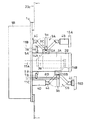
図1は、本発明の断路器付真空遮断器の第1の実施形態を示す右側面図で、従来の技術で示した図7に対応し、請求項1及び請求項2に対応し、真空バルブの両側に接続された断路器が開極状態を示す。
【0040】
図1において、従来の技術で示した図7と大きく異なるところは、真空遮断器とこの真空遮断器の電源側及び負荷側に接続される接地端子付断路器をこれらの各操作機構部とともに一体のユニットとして組み込んだことである。
【0041】
すなわち、図示しない金属閉鎖形スイッチギヤの箱体の前方に縦設された隔壁23cに形成された開口部に対して取付板1aと図示しないOリングを介して取り付けられた操作機構部1Aには、真空遮断器の真空バルブを入・切する詳細省略したバルブ操作機構1bと、遮断部の上下に対して以下説明するように組み込まれた断路部を操作する断路操作機構1c,1dが組み込まれている。
【0042】
3本の真空バルブ3Aを収納する絶縁筒2Aには、主回路側と接地側に切り換える断路器9A,9Bが以下説明するように組み込まれている。
このうち、絶縁筒2Aは、操作機構部1Aの取付板1aの裏面の中央部に対して水平に設けられ、絶縁筒2Aの前端に埋設された6個の図示しない埋金に取付板1aの前方から螺合されるボルトで固定されている。
【0043】
絶縁筒2Aの内部には、真空バルブ3が収納され、この真空バルブ3の固定側通電軸の後端は、絶縁筒2Aの後部に収納され固定された図1においてL字形の接続導体13の上部前面に固定されている。
【0044】
真空バルブ3Aの上部には、L字形に形成された接続導体12Aが固定され、真空バルブ3Aの可動側通電軸3aは、接続導体12Aに挿着された図示しない接触環を貫通している。
【0045】
可動側通電軸3aの前端に連結された絶縁棒11Aは、取付板1aに挿入され固定された図示しない環状のシールケースを貫通し、電動機で駆動されるバルブ操作機構部1bに前端が連結されている。
【0046】
接続導体12Aの上面の後部には、図示しない正面図では逆T字状のブレード支え10Aが固定され、絶縁筒2Aの下部に取り付けられた接続導体13 Aの下面の前端にも、ブレード支え10Aと同一品のブレード支え10Bが固定されている。
【0047】
このブレード支え10A,10Bには、このブレード支え10A,10Bを貫通したボルトと圧縮コイルばねを介して一対のブレード9aの基端が揺動自在に設けられ、このブレード9aの中間部に対して絶縁棒8A,8Bの後端が図示しないピンを介して連結されている。
【0048】
一方、取付板1aの裏面には、図示しない平面図では左右の両側に対してL字形に形成された一対の支え5A,5Bが固定され、これらの支え5A,5Bの間には、支軸6A,6Bが図1の紙面直交方向に貫設されている。
【0049】
これらの支軸6A,6Bには、各断路器9A,9Bのブレード9aと対向する位置に対してレバー7A,7Bの基端が固定され、このレバー7A,7Bの先端には、前述した絶縁棒8A,8Bの基端が連結されている。これらの絶縁棒8A,8Bの先端は、各断路器9A,9Bのブレード9aの中間部に連結されている。
【0050】
支軸6A,6Bには、図示しない操作レバーの基端が第2相と第3相の間に固定され、この操作レバーの先端には、操作棒11B,11Cの一端が連結され、これらの操作棒11B,11Cの他端は、断路器操作機構1c,1dに連結されている。
【0051】
各レバー7Aの上方と各レバー7Bの下方には、接地端子台4Aが設けられ、取付板1aに固定されている。各接地端子台4Aの背面側には、ブレード4aが突設されている。
【0052】
各断路器9A,9Bの後端の上方と下方には、上部母線と下部母線の前面側に固定された母線側端子台4Bが対置している。絶縁筒2Aの後端面には、下端が接続導体13Aに接続されたセットフランジ2aが固定されている。
【0053】
このように構成された断路器付真空遮断器においては、操作機構部1Aに組み込まれた操作機構1bを駆動することで、絶縁操作棒11Aを駆動し、真空バルブ3Aを開閉する。
また、上下の断路器9A,9Bを投入し、開極する場合には、操作機構1c,1dを駆動し、操作棒11B,11Cを駆動して、ブレード9aを揺動させる。
【0054】
このように構成された断路器付真空遮断器においては、三相共通の絶縁筒2Aに対して、断路器9A,9Bを固定するとともに、共通の操作機構部1Aに対して、真空バルブと上下の断路器の操作機構を組み込むことで、真空遮断器とこの真空遮断器の両極に接続される断路器及び接地断路部を取付ベース1aに一体に組み込むことができ、断路器を含めた外形を小形化することができる。
【0055】
したがって、従来の技術で示した図7のガス絶縁金属閉鎖形スイッチギヤと比べて箱体の外形を大幅に縮小することができるので、多様な仕様の受電設備にも容易に対応することができるだけでなく、取付ベース1aに一体にユニットとして組み込むことができるので、組立時間を大幅に短縮することができ、品質を安定させることもできる。
【0056】
図2は、本発明の断路器付真空遮断器の第2の実施形態を示す右側面図で、第1の実施形態で示した図1の他の実施例に対応し、真空バルブの両極に接地兼用の断路器が組み込まれ接続されている点は図1と同様である。
異なるところは、上下の断路器が真空バルブの前後の位置にずれて対称的に配置されていることで、他は、図1と同一である。
【0057】
すなわち、絶縁筒2Bの上面には、真空バルブ3Aの前端の上方の位置にブレード9aの基端を支えるブレード支え10Aが接続導体14Aの上端に固定され、絶縁筒2Bの下面には、接続導体14Bの下面に対して、ブレード支え10Bが固定されている。
【0058】
前述した真空バルブ3Aの可動側通電軸3aに図示しない接触環を介して片側が接続された接続導体14Aは、台形状に折り曲げられ、同じく、真空バルブ3Aの固定側通電軸の後端に片側が接続された接続導体14Bも、接続導体14Aと同一形状となっている。
【0059】
取付板1aの背面の上部に固定された接地端子台4Cは、図1で示した接地端子台4Aと比べて高さが低く、取付板1aの背面の下部に固定された接地端子台4Dは、逆に長くなっている。
【0060】
同様に、上側のブレード9aに後端が連結された絶縁棒8Cは、図1で示した絶縁棒8Aと比べて短く、下側のブレード9bに連結された絶縁棒8Dは長くなっている。したがって、上部の断路器9Aは絶縁筒2Bの中央部よりも前方に、下部の断路器9Bは中央部よりも後方となっている。
【0061】
このように構成された断路器付真空遮断器においては、接続導体14A,14Bに流れる短絡電流によって発生する電磁力を軽減することができるだけでなく、箱体側の機器の配置の制約によっては、上下の断路器の位置を逆とすることで、多様な仕様のガス絶縁金属閉鎖形スイッチギヤに対応することもできる。
【0062】
次に、図3は、本発明の断路器付真空遮断器の第3の実施形態を示す部分拡大図で、前述した実施形態で示した図1及び図2に対応し、請求項3に対応する図である。
【0063】
図3において、前述した実施形態で示した図1及び図2と異なるところは、上下の断路器の母線側の端子台などを絶縁筒に一体に組み込んで、端子台とともに自動連結構造としたことである。
【0064】
すなわち、図1及び図2で示した絶縁筒2A,2Bと比べて奥行きがやや深く製作された絶縁筒2Cの上下(注;下側は省略したが、上側と対称的である。)には、各ブレード9aの後方の位置に対して、絶縁台15が載置され、これらの各絶縁台15には、母線側端子台4Eが立設され固定されている。
これらの母線側端子台4Eの前面側に対して、前述した実施形態で示した固定側のブレード4aが同様に取り付けられている。
【0065】
さらに、母線側端子台4Eの裏面には、図示しない環状の加圧ばねを備えた接触子25Aが設けられ、箱体側に固定された支持碍子24に下端が固定された母線16Aの前面に突設された母線側端子と対置し嵌合している。
【0066】
このように構成された断路器付真空遮断器においては、組立時には接触子を介して母線16Aに接続することができるので、箱体の組立と保守・点検が更に容易となる。
【0067】
図4は、本発明の断路器付真空遮断器の第4の実施形態を示す部分拡大図で、前述した実施形態で示した図1〜図3に対応し、特に請求項5に対応する図である。
図4において、前述した実施形態と異なるところは、断路器の構成で、断路部が直線的に駆動されることである。
【0068】
すなわち、絶縁筒2Dの上面に立設された支持導体18には、断路器9Cを構成する端子筒19が図示しない接触板を介して前後方向に貫挿され、この端子筒19の後端の外周には、複数の接触子19aが環状に配置され、図示しない密着コイルばねで端子筒19の外周面に片側が押圧されている。
【0069】
端子筒19の前端には、絶縁棒17の片側が挿入され、この絶縁棒17の前端は、断路器操作機構に連結されている。
端子筒19の後方には、母線24の前端に固定された母線側端子20が対置している。なお、絶縁筒2Dの下側にも、真空バルブの他側を入切する同様な断路器が取り付けられている。
【0070】
このように構成された断路器付真空遮断器においては、箱体側の仕様によって、この箱体の内部に収納される電気機器の配置に伴い、上下方向の高さが制約され、奥行きの制約の緩い箱体に適用することで、この箱体の実装密度を上げ、設置床面積を減らすことができる。
【0071】
図5は、本発明の断路器付真空遮断器の第5の実施形態を示す右側面拡大図で、請求項4に対応し、前述した図1〜図3に対応し、接地断路部を母線側の断路器の両極側(すなわち、母線も接地可能)に設けた場合を示す。
【0072】
すなわち、上方の接地端子台4Aの上部には、母線用の接地断路器21Aの支え21aが固定され、下側の接地端子台4Bの下方にも、母線用の接地断路器21Bの支え21bが固定されている。これらの接地断路器21A,21Bの前方には、これらの接地断路器21A,21Bを駆動する絶縁操作棒11D,11Eが示されている。
【0073】
一方、絶縁筒2Aの後部の上方には、接続端子台29Aが設けられ、この接続端子台29Aには、L字形に形成された接続導体28Aの下端が接続され、この接続導体28Aの上部は、碍子27の下面に固定されている。
【0074】
この碍子27は、上端が紙面直交方向に設けられた共通の取付板に取り付けられ、この取付板は、取付板1aの両側から前方に突き出た支え30Aで両端が支持されている。
【0075】
この碍子27の下面には、水平に設けられた接続導体26Aの中間部が固定され、この接続導体26Aの前端には、ブレード27aの後端がろう付されている。
接続導体26Aの後端には、接触子25Bが取り付けられ、この接触子25Bは、箱体の内部に縦設された二点鎖線で示す母線16Aの下端の前面の母線側の端子に嵌合している。
【0076】
一方、絶縁筒2Aの後部の下方にも、接続端子台29Bが設けられ、この接続端子台29Bにも、L字形に形成された接続導体28Bの上端が接続され、この接続導体28Bの下部は、碍子27の上面に固定されている。
【0077】
この碍子27の上面には、水平に設けられた接続導体26Bの中間部が固定され、この接続導体26Bの前端には、ブレード27aの後端がろう付されている。
接続導体26Bの後端には、接触子25Bが取り付けられ、この接触子25Bは、箱体の内部に縦設された二点鎖線で示す母線16Bの下端の前面の端子に嵌合している。
【0078】
このように構成された断路器付真空遮断器においては、図1で示した断路器付真空遮断器と比べて、上下端に設けられた接地断路器21A,21Bとこれらの後方に取り付けられた接触子25B,25Cとともに取付板1aにユニットとして組み込まれる。
【0079】
したがって、箱体の内部で組み立てる作業と比べて、作業性を大幅に上げることができるので、ばらつきの少ない品質一定の断路器付真空遮断器を得ることができる。
【0080】
図6は、本発明の断路器付真空遮断器の第6の実施形態を示す右側面図で、請求項7及び請求項8に対応し、前述した実施形態で示した図1〜図5に対応する図である。
【0081】
図6において、前述した実施形態で示した図1〜図5と大きく異なるところは、操作機構部の後部に対して、上中下段に絶縁筒を水平に設け、このうち、中段の絶縁筒には、前述した実施形態と同様に内部に一対の電極を収納した真空バルブを収納し、上下の絶縁筒には、断路器を以下説明するように収納したことである。
【0082】
すなわち、取付ベース1aの背面の中央部には、絶縁筒2Eの前端が固定され、この絶縁筒2Eの上下にも絶縁筒2Fが対称的に配置され、取り付けられている。
このうち、中央部の絶縁筒2Eには、前述した実施形態と同様に真空バルブ3Aがその可動側通電軸が操作機構部側を向くように水平に収納され、この真空バルブ3Aの前方には、L字形の接続導体12Bが固定されている。
【0083】
上下の絶縁筒2Fにも、断路器9Dの容器となる真空バルブ3Bが水平に収納され、この真空バルブ3Bの前端を図示しないベローズを介して気密に貫通した可動側通電軸3bは、図示しない接触環を介して接続導体12Cを貫通し、絶縁棒11Fに連結されている。
【0084】
この絶縁棒11Fの前端は、操作機構部1Fに組み込まれた図示しない断路器操作機構1c,1dに連結されている。
可動側通電軸3bの後端には、図4で示した端子筒19が前後方向に貫挿されろう付されている。この端子筒19の後端の外周に形成された溝には、複数の接触子19aが環状に配置され、図示しない密着コイルばねで端子筒19の外周面に片側が押圧されている。
【0085】
端子筒19の後方には、固定側通電軸の前端にろう付された端子20が対置している。このうち、上側の真空バルブ3Bの固定側通電軸の後端は、絶縁筒2Fの後方に固定されたL字形の接続導体13Bの後端上部がろう付されている。
この接続導体13Bの前端は、真空バルブ3Aの前方に固定され前述した接続導体12Bの上端に接続された接続導体12Eの上端に接続されている。
【0086】
下側の真空バルブ3Bの固定側通電軸の後端は、セットフランジ2aを貫通し、この固定側通電軸の後端には、接続導体12Dの下端が接続され、この接続導体12Dの上端は、中央部の絶縁筒2Eのセットフランジ2aに固定されている。
【0087】
上端の接続導体12Cの上端の後面には、図3で示した接触子25Aと同一品の接触子25Aの前端が取り付けられ、下端の接続導体12Cの下端の後面にも接触子25Aが取り付けられている。
【0088】
これらの接触子25Aの後方には、L字形に形成された母線24が二点鎖線で示され、これらの母線24の下端の前面にろう付された母線側端子に対して、接触子25Aの後部が嵌合し、上下の断路器9Dは、接触子25Aを介して母線24に接続されている。
【0089】
このように構成された断路器付真空遮断器においても、前述した実施形態の図1〜図5で示した断路器付真空遮断器と同様に、遮断部となる真空バルブと、その両極側の断路器を共通の操作機構1Fの取付板1aに固定することでユニットに一体化され、組立が容易で且つ品質管理も容易となる。
【0090】
また、断路器の断路部を真空バルブの内部に収納することで、外形を小形化することができるので、断路器付真空遮断器の小形化を図ることができ、この断路器付真空遮断器を収納する金属閉鎖形スイッチギヤの箱体の内部の機器の配置の制約を緩和することができるので、箱体の設計と製作及び保守が容易となるだけでなく、この箱体が設置される受電設備の所要床面積を減らすことができる。
【0091】
さらに、従来のガス絶縁金属閉鎖形スイッチギヤのガス絶縁媒体として採用されている六フッ素ガスによって小形化を図ることなく、断路器付真空遮断器によって箱体を小形化することができるので、大気汚染などの環境に配慮した断路器付真空遮断器とすることができる。
【0092】
【発明の効果】
以上、請求項1に対応する発明によれば、真空バルブの可動側通電軸を駆動するバルブ駆動部と一対の断路器駆動部を収納する操作機構部の後部に可動側通電軸を前方にして真空バルブを収納する絶縁筒を設け、この絶縁筒の上下に絶縁棒で断路器駆動部に連結される断路器を軸支部を介して取り付けることで、遮断部と断路部を操作機構とともにユニットに一体化して、小形化し組立を容易にするとともに、箱体側への組立に要する時間及び箱体に占める空間を減らし、保守・点検時間も短縮したので、箱体の設置場所の制約を減らすことのできる断路器付真空遮断器を得ることができる。
【0093】
また、特に請求項2に対応する発明によれば、断路器駆動部による絶縁棒の前方駆動で断路器のブレードが投入される接地端子を操作機構部の後部の上下に設け、絶縁棒の後方駆動で断路器のブレードが投入される主回路端子を断路器の後方に設けることで、遮断部と接地端子付断路部を操作機構とともにユニットに一体化して、小形化し組立を容易にするとともに、箱体側への組立に要する時間及び箱体に占める空間を減らし、保守・点検時間も短縮したので、箱体の設置場所の制約を減らすことのできる断路器付真空遮断器を得ることができる。
【0094】
また、特に請求項3に対応する発明によれば、主回路端子を絶縁筒に固定し、収納箱体の固定側接触具に嵌合する可動側接触具を主回路端子の後部に設けることで、遮断部と断路部を操作機構とともにユニットに一体化して、小形化し組立を容易にするとともに、箱体側への組立に要する時間及び箱体に占める空間を減らし、保守・点検時間も短縮したので、箱体の設置場所の制約を減らすことのできる断路器付真空遮断器を得ることができる。
【0095】
また、特に請求項4に対応する発明によれば、操作機構部の後部の上側の接地端子の上方と下側の接地端子の下方に接地断路器を設け、この接地断路器の接地動作で後方に揺動する接地ブレードと接触部を介して接続され後端が主回路端子に接続された接続導体と、この接続導体を碍子を介して操作機構に支持する支持具と、接続導体の後端に固定され収納箱体の固定側接触具に接続される可動側接触具と、操作機構部に収納され接地断路器を絶縁棒を介して駆動する接地断路器駆動部とを備えることで、遮断部と断路部及び接地断路器を操作機構とともにユニットに一体化して、小形化し組立を容易にするとともに、箱体側への組立に要する時間及び箱体に占める空間を減らし、保守・点検時間も短縮したので、箱体の設置場所の制約を減らすことのできる断路器付真空遮断器を得ることができる。
【0096】
また、特に請求項5に対応する発明によれば、絶縁棒の後端に設けられた可動側接触子と、収納箱体に固定され可動側接触子と嵌合する固定側接触子を断路器に備えることで、遮断部と断路部を操作機構とともにユニットに一体化して、小形化し組立を容易にするとともに、箱体側への組立に要する時間及び箱体に占める空間を減らし、保守・点検時間も短縮したので、箱体の設置場所の制約を減らすことのできる断路器付真空遮断器を得ることができる。
【0097】
また、特に請求項6に対応する発明によれば、片側の接触部を可動側通電軸が貫通し他側が断路器の軸支部に接続される接続導体を絶縁筒に固定することで、遮断部と断路部を操作機構とともにユニットに一体化して、小形化し組立を容易にするとともに、箱体側への組立に要する時間及び箱体に占める空間を減らし、保守・点検時間も短縮したので、箱体の設置場所の制約を減らすことのできる断路器付真空遮断器を得ることができる。
【0098】
また、請求項7に対応する発明によれば、真空バルブの可動側通電軸を駆動するバルブ駆動部及び一対の断路器駆動部を収納する操作機構部と、前記可動側通電軸を操作機構部側に向けて前記真空バルブを収納し、前記操作機構部の後部に固定されるバルブ絶縁筒と、前記バルブ絶縁筒の上下に配置され、前記断路器駆動部に連結される絶縁棒に可動側通電軸を介して接続される可動側接触子、および前記可動側接触子と嵌合する固定側接触子とからなる断路器真空バルブを収納し、前記操作機構部の後部に取り付けられる断路器絶縁筒とを備えたので、遮断部と断路器バルブで小形化した断路部を操作機構とともにユニットに一体化して、小形化し組立を容易にするとともに、箱体側への組立に要する時間及び箱体に占める空間を減らし、保守・点検時間も短縮したので、箱体の設置場所の制約を減らすことのできる断路器付真空遮断器を得ることができる。
【0099】
さらに、特に請求項8に対応する発明によれば、真空バルブの可動側通電軸が片側を貫通する接続導体の他側及び片側の断路器バルブの固定側を接続する第1の接続導体と、真空バルブの固定側と他側の断路器バルブの固定側を接続する第2の接続導体と、片側と他側の断路器バルブの可動側通電軸が片側を貫通し他側に可動側接触部が固定された第3の接続導体とを備えることで、遮断部と断路部を操作機構とともにユニットに一体化して、小形化し組立を容易にするとともに、箱体側への組立に要する時間及び箱体に占める空間を減らし、保守・点検時間も短縮したので、箱体の設置場所の制約を減らすことのできる断路器付真空遮断器を得ることができる。
【図面の簡単な説明】
【図1】本発明の断路器付真空遮断器の第1の実施形態を示す右側面図。
【図2】本発明の断路器付真空遮断器の第2の実施形態を示す右側面図。
【図3】本発明の断路器付真空遮断器の第3の実施形態を示す部分右側面図。
【図4】本発明の断路器付真空遮断器の第4の実施形態を示す部分右側面図。
【図5】本発明の断路器付真空遮断器の第5の実施形態を示す右側面図。
【図6】本発明の断路器付真空遮断器の第6の実施形態を示す右側面図。
【図7】従来の断路器付真空遮断器の一例を示す右側面図。
【符号の説明】
1A,1B,1C,1D,1E,1F…操作機構部、1a…取付板、1b…バルブ操作機構部、1c,1d…断路器操作機構部、2A,2B,2C,2D,2E,2F…絶縁筒、3A,3B…真空バルブ、4A,4C…接地端子台、4B,4D…母線端子台、4a…ブレード、5A,5B…支え、6A,6B…支軸、7A,7B…レバー、8A,8B,8C,8D,17…絶縁棒、9A,9B,9C,9D…断路器、10A,10B…ブレード支え、11A,11D,11E…絶縁操作棒、11B,11C…操作棒、12A,12B,13A,14A,14B…接続銅帯、15…絶縁台、16A,16B…母線、18…支持導体、19…端子筒、20…母線側端子、21A,21B…接地断路器、22…支持碍子、23…箱体、24…母線、25A…接触子、26A,26B…接続導体、27…碍子、28A,28B…接続導体、29A,29B…接続端子台、30A,30B…支え。[0001]
BACKGROUND OF THE INVENTION
The present invention relates to a vacuum circuit breaker with a disconnector.
[0002]
[Prior art]
FIG. 7 is a right side view showing an example of a gas insulated metal closed switchgear in which a disconnecting switch with a grounding device is housed together with a vacuum circuit breaker, and shows a case of a power receiving panel.
In FIG. 7, a
[0003]
An L-
[0004]
As a result, the
[0005]
Of these, an opening portion, which is omitted in detail, is formed in the upper portion of the
[0006]
At the upper end of the disconnecting portion of the disconnecting
[0007]
At the lower end of the L-
[0008]
Below the
The upper terminal projecting from the rear upper part of the high-pressure vacuum circuit breaker 38 is connected to the terminal at the lower end of the
[0009]
An upper end of a conductor 42F disposed vertically below the lower terminal is connected to a lower terminal protruding from the lower rear side of the high-pressure vacuum circuit breaker 38. The conductor 42F is connected to the center of the
[0010]
Below the high-pressure vacuum circuit breaker 38, a
[0011]
The lower end of the conductor 42F described above is connected to the upper terminal of the
The
[0012]
A
[0013]
The flange 23d welded to the central portion of the ceiling plate of the
[0014]
The T-
[0015]
A high-pressure cross-linked polyethylene cable (hereinafter referred to as a cable) 34 is connected to both ends of these T-
[0016]
The other end (not shown) of each
On the other hand, a
[0017]
A pair of through-type
[0018]
Operation mechanism part of
The front ends of the L-shaped connection conductors are fixed with bolts on the rear surfaces of these insulators, and a rectangular connection conductive plate is brazed to the center of the opposing surfaces of these connection conductors. Further, one side of the ground terminal bent at an obtuse angle is fixed to the upper connection conductor with a bolt.
[0019]
The lower connection guide plate supports the base ends of the pair of blades via a support shaft via a pressure spring (not shown). The tip of the blade is engaged with the upper connection guide plate in accordance with the backward operation of the insulating operation lever protruding rearward from the drive mechanism portion incorporated in the operation mechanism portion 37a and is in the input state.
[0020]
Above the disconnector mount, the bearing is the operating mechanism.ThreeIt protrudes behind 7a. The base end of the blade of the
[0021]
The
In the disconnector with grounding device configured in this way, the blades of the
[0022]
In the gas-insulated metal closed switchgear configured as described above, sulfur hexafluoride gas (SF) is placed in the hermetic chamber between the
[0023]
Due to the insulating properties of the
[0024]
[Problems to be solved by the invention]
However, even in the gas-insulated metal closed switchgear configured as described above, a large space is required in the vertical direction because the upper and
[0025]
That is, in FIG. 7, in order to obtain a predetermined insulating gap between the tip of the blade at the time of disconnection indicated by the chain line and the contact inserted by the tip of the blade, the opening angle θ of the blade must be increased. .
[0026]
Then, since the operation stroke and the swing angle of the insulating operation lever are also increased, not only the drive mechanism inside the operation mechanism portion 37a becomes large, but also the sealing structure of the base portion of the insulating operation lever becomes complicated.
[0027]
In addition, there is a method to reduce the stroke of the insulation operation lever by moving the connecting part between the tip of the insulation operation lever and the blade to the base end side of the blade, but this method does not increase the driving force of the insulation operation lever. Therefore, the drive mechanism of the operation mechanism section becomes large.
[0028]
Therefore, since the height of the box installed in the basement of the building cannot be reduced, it is impossible to prevent the workability of the cable connection work of the T-shaped bushing penetrating through the upper end of the box.
[0029]
On the other hand, as the land price of the city rises and the size of the building increases, there is an increasing demand for downsizing the large-capacity power receiving equipment installed in this large building. Further miniaturization is required.
Then, the objective of this invention is obtaining the vacuum circuit breaker with a disconnector which can reduce the restrictions of the installation place of a box.
[0030]
[Means for Solving the Problems]
According to a first aspect of the present invention, there is provided a vacuum circuit breaker with a disconnector having a movable side energizing shaft at a rear portion of a valve driving unit that drives a movable side energizing shaft of a vacuum valve and an operation mechanism unit that houses a pair of disconnector driving units. Insulating cylinders that house the vacuum valve are provided in the front, and disconnectors connected to the disconnector drive unit by insulating rods are provided above and below the insulating cylinders via shaft support parts.MountingCharacterized by
[0031]
Further, in the vacuum circuit breaker with disconnector of the invention corresponding to claim 2 in particular, the grounding terminal into which the blade of the disconnector is inserted by the front drive of the insulating rod by the disconnector driving part is provided above and below the rear part of the operation mechanism part. The main circuit terminal into which the blade of the disconnector is inserted by the rear drive of the insulating rod is provided at the rear of the disconnector.
[0032]
Further, in the vacuum circuit breaker with disconnector of the invention corresponding to claim 3 in particular, the main circuit terminal is fixed to the insulating cylinder, and the movable side contact that is fitted to the fixed side contact of the storage box is provided on the main circuit terminal. It is provided in the rear part.
[0033]
According to a fourth aspect of the present invention, there is provided a disconnector-equipped vacuum circuit breaker provided with a ground disconnector above the upper grounding terminal at the rear of the operation mechanism and below the lower grounding terminal. A connection conductor connected via a contact portion to a grounding blade that swings backward in the grounding operation of the contact terminal, and a rear end connected to the main circuit terminal, and a support that supports the connection conductor on the operation mechanism via an insulator, A movable contact that is fixed to the rear end of the connection conductor and connected to the fixed contact of the storage box, and a ground disconnector drive that is housed in the operation mechanism and drives the ground disconnector via an insulating rod. It is characterized by having.
[0034]
Moreover, the vacuum circuit breaker with a disconnector of the invention corresponding to claim 5 in particular includes a movable contact provided at the rear end of the insulating rod, and a fixed side fixed to the storage box body and fitted to the movable contact. A contactor is provided in the disconnector.
[0035]
Further, in the vacuum circuit breaker with disconnector of the invention corresponding to claim 6 in particular, the connecting conductor in which the movable-side energizing shaft passes through the contact portion on one side and the other side is connected to the shaft support portion of the disconnector is fixed to the insulating cylinder. It is characterized by that.
[0036]
According to a seventh aspect of the present invention, there is provided a vacuum circuit breaker with a disconnecting device, comprising: a valve driving unit that drives a movable side energizing shaft of a vacuum valve; an operating mechanism unit that houses a pair of disconnecting unit driving units; AxisToward the operation mechanismContains the vacuum valveAnd saidAfter the operation mechanismPartFixedRuA valve insulation tube;AboveUpper and lower of valve insulation cylinderPlaced inA movable contact connected to an insulating rod coupled to the disconnector drive unit via a movable energizing shaft;And saidFixed contact that mates with movable contactThe disconnector vacuum valve consisting ofAt the rear of the operating mechanismIt is attachedA disconnector insulating cylinder is provided.
[0037]
Further, in the vacuum circuit breaker with disconnector of the invention corresponding to claim 8 in particular, the movable side energizing shaft of the vacuum valve connects the other side of the connecting conductor penetrating one side and the fixed side of the one side disconnector valve. Connecting conductor, the second connecting conductor connecting the fixed side of the vacuum valve and the fixed side of the disconnector valve on the other side, and the movable side energizing shaft of the disconnector valve on one side and the other side penetrates one side and the other side And a third connection conductor having a movable contact portion fixed thereto.
[0038]
By such means, in the inventions of the first to eighth aspects, the blocking portion and the disconnecting portion are integrated with the unit together with the operation mechanism to reduce the size and facilitate the assembly, and to the box side. This reduces the time required for the operation and the space occupied by the box, and shortens the maintenance and inspection time.
[0039]
DETAILED DESCRIPTION OF THE INVENTION
Hereinafter, an embodiment of a vacuum circuit breaker with a disconnector of the present invention will be described with reference to the drawings.
FIG. 1 is a right side view showing a first embodiment of a vacuum circuit breaker with a disconnector according to the present invention, corresponding to FIG. 7 shown in the prior art, corresponding to claim 1 and claim 2, and a vacuum. Disconnectors connected to both sides of the valve indicate the open state.
[0040]
In FIG. 1, the point that is greatly different from FIG. 7 shown in the prior art is that a vacuum circuit breaker and a disconnector with a ground terminal connected to the power supply side and the load side of the vacuum circuit breaker are integrated together with each of these operation mechanisms. It is built in as a unit.
[0041]
That is, the
[0042]
Among these, the insulating
[0043]
A
[0044]
An L-shaped connecting
[0045]
The insulating
[0046]
An inverted T-shaped
[0047]
The blade supports 10A and 10B are provided with a base end of a pair of
[0048]
On the other hand, on the back surface of the mounting
[0049]
The base ends of the
[0050]
A base end of an operation lever (not shown) is fixed between the second phase and the third phase on the
[0051]
A
[0052]
A bus-
[0053]
In the vacuum circuit breaker with disconnector configured as described above, by driving the
Further, when the upper and
[0054]
In the vacuum breaker with disconnector configured as described above, the
[0055]
Accordingly, since the outer shape of the box can be greatly reduced as compared with the gas insulated metal closed switchgear of FIG. 7 shown in the prior art, it can be easily adapted to power receiving equipment of various specifications. In addition, since it can be integrated into the mounting
[0056]
FIG. 2 is a right side view showing a second embodiment of the vacuum circuit breaker with disconnector according to the present invention, corresponding to the other example of FIG. 1 shown in the first embodiment, and at both poles of the vacuum valve. The grounding disconnect switch is incorporated and connected as in FIG.
The difference is that the upper and lower disconnectors are symmetrically arranged at the positions before and after the vacuum valve, and the others are the same as in FIG.
[0057]
That is, on the upper surface of the insulating
[0058]
The connection conductor 14A, one side of which is connected to the movable
[0059]
The
[0060]
Similarly, the insulating rod 8C whose rear end is connected to the
[0061]
In the vacuum circuit breaker with disconnector configured in this way, not only can the electromagnetic force generated by the short-circuit current flowing in the connection conductors 14A and 14B be reduced, but depending on the restrictions on the arrangement of the equipment on the box side, By reversing the positions of the upper and lower disconnectors, it is possible to accommodate gas-insulated metal closed switch gears of various specifications.
[0062]
Next, FIG. 3 is a partially enlarged view showing a third embodiment of the vacuum circuit breaker with disconnector of the present invention, corresponding to FIG. 1 and FIG. 2 shown in the above-described embodiment, and corresponding to claim 3. It is a figure to do.
[0063]
3 differs from FIGS. 1 and 2 shown in the above-described embodiment in that the terminal block on the busbar side of the upper and lower disconnectors is integrated into the insulating cylinder, and the automatic connection structure is made together with the terminal block. It is.
[0064]
That is, the upper and lower sides of the insulating cylinder 2C manufactured slightly deeper than the insulating
The fixed-
[0065]
Further, a
[0066]
In the vacuum circuit breaker with disconnector configured as described above, it can be connected to the
[0067]
FIG. 4 is a partially enlarged view showing a fourth embodiment of the vacuum circuit breaker with disconnector of the present invention, corresponding to FIGS. 1 to 3 shown in the above-described embodiment, and particularly corresponding to claim 5. It is.
In FIG. 4, the difference from the above-described embodiment is that the disconnecting portion is linearly driven by the disconnector configuration.
[0068]
That is, a
[0069]
One end of the insulating
A bus-
[0070]
In the vacuum circuit breaker with disconnector configured in this way, the height in the vertical direction is restricted according to the arrangement of the electrical equipment stored inside the box depending on the specifications on the box side, and the depth restriction By applying to a loose box, the mounting density of the box can be increased, and the installation floor area can be reduced.
[0071]
FIG. 5 is a right side enlarged view showing a fifth embodiment of the vacuum circuit breaker with disconnector according to the present invention, corresponding to claim 4 and corresponding to FIGS. The case where it is provided on both pole sides (that is, the busbar can be grounded) of the side disconnector is shown.
[0072]
That is, the
[0073]
On the other hand, a
[0074]
The
[0075]
An intermediate portion of a connecting
A
[0076]
On the other hand, a
[0077]
An intermediate portion of a horizontally provided
A
[0078]
In the vacuum circuit breaker with disconnector configured in this way, compared to the vacuum circuit breaker with disconnector shown in FIG. 1, the
[0079]
Therefore, the workability can be greatly improved as compared with the work of assembling inside the box, and therefore a vacuum circuit breaker with a disconnector having a constant quality with little variation can be obtained.
[0080]
FIG. 6 is a right side view showing a sixth embodiment of the vacuum circuit breaker with disconnector of the present invention, corresponding to claims 7 and 8, corresponding to FIGS. 1 to 5 shown in the above-described embodiment. It is a corresponding figure.
[0081]
In FIG. 6, the main difference from FIGS. 1 to 5 shown in the above-described embodiment is that an insulating cylinder is provided horizontally in the upper, middle, and lower stages with respect to the rear part of the operation mechanism part. As described above, a vacuum valve that houses a pair of electrodes is housed in the same manner as in the above-described embodiment, and disconnectors are housed in the upper and lower insulating cylinders as described below.
[0082]
That is, the front end of the insulating cylinder 2E is fixed to the central portion of the back surface of the mounting
Among them, the central insulating cylinder 2E has a
[0083]
Also in the upper and lower insulating
[0084]
The front end of the insulating
A
[0085]
A terminal 20 brazed to the front end of the fixed-side energizing shaft is disposed behind the
The front end of the
[0086]
The rear end of the fixed energizing shaft of the
[0087]
The front end of the
[0088]
L-shaped
[0089]
Also in the vacuum circuit breaker with disconnector configured in this way, as with the vacuum circuit breaker with disconnector shown in FIGS. The disconnector is attached to the mounting
[0090]
Also, since the outer shape can be reduced by storing the disconnecting part of the disconnector in the vacuum valve, the vacuum interrupter with disconnector can be miniaturized. It is possible not only to ease the design, production and maintenance of the box, but also to install this box. The floor space required for the power receiving equipment can be reduced.
[0091]
Furthermore, the box can be miniaturized by the vacuum circuit breaker with disconnector without reducing the size by the hexafluoro gas employed as the gas insulating medium of the conventional gas insulated metal closed switchgear. It can be a vacuum circuit breaker with disconnector considering the environment such as contamination.
[0092]
【The invention's effect】
As described above, according to the invention corresponding to the first aspect, the movable side energizing shaft is disposed at the front of the valve drive unit that drives the movable side energizing shaft of the vacuum valve and the operation mechanism unit that houses the pair of disconnector drive units. Insulating cylinders that house the vacuum valve are provided, and disconnectors connected to the disconnector driving unit by insulating rods are provided above and below the insulating cylinders via the shaft support parts.MountingBy integrating the shut-off section and disconnecting section into the unit together with the operation mechanism, the unit is downsized to facilitate assembly, and the time required for assembly on the box side and the space occupied by the box body are reduced. Therefore, it is possible to obtain a vacuum circuit breaker with a disconnector that can reduce the restrictions on the installation location of the box.
[0093]
In particular, according to the invention corresponding to claim 2, the grounding terminals into which the blades of the disconnecting device are inserted by the front drive of the insulating rod by the disconnecting device driving portion are provided above and below the rear portion of the operating mechanism portion, and the rear of the insulating rod By providing the main circuit terminal to which the blade of the disconnector is driven by the drive at the rear of the disconnector, the interrupting part and the disconnecting part with the ground terminal are integrated into the unit together with the operation mechanism, and the size is reduced and the assembly is facilitated. Since the time required for assembling to the box body and the space occupied in the box body have been reduced, and the maintenance and inspection time has also been shortened, it is possible to obtain a vacuum circuit breaker with a disconnector that can reduce restrictions on the installation location of the box body. .
[0094]
According to the invention corresponding to claim 3 in particular, the main circuit terminal is fixed to the insulating cylinder, and the movable contact that fits to the fixed contact of the storage box is provided at the rear of the main circuit terminal. In addition, the shut-off part and disconnection part are integrated into the unit together with the operation mechanism, making it compact and easy to assemble, reducing the time required for assembly on the box side and the space occupied by the box, and shortening the maintenance and inspection time. Therefore, it is possible to obtain a vacuum circuit breaker with a disconnector that can reduce restrictions on the installation location of the box.
[0095]
According to the invention corresponding to claim 4 in particular, a grounding disconnector is provided above the grounding terminal on the upper side of the rear part of the operating mechanism and below the grounding terminal on the lower side, and the grounding operation of this grounding disconnector causes the rear A connecting conductor that is connected to the grounding blade swinging through the contact portion and whose rear end is connected to the main circuit terminal, a support that supports the connecting conductor on the operating mechanism via the lever, and a rear end of the connecting conductor It is cut off by providing a movable contact that is fixed to the fixed contact of the storage box and connected to the fixed contact of the storage box, and a ground disconnector drive unit that is stored in the operation mechanism unit and drives the ground disconnector via an insulating rod. The unit, disconnection unit and grounding disconnector are integrated into the unit together with the operation mechanism to reduce the size and facilitate assembly, reduce the time required for assembly on the box side and the space occupied by the box, and also provide maintenance and inspection time. Reduced restrictions on the installation location of the box because it was shortened It can be obtained disconnector with vacuum circuit breaker capable of Succoth.
[0096]
According to the invention corresponding to claim 5 in particular, the movable side contact provided at the rear end of the insulating rod, and the fixed side contact fixed to the storage box and fitted to the movable side contact are disconnected. As a result, the shut-off part and disconnecting part are integrated into the unit together with the operating mechanism, making it compact and facilitating assembly, reducing the time required for assembly on the box side and the space occupied by the box, and maintenance and inspection. Since the time has also been shortened, a vacuum circuit breaker with a disconnector that can reduce the restrictions on the installation location of the box can be obtained.
[0097]
Further, according to the invention corresponding to claim 6 in particular, the blocking portion is fixed by fixing the connecting conductor, which is connected to the shaft support portion of the disconnector on the other side of the movable side energizing shaft through the contact portion on one side, to the insulating cylinder. The unit is integrated into the unit together with the operating mechanism, making it smaller and easier to assemble, reducing the time required to assemble the box and the space occupied by the box, and shortening the maintenance and inspection time. It is possible to obtain a vacuum circuit breaker with a disconnector that can reduce restrictions on the place where the body is installed.
[0098]
According to the invention corresponding to claim 7, the valve drive unit that drives the movable side energizing shaft of the vacuum valve and the operation mechanism unit that houses the pair of disconnector drive units, and the movable side energized shaftToward the operation mechanismContains the vacuum valveAnd saidAfter the operation mechanismPartFixedRuA valve insulation tube;AboveUpper and lower of valve insulation cylinderPlaced inA movable contact connected to an insulating rod coupled to the disconnector drive unit via a movable energizing shaft;And saidFixed contact that mates with movable contactThe disconnector vacuum valve consisting ofAt the rear of the operating mechanismIt is attachedSince the disconnector insulation cylinder is provided, the disconnection part reduced in size by the breaker and disconnector valve is integrated into the unit together with the operating mechanism, making it smaller and easier to assemble, and the time required for assembly to the box side In addition, since the space occupied in the box is reduced and the maintenance and inspection time is also shortened, a vacuum circuit breaker with a disconnector that can reduce the restrictions on the installation location of the box can be obtained.
[0099]
Furthermore, according to the invention corresponding to claim 8 in particular, the first connection conductor connecting the other side of the connection conductor through which the movable side energizing shaft of the vacuum valve penetrates one side and the fixed side of the disconnector valve on one side; A second connecting conductor for connecting the fixed side of the vacuum valve and the fixed side of the disconnector valve on the other side, and the movable side energizing shaft of the disconnector valve on one side and the other side penetrates one side and the movable side contact part on the other side And a third connecting conductor to which the door is fixed so that the blocking portion and the disconnecting portion are integrated into the unit together with the operation mechanism to reduce the size and facilitate the assembly, and the time and box required for the assembly to the box side. Since the space occupied by the body is reduced and the maintenance / inspection time is also shortened, a vacuum circuit breaker with a disconnecting switch that can reduce restrictions on the installation location of the box can be obtained.
[Brief description of the drawings]
FIG. 1 is a right side view showing a first embodiment of a vacuum circuit breaker with disconnector according to the present invention.
FIG. 2 is a right side view showing a second embodiment of the vacuum circuit breaker with disconnector of the present invention.
FIG. 3 is a partial right side view showing a third embodiment of the vacuum circuit breaker with disconnector of the present invention.
FIG. 4 is a partial right side view showing a fourth embodiment of the vacuum circuit breaker with disconnector of the present invention.
FIG. 5 is a right side view showing a fifth embodiment of the vacuum circuit breaker with disconnector of the present invention.
FIG. 6 is a right side view showing a sixth embodiment of the vacuum circuit breaker with disconnector of the present invention.
FIG. 7 is a right side view showing an example of a conventional vacuum circuit breaker with a disconnector.
[Explanation of symbols]
1A, 1B, 1C, 1D, 1E, 1F ... operation mechanism, 1a ... mounting plate, 1b ... valve operation mechanism, 1c, 1d ... disconnector operation mechanism, 2A, 2B, 2C, 2D, 2E, 2F ... Insulating cylinder, 3A, 3B ... vacuum valve, 4A, 4C ... ground terminal block, 4B, 4D ... bus terminal block, 4a ... blade, 5A, 5B ... support, 6A, 6B ... support shaft, 7A, 7B ... lever, 8A , 8B, 8C, 8D, 17 ... Insulating rod, 9A, 9B, 9C, 9D ... Disconnector, 10A, 10B ... Blade support, 11A, 11D, 11E ... Insulating operating rod, 11B, 11C ... Operating rod, 12A, 12B , 13A, 14A, 14B ... connecting copper strip, 15 ... insulating base, 16A, 16B ... busbar, 18 ... support conductor, 19 ... terminal tube, 20 ... busbar side terminal, 21A, 21B ... ground disconnector, 22 ...
Claims (8)
Priority Applications (1)
| Application Number | Priority Date | Filing Date | Title |
|---|---|---|---|
| JP35423197A JP3612201B2 (en) | 1997-12-24 | 1997-12-24 | Vacuum circuit breaker with disconnector |
Applications Claiming Priority (1)
| Application Number | Priority Date | Filing Date | Title |
|---|---|---|---|
| JP35423197A JP3612201B2 (en) | 1997-12-24 | 1997-12-24 | Vacuum circuit breaker with disconnector |
Publications (2)
| Publication Number | Publication Date |
|---|---|
| JPH11185577A JPH11185577A (en) | 1999-07-09 |
| JP3612201B2 true JP3612201B2 (en) | 2005-01-19 |
Family
ID=18436168
Family Applications (1)
| Application Number | Title | Priority Date | Filing Date |
|---|---|---|---|
| JP35423197A Expired - Fee Related JP3612201B2 (en) | 1997-12-24 | 1997-12-24 | Vacuum circuit breaker with disconnector |
Country Status (1)
| Country | Link |
|---|---|
| JP (1) | JP3612201B2 (en) |
Cited By (1)
| Publication number | Priority date | Publication date | Assignee | Title |
|---|---|---|---|---|
| JP2007028776A (en) * | 2005-07-15 | 2007-02-01 | Mitsubishi Electric Corp | Gas insulated switchgear |
Families Citing this family (10)
| Publication number | Priority date | Publication date | Assignee | Title |
|---|---|---|---|---|
| JP3755639B2 (en) * | 2000-02-17 | 2006-03-15 | 三菱電機株式会社 | Switchgear |
| JP4334852B2 (en) * | 2002-10-31 | 2009-09-30 | 三菱電機株式会社 | Gas insulated switchgear |
| JP4329923B2 (en) | 2002-10-31 | 2009-09-09 | 三菱電機株式会社 | Gas insulated switchgear |
| TWI228339B (en) * | 2002-11-06 | 2005-02-21 | Mitsubishi Electric Corp | Metal-enclosed switchgear |
| JP4906892B2 (en) * | 2009-08-12 | 2012-03-28 | 株式会社日立製作所 | Switchgear |
| DE102010004919A1 (en) * | 2009-11-06 | 2011-05-12 | Areva Energietechnik Gmbh | Single or double pole electrical switchgear, especially medium voltage switchgear |
| JP5183794B2 (en) * | 2011-11-24 | 2013-04-17 | 株式会社日立製作所 | Switchgear |
| JP2020013698A (en) * | 2018-07-18 | 2020-01-23 | 富士電機株式会社 | Gas-insulated switch gear |
| CN110492379A (en) * | 2019-09-29 | 2019-11-22 | 吉林省金冠电气股份有限公司 | A kind of novel environment friendly gas-insulated ring network cabinet |
| CN116706755B (en) * | 2023-07-28 | 2023-10-20 | 四川宝光电器设备有限公司 | Environment-friendly gas-insulated inflatable cabinet |
-
1997
- 1997-12-24 JP JP35423197A patent/JP3612201B2/en not_active Expired - Fee Related
Cited By (2)
| Publication number | Priority date | Publication date | Assignee | Title |
|---|---|---|---|---|
| JP2007028776A (en) * | 2005-07-15 | 2007-02-01 | Mitsubishi Electric Corp | Gas insulated switchgear |
| JP4572145B2 (en) * | 2005-07-15 | 2010-10-27 | 三菱電機株式会社 | Gas insulated switchgear |
Also Published As
| Publication number | Publication date |
|---|---|
| JPH11185577A (en) | 1999-07-09 |
Similar Documents
| Publication | Publication Date | Title |
|---|---|---|
| KR101123223B1 (en) | Insulated earthing switch for gas-insulated switchgear assemblies | |
| CN101911412B (en) | Three-positions disconnector for medium voltage panels | |
| JPS63287309A (en) | Pressurized gas-filled multiphase high voltage switchgear | |
| JP2001352623A (en) | Gas-insulated switchgear | |
| JP3612201B2 (en) | Vacuum circuit breaker with disconnector | |
| EP0843330B1 (en) | Disconnector-fitted vacuum breaker | |
| EP2645378B1 (en) | Electric device with insulators | |
| JPS62193024A (en) | High voltage metal-cladded electric equipment | |
| JP2854744B2 (en) | Metal closed switchgear | |
| JPH06311614A (en) | Metal-enclosed switchgear | |
| JP2000197221A (en) | Closed type gas insulated three-phase switchgear | |
| RU2217851C1 (en) | Switchgear and control gear | |
| EP0196240B1 (en) | Metal-clad gas-insulated switchgear apparatus | |
| EP1227558B1 (en) | Switchgear | |
| US20060245128A1 (en) | Gas-insulated bus bar component comprising outdoor bushings | |
| JPH11155209A (en) | Gas-insulated cubicle | |
| JPH08331708A (en) | Metal closed type switch gear | |
| JP3202302B2 (en) | Metal closed switchgear | |
| JPH0746726A (en) | Metal-clad switchgear | |
| JP4040954B2 (en) | Vacuum switchgear | |
| JP3382067B2 (en) | Disconnector | |
| JPH0320962B2 (en) | ||
| JPH0620329B2 (en) | Gas insulated switchgear | |
| JP2000350318A (en) | Gas insulated grounding switchgear | |
| JPH09117024A (en) | Gas-insulated metal enclosed switchgear |
Legal Events
| Date | Code | Title | Description |
|---|---|---|---|
| A977 | Report on retrieval |
Free format text: JAPANESE INTERMEDIATE CODE: A971007 Effective date: 20040223 |
|
| A131 | Notification of reasons for refusal |
Free format text: JAPANESE INTERMEDIATE CODE: A131 Effective date: 20040309 |
|
| A521 | Written amendment |
Free format text: JAPANESE INTERMEDIATE CODE: A523 Effective date: 20040507 |
|
| TRDD | Decision of grant or rejection written | ||
| A01 | Written decision to grant a patent or to grant a registration (utility model) |
Free format text: JAPANESE INTERMEDIATE CODE: A01 Effective date: 20041019 |
|
| A61 | First payment of annual fees (during grant procedure) |
Free format text: JAPANESE INTERMEDIATE CODE: A61 Effective date: 20041022 |
|
| LAPS | Cancellation because of no payment of annual fees |