JP3611659B2 - Direction changing mechanism for transferring articles between crossing conveyors - Google Patents
Direction changing mechanism for transferring articles between crossing conveyors Download PDFInfo
- Publication number
- JP3611659B2 JP3611659B2 JP02184496A JP2184496A JP3611659B2 JP 3611659 B2 JP3611659 B2 JP 3611659B2 JP 02184496 A JP02184496 A JP 02184496A JP 2184496 A JP2184496 A JP 2184496A JP 3611659 B2 JP3611659 B2 JP 3611659B2
- Authority
- JP
- Japan
- Prior art keywords
- conveyor
- chain
- link module
- article support
- support surface
- Prior art date
- Legal status (The legal status is an assumption and is not a legal conclusion. Google has not performed a legal analysis and makes no representation as to the accuracy of the status listed.)
- Expired - Lifetime
Links
Images


Classifications
-
- B—PERFORMING OPERATIONS; TRANSPORTING
- B65—CONVEYING; PACKING; STORING; HANDLING THIN OR FILAMENTARY MATERIAL
- B65G—TRANSPORT OR STORAGE DEVICES, e.g. CONVEYORS FOR LOADING OR TIPPING, SHOP CONVEYOR SYSTEMS OR PNEUMATIC TUBE CONVEYORS
- B65G47/00—Article or material-handling devices associated with conveyors; Methods employing such devices
- B65G47/52—Devices for transferring articles or materials between conveyors i.e. discharging or feeding devices
- B65G47/53—Devices for transferring articles or materials between conveyors i.e. discharging or feeding devices between conveyors which cross one another
-
- B—PERFORMING OPERATIONS; TRANSPORTING
- B65—CONVEYING; PACKING; STORING; HANDLING THIN OR FILAMENTARY MATERIAL
- B65G—TRANSPORT OR STORAGE DEVICES, e.g. CONVEYORS FOR LOADING OR TIPPING, SHOP CONVEYOR SYSTEMS OR PNEUMATIC TUBE CONVEYORS
- B65G17/00—Conveyors having an endless traction element, e.g. a chain, transmitting movement to a continuous or substantially-continuous load-carrying surface or to a series of individual load-carriers; Endless-chain conveyors in which the chains form the load-carrying surface
- B65G17/06—Conveyors having an endless traction element, e.g. a chain, transmitting movement to a continuous or substantially-continuous load-carrying surface or to a series of individual load-carriers; Endless-chain conveyors in which the chains form the load-carrying surface having a load-carrying surface formed by a series of interconnected, e.g. longitudinal, links, plates, or platforms
- B65G17/08—Conveyors having an endless traction element, e.g. a chain, transmitting movement to a continuous or substantially-continuous load-carrying surface or to a series of individual load-carriers; Endless-chain conveyors in which the chains form the load-carrying surface having a load-carrying surface formed by a series of interconnected, e.g. longitudinal, links, plates, or platforms the surface being formed by the traction element
-
- B—PERFORMING OPERATIONS; TRANSPORTING
- B65—CONVEYING; PACKING; STORING; HANDLING THIN OR FILAMENTARY MATERIAL
- B65G—TRANSPORT OR STORAGE DEVICES, e.g. CONVEYORS FOR LOADING OR TIPPING, SHOP CONVEYOR SYSTEMS OR PNEUMATIC TUBE CONVEYORS
- B65G17/00—Conveyors having an endless traction element, e.g. a chain, transmitting movement to a continuous or substantially-continuous load-carrying surface or to a series of individual load-carriers; Endless-chain conveyors in which the chains form the load-carrying surface
- B65G17/30—Details; Auxiliary devices
-
- B—PERFORMING OPERATIONS; TRANSPORTING
- B65—CONVEYING; PACKING; STORING; HANDLING THIN OR FILAMENTARY MATERIAL
- B65G—TRANSPORT OR STORAGE DEVICES, e.g. CONVEYORS FOR LOADING OR TIPPING, SHOP CONVEYOR SYSTEMS OR PNEUMATIC TUBE CONVEYORS
- B65G47/00—Article or material-handling devices associated with conveyors; Methods employing such devices
- B65G47/52—Devices for transferring articles or materials between conveyors i.e. discharging or feeding devices
-
- B—PERFORMING OPERATIONS; TRANSPORTING
- B65—CONVEYING; PACKING; STORING; HANDLING THIN OR FILAMENTARY MATERIAL
- B65G—TRANSPORT OR STORAGE DEVICES, e.g. CONVEYORS FOR LOADING OR TIPPING, SHOP CONVEYOR SYSTEMS OR PNEUMATIC TUBE CONVEYORS
- B65G2201/00—Indexing codes relating to handling devices, e.g. conveyors, characterised by the type of product or load being conveyed or handled
- B65G2201/02—Articles
-
- B—PERFORMING OPERATIONS; TRANSPORTING
- B65—CONVEYING; PACKING; STORING; HANDLING THIN OR FILAMENTARY MATERIAL
- B65G—TRANSPORT OR STORAGE DEVICES, e.g. CONVEYORS FOR LOADING OR TIPPING, SHOP CONVEYOR SYSTEMS OR PNEUMATIC TUBE CONVEYORS
- B65G2207/00—Indexing codes relating to constructional details, configuration and additional features of a handling device, e.g. Conveyors
- B65G2207/12—Chain pin retainers
Landscapes
- Engineering & Computer Science (AREA)
- Mechanical Engineering (AREA)
- Chain Conveyers (AREA)
- Intermediate Stations On Conveyors (AREA)
- Attitude Control For Articles On Conveyors (AREA)
- Framework For Endless Conveyors (AREA)
Description
【0001】
【産業上の利用分野】
本発明は一般に物品搬送装置に関し、特に交差配置されたコンベヤベルトあるいはチェーン間で物品を移送するための機構に関する。
【0002】
【従来の技術】
物品を搬送するための各種の製造、処理及びその他の工程で、搬送設備が使われている。既知の搬送設備はコンベヤチェーンを具備し、コンベヤチェーンはチェーンピンによって相互に接続されたチェーンリンクまたはモジュールから構成され、搬送される物品の走行路を限定するコンベヤフレーム上に支持されている。
【0003】
物品を非直線状の経路に沿って搬送したい場合には、側方湾曲式のコンベヤチェーンを用いることが知られている。側方湾曲式コンベヤチェーンで使われるチェーンリンクの例は、米国特許第4,893,709号及び第4,436,200号に開示されている。より広い搬送表面やより高い負荷担持容量が望ましいときは、側方湾曲式コンベヤチェーンより直線走行式コンベヤチェーンの方が好ましいことがよくある。直線走行式コンベヤチェーンで使われるチェーンリンクの例は、米国特許第5,215,185号、第5,125,504号及び第4,858,753号、米国意匠特許第270,201号及び第270,202号に開示されている。
【0004】
【発明が解決しようとする課題】
直線走行式のコンベヤチェーンで非直線状のコンベヤ経路を形成するためには、それらのチェーンを相互に交差するように配置し、その交差位置に物品移送機構を設けて、両方のコンベヤチェーン間で物品を移送する。搬送される物品が転倒しにくく、交差配置されたコンベヤチェーン間を通って落下しないように充分大きければ、移送機構は物品の経路の向きを変えるためのガイドレールだけを具備すればよい。例えば、大きな「足形(フットプリント)」を持つ短い物品は、コンベヤチェーン間の隙間を通って物品が落下するのを防ぐための構造を必要とせずに、直交配置された小ピッチの(すなわち約1インチより小さいピッチを有する)コンベヤチェーン間でしばしば搬送されている。その他の用途ではコンベヤチェーン間で物品を移送するため、静止移送プレート及び移送補助コンベヤチェーンなどの機構がガイドレールと組み合わせて使われている。
【0005】
交差配置された上流側及び下流側コンベヤ間の90度ターン部つまり「突き当りコーナ」に、ガイドレール、静止移送プレート及び狭幅移送補助コンベヤチェーンを用いた搬送装置の一例が、米国特許第5,167,319号に例示されている。この米国特許では、移送プレートが上流側及び下流側コンベヤ間の隙間内で上流側コンベヤの側面に沿って延びている。そして移送補助チェーンが、ガイドレールによって画成された移行領域を埋めるため、突合せコーナにおいて下流側コンベヤの側面に沿って配置されている。別の構成として、移送補助チェーンを上流側コンベヤの側面に沿って配置することもできる。
【0006】
【課題を解決するための手段】
本発明は、交差配置されたコンベヤベルト間で搬送物品を移送するための改良された機構を具備した搬送装置を提供する。改良された移送機構は、単一コンベヤにおける従来の移送補助コンベヤ及び静止移送プレートの各利点を組み合わせたものである。後続の物品によって押されないと搬送物品がその上で止まってしまう可能性のある静止移送プレートと異なり、改良された移送機構は、自己一掃能力を与えるようにダイナミックに動作する。つまり、交差配置されたコンベヤチェーン間で搬送されるべき特定の搬送走行域における最後の1つまたは複数の物品を、静止移送プレートを用いた場合にしばしば見られるように、手作業で一掃する必要がない。さらに、改良された移送機構は大ピッチ(すなわち約1インチまたはそれより大きいピッチ)を有するコンベヤチェーンで容易に使用可能であり、用途によってはより高価な小ピッチのコンベヤチェーンを用いる必要がなくなる。
【0007】
より詳しく言えば、本発明は交差配置された上流側及び下流側コンベヤで、一実施例においては直角に配置されて突き当りターン部を形成する両コンベヤを具備したコンベヤ装置を提供する。またコンベヤ装置は、上流側コンベヤから下流側コンベヤへ物品を向き変えする物品移送機構も具備している。移送機構は、搬送物品の方向を変えるためのガイドレールと、上流側及び下流側両コンベヤ間に位置して搬送物品を両者間で移送する移送補助コンベヤとを含む。
【0008】
移送補助コンベヤは上流側及び下流側両コンベヤの一方と平行に同じ速度で走行し、その際移送補助コンベヤの片側が上記一方のコンベヤと密に隣接するかあるいは当接するのが好ましい。移送補助コンベヤの他側は上流側及び下流側両コンベヤの他方のスプロケット位置の上方において片持ち支持され、両コンベヤ間の隙間を実質上埋めるための移送プレートして作用する。一実施例において、移送補助コンベヤはピンで相互に接続された複数のチェーンリンクを含むチェーンである。各チェーンリンクは、他のリンクモジュールと噛み合う型成形プラスチック製のリンクモジュールと、このリンクモジュールの片側に片持ち式に装着可能な取付体と具備する。
【0009】
また一実施例において本発明は、物品支持面と、スプロケット箇所に位置し物品支持面の平面から外れた移行部とを有する第1のコンベヤを具備したコンベヤ装置を提供する。このコンベヤ装置は、第1のコンベヤと交差配置された第2のコンベヤも具備している。第2のコンベヤは、チェーンピンによって相互に接続されたリンクモジュール部分を有する複数のチェーンリンクを具備する。リンクモジュール部分は上面を具備し、これら上面が第1コンベヤの物品支持面と同一平面にある第2のコンベヤ上の物品支持面を形成する。またチェーンリンクは、リンクモジュール部分から横方向に延びて第2のコンベヤの物品支持面の延出部を与える片持ち部分も含む。この延出部が、第1のコンベヤの移行部の上方に張り出し、搬送物品を第1及び第2のコンベヤ間で滑らかに移送するための移動する転送プレートとして作用する。
【0010】
本発明はさらに、フレーム上に共に支持され、各々が物品支持面を有する交差配置された第1及び第2のコンベヤを具備したコンベヤ装置を提供する。このコンベヤ装置は、搬送物品を第1のコンベヤから第2のコンベヤへ搬送する手段も具備している。一実施例においてこの搬送手段は、第1のコンベヤと平行に並ぶ関係で第2のコンベヤと交差する関係でフレーム上に支持された移送補助コンベヤを含む。移送補助コンベヤは第1及び第2のコンベヤの物品支持面と同一平面にある物品支持面を具備し、また移送補助コンベヤは複数の相互接続されたチェーンリンクを含むチェーンとして形成されるのが好ましい。各々のチェーンリンクはリンクモジュール部分とそこから横方向に延びた片持ち部分とを具備する。これらチェーンリンクの片持ち部分が、第2のコンベヤの上方へと張り出す移送補助コンベヤの物品支持面の延出部を形成する。
本発明のその他の各特徴及び利点は、以下の説明、請求の範囲の記載及び添付の図面を参照することによって当業者には明かとなろう。
【0011】
【実施例】
本発明の一実施例を詳しく説明する前に、本発明の用途は、以下の説明あるいは添付の図面に示す構造及び構成部品の配置の詳細に制限されないことが理解されるべきである。本発明は例示以外の実施例も可能であり、さまざまな方法で実用及び実施化可能である。また、ここで用いる表現と用語は説明を目的としており、制限の意に解されるべきでない。
【0012】
多数列の相互に噛み合わされたチェーンモジュール12を含むコンベヤチェーンアセンブリ10が図1−図8に示してあり、それらモジュールのうち3つだけが図1及び図2に示してある。図示の構造では、各列のモジュールが1つのモジュール12だけから構成されているが、所望ならば各列のモジュールに1つより多いモジュール12を含ませ、より広いコンベヤチェーンを形成することもできる。各モジュール12は型成形プラスチックで形成でき、両端16と18、中間部20及び横軸22を具備する。複数のリンク端24が中間部20から、コンベヤチェーン10の移動方向に関して前方及び後方に突き出ている。第1組26のリンク端24は中間部20から前方に突出し、第2組28のリンク端24は中間部20から後方に突出している。つまり、中間部20が第1組26及び第2組28のリンク端24を一体に結合している。各リンク端24は、それらを同軸方向に一致して貫通する開口もしくは孔30を具備する。
【0013】
第1組26あるいは第2組28いずれかのリンク端24は、モジュール12の各端16と18を形成する特殊のリンク端つまり成端リンク端32を含む。成端リンク端32は外側部分34、内側部分36及び端壁38(図3及び図5)を具備する。成端リンク端32の同軸方向に一致した開口30は、外側部40と内側部42を有する。外側部40は、環状壁44(図4及び図7)によって画成されている。
【0014】
各モジュール12のリンク端24は隣接する列のモジュール12のリンク端24とそれぞれ噛み合い、コンベヤチェーンを形成する。各モジュール12はこの噛み合い位置で、隣接する両モジュール12の相互に噛み合わされたリンク端24の同軸方向に一致した開口30に通されたピボット、ヒンジあるいはチェーンピン46によって相互に接続されている。チェーンピン46は軸48(図4)と2つの端部50、52を有する。
【0016】
図1及び図2を引続き参照すれば、モジュール12はさらにその各端16と18にソケット54を具備している。より詳しく説明すれば、ソケット54は中間部20と成端リンク端32によって画成されている。ソケット54は、同軸方向に一致した開口30の方向と平行で且つモジュール12の軸22と平行な軸用空所56を含む。軸用空所56は縦軸58を有し、同軸方向に一致した開口30から離間している。また軸用空所56は第1の入口60、第2の入口62(図4)、ヘッド部分64、及び脚部分66を具備する。壁68がヘッド部分64を、脚部分66から分離している。壁68は外側及び内側面70、72を有すると共に、そこを貫いた開口74を有する。開口74を介し、ヘッド部分64と脚部分66が連通している。
【0017】
ソケット54はさらに、入口78(図5)を有するアーム用空所76を含んでいる。アーム用空所76は、同軸方向に一致した開口30の方向を横切り且つモジュール12の軸22の方向を横切っている。アーム用空所76は軸用空所56と連通している。アーム用空所76は成端リンク端32を、開口30の外側部40を含む外側部分34と開口30の内側部42を含む内側部分36とに分離している。またアーム用空所76は、開口30の外側及び内側部40、42両方に連通している。
【0018】
図4及び図8に示してあるように、チェーンピン保持プラグ80がモジュール12に装着可能で、チェーンピン46の軸方向の移動を選択的に制限する。プラグ80は、ソケット54の軸用空所56内に装着可能な第1部分もしくは軸82を具備する。軸82は胴部84を具備し、円形のヘッド86が胴部84から延出している。ヘッド86は、スロット90が形成された頂面88を有する。軸82はさらに、胴部84からヘッド86と反対の方向に延びた一対の離間する脚92の形状をした、プラグ80をソケット54内に固定する手段を具備している。脚92は、それらがたわみ可能なように弾性である。各脚92はモジュール12内への挿入を容易とするように先細り状で、肩94に終端している。
【0019】
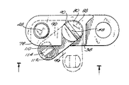
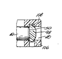
引続き図4及び図8を参照すれば、プラグ80はさらに第2の部分もしくはアーム96を具備し、アーム96はソケット54のアーム用空所76内に選択的に収容され、アーム96がチェーンピン46の軸方向の移動を制限しない第1の位置(図5)とアーム96がチェーンピン46の軸方向の移動を制限する第2の位置(図4)との間で移動可能である。アーム96は胴部84と一体で、そこから外側へ延出している。突部98がアーム96から、ヘッド86が胴部84から延出しているのと同じ方向に延出している。図8に示すように、突部98は頂面100、一対の直線状のエッジ102と104、及び一対の湾曲したエッジ106と108を有する。頂面100は、湾曲エッジ106と108に隣接した一対の面取り部分110と112、及びこれら面取り部分110と112の間の矩形部分114を有する。突部98は、アーム96をアーム用空所76内に解除可能に位置決めする手段を構成している。
【0020】
プラグ80は図4、図5及び図7を参照して以下説明するように、モジュール12内に挿入可能である。まず弾性脚92を先端とし、軸82が第1の入口60を介して、チェーンピン46の軸48と平行な方向に軸用空所56内に移動される。プラグ80を軸用空所56内へさらに移動すると、弾性脚92が壁68の外側面70と接触して内方に変形し、肩94が開口74を通ってスライド可能となる。肩94が開口74を通過し、軸用空所56の脚部分66内に至ると、脚92は最初の姿勢に戻り外方へバネ反発して開く。この位置で、肩94は壁68の内側面72と接触し、肩94が開口74を通って戻るのを壁68が防ぎ、プラグ80をソケット54内に保持してスナップ嵌合をもたらす。プラグ80はそれを一旦上記の位置に配置した後はモジュール12から取り外すように設計されていないので、この第1のスナップ嵌合は永久的なものとなる。さらに上記の位置において、ヘッド86はモジュール12の端16と面一となり、胴部84は壁68の外側面70と接触し、プラグ80がモジュール12の内部へさらに移動するのを禁止する。図5に想像線で示すように、アーム96はその第1の位置にあるとき、軸用空所56の第2の入口62を満たしてチェーンピン46の軸方向の移動を制限せず、チェーンピン46はプラグ80と干渉することなく、リンク端24の同軸方向に一致した開口30に対して挿入あるいは取り外し可能である。
【0021】
コンベヤが動作時にあるときなど、チェーンピン46の軸方向の移動を制限する必要があるときは、アーム96が以下のように第2の位置へと移動される。図5を参照すれば、溝付きネジ回しなどの工具をヘッド86のスロット90内に挿入して回転し、プラグ80が軸用空所56の軸58を中心に旋回可能となる。プラグ80は一方向においてのみ回転可能である。これは、成端リンク端32の端壁38がプラグ80の他方向における回転を禁止しているからである。プラグ80がソケット54内で旋回するにつれ、アーム96は入口78を介してアーム用空所76内に進入し、突部98の頂面100の矩形部分114が成端リンク端32の外側部分34と接触し、その外側部分34を外方に変形させる。この外方への変形により、突部98が外側部分34を通り過ぎるまでアーム96はアーム用空所76内へさらに進入可能となり、外側部分34が通常の姿勢に戻ることによって、図4に示すように第2のスナップ嵌合を与える。図3、図4及び図6に示したこの第2の位置では、アーム96がアーム用空所76内に挿入され、そのいずれの部分もモジュール12から外へ突出していない。アーム96が、開口30の外側部及び内側部40、42間の連通を遮っている。さらに、突部98は開口30の外側部40内へと延び、突部98の湾曲エッジ106と108が環状の壁44と接触することで、アーム用空所76から外れようとするアーム96の旋回移動を制限する。この第2の位置では、アーム96がチェーンピン46の一端50の軸方向の移動も制限している。また図1及び図2に示すように、モジュール12の他端18側で第2の位置にある別のプラグ80が、チェーンピン46の他端52の軸方向の移動を制限している。コンベヤチェーンアセンブリの各列が1つより多いモジュール12を含む場合、プラグ80は列の両端を形成するモジュール12のソケット内にだけ挿入される。つまりいずれの列構成についても、列毎に2つだけのプラグ80が使われる。
【0022】
第2のスナップ嵌合は係合の離脱が可能であって、永久的なものでない。チェーンピンへアクセスしたりあるいはそれを取り外したいときは、プラグ80をモジュールから取り外すのでなく、アーム96が前述した第1の位置へと戻るようにプラグを旋回すればよい。つまり、溝付きネジ回しをヘッド86のスロット90内に挿入して回転し、プラグ80を旋回させる。プラグ80が旋回するにつれ、突部98の面取り部分112が成端リンク端32の外側部分34を外方に変形させる結果、アーム96は外側部分34を通り過ぎ可能となり、プラグ80がチェーンピン46の軸方向の移動を制限しない第1の位置へ復帰可能となる。
【0023】
プラグ80は軸用空所56内に一旦挿入され固定されると、モジュール12から取り外しできないように設計されている。しかし、プラグ80をモジュール12から取り外すことはできないが、それでもチェーンピン64は取り外しあるいはその移動が制限可能である。本発明によれば、列のどちらの端からもプラグ80を介して各チェーンピン46へアクセス可能である。プラグ80がチェーンピン46の軸方向の移動を制限しているときには、前記した2つのスナップ嵌合によりプラグ80がモジュール12から外れて飛び出る可能性が減じられているので、プラグ80はモジュール12内により確実に位置される。すなわち、アーム96がプラグ80に対して追加の負荷担持容量を与える。コンベヤチェーンアセンブリ10の理想的な動作において、アーム96は大きな負荷を担う必要がない。しかし、製品がコンベヤチェーンアセンブリ10の片側に通されたり、あるいはコンベヤチェーンアセンブリ10自体が不整合であると、リンク端24において不均等な負荷の分布が発生する。この不均等な負荷がチェーンピン46に伝達され、不均等な負荷の軸方向成分がチェーンピン46をモジュール12の片側に押し出そうとする可能性がある。アーム96はチェーンピン46の軸48と直交しているので、チェーンピン46は上記の軸方向の力により、プラグ80より詳しくはアーム96の突部98を所定の位置にロックするようにアーム96と係合し、チェーンピン46の軸方向の負荷を成端リンク端32に対してよりいっそう分布させる。かかる力の伝達の結果、プラグ80はユーザに対してより高いレベルの信頼性を与えながら、よりきびしい状況において動作可能となる。
【0024】
また、アーム96がアーム用空所76内にあり且つヘッド86がモジュール12の端16と面一なので、プラグ80はモジュール12より外側へ突出しない。このようなプラグ80の配置により、コンベヤチェーンアセンブリ10の上面は変更されず、ガイドの必要やジャム停止の恐れを伴わずに、複数の独立したコンベヤチェーンが等しいあるいは異なる速度で相互に隣合って走行可能となる。複数のコンベヤチェーンを密に近接させて走行させることは、製品の取り扱いとコンベヤチェーン上への及びそこからの製品の移送を向上させる。
【0025】
図9−図18には、コンベヤチェーン10が潜在的に使用可能で、本発明を実施した物品コンベヤ装置200が示してある。図9に示すように、コンベヤ装置200はフレーム202を具備し、図示の実施例においてフレーム202は一対の直交配置されたフレーム部204と206を含む。各々のフレーム部204と206は、一組のフレームレール208、210及び212を具備する。また各々のフレーム部204と206は、テールスプロケット214(フレーム部204についてだけ概略的に示してある)とヘッドスプロケット228(フレーム部206についてだけ概略的に示してある)も具備し、これらのうち一方が駆動スプロケットとして作用する。
【0026】
コンベヤ装置200はフレーム部204上に支持され、矢印218の方向に (すなわち図9の用紙の最上部へ向かって)走行する送り込みもしくは上流側コンベヤ216も具備している。図9に示した実施例において、上流側コンベヤ216は、フレーム部204のテールスプロケット214(及びヘッドスプロケット)の周囲に架け渡されたエンドレスループを形成する。このエンドレスループの上方走行部がほぼ平面状の物品支持面224を与え、上方走行部の下面がフレーム部204のフレームレール208、210及び212によって支持されている。
【0027】
またコンベヤ装置200は、上流側コンベヤ216と交差して配置され、矢印222の方向に(すなわち図9中右方に向かって)走行するように支持された送り出しもしくは下流側コンベヤ220も具備している。下流側コンベヤ220もエンドレスループを形成し、このエンドレスループの上方走行部が上流側コンベヤ216の物品支持面224ほぼ同一平面の物品支持面226を有する。上方走行部の下面がフレーム部206のフレームレール208、210及び212によって支持され、下流側コンベヤ220はフレーム部206のヘッドスプロケット228(及びテールスプロケット)の周囲に架け渡されている。下流側コンベヤ220は、フレーム部206のヘッドスプロケット228の周囲に弧状路を形成する(図10参照)移行部230も含んでいる。移行部230と上流側コンベヤ216の側面が、図9中参照番号232で示す隙間によって分離されている。
【0028】
図面に示した特定の実施例において、上流側及び下流側コンベヤ216、220は共に、図1−図8に示したコンベヤチェーン10を変更したものである。すなわち、上流側及び下流側コンベヤ216、220は各々、横断方向に2つづつ(望ましければそれより多く)配置されたチェーンモジュール12で構成されている。各列のチェーンモジュール12を相互に接続するため、ピン46はチェーンの全幅にわたって延びたより長いチェーンピン234(図9に隠れ線として示す)で置き換えられている。この構成において、プラグ80は各列の外側でだけ用いられている。
【0029】
コンベヤ装置200はさらに、上流側及び下流側コンベヤ216と220間に位置し、両コンベヤ間で搬送物品238を移送するための移送機構236を具備している。図面に示した実施例において、移送機構236は一組のガイドレール240と242などの方向変更手段を含む。ガイドレール240と242は上流側及び下流側コンベヤ216と220の物品支持面224と226上に延び、上流側コンベヤ216上の物品238を下流側コンベヤ220へと差し向ける。上流側及び下流側コンベヤ216と220の向きが逆になったら、ガイドレール240と242はコンベヤ220からコンベヤ216へ物品を移送するように機能する。
【0030】
移送機構236は、搬送物品238を上流側コンベヤ216から下流側コンベヤ220へ隙間232を横切って搬送するための移送補助コンベヤ244も含んでいる。図9に示すように、移送補助コンベヤ244は上流側コンベヤ216と並置して平行に位置され、上流側コンベヤ216と同じ方向に走行する。移送補助コンベヤ244は、フレーム部204のテールスプロケット214とフレーム部204にその一部として支持された補助スプロケット246(図9に概略的に示す)にわたって架け渡されたエンドレスループを形成するのが好ましい。上流側コンベヤ216と移送補助コンベヤ244は共通の駆動軸(すなわちスプロケット214)を共有するのが好ましいが、その他の構成としてそれらのコンベヤを別々に駆動することもできる。これらその他の構成では、図示の実施例においてスプロケット箇所214に一致して支持された両コンベヤ216と244の端を一致させる必要はない。
【0031】
移送補助コンベヤ244は、上流側及び下流側コンベヤ216と220の物品支持面224及び226と同一平面の物品支持面250を具備する。また移送補助コンベヤ244は、横方向に離間した端部252と254も具備している。物品支持面224と250がほぼ連続状となるように、端部252が上流側コンベヤ216と当接あるいは密に隣接する一方、端部254は下流側コンベヤ220の移行部230の上方に張り出している。端部254は移送プレートとして作用し、物品支持面250と226間において滑らかな移行を与える。
【0032】
より詳しく説明すれば、図示の構成において移送補助コンベヤ244は、各々縦中心線258を有する複数のチェーンリンク256を具備したチェーンとして構成されている。各チェーンリンク256は2部片式の型成形プラスチック製であるのが好ましく、縦方向軸262を有するリンクモジュール260からなる第1の部片を含む。図示の実施例(図11及び図12参照)において、各リンクモジュール260はその軸262を中心として平面及び底面において対称的である。またリンクモジュール260はチェーンモジュール12より狭いが、その他の点ではチェーンモジュールと同様であるのが好ましく、従って上述したチェーンモジュール12より簡単に以下説明する。
【0033】
図11及び図12に示すように、各リンクモジュール260は上面266を有する中間部264を具備し(図11)、この上面266が物品支持面250の平面状部を画成している。また各リンクモジュール260は、中間部264から突出すると共に、先行及び後続それぞれのリンクモジュール260のリンク端268を噛み合う(図9参照)複数のリンク端268を具備する。各リンクモジュール260の横方向に離間した両側に位置する最外もしくは成端リンク端268に、図示の構成ではソケット54である取付孔が設けられている。
【0034】
リンクモジュール260を連続的に相互接続するため、相互に噛み合わされたリンク端268にチェーンピン270が通される。ピン270はチェーンリンク256の幅寸法よりも短く(図9参照)、移送補助コンベヤ244の動作と干渉しないように両端の最外リンク端268の間に閉じ込められている。ピン270がリンクモジュール260から外れないように、プラグ80が移送補助コンベヤ244の片側(図9における左側)でソケット54内に挿入されている。移送補助コンベヤ244の反対側のソケット54も、以下に論じる手段によって同様に塞がれる。
【0035】
各々のチェーンリンク256は、以下さらに説明するようにリンクモジュール260に対して片持ち式に固定可能な取付体272からなる第2の部片も含んでいる。取付体272は各チェーンリンク256に、平面及び底面両図においてそのチェーンリンク256の軸262及び全体の中心線258に関して非対称の外観を与える(図11及び図12参照)。また、取付体272を装着することで、ピン270は移送補助コンベヤ244の第1端部252の方に向かって片寄らされる。
【0036】
図14、図17及び図18に示すように、各取付体272は側板274と頂板276を具備し、頂板276は平面状の上面278を含んでいる。取付体272がリンクモジュール260に装着されたとき、上面278が物品支持面250の片持ち式横方向延出部280を形成し(図9、図10及び図13)、この延出部280は移行部230及び下流側コンベヤ220のヘッドスプロケット228の上方に張り出している。各々の頂板276はリンク端を持たず、当業者にとっては以下明らかになるであろう理由から、取付体272はリンクモジュール260に対して操作可能である。代わりに、各頂板276は相補的な関係にある前縁282と後縁284を備えており、延出部280が顕著な不連続性を持たないように、隣接する取付体272の対応する構造と一部重複している。
【0037】
また各々の取付体272は、頂板276の下側に一対の補強材もしくは繋部材286を具備している。物品支持面250と226間の隙間を最小限とするため、
各々の繋部材286は移行部230の弧状経路に倣うように輪郭形成された弧状の下縁288を有する(図10参照)。このように輪郭形成された下縁288を用いることで、取付体272は下流側コンベヤ220により接近して位置可能となる。
【0038】
各々の取付体272はさらに、それ自体をリンクモジュール260の1つに装着するための手段も備えている。図示の実施例において、取付体272をリンクモジュール260に装着するための手段は、保持プラグ80を変更したものであるプラグ部分290を具備する。従って、プラグ部分290と保持プラグ80に共通な要素には同じ参照番号が使われており、両プラグ間で異なる構造と動作についてだけ以下詳しく説明する。
【0039】
図14−図18に示すように、プラグ部分290は、側板274と一体でそこから延出し且つ脚92を含む主スナップ嵌合構成を支持する軸294を具備している。プラグ80をネジ回しで旋回するのを容易とするネジ回し用スロット90と異なり、軸294(及び取付体272の残部)は頂板276をつかみ回すことで、手操作により旋回可能である。プラグ部分290では、前記の突部98も、プラグ部分290のアーム96の両側からそれぞれ延出した一対の突部296と298及び側板274から延出した第3の突部300を含む副スナップ嵌合構成295で置き換えられている。突部296、298及び300は下方且つ外側に傾斜した外面302、304及び306をそれぞれ具備し、突部296、298及び300の各下方部が上方部より幅広になるようになっている。図16に示すように、プラグ部分290のアーム96がチェーンピンの移動を阻止する位置にあるとき、突部298と300はソケット54の外側部40の対向する両側内へ延出する一方、突部296はソケット54の内側部42内へ延出している。複数の突部296、298及び300を用いたこと及びこれらの突部を上記のような形状にしたことによって、突部がソケット54からより外れにくくなり、取付体272はプラグ部分290をプラグ80で取り替えた場合よりもしっかりと所定の位置に保持される。
【0040】
動作時、上流側コンベヤ216上を走行してきた物品238は、突き当りターン部に進入してガイドレール240と接触し、物品238はこのガイドレール240により、上流側コンベヤ216の方向には減速され、下流側コンベヤ220の方向には加速される。そして向きを変えながら上流側コンベヤ216を横切ると、物品238は移送補助コンベヤ244上へ移動し、今度はこのコンベヤ244が物品238を隙間232上を経て下流側コンベヤ220上へと滑らかに載置する。移送補助コンベヤ244は上流側コンベヤ216と共に走行しているので、移送補助コンベヤ244はコンベヤ走行域の終端においてその上の物品を自動的に一掃している。
本発明の各種特徴は、特許請求の範囲の各項に記載されている。
【0041】
【発明の効果】
本発明によると、交差配置されたコンベヤベルト間で搬送物品を滑らかに移送する機構を具備した搬送装置を提供することができる。
また、単一コンベヤにおける従来の移送補助コンベヤ及び静止移送プレートの各利点を組み合わせたものであり、後続の物品によって押されないと搬送物品がその上で止まってしまう可能性のある静止移送プレートと異なり、自己一掃能力を与えるようにダイナミックに動作するので、交差配置されたコンベヤチェーン間で搬送されるべき特定の搬送走行域における最後の1つまたは複数の物品を、静止移送プレートを用いた場合にしばしば見られるように、手作業で一掃する必要がない。
さらに、大ピッチを有するコンベヤチェーンで容易に使用可能であり、用途によってはより高価な小ピッチのコンベヤチェーンを用いる必要がなくなる。
【図面の簡単な説明】
【図1】コンベヤチェーンの一部の平面図。
【図2】図1に示したコンベヤチェーンの底面図。
【図3】図1に示したコンベヤチェーンの一部の拡大端面図で、チェーンピン阻止位置にあるプラグのアームを備えたチェーンモジュールの端部を含む。
【図4】図3の4−4線に沿った図で、図解のため一部が破断してある。
【図5】図3と同様の図で、第1の位置にあるプラグのアームを示す。
【図6】図3の6−6線に沿った部分側面図。
【図7】図5の7−7線に沿った図で、図解のため一部が破断してある。
【図8】プラグの斜視図。
【図9】本発明を実施した物品移送機構を含むコンベヤ装置の一部の部分概略平面図。
【図10】図9の10−10線に沿った拡大図。
【図11】図9に示した物品移送機構で使われるチェーンリンクの拡大斜視図。
【図12】図11に示したチェーンリンクの底面図。
【図13】図9に示した物品移送機構の一部の拡大図。
【図14】図13に示したチェーンリンクの一部のさらに拡大した部分概略図。
【図15】図14の15−15線に沿った拡大図。
【図16】図14の16−16線に沿った拡大図。
【図17】図14に示した片持ち式取付具の斜視図。
【図18】図17に示した片持ち式取付具の拡大端面図。
【符号の説明】
16,18 リンク(チェーン)モジュール(部分)12,260の一対の端部
54 取付孔(ソケット)
92 主スナップ嵌合構成(脚)
96 アーム
200 コンベヤ(物品搬送)装置
202 フレーム
208 (ヘッド)スプロケット
216 コンベヤチェーン(上流側コンベヤ)
220 下流側コンベヤ
224、226、250 物品支持面
230 移行部
238 物品
244 移送補助コンベヤ
252 リンクモジュール(部分)260の他方の端部で16に対応
254 移送プレート(移送補助コンベヤ端部)
256 チェーンリンク
260 リンクモジュール(部分)
262 リンクモジュール部分の縦方向軸
268 リンク端
270 チェーンピン
272 第2の部分(取付体)
276 頂板
278 平面状表面(上面)
280 片持ち式横方向延出部
288 弧状下縁(部)
290 プラグ部分(装着手段)
295(296、298、300) 副スナップ嵌合構成(突部)[0001]
[Industrial application fields]
The present invention relates generally to article transport devices, and more particularly to a mechanism for transporting articles between crossed conveyor belts or chains.
[0002]
[Prior art]
Transport equipment is used in various manufacturing, processing and other processes for transporting articles. Known conveying equipment comprises a conveyor chain, which is composed of chain links or modules interconnected by chain pins and is supported on a conveyor frame that defines the path of goods to be conveyed.
[0003]
When it is desired to convey an article along a non-linear path, it is known to use a side-curved conveyor chain. Examples of chain links used in side curved conveyor chains are disclosed in US Pat. Nos. 4,893,709 and 4,436,200. When a wider conveying surface or higher load carrying capacity is desired, a linear travel conveyor chain is often preferred over a side curved conveyor chain. Examples of chain links used in linear travel conveyor chains are US Pat. Nos. 5,215,185, 5,125,504 and 4,858,753, US Design Patents 270,201 and No. 270,202.
[0004]
[Problems to be solved by the invention]
In order to form a non-linear conveyor path with a straight traveling conveyor chain, the chains are arranged so as to cross each other, and an article transfer mechanism is provided at the crossing position between the two conveyor chains. Transport the goods. If the article to be conveyed is difficult to tip over and is large enough not to fall between crossed conveyor chains, the transfer mechanism need only comprise guide rails for changing the direction of the article path. For example, a short article with a large “footprint” may require a structure with a small pitch (ie, approximately equal) arranged in an orthogonal arrangement without the need for a structure to prevent the article from falling through the gap between conveyor chains. Often transported between conveyor chains (having a pitch of less than 1 inch). In other applications, mechanisms such as stationary transfer plates and transfer assist conveyor chains are used in combination with guide rails to transfer articles between conveyor chains.
[0005]
An example of a conveying device using a guide rail, a stationary transfer plate and a narrow transfer auxiliary conveyor chain in a 90-degree turn portion or “butt corner” between crossed upstream and downstream conveyors is disclosed in US Pat. No. 167,319. In this US patent, a transfer plate extends along the side of the upstream conveyor in the gap between the upstream and downstream conveyors. A transfer auxiliary chain is then placed along the side of the downstream conveyor at the butt corner to fill the transition area defined by the guide rail. Alternatively, the transfer assist chain can be arranged along the side of the upstream conveyor.
[0006]
[Means for Solving the Problems]
The present invention provides a transport device with an improved mechanism for transporting transported articles between crossed conveyor belts. The improved transfer mechanism combines the advantages of conventional transfer assist conveyors and stationary transfer plates on a single conveyor. Unlike a stationary transfer plate, where the transported article may stop on it if not pushed by a subsequent article, the improved transfer mechanism operates dynamically to provide self-cleaning capability. This means that the last article or articles in a particular transport area to be transported between crossed conveyor chains need to be manually cleared, as is often the case with stationary transfer plates There is no. Furthermore, the improved transfer mechanism can be readily used with conveyor chains having a large pitch (ie, about 1 inch or greater), eliminating the need for more expensive small pitch conveyor chains in some applications.
[0007]
More particularly, the present invention provides a conveyor apparatus with both upstream and downstream conveyors arranged in a cross-position, in one embodiment arranged at right angles to form a butt turn. The conveyor device also includes an article transfer mechanism that redirects articles from the upstream conveyor to the downstream conveyor. The transfer mechanism includes a guide rail for changing the direction of the conveyed article, and a transfer auxiliary conveyor that is positioned between both the upstream and downstream conveyors and transfers the conveyed article between the two.
[0008]
The transfer assist conveyor preferably travels at the same speed parallel to one of the upstream and downstream conveyors, with one side of the transfer assist conveyor being closely adjacent to or abutting the one conveyor. The other side of the transfer auxiliary conveyor is cantilevered above the other sprocket position of both the upstream and downstream conveyors and acts as a transfer plate to substantially fill the gap between the conveyors. In one embodiment, the transfer assist conveyor is a chain that includes a plurality of chain links interconnected by pins. Each chain link includes a link module made of molded plastic that meshes with another link module, and a mounting body that can be mounted in a cantilever manner on one side of the link module.
[0009]
In one embodiment, the present invention also provides a conveyor apparatus comprising a first conveyor having an article support surface and a transition located at a sprocket location and deviating from the plane of the article support surface. The conveyor apparatus also includes a second conveyor that is disposed intersecting the first conveyor. The second conveyor comprises a plurality of chain links having link module portions interconnected by chain pins. The link module portion has upper surfaces that form an article support surface on a second conveyor that is coplanar with the article support surface of the first conveyor. The chain link also includes a cantilever portion that extends laterally from the link module portion to provide an extension of the article support surface of the second conveyor. This extension overhangs above the transition of the first conveyor and acts as a moving transfer plate for smooth transfer of conveyed articles between the first and second conveyors.
[0010]
The present invention further provides a conveyor apparatus comprising first and second conveyors that are supported together on a frame and each have an article support surface arranged in a cross-position. The conveyor device also includes means for transporting transported articles from the first conveyor to the second conveyor. In one embodiment, the transport means includes a transfer assist conveyor supported on the frame in a relationship intersecting the second conveyor in a side-by-side relationship with the first conveyor. The transfer assist conveyor preferably includes an article support surface that is coplanar with the article support surfaces of the first and second conveyors, and the transfer assist conveyor is preferably formed as a chain that includes a plurality of interconnected chain links. . Each chain link includes a link module portion and a cantilever portion extending laterally therefrom. The cantilevered portions of these chain links form an extension of the article support surface of the transfer assist conveyor that protrudes above the second conveyor.
Other features and advantages of the present invention will become apparent to those skilled in the art upon review of the following description, appended claims, and accompanying drawings.
[0011]
【Example】
Before describing in detail one embodiment of the present invention, it is to be understood that the application of the present invention is not limited to the details of construction and the arrangement of components shown in the following description or the accompanying drawings. The present invention can be implemented in other ways than illustrated, and can be used and implemented in various ways. Also, the expressions and terms used herein are for illustrative purposes and should not be construed as limiting.
[0012]
A conveyor chain assembly 10 including multiple rows of
[0013]
The link ends 24 of either the first set 26 or the second set 28 include special link ends or terminated link ends 32 that form the ends 16 and 18 of the
[0014]
The link end 24 of each
[0016]
With continued reference to FIGS. 1 and 2,
[0017]
Socket 54 further includes an
[0018]
As shown in FIGS. 4 and 8, a chain pin holding plug 80 can be mounted on the
[0019]
Still referring to FIGS. 4 and 8, the plug 80 further includes a second portion or
[0020]
The plug 80 can be inserted into the
[0021]
When it is necessary to limit the axial movement of the chain pin 46, such as when the conveyor is in operation, the
[0022]
The second snap fit can be disengaged and is not permanent. When it is desired to access or remove the chain pin, the plug may be pivoted so that the
[0023]
The plug 80 is designed so that it cannot be removed from the
[0024]
Also, since the
[0025]
9-18 illustrate an article conveyor apparatus 200 in which the conveyor chain 10 is potentially usable and the present invention is implemented. As shown in FIG. 9, the conveyor apparatus 200 includes a frame 202, which in the illustrated embodiment includes a pair of orthogonally disposed
[0026]
Conveyor device 200 is also supported on frame portion 204 and also includes an infeed or upstream conveyor 216 that travels in the direction of arrow 218 (ie, toward the top of the paper in FIG. 9). In the embodiment shown in FIG. 9, the upstream conveyor 216 forms an endless loop that extends around the tail sprocket 214 (and head sprocket) of the frame portion 204. The upper traveling portion of the endless loop provides a substantially flat
[0027]
The conveyor apparatus 200 also includes a delivery or downstream conveyor 220 that is disposed across the upstream conveyor 216 and is supported to travel in the direction of arrow 222 (ie, toward the right in FIG. 9). Yes. The downstream conveyor 220 also forms an endless loop, and the upper running portion of the endless loop has an article support surface 226 that is substantially flush with the
[0028]
In the particular embodiment shown in the drawings, both upstream and downstream conveyors 216, 220 are modifications of the conveyor chain 10 shown in FIGS. That is, the upstream and downstream conveyors 216, 220 are each composed of
[0029]
The conveyor apparatus 200 further includes a transfer mechanism 236 located between the upstream and downstream conveyors 216 and 220 for transferring the conveyed
[0030]
The transfer mechanism 236 also includes a transfer assist conveyor 244 for transferring the conveyed
[0031]
The transfer assist conveyor 244 includes an
[0032]
More specifically, in the illustrated configuration, the transfer assist conveyor 244 is configured as a chain having a plurality of
[0033]
As shown in FIGS. 11 and 12, each
[0034]
In order to continuously interconnect the
[0035]
Each chain link 256 also includes a second piece of
[0036]
As shown in FIGS. 14, 17, and 18, each mounting
[0037]
Each mounting
Each connecting member 286 has an arcuate lower edge 288 that is contoured to follow the arcuate path of the transition 230 (see FIG. 10). Using the contoured lower edge 288, the
[0038]
Each
[0039]
As shown in FIGS. 14-18, the plug portion 290 includes a
[0040]
In operation, the
Various features of the invention are set forth in the claims.
[0041]
【The invention's effect】
ADVANTAGE OF THE INVENTION According to this invention, the conveying apparatus provided with the mechanism in which a conveyed article is smoothly transferred between the conveyor belts which cross-arranged can be provided.
In addition, it combines the advantages of the conventional transfer auxiliary conveyor and stationary transfer plate in a single conveyor, unlike the stationary transfer plate where the transported article may stop on it if not pushed by the subsequent article. Since it operates dynamically to provide self-cleaning capability, the last one or more articles in a particular transport range to be transported between crossed conveyor chains can be used when stationary transfer plates are used. As is often seen, there is no need to manually wipe out.
Furthermore, it can be easily used with a conveyor chain having a large pitch, and depending on the application, it is not necessary to use a more expensive small pitch conveyor chain.
[Brief description of the drawings]
FIG. 1 is a plan view of a part of a conveyor chain.
FIG. 2 is a bottom view of the conveyor chain shown in FIG.
FIG. 3 is an enlarged end view of a portion of the conveyor chain shown in FIG. 1 including the end of a chain module with an arm of a plug in a chain pin blocking position.
4 is a view taken along line 4-4 of FIG. 3 and is partially broken for illustration.
FIG. 5 is a view similar to FIG. 3, showing the arm of the plug in the first position.
6 is a partial side view taken along line 6-6 in FIG. 3;
7 is a view taken along line 7-7 in FIG. 5 and is partially broken for illustration.
FIG. 8 is a perspective view of a plug.
FIG. 9 is a partial schematic plan view of a part of a conveyor apparatus including an article transfer mechanism embodying the present invention.
10 is an enlarged view taken along line 10-10 in FIG.
11 is an enlarged perspective view of a chain link used in the article transfer mechanism shown in FIG.
12 is a bottom view of the chain link shown in FIG.
13 is an enlarged view of a part of the article transfer mechanism shown in FIG.
14 is a further enlarged partial schematic view of a part of the chain link shown in FIG. 13;
15 is an enlarged view taken along the line 15-15 in FIG. 14;
16 is an enlarged view taken along the line 16-16 in FIG. 14;
17 is a perspective view of the cantilevered fixture shown in FIG. 14. FIG.
18 is an enlarged end view of the cantilevered fixture shown in FIG.
[Explanation of symbols]
16, 18 A pair of ends of link (chain) module (part) 12, 260
54 Mounting hole (socket)
92 Main snap fitting configuration (leg)
96 arms
200 Conveyor equipment
202 frames
208 (head) sprocket
216 Conveyor chain (upstream conveyor)
220 Downstream conveyor
224, 226, 250 Article support surface
230 Transition Department
238 articles
244 Transfer assist conveyor
252 Supports 16 at the other end of the link module (part) 260
254 Transfer plate (end of transfer auxiliary conveyor)
256 chain link
260 Link module (part)
262 Longitudinal axis of the link module part
268 Link end
270 chain pin
272 Second part (mounting body)
276 Top plate
278 Planar surface (upper surface)
280 Cantilevered lateral extension
288 Arc-shaped lower edge (part)
290 Plug part (mounting means)
295 (296, 298, 300) Sub-snap fitting configuration (protrusion)
Claims (11)
両側部を有し、コンベヤチェーンの移動方向に沿って両側部間に延びる幅寸法を有し、
コンベヤを構成する複数のチェーンリンクを備え、該チェーンリンクの各々が、
横方向に離間した両側縁と、これら両側縁間の物品支持面領域とを具備するリンクモ ジュール部分、
前記リンクモジュール部分に対して片持ち状で、コンベヤチェーンの移動方向に対し て横方向に延びた第2の部分で、前記リンクモジュール部分の両側縁の一方に固定 可能である交換可能な取付体を具備した第2の部分、及び
複数の細長いチェーンピンを備え、各チェーンピンが、
両端、及び
前記幅寸法より小さい両端間の長さを有しており、前記第2の部分が前記チェーン ピン両端の一方に対しずれた位置関係で片持ち支持されるように側方にずらして 配置されると共に、前記各物品支持面が連続状の物品支持面を形成するように前 記リンクモジュール部分を連続的に相互連結している、
コンベヤチェーン。In the conveyor chain,
Having both sides and having a width dimension extending between both sides along the direction of movement of the conveyor chain;
A plurality of chain links constituting a conveyor, each of the chain links,
A link module portion having laterally spaced side edges and an article support surface area between the side edges;
A replaceable mounting body that is cantilevered with respect to the link module part and extends in a direction transverse to the moving direction of the conveyor chain and can be fixed to one of both side edges of the link module part. And a plurality of elongated chain pins, each chain pin comprising:
Both ends, and having a length between both ends smaller than the width dimension, and the second portion is shifted laterally so that it is cantilevered with a positional relationship shifted with respect to one of both ends of the chain pin. And the link module parts are continuously interconnected so that each article support surface forms a continuous article support surface.
Conveyor chain.
前記交換可能な取付体は前記物品支持面領域と同一面の関係にある平面状表面を具備 し、
前記交換可能な取付体は、前記平面状表面が前記コンベヤと交差配置された第2のコンベヤの一部の上方へ延び、物品を両コンベヤ間で移送するように構成および配置されているコンベヤチェーン。The conveyor chain according to claim 2,
The replaceable attachment body comprises a planar surface that is coplanar with the article support surface region,
The interchangeable attachment includes a conveyor chain configured and arranged to extend above a portion of a second conveyor, the planar surface intersecting the conveyor, to transfer articles between the two conveyors. .
前記一方のコンベヤと交差配置された他方のコンベヤを備え、該他方のコンベヤが、
複数の細長いチェーンピン、及び
前記チェーンピンによって相互に連結された複数のチェーンリンクを備え、各チェー ンリンクが、
横方向に離間した両側部で、前記チェーンピンを両側部間に全体的に内包する両 側部と、
前記一方のコンベヤの前記物品支持面とほぼ同一面上の物品支持面とを具備する リンクモジュール部分、及び
前記チェーンピンからずれて前記リンクモジュール部分に対して横方向に、前記 一方のコンベヤの前記移送部の上方に張り出すように延びて前記他方のコンベ ヤの物品支持面の延出部を与えると共に、前記リンクモジュール部分の横方向 に離間した側部の一方に固定可能である交換可能な取付体を具備する片持ち状 部を有している、
コンベヤ装置。One conveyor comprising an article support surface defining a plane, and a transfer section deviating downward from the plane, and the other conveyor crossed with the one conveyor, the other conveyor comprising:
A plurality of elongate chain pins and a plurality of chain links interconnected by the chain pins, each chain link comprising:
On both sides spaced apart in the lateral direction, both sides that totally enclose the chain pin between the sides,
A link module part comprising an article support surface substantially flush with the article support surface of the one conveyor, and laterally relative to the link module part offset from the chain pin, the one of the conveyors An exchangeable extension that extends over the transfer section to provide an extension of the article support surface of the other conveyor and can be secured to one of the laterally spaced sides of the link module portion Having a cantilevered portion with a mounting body,
Conveyor device.
フレーム、flame,
前記フレーム上に支持され、物品支持面を含む第1のコンベヤ、A first conveyor supported on the frame and including an article support surface;
前記第1コンベヤと交差配置され、前記フレーム上に支持され、物品支持面を含む第2A second crossing with the first conveyor, supported on the frame and including an article support surface のコンベヤ、及びConveyors, and
前記フレーム上に前記第1及び第2コンベヤの一方と並列状に支持され、前記第1及びSupported in parallel with one of the first and second conveyors on the frame; 第2コンベヤの他方と交差して延びる移送補助コンベヤチェーン、A transfer auxiliary conveyor chain extending across the other of the second conveyor;
を備え、該移送補助コンベヤチェーンが、The transfer auxiliary conveyor chain comprises:
前記第1及び第2コンベヤの前記物品支持面と同一面上の物品支持面と、An article support surface on the same plane as the article support surfaces of the first and second conveyors;
複数の相互に連結された複数のチェーンリンクとを備え、A plurality of interconnected chain links,
各チェーンリンクの各々が、Each chain link
横方向に離間した両側部を具備し、これら両側部の一方が前記第1及び第2コンBoth side portions spaced apart in the lateral direction are provided, and one of the both side portions is the first and second connectors. ベヤの前記一方に沿って延び、前記横方向に離間した両側部の他方が取付孔をThe other of the laterally spaced side portions that extend along the one side of the bearer has a mounting hole. 有するリンクモジュール部分、及びA link module part having, and
前記リンクモジュール部分に対して横方向に延びた片持ち状部で、前記第1及びA cantilever extending laterally with respect to the link module portion, the first and 第2コンベヤの他方の上方に張り出た前記移送補助コンベヤチェーンの物品支Article support of the transfer auxiliary conveyor chain overhanging the other side of the second conveyor 持面の延出部を与えると共に、前記リンクモジュール部分の1つの前記取付孔One extension hole of the link module part, while providing an extension part of the holding surface に固定可能である交換可能な取付体を具備した片持ち状部を有している、Having a cantilevered portion with a replaceable attachment that is fixable to
コンベヤ装置。Conveyor device.
前記ソケット内に受け入れ可能で、前記取付体を前記チェーンリンクモジュールへ解放可能に固定するプラグ部分を備え、該プラグ部分がアームを具備し、A plug portion receivable in the socket and releasably securing the mounting body to the chain link module, the plug portion comprising an arm;
前記アームが、The arm is
両端部、Both ends,
前記アームの前記両端部の一方に設けられた主スナップ嵌合機構、A main snap fitting mechanism provided on one of the both ends of the arm;
前記アームの前記両端部の他方に設けられた副スナップ嵌合機構、及びA sub-snap fitting mechanism provided on the other of the both ends of the arm; and
前記プラグ部分から平行に延び、前記チェーンリンクモジュールに対して片持ち状に延びるように構成及び配置された頂板を具備している、物品移送取付体。An article transport attachment comprising a top plate configured and arranged to extend in parallel from the plug portion and cantilevered relative to the chain link module.
前記主スナップ嵌合機構は、前記取付体を前記チェーンリンクモジュールに対して旋回させるピボット点として作用し、The main snap fitting mechanism acts as a pivot point for turning the attachment body with respect to the chain link module;
前記副スナップ嵌合機構は、第1の位置と、前記チェーンリンクモジュールの1つを前記チェーンリンクモジュールの別の1つに連結するのに用いられるチェーンピンの移動を前記副スナップ嵌合機構が妨げる第2の位置との間で移動可能である物品移送取付体。The sub-snap fitting mechanism includes a first position and movement of a chain pin used to connect one of the chain link modules to another one of the chain link modules. An article transport attachment that is movable between a second position to block.
前記ソケット内に受け入れ可能で、前記取付体を前記チェーンリンクモジュールへ解放可能に固定するプラグ部分、及びA plug portion receivable within the socket and releasably securing the mounting body to the chain link module; and
前記プラグ部分から平行に延び、前記チェーンリンクモジュールに対して片持ち状に延びるように構成及び配置された頂板、A top plate configured and arranged to extend in parallel from the plug portion and cantilevered to the chain link module;
を備えた物品移送取付体。An article transfer attachment body comprising:
Applications Claiming Priority (2)
| Application Number | Priority Date | Filing Date | Title |
|---|---|---|---|
| US08/374,849 US5634550A (en) | 1993-03-12 | 1995-01-19 | Direction changing mechanism for transferring articles between transverse conveyors |
| US374,849 | 1995-01-19 |
Publications (2)
| Publication Number | Publication Date |
|---|---|
| JPH08239117A JPH08239117A (en) | 1996-09-17 |
| JP3611659B2 true JP3611659B2 (en) | 2005-01-19 |
Family
ID=23478451
Family Applications (1)
| Application Number | Title | Priority Date | Filing Date |
|---|---|---|---|
| JP02184496A Expired - Lifetime JP3611659B2 (en) | 1995-01-19 | 1996-01-12 | Direction changing mechanism for transferring articles between crossing conveyors |
Country Status (8)
| Country | Link |
|---|---|
| US (1) | US5634550A (en) |
| EP (1) | EP0722896B1 (en) |
| JP (1) | JP3611659B2 (en) |
| KR (1) | KR100347992B1 (en) |
| AU (1) | AU688057B2 (en) |
| CA (1) | CA2153467C (en) |
| DE (1) | DE69509351T2 (en) |
| DK (1) | DK0722896T3 (en) |
Families Citing this family (38)
| Publication number | Priority date | Publication date | Assignee | Title |
|---|---|---|---|---|
| US5850902A (en) * | 1995-10-06 | 1998-12-22 | The Laitram Corporation | Transferring articles from a moving belt edge onto a normally disposed moving conveyor belt |
| NL1002390C2 (en) * | 1996-02-19 | 1997-08-20 | Mcc Nederland | Transport mat built from plastic modules and modules for such a transport mat. |
| NL1002501C2 (en) * | 1996-03-01 | 1997-09-03 | Mcc Nederland | Plastic module for a transport mat. |
| US6471048B1 (en) * | 1999-03-19 | 2002-10-29 | Vic Thompson Company | Conveyor belt system |
| US6508153B1 (en) * | 2000-02-04 | 2003-01-21 | C.G. Bretting Mfg. Co., Inc. | Conveyor product transfer apparatus and method |
| US6330941B1 (en) * | 2000-05-25 | 2001-12-18 | Habasit Ag | Radius conveyor belt |
| US6305530B1 (en) | 2000-05-30 | 2001-10-23 | Habasit Ag | Module for a modular conveying belt |
| US6367619B1 (en) * | 2000-07-13 | 2002-04-09 | Rexnord Corporation | Conveyor nose bar |
| ES2173801B2 (en) * | 2000-08-01 | 2003-05-01 | Univ Madrid Politecnica | MOBILE TRANSFER ANGLE BAND BRUSH FOR PRODUCT HANDLING LINES SUSCEPTIBLE TO DAMAGES. |
| US6554129B2 (en) | 2001-03-08 | 2003-04-29 | The Laitram Corporation | Attachments in modular conveyor belts |
| US6696003B2 (en) * | 2001-05-29 | 2004-02-24 | Habasit Ag | Methods for manufacturing a module for a modular conveyor belt having a sandwich layer construction |
| US6725883B2 (en) | 2001-06-05 | 2004-04-27 | Habasit Ag | Flat top open hinge module |
| JP3513616B2 (en) | 2001-06-28 | 2004-03-31 | 山久チヱイン株式会社 | Cross conveyor chain device |
| ITMI20010599U1 (en) * | 2001-11-13 | 2003-05-13 | System Plast Spa | CHAIN CONVEYOR |
| NL1020520C2 (en) * | 2002-05-02 | 2003-11-11 | Kaak Johan H B | Conveyor belt. |
| NL1021038C2 (en) | 2002-07-09 | 2004-01-16 | Mcc Nederland | Transport system and transfer device. |
| US6999847B2 (en) * | 2002-07-26 | 2006-02-14 | Unelab Llc | Specimen carrier transfer apparatus for a conveyor track |
| ATE283219T1 (en) * | 2003-05-06 | 2004-12-15 | Meccaniche Crizaf S P A Costru | MODULAR CONVEYOR BELT WITH CROSS CONVEYOR ELEMENTS |
| DE20310360U1 (en) * | 2003-07-05 | 2003-09-11 | Schüco International KG, 33609 Bielefeld | Flat top chain with guide device |
| US6814223B1 (en) | 2003-09-25 | 2004-11-09 | Laitram, L.L.C. | Self-closing hinge rod retention in modular plastic conveyor belts |
| US7210569B1 (en) * | 2004-02-09 | 2007-05-01 | Tarpaulin.Com, Inc. | Transfer device for conveyor belt |
| US7530454B2 (en) * | 2005-11-08 | 2009-05-12 | Ashworth Bros. Inc. | Conveyor belt |
| ATE543760T1 (en) * | 2008-02-01 | 2012-02-15 | System Plast S R L | CONVEYOR BELT WITH SEVERAL HINGE MODULES AND MEANS FOR AVOIDING AXIAL DISPLACEMENT OF THE MODULE PIGS |
| US9216859B2 (en) | 2013-05-03 | 2015-12-22 | Habasit Ag | Rod retention system and method |
| NL2012375B1 (en) | 2014-03-06 | 2015-12-03 | Rexnord Flattop Europe Bv | Transfer device, conveyor system including a transfer device and method of transferring conveyed products. |
| DE102014103711A1 (en) | 2014-03-19 | 2015-09-24 | Krones Ag | Deflection device for objects and methods for deflecting objects |
| US9452896B2 (en) * | 2014-09-25 | 2016-09-27 | Laitram, L.L.C. | Pop-up conveyor transfer system |
| US9139370B1 (en) * | 2015-02-25 | 2015-09-22 | George W. Massey, Jr. | Conveyor system and a mechanical chain having a plurality of links |
| US10155625B1 (en) | 2015-09-01 | 2018-12-18 | Laitram, L.L.C. | Conveyor belts and modules with twist-lock accessories |
| CN105600417A (en) * | 2015-11-02 | 2016-05-25 | 经纬纺织机械股份有限公司 | Pushing blocking rod mechanism |
| WO2017099988A1 (en) | 2015-12-09 | 2017-06-15 | Laitram, L.L.C. | Conveyor transfer assembly |
| DE102016205304A1 (en) | 2016-03-31 | 2017-10-05 | Krones Ag | Low pressure storage device and / or distribution unit for containers |
| CA3054597A1 (en) | 2017-03-08 | 2018-09-13 | Robert D. Lundahl | Package sorting transfer module and systems and methods therefor |
| US10532894B2 (en) | 2017-03-10 | 2020-01-14 | Regal Beloit America, Inc. | Modular transfer units, systems, and methods |
| ES2684984B1 (en) | 2017-03-31 | 2019-04-04 | Afher Eurobelt S A | Transfer comb and transfer system between two belt conveyors |
| US10640303B2 (en) | 2017-11-22 | 2020-05-05 | Regal Beloit America, Inc. | Modular sortation units, systems, and methods |
| CN109607044A (en) * | 2019-01-21 | 2019-04-12 | 深圳市华南新海传动机械有限公司 | A kind of structure for conveying of slots close |
| US20240010436A1 (en) * | 2020-11-09 | 2024-01-11 | Laitram, L.L.C. | Modular conveyor belt with moveable hinge rod retainer |
Family Cites Families (36)
| Publication number | Priority date | Publication date | Assignee | Title |
|---|---|---|---|---|
| US811391A (en) * | 1903-05-14 | 1906-01-30 | William H Gates | Drive-chain. |
| US1046124A (en) * | 1911-03-13 | 1912-12-03 | John F Wagner | Drive-chain. |
| US1966659A (en) * | 1932-01-20 | 1934-07-17 | Solar Sturges Mfg Co | Conveyer chain |
| US2402376A (en) * | 1944-07-28 | 1946-06-18 | Ferdinand H Dalrymple | Conveyer chain |
| US2631465A (en) * | 1949-05-11 | 1953-03-17 | Cordis Nat | Demountable chain |
| US3062193A (en) | 1958-07-17 | 1962-11-06 | Zwicky | Hydraulic rotary-piston machines |
| US2951578A (en) * | 1959-02-11 | 1960-09-06 | Chain Belt Co | Rubber pad attachment for conveyor chain |
| US3643781A (en) * | 1970-05-27 | 1972-02-22 | Schlitz Brewing Co J | Deadplate construction for a conveyor system |
| BE795352A (en) | 1972-02-14 | 1973-05-29 | Rexnord Inc | FLAT TOP SIDE CHAIN, LOW FRICTION COEFFICIENT, FOR OBJECT HANDLING |
| US4006817A (en) * | 1972-07-07 | 1977-02-08 | Incom International Inc. | Conveyor chain |
| US3871510A (en) * | 1973-04-19 | 1975-03-18 | Fmc Corp | Magnetic conveyor structure |
| US3910406A (en) * | 1973-09-26 | 1975-10-07 | Velten & Pulver | Two-part clip |
| US5024321A (en) * | 1980-08-19 | 1991-06-18 | Laitram Corporation | Modular center drive conveyor belt |
| US4832187A (en) * | 1980-08-19 | 1989-05-23 | The Laitram Corporation | Modular center drive conveyor belt |
| US5123524A (en) * | 1980-08-19 | 1992-06-23 | The Laitram Corporation | Modular center drive conveyor belt |
| USD270202S (en) | 1980-09-18 | 1983-08-16 | Rexnord Inc. | Conveyor module |
| USD270201S (en) | 1980-09-18 | 1983-08-16 | Rexnord Inc. | Conveyor module |
| GB2089475A (en) * | 1980-12-12 | 1982-06-23 | Quality Inspection Services Lt | Rotary couplings |
| US4557374A (en) * | 1982-02-23 | 1985-12-10 | The Cambridge Wire Cloth Company | Modular conveyor belting with cam-slotted links for maintaining transverse distribution of tension while negotiating horizontal curves and for facilitating cleaning |
| DE3241632C2 (en) * | 1982-11-11 | 1986-09-25 | Draadindustrie Jonge Poerink B.V., Borne | Conveyor belt made of plastic links with inserted cross bars |
| JPS6259607U (en) * | 1985-10-03 | 1987-04-13 | ||
| US4858753A (en) * | 1987-04-15 | 1989-08-22 | Rexnord Corporation | Conveyor chain assembly |
| US5020659A (en) * | 1987-04-15 | 1991-06-04 | Rexnord Corporation | Conveyor chain assembly |
| DK159544C (en) * | 1988-04-21 | 1991-04-02 | Baeltix A S Maskinfabrikken | CHAIRLED WITH WELDING TAPES AND WELDING TAPES HERE |
| US4893709A (en) | 1988-08-18 | 1990-01-16 | Rexnord Corporation | Back-flexing article carrying chain |
| US4993544A (en) * | 1989-01-13 | 1991-02-19 | Cambridge Wire Cloth Company | Plastic modular conveyor belts and modules therefor |
| US4893710A (en) * | 1989-01-13 | 1990-01-16 | Cambridge Wire Cloth Company | Plastic modular conveyor belts and modules therefor |
| US4953693A (en) * | 1989-01-23 | 1990-09-04 | Span Tech Corporation | Modular link conveyor system |
| US5031757A (en) * | 1989-12-26 | 1991-07-16 | Span Tech Corporation | Modular link conveyor system with narrow chain |
| US5083660A (en) * | 1990-11-08 | 1992-01-28 | The Laitram Corporation | Removably retaining pivot rods in modular plastic belts |
| SE9004102D0 (en) * | 1990-12-21 | 1990-12-21 | Skf Specialty Product Ab | PLASTIC CHAIN AND INSTALLABLE LOADING LEATHER RESPECTIVE STEERING STEP |
| US5125504A (en) | 1991-03-08 | 1992-06-30 | Rexnord Corporation | Modular conveyor chain having open hinge pin construction |
| US5167319A (en) * | 1991-08-21 | 1992-12-01 | Mcmackin Jr Paul J | Direction changing conveyor |
| US5217110A (en) * | 1992-04-23 | 1993-06-08 | Cambridge Wire Cloth Company | Modular plastic turn belt conveyor system, module, belt and drive therefor |
| US5215185A (en) | 1992-09-08 | 1993-06-01 | Rexnord Corporation | Breakable molded plastic links for forming conveyor chain |
| US5335768A (en) * | 1993-03-12 | 1994-08-09 | Rexnord Corporation | Conveyor chain assembly |
-
1995
- 1995-01-19 US US08/374,849 patent/US5634550A/en not_active Expired - Lifetime
- 1995-07-07 CA CA002153467A patent/CA2153467C/en not_active Expired - Lifetime
- 1995-07-11 EP EP95304834A patent/EP0722896B1/en not_active Expired - Lifetime
- 1995-07-11 DE DE69509351T patent/DE69509351T2/en not_active Expired - Lifetime
- 1995-07-11 DK DK95304834T patent/DK0722896T3/en active
- 1995-07-28 AU AU27231/95A patent/AU688057B2/en not_active Expired
- 1995-08-23 KR KR1019950026107A patent/KR100347992B1/en not_active IP Right Cessation
-
1996
- 1996-01-12 JP JP02184496A patent/JP3611659B2/en not_active Expired - Lifetime
Also Published As
| Publication number | Publication date |
|---|---|
| CA2153467A1 (en) | 1996-07-20 |
| KR100347992B1 (en) | 2002-11-07 |
| DK0722896T3 (en) | 1999-11-01 |
| AU2723195A (en) | 1996-07-25 |
| DE69509351T2 (en) | 1999-10-14 |
| DE69509351D1 (en) | 1999-06-02 |
| US5634550A (en) | 1997-06-03 |
| CA2153467C (en) | 2006-01-10 |
| KR960029213A (en) | 1996-08-17 |
| EP0722896A1 (en) | 1996-07-24 |
| EP0722896B1 (en) | 1999-04-28 |
| AU688057B2 (en) | 1998-03-05 |
| JPH08239117A (en) | 1996-09-17 |
Similar Documents
| Publication | Publication Date | Title |
|---|---|---|
| JP3611659B2 (en) | Direction changing mechanism for transferring articles between crossing conveyors | |
| US5335768A (en) | Conveyor chain assembly | |
| US4880107A (en) | Table top chain link with rib | |
| US7331448B2 (en) | Modular conveying assembly having roller cradles | |
| EP0054394B1 (en) | Modular plastic conveyor belt | |
| CA2380127C (en) | Snap-on side guards | |
| KR100570934B1 (en) | Side Bending Conveyor | |
| US4153152A (en) | Bi-directional hinged conveyor belt | |
| EP1842806B1 (en) | Conveyor module with a snap fit extension for supporting a roller | |
| JP3513616B2 (en) | Cross conveyor chain device | |
| ZA9284B (en) | Modular conveyor chain having open hinge pin construction | |
| CA2668037A1 (en) | Conveyor belt with intermodular supported rollers | |
| DE69912274D1 (en) | Conveyor chain swivels to the side | |
| CA2261226A1 (en) | Module having a retaining member for use in a modular conveyor mat | |
| EP1666385A1 (en) | Side-flexing conveyor chain | |
| JP2007513849A (en) | Side-flexible conveyor chain with lateral twin connectors | |
| US7168557B2 (en) | Side-flexing conveyor chain having members joined by linkages | |
| EP0524543A1 (en) | Distributing transportation device | |
| US10294040B2 (en) | Split fluid jet head and manifold for receipt of split fluid jet head | |
| EP1386861A1 (en) | Device for transferring products from a first conveyor to a second conveyor | |
| DE29522127U1 (en) | Deflection device for transferring objects between cross conveyors |
Legal Events
| Date | Code | Title | Description |
|---|---|---|---|
| A02 | Decision of refusal |
Free format text: JAPANESE INTERMEDIATE CODE: A02 Effective date: 20010410 |
|
| A601 | Written request for extension of time |
Free format text: JAPANESE INTERMEDIATE CODE: A601 Effective date: 20040419 |
|
| A602 | Written permission of extension of time |
Free format text: JAPANESE INTERMEDIATE CODE: A602 Effective date: 20040426 |
|
| A521 | Request for written amendment filed |
Free format text: JAPANESE INTERMEDIATE CODE: A523 Effective date: 20040721 |
|
| A521 | Request for written amendment filed |
Free format text: JAPANESE INTERMEDIATE CODE: A523 Effective date: 20040908 |
|
| A61 | First payment of annual fees (during grant procedure) |
Free format text: JAPANESE INTERMEDIATE CODE: A61 Effective date: 20041020 |
|
| R150 | Certificate of patent or registration of utility model |
Free format text: JAPANESE INTERMEDIATE CODE: R150 |
|
| FPAY | Renewal fee payment (event date is renewal date of database) |
Free format text: PAYMENT UNTIL: 20081029 Year of fee payment: 4 |
|
| FPAY | Renewal fee payment (event date is renewal date of database) |
Free format text: PAYMENT UNTIL: 20081029 Year of fee payment: 4 |
|
| FPAY | Renewal fee payment (event date is renewal date of database) |
Free format text: PAYMENT UNTIL: 20091029 Year of fee payment: 5 |
|
| FPAY | Renewal fee payment (event date is renewal date of database) |
Free format text: PAYMENT UNTIL: 20101029 Year of fee payment: 6 |
|
| FPAY | Renewal fee payment (event date is renewal date of database) |
Free format text: PAYMENT UNTIL: 20101029 Year of fee payment: 6 |
|
| FPAY | Renewal fee payment (event date is renewal date of database) |
Free format text: PAYMENT UNTIL: 20111029 Year of fee payment: 7 |
|
| FPAY | Renewal fee payment (event date is renewal date of database) |
Free format text: PAYMENT UNTIL: 20121029 Year of fee payment: 8 |
|
| FPAY | Renewal fee payment (event date is renewal date of database) |
Free format text: PAYMENT UNTIL: 20121029 Year of fee payment: 8 |
|
| FPAY | Renewal fee payment (event date is renewal date of database) |
Free format text: PAYMENT UNTIL: 20131029 Year of fee payment: 9 |
|
| R250 | Receipt of annual fees |
Free format text: JAPANESE INTERMEDIATE CODE: R250 |
|
| R250 | Receipt of annual fees |
Free format text: JAPANESE INTERMEDIATE CODE: R250 |
|
| R250 | Receipt of annual fees |
Free format text: JAPANESE INTERMEDIATE CODE: R250 |
|
| EXPY | Cancellation because of completion of term |