JP3609744B2 - Roofing structure and roofing material with solar cells - Google Patents
Roofing structure and roofing material with solar cells Download PDFInfo
- Publication number
- JP3609744B2 JP3609744B2 JP2001107349A JP2001107349A JP3609744B2 JP 3609744 B2 JP3609744 B2 JP 3609744B2 JP 2001107349 A JP2001107349 A JP 2001107349A JP 2001107349 A JP2001107349 A JP 2001107349A JP 3609744 B2 JP3609744 B2 JP 3609744B2
- Authority
- JP
- Japan
- Prior art keywords
- roof
- solar cells
- groove
- roofing
- booths
- Prior art date
- Legal status (The legal status is an assumption and is not a legal conclusion. Google has not performed a legal analysis and makes no representation as to the accuracy of the status listed.)
- Expired - Fee Related
Links
Images


Classifications
-
- Y—GENERAL TAGGING OF NEW TECHNOLOGICAL DEVELOPMENTS; GENERAL TAGGING OF CROSS-SECTIONAL TECHNOLOGIES SPANNING OVER SEVERAL SECTIONS OF THE IPC; TECHNICAL SUBJECTS COVERED BY FORMER USPC CROSS-REFERENCE ART COLLECTIONS [XRACs] AND DIGESTS
- Y02—TECHNOLOGIES OR APPLICATIONS FOR MITIGATION OR ADAPTATION AGAINST CLIMATE CHANGE
- Y02B—CLIMATE CHANGE MITIGATION TECHNOLOGIES RELATED TO BUILDINGS, e.g. HOUSING, HOUSE APPLIANCES OR RELATED END-USER APPLICATIONS
- Y02B10/00—Integration of renewable energy sources in buildings
- Y02B10/10—Photovoltaic [PV]
-
- Y—GENERAL TAGGING OF NEW TECHNOLOGICAL DEVELOPMENTS; GENERAL TAGGING OF CROSS-SECTIONAL TECHNOLOGIES SPANNING OVER SEVERAL SECTIONS OF THE IPC; TECHNICAL SUBJECTS COVERED BY FORMER USPC CROSS-REFERENCE ART COLLECTIONS [XRACs] AND DIGESTS
- Y02—TECHNOLOGIES OR APPLICATIONS FOR MITIGATION OR ADAPTATION AGAINST CLIMATE CHANGE
- Y02E—REDUCTION OF GREENHOUSE GAS [GHG] EMISSIONS, RELATED TO ENERGY GENERATION, TRANSMISSION OR DISTRIBUTION
- Y02E10/00—Energy generation through renewable energy sources
- Y02E10/50—Photovoltaic [PV] energy
Description
【0001】
【発明の属する技術分野】
本発明は屋根葺き構造及び太陽電池付き屋根材に関する。
【0002】
【従来の技術】
従来、屋根葺き構造として、特開2000−170325号公報に記載の如く、屋根瓦と太陽電池付き屋根材を並置して葺き設けたものがある。太陽電池付き屋根材の小間を、屋根瓦の複数枚分の小間になるようにしている。
【0003】
【発明が解決しようとする課題】
従来技術では、太陽電池付き屋根材が、フラットな屋根材本体の上面のほぼ全域に太陽電池を敷き設けたものであり、相隣る一般の屋根瓦と異なる外観を呈するものになっている。このため、屋根の全体に渡って連続した瓦葺き屋根のような美しいラインを構成できない。
【0004】
本発明の課題は、屋根の一部に太陽電池付き屋根材を設けたから、屋根の全体に渡って一様に連続する瓦葺き屋根のような美しいラインを構成し、意匠的に優れた屋根の外観を提供することにある。
【0005】
【課題を解決するための手段】
請求項1の発明は、屋根瓦と太陽電池付き屋根材を並置して葺き設けた屋根葺き構造において、太陽電池付き屋根材の小間を屋根瓦の小間の2倍以上の整数倍とし、該太陽電池付き屋根材の表面で、該屋根材の小間を該屋根瓦の小間と同等の間隔で割付けた位置に、流れ方向に沿う凹溝を設けたものである。
【0006】
請求項2の発明は、請求項1の発明において更に、前記凹溝が、桁方向に隣り合う該屋根瓦同士の間に生じる溝、又は桁方向に隣り合う該太陽電池付き屋根材同士の間に生じる溝、又は桁方向に隣り合う該太陽電池付き屋根材と該屋根瓦との間に生じる溝と、同じ幅であるようにしたものである。
【0007】
請求項3の発明は、請求項1又は2の発明において更に、前記凹溝が、深さ4mm以上であるようにしたものである。
【0008】
請求項4の発明は、請求項1〜3のいずれかの発明において更に、前記太陽電池付き屋根材が屋根材本体に設けた電池収容凹部に太陽電池を収容し、該屋根材本体の水下側の縁部に該電池収容凹部に連なる排水溝を設けてなり、太陽電池付き屋根材の下段に葺かれた、桁方向に隣り合う屋根瓦同士の間に生じる溝、太陽電池付き屋根材同士の間に生じる溝もしくは太陽電池付き屋根材と屋根瓦との間に生じる溝、又は太陽電池付き屋根材の前記凹溝の直上に、上段の太陽電池付き屋根材の上記排水溝を配置したものである。
【0009】
請求項5の発明は、屋根瓦に隣接して配置される太陽電池付き屋根材において、太陽電池付き屋根材の小間を前記屋根瓦の小間と同様の間隔で割り付けた位置に、流れ方向に沿う凹溝を設けたものである。
【0010】
ここで小間とは、屋根瓦や太陽電池付き屋根材を葺いた屋根において、流れと直角な方向(横幅方向)に現れている瓦や屋根材の幅である。
【0011】
【作用】
請求項1、5の発明によれば下記▲1▼の作用がある。
▲1▼太陽電池付き屋根材1の小間を屋根瓦の小間のn倍(nは2以上の整数)とする長尺屋根材を採用し、太陽電池付き屋根材の生産性、施工性、メンテナンス性を向上しながら、該太陽電池付き屋根材の表面に屋根瓦の小間と同等の間隔で割付けた凹溝の存在によって、該屋根材の表面を屋根瓦と同一幅に小割り化した。従って、太陽電池付き屋根材を屋根瓦に並置したとき、屋根の全体を屋根瓦で葺いた場合と同等の意匠感を得ることができる。
【0012】
尚、「屋根瓦の小間と同等の間隔」とは、小間と真に一致する寸法でなくても、視覚的に違和感がない程度に近い寸法であれば良い。
【0013】
請求項2の発明によれば下記▲2▼の作用がある。
▲2▼太陽電池付き屋根材に設ける凹溝の幅を、隣り合う屋根瓦同士、太陽電池付き屋根材同士、又は太陽電池付き屋根材と屋根瓦の間に生じる溝の幅と同じにすることにより、瓦葺き屋根のような美しいラインをより確実に得ることができる。
【0014】
請求項3の発明によれば下記▲3▼の作用がある。
▲3▼太陽電池付き屋根材に設ける凹溝の深さを4mm以上にすることにより、日光が凹溝の部分に落とす影等により、凹溝をくっきりと鮮明にみせることができる。
【0015】
請求項4の発明によれば下記▲4▼、▲5▼の作用がある。
▲4▼太陽電池付き屋根材において、太陽電池が収容される電池収容凹部に連なる排水溝を設けたから、太陽電池の外周から電池収容凹部に雨水が浸入することがあっても、この浸入雨水を排水溝からスムースに排水し、太陽電池の下面が常時濡れた状態になることを防ぎ、長期使用による太陽電池や屋根材本体の劣化を防止できる。
【0016】
▲5▼上段に葺かれた太陽電池付き屋根材に設けた排水溝を、下段に葺かれた隣り合う屋根瓦同士、太陽電池付き屋根材同士、もしくは太陽電池付き屋根材と屋根瓦との間に生じる溝、又は太陽電池付き屋根材の凹溝の直上に配置した。従って、排水溝とそれらの溝又は凹溝とを流れ方向に沿う同一ライン上に設けるものとなり、排水溝からの排水性を向上できるし、意匠感を向上できる。
【0017】
【発明の実施の形態】
図1は第1実施形態の屋根葺き構造を示す斜視図、図2は第1実施形態の屋根瓦と太陽電池付き屋根材を並べて示す斜視図、図3は太陽電池付き屋根材を示し、(A)は平面図、(B)は側面図、(C)は凹溝を示す断面図、図4(A)〜(D)は凹溝の各種断面形状を示す斜視図、図5は第2実施形態の太陽電池付き屋根材を示す斜視図、図6は凹溝を示す断面図である。
【0018】
(第1実施形態)(図1〜図4)
図1の屋根10の葺き構造は、一般の屋根瓦1と太陽電池付き屋根材11を上下左右に並置して葺き設けたものである。また下から2段目の太陽電池付き屋根材11の下段には屋根瓦1が隣接して葺き設けられ、上から2段目の太陽電池付き屋根材11の上段には屋根瓦1が隣接して葺き設けられている。
【0019】
太陽電池付き屋根材11は、図2、図3に示す如く、屋根瓦1の小間をWとするとき、小間LをnW(nは2以上の整数)としたものである。そして、太陽電池付き屋根材11の表面には、小間Lを屋根瓦1の小間Wと同等の間隔で割付けた位置に、流れ方向に沿う凹溝12を設けた。
【0020】
このとき、凹溝12の幅aは、桁方向に隣り合う屋根瓦1同士の間に生じる溝2の幅a、桁方向に隣り合う太陽電池付き屋根材11同士の間に生じる溝3の幅a、及び桁方向に隣り合う屋根瓦1と太陽電池付き屋根材11の間に生じる溝4の幅aと同じにしてある。尚、凹溝12は、太陽電池付き屋根材11の表面の流れ方向で、該太陽電池付き屋根材11の上段に葺き重ねられる上段側の屋根瓦1、太陽電池付き屋根材11との葺き重ね部の長さを除く、水下側の全域に渡って設けることができる。
【0021】
また、凹溝12の深さは、4mm以上であることが好ましい。本実施形態では、5mmとしている。
【0022】
また、凹溝12の断面形状は、台形(図4(A)又は長方形図4(B))の如くの略矩形であることが好ましい。但し、凹溝12の断面形状は、円形(図4(C)又は角をとった台形図4(D))であっても良い。
【0023】
太陽電池付き屋根材11は、金属製鋼板をプレス成形して得られる屋根材本体21に2つ並べて設けた電池収容凹部22にそれぞれ太陽電池23を収容し、屋根材本体21の水下側の縁部に該電池収容凹部22に連なる排水溝24を設けてある。排水溝24は、屋根瓦1の小間Wで割り付けたそれぞれの幅中央すなわち電池収容凹部の左右幅方向略中央に設けられている。尚、図3において、25は屋根下地材への釘等による取付部、23Aは太陽電池23の出力端子である。
【0024】
そして、太陽電池付き屋根材11の下段に葺かれた、桁方向に隣り合う屋根瓦1、1同士の間に生じる溝2、桁方向に隣り合う太陽電池付き屋根材11、11同士の間に生じる溝3もしくは桁方向に隣り合う太陽電池付き屋根材11と屋根瓦1との間に生じる溝4、又は太陽電池付き屋根材11の前記凹溝12の直上に、上段の太陽電池付き屋根材11の上記排水溝24を配置してある。
【0025】
尚、屋根瓦1、太陽電池付き屋根材11は金属製、無機材料製のいずれでも良い。
【0026】
また、太陽電池23は導電性金属基板上にシリコンを堆積しその上に透明導電層を形成、表面樹脂フィルム、繊維状無機化合物、裏面絶縁フィルムをEVA樹脂や裏面充填材(ホットメルト接着剤)などで一体化させたものでも良く、又は結晶系太陽電池セルやガラス基板に太陽電池膜を製膜した薄膜系太陽電池を用いてモジュール化したものでも良い。
【0027】
従って、本実施形態によれば、以下の作用がある。
▲1▼太陽電池付き屋根材11の小間Lを屋根瓦1の小間Wのn倍(nは2以上の整数)とする長尺屋根材を採用し、太陽電池付き屋根材11の生産性、施工性、メンテナンス性を向上しながら、該太陽電池付き屋根材11の表面に屋根瓦1の小間Wと同等の間隔で割付けた凹溝12の存在によって、該屋根材の表面を屋根瓦1と同一幅に小割り化した。従って、太陽電池付き屋根材11を屋根瓦1に並置したとき、屋根の全体を屋根瓦1で葺いた場合と同等の意匠感を得ることができる。
【0028】
▲2▼太陽電池付き屋根材11に設ける凹溝12の幅aを、隣り合う屋根瓦1同士、太陽電池付き屋根材11同士、又は太陽電池付き屋根材11と屋根瓦1の間に生じる溝の幅と同じにすることにより、瓦葺き屋根のような美しいラインをより確実に得ることができる。
【0029】
▲3▼太陽電池付き屋根材11に設ける凹溝12の深さを4mm以上にすることにより、日光が凹溝12の部分に落とす影等により、凹溝12をくっきりと鮮明にみせることができる。ここで、屋根材本体は金属製であるため、プレス成形のしやすさを考慮して凹溝の深さは20mm以下にするのが好ましい。
【0030】
▲4▼太陽電池付き屋根材11に設ける凹溝12の断面形状を、台形、長方形等の略矩形にすることにより、日光が凹溝12の部分に落とす影等により、凹溝12をくっきりと鮮明にみせることができる。
【0031】
▲5▼太陽電池付き屋根材11において、太陽電池23が収容される電池収容凹部22に連なる排水溝24を設けたから、太陽電池23の外周から電池収容凹部22に雨水が浸入することがあっても、この浸入雨水を排水溝24からスムースに排水し、太陽電池23の下面が常時濡れた状態になることを防ぎ、長期使用による太陽電池23や屋根材本体21の劣化を防止できる。
【0032】
▲6▼上段に葺かれた太陽電池付き屋根材11に設けた排水溝24を、下段に葺かれた隣り合う屋根瓦1同士、太陽電池付き屋根材11同士、もしくは太陽電池付き屋根材11と屋根瓦1との間に生じる溝2、3、4、又は太陽電池付き屋根材11の凹溝12の直上に配置した。従って、排水溝24とそれらの溝2、3、4又は凹溝12とを流れ方向に沿う同一ライン上に設けるものとなり、排水溝24からの排水性を向上できるし、意匠感を向上できる。
【0033】
▲7▼太陽電池付き屋根材11に凹溝12を設け、更には排水溝24を設けることにより、この太陽電池付き屋根材11を用いた屋根において、上述▲1▼〜▲6▼を実現できる。
【0034】
(第2実施形態)(図5、図6)
第2実施形態が第1実施形態と異なる点は、太陽電池付き屋根材11に代わる太陽電池付き屋根材30を用いたことにある。
【0035】
太陽電池付き屋根材30は、金属製等の屋根材本体31の表面に、薄膜系太陽電池32、表面保護フィルム33を積層し、これらをEVA樹脂等の充填材で固定化したものである。そして、太陽電池付き屋根材30にあっても、太陽電池付き屋根材11と同様に、小間を屋根瓦1の小間の2倍以上の整数倍とし、該太陽電池付き屋根材30の表面で、該屋根材30の小間を該屋根瓦1の小間と同等の間隔で割付けた位置に、流れ方向に沿う凹溝34を設けたことにある。
【0036】
第2実施形態にあっても、第1実施形態で前述した作用▲1▼〜▲4▼、▲7▼と同一の作用を奏する。
【0037】
以上、本発明の実施の形態を図面により詳述したが、本発明の具体的な構成はこの実施の形態に限られるものではなく、本発明の要旨を逸脱しない範囲の設計の変更等があっても本発明に含まれる。
【0038】
【発明の効果】
以上のように本発明によれば、屋根の一部に太陽電池付き屋根材を設けたから、屋根の全体に渡って一様に連続する瓦葺き屋根のような美しいラインを構成し、意匠的に優れた屋根の外観を得ることができる。
【図面の簡単な説明】
【図1】図1は第1実施形態の屋根葺き構造を示す斜視図である。
【図2】図2は第1実施形態の屋根瓦と太陽電池付き屋根材を並べて示す斜視図である。
【図3】図3は太陽電池付き屋根材を示し、(A)は平面図、(B)は側面図、(C)は凹溝を示す断面図である。
【図4】図4(A)〜(D)は凹溝の各種断面形状を示す斜視図である。
【図5】図5は第2実施形態の太陽電池付き屋根材を示す斜視図である。
【図6】図6は凹溝を示す断面図である。
【符号の説明】
1 屋根瓦
2、3、4 溝
10 屋根
11、30 太陽電池付き屋根材
12、34 凹溝
21 屋根材本体
22 電池収容凹部
23 太陽電池
24 排水溝[0001]
BACKGROUND OF THE INVENTION
The present invention relates to a roofing structure and a roof material with a solar cell.
[0002]
[Prior art]
Conventionally, as a roofing structure, as described in JP 2000-170325 A, a roof tile and a roof material with a solar cell are juxtaposed and provided. The booths with solar cells are made to be booths for multiple roof tiles.
[0003]
[Problems to be solved by the invention]
In the prior art, the roof material with solar cells has solar cells laid on almost the entire upper surface of the flat roof material body, and has a different appearance from the adjacent general roof tiles. For this reason, a beautiful line like a tiled roof continuous over the entire roof cannot be formed.
[0004]
The object of the present invention is to provide a roof material with solar cells in a part of the roof, so that it forms a beautiful line like a tiled roof that is uniformly continuous over the entire roof, and has an excellent appearance of the roof Is to provide.
[0005]
[Means for Solving the Problems]
The invention of
[0006]
According to a second aspect of the present invention, in the first aspect of the invention, the concave groove is formed between the roof tiles adjacent to each other in the spar direction or between the roof materials with solar cells adjacent to each other in the spar direction. Or the groove formed between the roofing material with solar cells and the roof tile adjacent to each other in the spar direction is the same width.
[0007]
According to a third aspect of the present invention, in the first or second aspect of the present invention, the concave groove has a depth of 4 mm or more.
[0008]
According to a fourth aspect of the present invention, in the invention according to any one of the first to third aspects, the roof material with solar cells accommodates solar cells in a battery accommodating recess provided in the roof material main body, and the roof material main body is under water. A drainage groove connected to the battery housing recess is provided at the edge on the side, and the groove formed between the roof tiles adjacent to each other in the girder direction is wound on the lower stage of the roofing material with solar cells, between the roofing materials with solar cells The above-mentioned drainage groove of the roof material with the solar cell in the upper stage is disposed directly above the groove formed between the roof material with the solar cell and the roof tile or the concave groove of the roof material with the solar cell. It is.
[0009]
The invention according to claim 5 is the roof material with solar cells arranged adjacent to the roof tile, along the flow direction at a position where the booths with the solar cells are allocated at the same intervals as the boot tiles of the roof tile. A concave groove is provided.
[0010]
Here, the booth is the width of the tile or roof material that appears in a direction (horizontal width direction) perpendicular to the flow on the roof covered with the roof tile or the roof material with solar cells.
[0011]
[Action]
According to the first and fifth aspects of the invention, the following effect (1) is obtained.
(1) Adopting a long roofing material in which the booth of the solar
[0012]
Note that the “interval equivalent to the booth booth” may be a size close to a level that does not cause a sense of incongruity, even if it is not a size that exactly matches the booth.
[0013]
The invention according to claim 2 has the following effect (2).
(2) The width of the concave groove provided in the roof material with solar cells should be the same as the width of the grooves formed between the roof tiles adjacent to each other, between the roof materials with solar cells, or between the roof material with solar cells and the roof tiles. Thus, a beautiful line like a tiled roof can be obtained more reliably.
[0014]
According to the invention of
(3) By setting the depth of the ditch provided in the roofing material with solar cells to 4 mm or more, the ditch can be clearly and clearly shown by the shadow that sunlight falls on the ditch.
[0015]
According to the invention of claim 4, there are the following effects (4) and (5).
(4) In the roofing material with solar cells, a drainage groove is provided which is connected to the battery housing recess in which the solar cells are housed. Therefore, even if rainwater enters the battery housing recess from the outer periphery of the solar cell, Smooth drainage from the drainage groove prevents the lower surface of the solar cell from getting wet all the time and prevents deterioration of the solar cell and the roofing material body due to long-term use.
[0016]
(5) Drainage grooves provided on the roof material with solar cells sown in the upper stage, between adjacent roof tiles sown in the lower stage, between roof materials with solar cells, or between roof materials with solar cells and roof tiles It was arrange | positioned immediately above the groove | channel which arises in the above, or the concave groove of the roofing material with a solar cell. Therefore, the drainage grooves and those grooves or concave grooves are provided on the same line along the flow direction, so that the drainage from the drainage grooves can be improved and the design feeling can be improved.
[0017]
DETAILED DESCRIPTION OF THE INVENTION
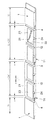
FIG. 1 is a perspective view showing the roofing structure of the first embodiment, FIG. 2 is a perspective view showing the roof tile of the first embodiment and the roof material with solar cells side by side, FIG. 3 shows the roof material with solar cells, (A) is a plan view, (B) is a side view, (C) is a sectional view showing a groove, FIGS. 4 (A) to (D) are perspective views showing various sectional shapes of the groove, and FIG. The perspective view which shows the roofing material with a solar cell of embodiment, FIG. 6 is sectional drawing which shows a ditch | groove.
[0018]
First Embodiment (FIGS. 1 to 4)
The roofing structure of the
[0019]
As shown in FIGS. 2 and 3, the
[0020]
At this time, the width a of the
[0021]
Moreover, it is preferable that the depth of the ditch | groove 12 is 4 mm or more. In this embodiment, it is 5 mm.
[0022]
Moreover, it is preferable that the cross-sectional shape of the ditch | groove 12 is a substantially rectangular shape like trapezoid (FIG. 4 (A) or rectangular figure 4 (B)). However, the cross-sectional shape of the
[0023]
The
[0024]
And the roof 2 with a solar cell, the groove | channel 2 produced between the
[0025]
The
[0026]
Further, the
[0027]
Therefore, according to the present embodiment, there are the following operations.
(1) Adopting a long roofing material in which the booth L of the
[0028]
(2) The groove a formed between the
[0029]
(3) By setting the depth of the
[0030]
(4) By making the cross-sectional shape of the
[0031]
(5) Since the
[0032]
{Circle around (6)} The
[0033]
(7) The above-mentioned (1) to (6) can be realized in the roof using the solar
[0034]
Second Embodiment (FIGS. 5 and 6)
The second embodiment is different from the first embodiment in that a
[0035]
The
[0036]
Even in the second embodiment, the same actions as the actions {circle around (1)} to {circle around (4)}, {circle around (7)} described above in the first embodiment are achieved.
[0037]
Although the embodiment of the present invention has been described in detail with reference to the drawings, the specific configuration of the present invention is not limited to this embodiment, and there are design changes and the like without departing from the gist of the present invention. Is included in the present invention.
[0038]
【The invention's effect】
As described above, according to the present invention, since the roof material with solar cells is provided on a part of the roof, it forms a beautiful line like a tiled roof that is uniformly continuous over the entire roof, and is excellent in design. The appearance of the roof can be obtained.
[Brief description of the drawings]
FIG. 1 is a perspective view showing a roofing structure of a first embodiment.
FIG. 2 is a perspective view showing the roof tile and the roofing material with solar cells side by side according to the first embodiment.
FIG. 3 shows a roof material with solar cells, (A) is a plan view, (B) is a side view, and (C) is a sectional view showing a concave groove.
4 (A) to 4 (D) are perspective views showing various cross-sectional shapes of concave grooves.
FIG. 5 is a perspective view showing a roof material with a solar cell according to a second embodiment.
FIG. 6 is a cross-sectional view showing a concave groove.
[Explanation of symbols]
DESCRIPTION OF
Claims (5)
太陽電池付き屋根材の小間を屋根瓦の小間の2倍以上の整数倍とし、該太陽電池付き屋根材の表面で、該屋根材の小間を該屋根瓦の小間と同等の間隔で割付けた位置に、流れ方向に沿う凹溝を設けたことを特徴とする屋根葺き構造。In the roofing structure in which roof tiles and roofing materials with solar cells are placed side by side,
Positions in which the booths with solar cells are an integer multiple of twice or more of the booth tiles, and the booths with the solar cells are assigned at the same intervals as the roof tile booths on the surface of the roofing material with solar cells. The roofing structure characterized by providing a concave groove along the flow direction.
太陽電池付き屋根材の下段に葺かれた、桁方向に隣り合う屋根瓦同士の間に生じる溝、太陽電池付き屋根材同士の間に生じる溝もしくは太陽電池付き屋根材と屋根瓦との間に生じる溝、又は太陽電池付き屋根材の前記凹溝の直上に、上段の太陽電池付き屋根材の上記排水溝を配置した請求項1〜3のいずれかに記載の屋根葺き構造.。The roof material with solar cells accommodates solar cells in a battery housing recess provided in the roof material body, and a drainage groove connected to the battery housing recess is provided at the water-side edge of the roof material body,
The groove formed between the roof tiles adjacent to each other in the girder direction, the groove formed between the roof materials with solar cells, or between the roof material with solar cells and the roof tiles, sown in the lower stage of the roof material with solar cells The roofing structure according to any one of claims 1 to 3, wherein the drainage groove of the roof material with a solar cell in the upper stage is disposed immediately above the groove to be generated or the concave groove of the roof material with a solar cell. .
Priority Applications (1)
| Application Number | Priority Date | Filing Date | Title |
|---|---|---|---|
| JP2001107349A JP3609744B2 (en) | 2001-04-05 | 2001-04-05 | Roofing structure and roofing material with solar cells |
Applications Claiming Priority (1)
| Application Number | Priority Date | Filing Date | Title |
|---|---|---|---|
| JP2001107349A JP3609744B2 (en) | 2001-04-05 | 2001-04-05 | Roofing structure and roofing material with solar cells |
Publications (2)
| Publication Number | Publication Date |
|---|---|
| JP2002303021A JP2002303021A (en) | 2002-10-18 |
| JP3609744B2 true JP3609744B2 (en) | 2005-01-12 |
Family
ID=18959683
Family Applications (1)
| Application Number | Title | Priority Date | Filing Date |
|---|---|---|---|
| JP2001107349A Expired - Fee Related JP3609744B2 (en) | 2001-04-05 | 2001-04-05 | Roofing structure and roofing material with solar cells |
Country Status (1)
| Country | Link |
|---|---|
| JP (1) | JP3609744B2 (en) |
Cited By (2)
| Publication number | Priority date | Publication date | Assignee | Title |
|---|---|---|---|---|
| US8511006B2 (en) | 2009-07-02 | 2013-08-20 | Owens Corning Intellectual Capital, Llc | Building-integrated solar-panel roof element systems |
| US8782972B2 (en) | 2011-07-14 | 2014-07-22 | Owens Corning Intellectual Capital, Llc | Solar roofing system |
Families Citing this family (2)
| Publication number | Priority date | Publication date | Assignee | Title |
|---|---|---|---|---|
| JP2007154509A (en) * | 2005-12-05 | 2007-06-21 | Ntt Facilities Inc | Power generation system for taxi waiting place |
| JP2009019365A (en) * | 2007-07-10 | 2009-01-29 | Panasonic Electric Works Co Ltd | Roof structure of photovoltaic power system |
-
2001
- 2001-04-05 JP JP2001107349A patent/JP3609744B2/en not_active Expired - Fee Related
Cited By (2)
| Publication number | Priority date | Publication date | Assignee | Title |
|---|---|---|---|---|
| US8511006B2 (en) | 2009-07-02 | 2013-08-20 | Owens Corning Intellectual Capital, Llc | Building-integrated solar-panel roof element systems |
| US8782972B2 (en) | 2011-07-14 | 2014-07-22 | Owens Corning Intellectual Capital, Llc | Solar roofing system |
Also Published As
| Publication number | Publication date |
|---|---|
| JP2002303021A (en) | 2002-10-18 |
Similar Documents
| Publication | Publication Date | Title |
|---|---|---|
| JP2001098703A (en) | Roof structure and roofing method | |
| JP3609744B2 (en) | Roofing structure and roofing material with solar cells | |
| WO2017098607A1 (en) | Solar cell module and roof structure | |
| JP3626417B2 (en) | Roofing with solar cells and roofing structure | |
| JP2001173161A (en) | Solar battery module tile and roof | |
| JPH1088741A (en) | Roof tile having solar battery | |
| JP2000154620A (en) | Roof tile | |
| JPH0610020Y2 (en) | Root | |
| JP3504640B2 (en) | Tiles incorporating solar cells | |
| JP2001049799A (en) | Solar battery module tile | |
| JP3121522B2 (en) | Roofing material and its roofing structure | |
| JPH0542170Y2 (en) | ||
| JP2005240274A (en) | Roof tile with built-in solar battery | |
| JPH09268709A (en) | Roof tile and roofing structure | |
| JPH086909Y2 (en) | Drainer mounting structure | |
| JP2549450Y2 (en) | Roof panel connection structure | |
| KR200205952Y1 (en) | A waterproof panel for epdm | |
| JP2002199818A (en) | Wall panel for greening | |
| JPH0967881A (en) | Drainage structure of glass block panel | |
| JPH0735976Y2 (en) | Drainer | |
| JPS63805Y2 (en) | ||
| JPH03293453A (en) | Material of flat roof and construction thereof | |
| JP2009019365A (en) | Roof structure of photovoltaic power system | |
| JPH11343723A (en) | Outdoor floor structure | |
| JP2000154615A (en) | Roof tile |
Legal Events
| Date | Code | Title | Description |
|---|---|---|---|
| A977 | Report on retrieval |
Free format text: JAPANESE INTERMEDIATE CODE: A971007 Effective date: 20040903 |
|
| TRDD | Decision of grant or rejection written | ||
| A01 | Written decision to grant a patent or to grant a registration (utility model) |
Free format text: JAPANESE INTERMEDIATE CODE: A01 Effective date: 20040922 |
|
| A61 | First payment of annual fees (during grant procedure) |
Free format text: JAPANESE INTERMEDIATE CODE: A61 Effective date: 20041014 |
|
| FPAY | Renewal fee payment (event date is renewal date of database) |
Free format text: PAYMENT UNTIL: 20081022 Year of fee payment: 4 |
|
| FPAY | Renewal fee payment (event date is renewal date of database) |
Free format text: PAYMENT UNTIL: 20081022 Year of fee payment: 4 |
|
| FPAY | Renewal fee payment (event date is renewal date of database) |
Free format text: PAYMENT UNTIL: 20091022 Year of fee payment: 5 |
|
| FPAY | Renewal fee payment (event date is renewal date of database) |
Free format text: PAYMENT UNTIL: 20091022 Year of fee payment: 5 |
|
| FPAY | Renewal fee payment (event date is renewal date of database) |
Free format text: PAYMENT UNTIL: 20101022 Year of fee payment: 6 |
|
| FPAY | Renewal fee payment (event date is renewal date of database) |
Free format text: PAYMENT UNTIL: 20111022 Year of fee payment: 7 |
|
| FPAY | Renewal fee payment (event date is renewal date of database) |
Free format text: PAYMENT UNTIL: 20121022 Year of fee payment: 8 |
|
| FPAY | Renewal fee payment (event date is renewal date of database) |
Free format text: PAYMENT UNTIL: 20121022 Year of fee payment: 8 |
|
| FPAY | Renewal fee payment (event date is renewal date of database) |
Free format text: PAYMENT UNTIL: 20131022 Year of fee payment: 9 |
|
| LAPS | Cancellation because of no payment of annual fees |