JP3608677B2 - Mechanical parking equipment - Google Patents
Mechanical parking equipment Download PDFInfo
- Publication number
- JP3608677B2 JP3608677B2 JP30127395A JP30127395A JP3608677B2 JP 3608677 B2 JP3608677 B2 JP 3608677B2 JP 30127395 A JP30127395 A JP 30127395A JP 30127395 A JP30127395 A JP 30127395A JP 3608677 B2 JP3608677 B2 JP 3608677B2
- Authority
- JP
- Japan
- Prior art keywords
- pallet
- lift
- shelf
- berth
- hoistway
- Prior art date
- Legal status (The legal status is an assumption and is not a legal conclusion. Google has not performed a legal analysis and makes no representation as to the accuracy of the status listed.)
- Expired - Lifetime
Links
Images


Landscapes
- Warehouses Or Storage Devices (AREA)
Description
【0001】
【発明の属する技術分野】
本発明は、機械式駐車装置に係わるもので、特にパレットを用いた機械式駐車装置に関するものである。
【0002】
【従来の技術】
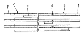
パレットを用いたスタッカクレーン方式の立体駐車装置は、すでに種々提案されている。たとえば、特公平5−38829号公報に開示されされた立体駐車場もスタッカクレーン方式の立体駐車装置の1つである。同公報に示されたスタッカクレーン方式の立体駐車場を図7および図8を用いて簡単に説明する。
【0003】
図7はその平面図、図8は入出庫部分を示す棚1段目mの要部側面図である。スタッカクレーン方式の立体駐車場は、図7に示すように、車両を運搬して昇降させるスタッカクレーンaと、この走行路bに沿って両側に設けられた棚群cとから構成されている。棚群cの1段目mにはパレット倉庫dが設けられ、棚群cの一端は車両の入庫口e、他端は出庫口fとなっている。
【0004】
車両は、図8に示すように、入庫口eでパレットgに載せられて入庫し、リフトkにより上昇させて棚の1段目mに設けられた入庫用コンベヤhでスタッカクレーンaの走行方向に順次移動する。適当な位置で入庫用コンベヤh上の車両の載った実車パレットg1はスタッカクレーンaによって空の棚に移動される。入庫用コンベヤaの端部にはパレット倉庫dが設けられている。また、パレット倉庫dから出庫口fまで出庫用コンベヤiが設けられている。出庫要求のあった棚に格納された実車パレットg1は、スタッカクレーンaにより出庫用コンベヤiに載せられて出庫口fまで搬送される。そして、出庫口fでリフタkにより降下し、車両は出庫可能になる。出庫用コンベヤiの下段には回収用コンベヤjが設けられ、出庫した車両の空パレットgをパレット倉庫dに搬送する。また、入庫用コンベヤhの下段にもパレット倉庫dから入庫口eまで回収用コンベヤjが設けられ、パレット倉庫dから空パレットgを入庫口eに供給するようになっている。
【0005】
【発明が解決しようとする課題】
しかしながら、上述したスタッカクレーン方式の立体駐車場においては、車両を格納すべき棚の1段目mに、車両を搬入する入庫用コンベヤhと車両を搬出する出庫用コンベヤiを設けるとともにその下段にも回収コンベヤjを設け、また、入庫用コンベヤhと出庫用コンベヤiとの間にパレット倉庫dを設けているので、棚の1段目mには車両を格納することができないし、また、コンベヤの設備費が嵩むという問題点があった。
【0006】
本発明は、上記のような問題点を解決しようとするものである。すなわち、本発明は、駐車装置の大部分を自動車の格納棚として使用するとともにパレットの入れ替えを円滑にして自動車の入出庫時間を短縮できるようにした機械式駐車装置を提供することを目的とするものである。
【0007】
【課題を解決するための手段】
上記目的を達成するため、請求項1の発明では、パレットが待機して自動車が直接乗り入れ退出可能な自動車入出庫用バースと、地下に多段、かつ、多列に設けられた自動車の格納棚と、前記自動車入出庫用バースの下方に設けられた昇降路を昇降してパレットの搬送を行う昇降リフトと、前記昇降路の両側に、かつ、格納棚の最上段の位置に設けられ、昇降リフトとの間でパレットの移載を行うバッファ棚と、該バッファ棚および前記格納棚との間でパレットの受け渡しを行う昇降可能なパレット移載装置を備えた走行移動台車とを有する。
【0008】
請求項2の発明では、パレットが待機して自動車が直接乗り入れ退出可能な自動車入出庫用バースと、地下に多段、かつ、多列に設けられた自動車の格納棚と、前記自動車入出庫用バースの側面に設けられた昇降路を昇降するとともに自動車入出庫用バースとの間でパレットの受け渡しをしてパレットの搬送を行う昇降リフトと、前記昇降路の両側に、かつ、格納棚の最上段の位置に設けられ、昇降リフトとの間でパレットの移載を行うバッファ棚と、該バッファ棚および前記格納棚との間でパレットの受け渡しを行う昇降可能なパレット移載装置を備えた走行移動台車とを有している。
【0009】
請求項3の発明では、前記バッファ棚は、パレット横行用ガイドと、昇降可能なパレット縦送り装置を有している
【0010】
本発明によれば、パレットの移送を、自動車入出庫用バース(以下「入出庫用バース」という。)とバッファ棚との間においては昇降リフトで、バッファ棚と各格納棚との間においては昇降可能なパレット移載装置を備えた走行移動台車により行い、昇降リフトが入出庫用バースでパレットの入出庫作業を行っている間、走行移動台車は格納棚とバッファ棚との間でパレットの受け渡し作業を行うので、パレットの入れ替えを円滑にして自動車の入出庫時間を短縮することができる。また、従来例に示した入庫用コンベヤ、出庫用コンベヤ、回収コンベヤおよびパレット倉庫が不要になるので設備費が大幅に安くなるとともに格納棚の1段目も自動車の格納に使用できるので駐車装置の容積当たりの自動車の格納台数が大幅に増える。
【0011】
【発明の実施の形態】
以下、本発明の好ましい実施形態を図面に基づいて説明する。
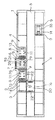
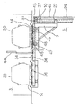
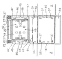
図1ないし図4は本発明の一実施形態を示すもので、図1は側面図、図2は図1の平面図、図3は図2の一部拡大図、図4は昇降リフトの側面図、図5は本発明の他の実施形態を示す昇降リフトの側面図、図6は図5の平面図である。
【0012】
1は地下に構築した駐車装置である。2はこの駐車装置1の地上側に設けられた自動車走行路であり、3は入出庫用バース(図1および図4)である。4は前記駐車装置1の地下側に設けた台車走行路5の両側に上下方向に所定の間隔をもって多段(本実施形態では3段)に、かつ、左右に多数配設され、自動車35を格納する格納棚である。6はこの格納棚4の最上段の位置の棚と前記入出庫用バース3との間に設けた昇降路であり、7はこの昇降路6を昇降する昇降リフトである。8は昇降路6下部両側の格納棚4の最上段の棚の位置に相当する位置に設けたバッファ棚で、その長さ方向の両端に設けたパレット横行用ガイド9(本実施形態ではローラ)と、パレット縦送り装置11(本実施形態ではローラ)とこのパレット縦送り装置11を駆動するパレット縦送り装置用駆動装置12とを有する昇降台13と、この昇降台13を昇降するリフタ(図示せず)とから構成されている。41は昇降リフタ7とバッファ棚8との間に配設したパレット縦送り補助装置である。
【0013】
前記昇降リフト7は、図3および図4に示すように、断面が逆L字状を形成(図4)しており、逆L字状の水平部には、パレット縦送り装置39(本実施形態ではローラ)と、このパレット縦送り装置39を駆動するパレット縦送り装置用駆動装置40とを有している。また、逆L字状の垂直部には、その上下方向に所定間隔をもって軸支した支持ローラ27を配設している。26は前記昇降路6に沿って地下側の床面25(図1では2階部分の高さに相当)に所定の間隔をもって立設した溝形の2本のレールで、その側面の凹所に、前記昇降リフト7に配設した支持ローラ27を嵌入し、昇降リフト7を片持ちで支持している。29は昇降リフト7とのバランスを取るために設けたカウンタウエイトで、ワイヤロープ42により吊り下げられ、昇降リフト7の昇降に合わせ昇降するようになっている。なお、28は補強部材、43はワイヤロープガイドシーブである。
【0014】
30は前記床面25の基台(図示せず)に軸支した駆動スプロケットであり、31はこの駆動スプロケット30と対向するように昇降路6上方の、前記2本のレール26間を連結した連結部材(図示せず)に軸支した従動スプロケットである。32はこれら駆動スプロケット30と従動スプロケット31にそれぞれ掛け渡し、その両端を前記昇降リフト7に設けた突出部材10に固着したチエーンである。33はこのチエーン32を回動させ、昇降リフト7を昇降させるチエーン駆動装置である。なお、34は前記入出庫用バース3内の自動車走行路の両側に設けた運転者用通路であり、35は自動車である。
【0015】
図3に示すように、15は前記台車走行路5に敷設された走行移動台車走行レールで、この走行移動台車走行レール15上を走行移動台車16が走行駆動装置(図示せず)の駆動により走行する。
【0016】
前記走行移動台車16は、走行方向の前後に格納棚4の最上段の高さよりも高く立設した主枠22と、この主枠22に設けた巻上装置21に巻き掛けられたチエーン(図示せず)により昇降可能に配設された昇降台20とから構成されている。また、この昇降台20には先端に突起23を有するアーム19の回動によりパレット14を移載するパレット移載装置18とパレット横行用ガイド24(本実施形態ではローラ)とが配設されている。そして、格納棚4またはバッファ棚8と走行移動台車16との間でパレット14の受け渡しをするときは、この昇降台20のパレット移載装置18を作動して行う。なお、17は走行移動台車16の走行車輪である。
【0017】
次に実施形態に基づく作用について説明する。
まず、駐車装置1の中に自動車35が1台も格納されていない状況では、パレット14は各格納棚4に保管されているほか、入出庫用バース3で入庫して来る自動車35のために待機している昇降リフト7に載置されている。たとえば、駐車装置1が60個の格納棚4を備えたものである場合には、格納棚4に60枚のパレット14を保管し、昇降リフト7にさらに1枚のパレット14を載置して合計61枚のパレット14を保管している。
【0018】
入庫しようとする自動車35が来ると入出庫用バース3に配設した入庫扉38(通常、昇降リフト7が上昇して入庫しようとする自動車35に備え待機しているときは開いている。)を開き、入出庫用バース3内にあらかじめ待機していたパレット14の上に自動車35を乗せ、運転者は自動車35から降りる。運転者が自動車35から離れたのを確認した後、前記入口扉38を閉め、昇降リフト7を降下し、バッファ棚8の所で停止する。そして、空パレット14が載置されていないバッファ棚8へ昇降リフト7の縦送り装置用駆動装置40により縦送り装置39を回動させて移載する。この際、バッファ棚8の昇降台13をリフタ(図示せず)によりパレット横行用ガイド9の位置より高く上昇させて、昇降リフト7の縦送り装置39と昇降台13の縦送り装置11との高さ位置を合わせておき、昇降リフト7の縦送り装置39からパレット14が移載されて来ると同時にバッファ棚8の昇降台13の縦送り装置用駆動装置12により縦送り装置11を回動させ、パレット14を昇降リフト7から受け取る。なお、38aは出庫扉である。
【0019】
昇降リフト7は、パレット14をバッファ棚8に移載すると、引き続き、反対側のバッファ棚8に載置されている空パレット14を、前記昇降リフト7からバッファ棚8に移載した場合と略反対の動作により受け取り、再び上昇して入出庫用バース3において次に入庫して来る自動車35のために待機する。
【0020】
一方、走行移動台車5は、入出庫用バース3において自動車35の入庫の手続きを開始すると同時に空パレット14が保管されている格納棚4の前まで走行して、昇降台20の位置を巻上装置21により格納棚4の高さに合わせ、パレット移載装置18を作動して格納棚4から空パレット14を受け取り、再びバッファ棚8の前まで走行して空パレット14をバッファ棚8に載置する。
【0021】
走行移動台車5は、バッファ棚8に空パレット14を載置すると、引き続き、反対側のバッファ棚8に移動し、すでに昇降リフト7から移載されている自動車35の載せた実パレット14をパレット移載装置18を作動してバッファ棚8から受け取り、さらに空パレット14を格納棚4から受け取った場合と略反対の動作により空パレット14の載置されていない格納棚4に移載して格納する。
【0022】
次に、出庫指令があって、駐車装置1の格納棚4から自動車35を出庫させるときは、走行移動台車16を走行させて出庫する自動車35が格納されている格納棚4の前で停止させ、パレット移載装置18により実車パレット14を受け取る。引き続き、バッファ棚8の前まで搬送し、パレット移載装置18により実車パレット14をバッファ棚8に受け渡す、バッファ棚8からは昇降リフト7に移載して入出庫用バース3まで上昇して自動車35を出庫させる。そして、そのまま次に入庫して来る自動車35のために入出庫用バース3で待機する。なお、出庫指令があった際、昇降リフト7上に空パレット14が載置されているときは、一旦、昇降リフト7を降下させて空パレット14をバッファ棚8に預けておく。
【0023】
図5および図6は本発明の他の実施形態を示すものである。前記実施形態では入出庫用バース3を昇降路6の上方に設けたが、本実施形態では昇降路6の上方を空間とし、入出庫用バース3を昇降路6の側面に設けたものである。すなわち、入出庫用バース3内に、この入出庫用バース3と昇降リフト7との間でパレット14の受け渡しを行うパレット横送り装置36(本実施形態ではローラ)と、このパレット横送り装置36を駆動するパレット横送り装置用駆動装置37を設けている。また、昇降リフト7には、その長さ方向の両側に設けたパレット横送り装置45(本実施形態ではローラ)と、このパレット横送り装置45を駆動するパレット横送り装置用駆動装置46と、パレット縦送り装置49(本実施形態ではローラ)とこのパレット縦送り装置49を駆動するパレット縦送り装置用駆動装置50とを有する昇降台48と、この昇降台48を昇降するリフタ47とが設けられている。なお、入出庫用バース3の両側には自動車乗り降り用床34が設けられており、また、その自動車乗り降り用床34には自動車運転者の歩行の障害にならない状態にパレット横送り装置36が設けられている。なお、44は安全扉である。
【0024】
次に、図5および図6に示す他の実施形態の作用について説明する。入庫しようとする自動車35が来ると入出庫用バース3に配設した入口扉38を開き、入出庫用バース3内にあらかじめ待機していたパレット14の上に自動車35を乗せ、運転者は自動車35から降りる。運転者が自動車35から離れたのを確認した後、入出庫用バース3と昇降路6との間に配設した安全扉44を開き(通常は閉めておく。)、入出庫用バース3に沿って設けられた昇降路6に、あらかじめ待機している昇降リフト7にパレット横送り装置36(入出庫用バース3に設けられている。)およびパレット横送り装置45(昇降リフト7に設けられている。)を回動させて受け渡し、引き続き、前記実施形態の動作と同じように、昇降リフト7を降下してバッファ棚8の所で停止し、空パレット14が載置されていないバッファ棚8へ昇降リフト7の縦送り装置用駆動装置12により縦送り装置11を回動させて移載する。なお、バッファ棚8から入出庫用バース3に移送するときは、略この反対の動作により行う。
【0025】
本発明は、上記実施形態に限定されるものではなく、バッファ棚8は、パレット横行用ガイドローラに代えてパレット横行用レールとし、パレット14に車輪を設けてもよいなど、特許請求の範囲に記載されている技術思想を逸脱しない範囲で種々の変更が可能である。
【0026】
【発明の効果】
以上述べたように、本発明によれば、大部分の格納棚を自動車の格納棚として使用できるので、駐車効率を高めることができる。また、昇降リフトが昇降して入出庫用バース3とバッファ棚8との間でパレット14の受け渡しを行っている間に、走行移動台車16がバッファ棚8と格納棚4との間で走行しながらパレット14を格納したり出庫作業をしているのでパレットの出し入れが円滑にでき、したがって、自動車の入出庫時間を短縮することもできるなどの効果を奏する。
【図面の簡単な説明】
【図1】本発明の一実施形態を示した側面図である。
【図2】図1の平面図である。
【図3】図2の一部拡大平面図である。
【図4】昇降リフトの側面図である。
【図5】本発明の他の実施形態を示す昇降リフトの側面図である。
【図6】図5の平面図である。
【図7】従来のスタッカクレーン方式の立体駐車装置の平面図である。
【図8】図7の入出庫部分を示す棚1段目の要部側面図である。
【符号の説明】
1 駐車装置
2 自動車走行路
3 自動車入出庫用バース
4 格納棚
5 台車走行路
6 昇降路
7 昇降リフト
8 バッファ棚
9 パレット横行用ガイド
10 突出部材
11 パレット縦送り装置
12 パレット縦送り装置用駆動装置
13 昇降台
14 パレット
15 走行移動台車走行用レール
16 走行移動台車
17 走行移動台車の走行車輪
18 パレット移載装置
19 アーム
20 昇降台
21 巻上装置
22 主枠
23 突起
24 パレット横行用ガイド
25 床面
26 レール
27 支持ローラ
28 補強部材
29 カウンタウエイト
30 駆動スプロケット
31 従動スプロケット
32 チエーン
33 チエーン駆動装置
34 運転者用通路
35 自動車
36 パレット横送り装置
37 パレット横送り装置用駆動装置
38 入庫扉
38a 出庫扉
39 パレット縦送り装置
40 パレット縦送り装置用駆動装置
41 パレット縦送り補助装置
42 ワイヤロープ
43 ワイヤロープガイドシーブ
44 安全扉
45 パレット横送り装置
46 パレット横送り装置用駆動装置
47 リフタ
48 昇降台
49 パレット縦送り装置
50 パレット縦送り装置用駆動装置
a スタッカクレーン
b 走行路
c 格納棚群
d パレット倉庫
e 入庫口
f 出庫口
g パレット
h 入庫用コンベヤ
i 出庫用コンベヤ
j 回収コンベヤ
k リフタ
m 棚の1段目[0001]
BACKGROUND OF THE INVENTION
The present invention relates to a mechanical parking apparatus, and more particularly to a mechanical parking apparatus using a pallet.
[0002]
[Prior art]
Various stacker crane type three-dimensional parking apparatuses using pallets have already been proposed. For example, a multilevel parking lot disclosed in Japanese Patent Publication No. 5-38829 is one of stacker crane type multilevel parking apparatuses. The stacker crane type three-dimensional parking lot disclosed in the publication will be briefly described with reference to FIGS.
[0003]
FIG. 7 is a plan view thereof, and FIG. 8 is a side view of the main part of the first shelf m showing the storage / exit portion. As shown in FIG. 7, the stacker crane type three-dimensional parking lot is composed of a stacker crane a that moves a vehicle up and down, and a shelf group c that is provided on both sides along the traveling path b. A pallet warehouse d is provided in the first stage m of the shelf group c, and one end of the shelf group c is a vehicle entrance e and the other end is an exit f.
[0004]
As shown in FIG. 8, the vehicle is placed on a pallet g at a warehousing port e, moved up by a lift k, and moved in a traveling direction of the stacker crane a by a warehousing conveyor h provided at the first stage m of the shelf. Move sequentially. The actual vehicle pallet g1 on which the vehicle on the warehousing conveyor h is placed at an appropriate position is moved to an empty shelf by the stacker crane a. A pallet warehouse d is provided at the end of the warehousing conveyor a. Further, a delivery conveyor i is provided from the pallet warehouse d to the delivery port f. The actual vehicle pallet g1 stored in the shelf requested to be delivered is placed on the delivery conveyor i by the stacker crane a and conveyed to the delivery port f. Then, the vehicle is lowered by the lifter k at the exit port f, and the vehicle can exit. A recovery conveyor j is provided at the lower stage of the delivery conveyor i, and the empty pallet g of the delivered vehicle is conveyed to the pallet warehouse d. Further, a recovery conveyor j is provided at the lower stage of the warehousing conveyor h from the pallet warehouse d to the warehousing port e, and an empty pallet g is supplied from the pallet warehouse d to the warehousing port e.
[0005]
[Problems to be solved by the invention]
However, in the above-described stacker crane type multi-story parking lot, the first stage m of the shelf in which the vehicle is to be stored is provided with a loading conveyor h for loading the vehicle and a loading conveyor i for unloading the vehicle. Is also provided with a recovery conveyor j, and a pallet warehouse d is provided between the entry conveyor h and the delivery conveyor i, so that the vehicle cannot be stored in the first stage m of the shelf, There was a problem that the equipment cost of the conveyor increased.
[0006]
The present invention is intended to solve the above problems. That is, an object of the present invention is to provide a mechanical parking device that uses most of the parking device as a storage shelf for a vehicle and that can smoothly change the pallet to shorten the time for loading and unloading the vehicle. Is.
[0007]
[Means for Solving the Problems]
In order to achieve the above object, in the invention of claim 1, a car berthing berth in which a pallet waits and a car can directly enter and leave, and a car storage shelf provided in multiple rows and multiple rows underground. A lifting lift that lifts and lowers the hoistway provided below the vehicle entrance and exit berth and conveys the pallet, and is provided on both sides of the hoistway and at the uppermost position of the storage shelf. A buffer shelf for transferring pallets to and from the vehicle, and a traveling carriage equipped with a pallet transfer device capable of moving up and down for transferring pallets between the buffer shelf and the storage shelf.
[0008]
According to the invention of
[0009]
According to a third aspect of the present invention, the buffer shelf has a pallet traverse guide and a pallet vertical feed device capable of moving up and down.
According to the present invention, the pallet is transferred between the buffer shelf and each storage shelf by a lifting lift between the vehicle loading / unloading berth (hereinafter referred to as “loading / unloading berth”) and the buffer shelf. The traveling cart is equipped with a pallet transfer device that can move up and down, and while the lifting lift performs the pallet loading / unloading work at the loading / unloading berth, the traveling traveling cart moves the pallet between the storage shelf and the buffer shelf. Since the delivery work is performed, it is possible to smoothly change the pallet and to shorten the time for entering and leaving the car. In addition, since the warehousing conveyor, the shipping conveyor, the recovery conveyor and the pallet warehouse shown in the conventional example are not necessary, the equipment cost is greatly reduced and the first stage of the storage shelf can be used for storing the car. The number of cars stored per volume increases significantly.
[0011]
DETAILED DESCRIPTION OF THE INVENTION
Hereinafter, preferred embodiments of the present invention will be described with reference to the drawings.
1 to 4 show an embodiment of the present invention. FIG. 1 is a side view, FIG. 2 is a plan view of FIG. 1, FIG. 3 is a partially enlarged view of FIG. FIG. 5 is a side view of a lifting lift showing another embodiment of the present invention, and FIG. 6 is a plan view of FIG.
[0012]
Reference numeral 1 denotes a parking device built underground.
[0013]
As shown in FIGS. 3 and 4, the
[0014]
[0015]
As shown in FIG. 3,
[0016]
The traveling
[0017]
Next, the operation based on the embodiment will be described.
First, in a situation where no
[0018]
When a
[0019]
When the
[0020]
On the other hand, the traveling
[0021]
When the
[0022]
Next, when there is a delivery command and the
[0023]
5 and 6 show another embodiment of the present invention. In the above embodiment, the entry /
[0024]
Next, the operation of the other embodiment shown in FIGS. 5 and 6 will be described. When the
[0025]
The present invention is not limited to the above embodiment, and the
[0026]
【The invention's effect】
As described above, according to the present invention, most storage shelves can be used as automobile storage shelves, so that parking efficiency can be improved. Further, while the lift lift is raised and lowered to transfer the
[Brief description of the drawings]
FIG. 1 is a side view showing an embodiment of the present invention.
2 is a plan view of FIG. 1. FIG.
FIG. 3 is a partially enlarged plan view of FIG. 2;
FIG. 4 is a side view of the lift.
FIG. 5 is a side view of an elevating lift showing another embodiment of the present invention.
6 is a plan view of FIG. 5. FIG.
FIG. 7 is a plan view of a conventional stacker crane type three-dimensional parking apparatus.
8 is a side view of the main part of the first stage of the shelf showing the loading / unloading part of FIG. 7. FIG.
[Explanation of symbols]
DESCRIPTION OF SYMBOLS 1
Claims (3)
Priority Applications (1)
| Application Number | Priority Date | Filing Date | Title |
|---|---|---|---|
| JP30127395A JP3608677B2 (en) | 1995-11-20 | 1995-11-20 | Mechanical parking equipment |
Applications Claiming Priority (1)
| Application Number | Priority Date | Filing Date | Title |
|---|---|---|---|
| JP30127395A JP3608677B2 (en) | 1995-11-20 | 1995-11-20 | Mechanical parking equipment |
Publications (2)
| Publication Number | Publication Date |
|---|---|
| JPH09144366A JPH09144366A (en) | 1997-06-03 |
| JP3608677B2 true JP3608677B2 (en) | 2005-01-12 |
Family
ID=17894842
Family Applications (1)
| Application Number | Title | Priority Date | Filing Date |
|---|---|---|---|
| JP30127395A Expired - Lifetime JP3608677B2 (en) | 1995-11-20 | 1995-11-20 | Mechanical parking equipment |
Country Status (1)
| Country | Link |
|---|---|
| JP (1) | JP3608677B2 (en) |
-
1995
- 1995-11-20 JP JP30127395A patent/JP3608677B2/en not_active Expired - Lifetime
Also Published As
| Publication number | Publication date |
|---|---|
| JPH09144366A (en) | 1997-06-03 |
Similar Documents
| Publication | Publication Date | Title |
|---|---|---|
| JP3357771B2 (en) | Underground multi-story parking device | |
| JPH0617640B2 (en) | Statka crane multi-level parking lot | |
| WO2019229820A1 (en) | Mechanical parking device with berth and operation method for same | |
| JP3608677B2 (en) | Mechanical parking equipment | |
| JPH09158513A (en) | Mechanical type parking equipment | |
| JPH07259371A (en) | Multi-story parking equipment | |
| JP3613418B2 (en) | Mechanical parking device | |
| JPH0355717Y2 (en) | ||
| JPH0617637B2 (en) | Multistory parking lot | |
| JP3712149B2 (en) | 3 column type elevating parking system | |
| JP3712147B2 (en) | 3 column type elevating parking system | |
| JP2863712B2 (en) | Pallet lifter in mechanical parking lot | |
| JP3657829B2 (en) | Plane reciprocating parking device and method for loading and unloading the same | |
| JP3295066B2 (en) | Multi-stage multilevel parking device | |
| JP4065633B2 (en) | Mechanical parking equipment | |
| JP4065631B2 (en) | Plane reciprocating parking system | |
| JPH04353174A (en) | Multi-tier parking device | |
| JP3820651B2 (en) | Automated warehouse for vehicle storage | |
| JPH09256662A (en) | Mechanical type parking device | |
| JP2002309792A (en) | Lift type parking device | |
| JPH04353173A (en) | Multi-tier parking device | |
| JPH02104867A (en) | Elevator type multi-story parking device | |
| JP3838603B2 (en) | Plane reciprocating multilevel parking system | |
| JPH1122230A (en) | Three vertical line type elevation parking system | |
| JPH06108694A (en) | Multistory parking equipment |
Legal Events
| Date | Code | Title | Description |
|---|---|---|---|
| A977 | Report on retrieval |
Free format text: JAPANESE INTERMEDIATE CODE: A971007 Effective date: 20040301 |
|
| A131 | Notification of reasons for refusal |
Free format text: JAPANESE INTERMEDIATE CODE: A131 Effective date: 20040518 |
|
| A521 | Written amendment |
Free format text: JAPANESE INTERMEDIATE CODE: A523 Effective date: 20040618 |
|
| TRDD | Decision of grant or rejection written | ||
| A01 | Written decision to grant a patent or to grant a registration (utility model) |
Free format text: JAPANESE INTERMEDIATE CODE: A01 Effective date: 20040924 |
|
| A61 | First payment of annual fees (during grant procedure) |
Free format text: JAPANESE INTERMEDIATE CODE: A61 Effective date: 20041007 |
|
| S111 | Request for change of ownership or part of ownership |
Free format text: JAPANESE INTERMEDIATE CODE: R313113 |
|
| R360 | Written notification for declining of transfer of rights |
Free format text: JAPANESE INTERMEDIATE CODE: R360 |
|
| R371 | Transfer withdrawn |
Free format text: JAPANESE INTERMEDIATE CODE: R371 |
|
| S111 | Request for change of ownership or part of ownership |
Free format text: JAPANESE INTERMEDIATE CODE: R313113 |
|
| R350 | Written notification of registration of transfer |
Free format text: JAPANESE INTERMEDIATE CODE: R350 |
|
| FPAY | Renewal fee payment (event date is renewal date of database) |
Free format text: PAYMENT UNTIL: 20071022 Year of fee payment: 3 |
|
| FPAY | Renewal fee payment (event date is renewal date of database) |
Free format text: PAYMENT UNTIL: 20081022 Year of fee payment: 4 |
|
| FPAY | Renewal fee payment (event date is renewal date of database) |
Free format text: PAYMENT UNTIL: 20091022 Year of fee payment: 5 |
|
| FPAY | Renewal fee payment (event date is renewal date of database) |
Free format text: PAYMENT UNTIL: 20101022 Year of fee payment: 6 |
|
| FPAY | Renewal fee payment (event date is renewal date of database) |
Free format text: PAYMENT UNTIL: 20101022 Year of fee payment: 6 |
|
| S533 | Written request for registration of change of name |
Free format text: JAPANESE INTERMEDIATE CODE: R313533 |
|
| FPAY | Renewal fee payment (event date is renewal date of database) |
Free format text: PAYMENT UNTIL: 20101022 Year of fee payment: 6 |
|
| R350 | Written notification of registration of transfer |
Free format text: JAPANESE INTERMEDIATE CODE: R350 |
|
| S531 | Written request for registration of change of domicile |
Free format text: JAPANESE INTERMEDIATE CODE: R313531 |
|
| FPAY | Renewal fee payment (event date is renewal date of database) |
Free format text: PAYMENT UNTIL: 20101022 Year of fee payment: 6 |
|
| R350 | Written notification of registration of transfer |
Free format text: JAPANESE INTERMEDIATE CODE: R350 |
|
| FPAY | Renewal fee payment (event date is renewal date of database) |
Free format text: PAYMENT UNTIL: 20111022 Year of fee payment: 7 |
|
| FPAY | Renewal fee payment (event date is renewal date of database) |
Free format text: PAYMENT UNTIL: 20121022 Year of fee payment: 8 |
|
| FPAY | Renewal fee payment (event date is renewal date of database) |
Free format text: PAYMENT UNTIL: 20131022 Year of fee payment: 9 |
|
| R250 | Receipt of annual fees |
Free format text: JAPANESE INTERMEDIATE CODE: R250 |
|
| R250 | Receipt of annual fees |
Free format text: JAPANESE INTERMEDIATE CODE: R250 |
|
| R250 | Receipt of annual fees |
Free format text: JAPANESE INTERMEDIATE CODE: R250 |
|
| EXPY | Cancellation because of completion of term |