JP3608552B2 - Vertical sliding sliding door device - Google Patents
Vertical sliding sliding door device Download PDFInfo
- Publication number
- JP3608552B2 JP3608552B2 JP2002013378A JP2002013378A JP3608552B2 JP 3608552 B2 JP3608552 B2 JP 3608552B2 JP 2002013378 A JP2002013378 A JP 2002013378A JP 2002013378 A JP2002013378 A JP 2002013378A JP 3608552 B2 JP3608552 B2 JP 3608552B2
- Authority
- JP
- Japan
- Prior art keywords
- door
- vertical
- support plate
- sliding
- weight
- Prior art date
- Legal status (The legal status is an assumption and is not a legal conclusion. Google has not performed a legal analysis and makes no representation as to the accuracy of the status listed.)
- Expired - Fee Related
Links
- 210000000078 claw Anatomy 0.000 claims description 16
- 230000000149 penetrating effect Effects 0.000 claims description 3
- 230000005484 gravity Effects 0.000 description 4
- 238000010276 construction Methods 0.000 description 3
- 238000010586 diagram Methods 0.000 description 3
- 238000009434 installation Methods 0.000 description 2
- 230000000694 effects Effects 0.000 description 1
- 239000011521 glass Substances 0.000 description 1
- JGPMMRGNQUBGND-UHFFFAOYSA-N idebenone Chemical compound COC1=C(OC)C(=O)C(CCCCCCCCCCO)=C(C)C1=O JGPMMRGNQUBGND-UHFFFAOYSA-N 0.000 description 1
- 229960004135 idebenone Drugs 0.000 description 1
- 238000012423 maintenance Methods 0.000 description 1
- 230000000452 restraining effect Effects 0.000 description 1
- 230000000630 rising effect Effects 0.000 description 1
- 239000007787 solid Substances 0.000 description 1
Images


Landscapes
- Wing Frames And Configurations (AREA)
Description
【0001】
【発明の属する技術分野】
この出願の発明は、上下スライド引戸装置に関するものである。さらに詳しくは、この出願の発明は、キャビネット本体の前面開口部に設けられる上下方向にスライドする引戸において、扉を容易に取り付け、また、扉を取り外す際の安全性を確保することのできる上下スライド引戸装置に関するものである。
【0002】
【従来の技術】
キャビネット本体の前面開口部を開閉する戸には開き戸、引戸などが知られているが、上下方向にスライドしてキャビネット本体の前面開口部を開閉する上下スライド引戸装置が提案されてもいる。
【0003】
この上下スライド引戸装置は、たとえば図5に示すことができ、扉(1)が、キャビネット本体(2)の前面開口部(3)において上下方向にスライドするのを可能としたものであり、扉(1)の上下方向のスライドにより前面開口部(3)の開閉を行うことができる。
【0004】
具体的には、上下スライド引戸装置では、扉(1)にワイヤー、ロープなどの張力部材(4)を介して棒状などの形状に形成された錘(5)が連結されている。錘(5)は、扉(1)と同一若しくは略同一な重さを有し、キャビネット本体(2)の高さ方向にのびる、たとえばキャビネット本体(2)の背板側などに設けられるガイドレール(6)に沿って扉(1)と同じく上下方向にスライド自在とされている。この錘(5)と扉(1)とを連結する張力部材(4)はガイドローラー(7)によりガイドされている。したがって、上下スライド引戸装置では、扉(1)を上下方向にスライドさせ、任意の位置に停止させておくことができる。
【0005】
【発明が解決しようとする課題】
しかしながら、以上の上下スライド引戸装置には幾つかの問題が指摘される。その一つに扉(1)の取付作業性及びメンテナンス時などにおいて扉(1)を取り外す際の安全性について問題がある。
【0006】
すなわち、たとえば、上下スライド引戸装置において、パーツごとに分解し、現場施工を可能にし、また、ガラスなどから形成される扉(1)が破損した時にこれを取換え容易とするために、扉(1)をその左右両側部に設けた縦框に、張力部材(4)の一端が連結された支持プレートを接続することにより、扉(1)をその支持プレートに支持させ、扉(1)の張力部材(4)を介しての錘(5)との連結を可能とする構造を採用する場合、扉(1)には、前述の通り、これと同一若しくは略同一な重さを有する錘(5)が連結されているため、扉(1)の取付時、錘(5)はその自重によりキャビネット本体(2)の最下端に、一方、支持プレートは最上端に位置する。したがって、扉(1)を支持プレートに取り付けるためには、支持プレートを、一旦、取付作業が容易となる高さまで引き下げる必要があるが、この時、錘(5)に作用する重力により支持プレートに作用する張力部材(4)の張力は常に鉛直上方であるため、支持プレートの上方スライドを制しつつ扉(1)の取付作業を行わなければならない。このため、扉(1)の取付作業は労力を要し、決して容易ではないのである。
【0007】
また、扉(1)の交換のために扉(1)を支持プレートから外すと、張力部材(4)における力のつりあいがくずれるため、錘(5)は、これに作用する重力により自由落下する。この錘(5)の自由落下にともない支持プレートが急激に上昇するため、非常に危険であるとともに、上下スライド引戸装置が損傷するおそれもある。
【0008】
この出願の発明は、このような事情に鑑みてなされたものであり、キャビネット本体の前面開口部に設けられる上下方向にスライドする引戸において、扉を容易に取り付け、また、扉を取り外す際の安全性を確保することのできる上下スライド引戸装置を提供することを解決すべき課題としている。
【0009】
【課題を解決するための手段】
この出願の発明は、以上の課題を解決するものとして、前後に並置された複数枚の扉のそれぞれに張力部材を介して扉と同一若しくは略同一な重さの錘が連結され、各扉の上下方向のスライドが可能とされた上下スライド引戸装置であり、各扉は、対向する一対の縦框、横框をそれぞれ備え、左右両縦框において支持プレートに支持され、支持プレートは、少なくともその上下両端部において縦框を固定可能であり、各扉の左右両縦框若しくは支持プレートのいずれか一方は、長さ方向の中央部に、突出する引っ掛け爪を有し、支持プレート若しくは各扉の左右両縦框の他方における長さ方向の中央部に、前記引っ掛け爪が挿入及び係合可能な、表裏方向に貫通する係合孔が形成され、扉が支持プレートに未固定若しくは固定解除された時、引っ掛け爪が係合孔の上端に係合し、扉の左右両縦框が支持プレートにより係止され、仮固定されることを特徴とする上下スライド引戸装置(請求項1)を提供する。
【0010】
またこの出願の発明は、錘を固定し、その上下スライドを不能にする固定具を備えること(請求項2)を一態様として提供する。
【0011】
以下、図面に沿ってこの出願の発明の上下スライド引戸装置についてさらに詳しく説明する。
【0012】
なお、以下の実施形態において扉の枚数は2枚が例示されているが、この出願の発明の上下スライド引戸装置は特に2枚扉に限定されることはなく、2枚以上の複数枚の扉を対象としている。
【0013】
【発明の実施の形態】
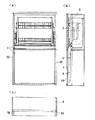
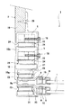
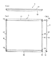
図1<a><b><c>は、それぞれ、この出願の発明の上下スライド引戸装置の一実施形態をキャビネット本体とともに示した透視正面図、側断面図、平面図である。図2は、この出願の発明の上下スライド引戸装置における左側の縦枠部分を具体的に示した横断面図である。また、図3<a><b><c>は、それぞれ、図1に示した扉の一形態を示した正面図、側面図、平面図であり、図4<a><b><c>は、それぞれ、図2に示した支持プレートの一形態を示した正面図、側面図、平面図である。
【0014】
この出願の発明の上下スライド引戸装置では、図1<a><b><c>に示したように、前後に並置された複数枚の扉(1)のそれぞれに、図5に示したようなワイヤー、ロープなどの張力部材(4)を介して扉(1)と同一若しくは略同一な重さの錘(5)が連結され、各扉(1)の上下方向のスライドが可能とされている。各扉(1)は、図2に示したように、その左右両端部に配設された縦框(8)において支持プレート(9)を接続し、これに支持されている。この支持プレート(9)の表裏いずれかの面に、張力部材(4)の一端が接続されている。張力部材(4)の他端は、扉(1)の左右両側に一つずつ独立して配設された錘(5)に接続され、支持プレート(9)と錘(5)とが連結されている。そして、支持プレート(9)の張力部材(4)が接続された側の部位(9a)、錘(5)は、それぞれ、中空柱状の縦枠(10)の中空部(10a)(10b)に収納可能である。これらの中空部(10a)(10b)は、縦枠(10)において連設一体化することができる。もちろん、錘(5)については、縦枠(10)の中空部(10b)に収納せず、図5に示したように、キャビネット本体(2)の背板側などにガイドレール(6)を設けるなどして上下スライド自在とすることもできる。
【0015】
また、この出願の発明の上下スライド引戸装置では、図3<a><b><c>に示したように、各扉(1)は、対向する一対の縦框(8)、横框(11)をそれぞれ備え、左右両縦框(8)において、図2に示したように、支持プレート(9)に支持される。下側の横框(11)にはその前面に、図3<a><b><c>に示したように、操作用の取っ手(12)を設けることができる。一方、支持プレート(9)は、少なくともその上下両端部において扉(1)の縦框(8)を固定可能としている。具体的には、図3<a><b><c>及び図4<a><b><c>に示したように、扉(1)の縦框(8)、支持プレート(9)のそれぞれの上下両端部において重なり合う部位にネジ孔(13)(14)を形成し、図2に示したようにネジ(15)により固定することが例示される。
【0016】
さらに、この出願の発明の上下スライド装置では、各扉(1)の左右両縦框(8)若しくは支持プレート(9)のいずれか一方が、長さ方向の中央部に、突出する引っ掛け爪(16)を有している。図3<a><b><c>及び図4<a><b><c>に示した実施形態では、支持プレート(9)が引っ掛け爪(16)を有している。図4<a>図中の実線円(A)内を図4図中に拡大して示したように(拡大図において左側の図は、右側の図の矢印方向の断面図である)、引っ掛け爪(16)が支持プレート(9)に設けられる場合、その引っ掛け爪(16)は、支持プレート(9)の表面から前方に突出するように設けることができる。具体的には、拡大図に示したように、支持プレート(9)の長さ方向の中央部をやや縦長に切り欠き、下端を切り離さずに表面前方に折り曲げ、また、ある程度突出した部分において上方へ折り返し、断面L字形の形状などに形成することができる。引っ掛け爪(16)は、上記の通り、図3<a><b><c>に示した各扉(1)の左右両縦框(8)にも設けることができるが、この場合、引っ掛け爪(16)の突出方向は、支持プレート(9)に設ける場合とは逆で、縦框(8)の裏面後方に突出するように配設する。
【0017】
そして、この出願の発明の上下スライド引戸装置では、支持プレート(9)若しくは各扉(1)の左右両縦框(8)の他方における長さ方向の中央部に、引っ掛け爪(16)が挿入及び係合可能な、たとえば図3<a><b>に示したような表裏方向に貫通する係合孔(17)が形成される。この係合孔(17)の形状及び大きさについては特に制限はなく、引っ掛け爪(16)の形状及び大きさに応じて適宜決めることができる。たとえば形状については、図3<a><b>に示したような縦長楕円形の他、だるま形などとすることができる。
【0018】
以上の構成を備えたこの出願の発明の上下スライド引戸装置では、扉(1)を支持プレート(9)に取り付ける際、係合孔(17)に引っ掛け爪(16)を挿入し、扉(1)の自重により引っ掛け爪(16)を係合孔(17)の上端に係合させることができ、扉(1)の左右両縦框(8)が支持プレート(9)に係止され、仮固定される。したがって、扉(1)が支持プレート(9)に未固定であっても、この仮固定状態において扉(1)及び錘(5)に作用する重力はつりあうため、支持プレート(9)が急激に上昇することはなく、安定した状態において図2に示したネジ(15)を用いた固定を行うことができる。扉(1)の取付作業が容易となる。
【0019】
また、扉(1)の取換え時には、固定用のネジ(15)を外すと、錘(5)に作用する重力により支持プレート(9)が上昇するが、その上昇は係合孔(17)の長さ以内のごくわずかな距離であり、引っ掛け爪(16)はほどなく係合孔(17)の上端に係合し、扉(1)は、左右両縦框(8)において支持プレート(9)に支持される。したがって、支持プレート(9)が急激に上昇することはなく、安全性が確保され、図1<a><b><c>及び図2に示した縦枠(10)などの部位が損傷することもない。
【0020】
このように、この出願の発明の上下スライド引戸装置は、この出願前に提案された上下スライド引戸装置の前述した通りの課題を解決することができる。
【0021】
なお、扉(1)の取付け及び取外し作業をより容易とするために、この出願の発明の上下スライド引戸装置には、図2に示したように、錘(5)の上下スライドを阻止し、所望の位置に固定する、手回しネジなどとすることのできる固定具(18)を備えることができる。この固定具(18)により、錘(5)を縦枠(10)や図6に示したガイドレール(6)などに所望の位置に固定すれば、扉(1)を取り付け、また、取り外す際に、支持プレート(9)の不意の上昇をより確実に防止することができ、また、取付け時及び取外し後の急な上昇を抑えるために、支持プレート(9)に人手などを添える必要がなく、作業性に優れる。このような固定具(18)を用いての錘(5)の固定は、上下スライド引戸装置の搬送時、施工時などにおいて錘(5)が不意に落下し、搬送中の部品が破損したり、扉(1)の施工に支障をきたしたりするなどを防止するのにも有効となる。
【0022】
また、図2に示したように、この出願の発明の上下スライド引戸装置では、縦枠(10)は、キャビネット本体(2)の側板(19)の前端にネジ(20)などにより取り付けることができる。縦枠(10)の中空部(10a)(10b)は、前述の通り、連設一体化することができ、この場合、支持プレート(9)の表裏いずれかの面にはローラー(21)を、錘(5)の表裏いずれかの面にもローラー(22)を配設し、これらローラー(21)(22)をそれぞれガイドする複数本のレール(23)(24)を、縦枠(10)の内面に中空部(10a)(10b)に突出させて一体に設けることができる。以上の構成により、扉(1)及び錘(5)のいずれも、縦枠(10)の内面に設けられたレール(23)(24)に沿ってローラー(21)(22)がガイドされて縦枠(10)の上下方向にスムーズにスライド自在となる。
【0023】
もちろん、この出願の発明は、以上の実施形態によって限定されるものではない。扉の縦框及び横框の構成及び構造をはじめ、支持プレート及び縦枠の構成及び構造などの細部については様々な態様が可能であることはいうまでもない。
【0024】
【発明の効果】
以上詳しく説明した通り、この出願の発明によって、キャビネット本体の前面開口部に設けられる上下方向にスライドする引戸において、扉を容易に取り付け、また、扉を取り外す際の安全性を確保することができる。
【図面の簡単な説明】
【図1】<a><b><c>は、それぞれ、この出願の発明の上下スライド引戸装置の一実施形態をキャビネット本体とともに示した透視正面図、側断面図、平面図である。
【図2】この出願の発明の上下スライド引戸装置における左側の縦枠部分を具体的に示した横断面図である。
【図3】<a><b><c>は、それぞれ、図1に示した扉の一形態を示した正面図、側面図、平面図である。
【図4】<a><b><c>は、それぞれ、図2に示した支持プレートの一形態を示した正面図、側面図、平面図である。
【図5】この出願以前に提案されている上下スライド引戸装置の概要を示した斜視図及び要部拡大斜視図である。
【符号の説明】
1 扉
2 キャビネット本体
3 前面開口部
4 張力部材
5 錘
6 ガイドレール
7 ガイドローラー
8 縦框
9 支持プレート
9a 張力部材が接続された部位
10 縦枠
10a、10b 中空部
11 横框
12 取っ手
13、14 ネジ孔
15 ネジ
16 引っ掛け爪
17 係合孔
18 固定具
19 側板
20 ネジ
21、22 ローラー
23、24 レール[0001]
BACKGROUND OF THE INVENTION
The invention of this application relates to a vertical sliding sliding door device. More specifically, the invention of this application relates to a sliding door that slides in the vertical direction provided in the front opening of the cabinet body, and can be easily attached to the door, and can also ensure safety when removing the door. The present invention relates to a sliding door device.
[0002]
[Prior art]
As the door that opens and closes the front opening of the cabinet body, an open door, a sliding door, and the like are known. However, a vertical sliding door device that slides in the vertical direction to open and close the front opening of the cabinet body has been proposed.
[0003]
This vertical sliding sliding door device can be shown, for example, in FIG. 5, which allows the door (1) to slide up and down in the front opening (3) of the cabinet body (2). The front opening (3) can be opened and closed by the vertical sliding of (1).
[0004]
Specifically, in the vertical sliding sliding door device, a weight (5) formed in a bar shape or the like is connected to a door (1) via a tension member (4) such as a wire or a rope. The weight (5) has the same or substantially the same weight as the door (1) and extends in the height direction of the cabinet body (2). For example, the guide rail is provided on the back plate side of the cabinet body (2). Along with (6), the door (1) is slidable in the vertical direction. The tension member (4) connecting the weight (5) and the door (1) is guided by a guide roller (7). Therefore, in the vertical sliding sliding door device, the door (1) can be slid in the vertical direction and stopped at an arbitrary position.
[0005]
[Problems to be solved by the invention]
However, several problems are pointed out in the above-described vertical sliding sliding door device. For example, there are problems regarding the workability of attaching the door (1) and safety when removing the door (1) during maintenance.
[0006]
That is, for example, in a vertical sliding sliding door device, each part is disassembled to enable construction on site, and when the door (1) formed of glass or the like is broken, the door ( 1) is connected to the vertical gutters provided on the left and right sides thereof, and a support plate to which one end of the tension member (4) is connected is connected to the door (1) to support the door (1). When adopting a structure that enables connection with the weight (5) via the tension member (4), the door (1) has a weight (as described above) having the same or substantially the same weight as the above. Since 5) is connected, when the door (1) is attached, the weight (5) is positioned at the lowermost end of the cabinet body (2) by its own weight, while the support plate is positioned at the uppermost end. Therefore, in order to attach the door (1) to the support plate, it is necessary to lower the support plate once to a height at which the mounting operation can be easily performed. At this time, the gravity acts on the weight (5) to the support plate. Since the tension of the acting tension member (4) is always vertically upward, the door (1) must be attached while restraining the upward sliding of the support plate. For this reason, the installation work of the door (1) requires labor and is not easy.
[0007]
Further, when the door (1) is removed from the support plate for replacement of the door (1), the balance of the force in the tension member (4) is lost, so that the weight (5) falls freely due to the gravity acting on it. . As the weight (5) freely falls, the support plate rapidly rises, which is very dangerous and may cause damage to the vertical sliding sliding door device.
[0008]
The invention of this application has been made in view of such circumstances, and in the sliding door that slides in the vertical direction provided in the front opening of the cabinet body, the door can be easily attached and the safety when the door is removed. It is set as the problem which should be solved to provide the up-and-down sliding sliding door apparatus which can ensure property.
[0009]
[Means for Solving the Problems]
In the invention of this application, as a solution to the above-described problem, a weight having the same or substantially the same weight as the door is connected to each of a plurality of doors juxtaposed in front and rear via a tension member. A vertical sliding sliding door device capable of sliding in the vertical direction.Each door has a pair of opposed vertical and horizontal hoists, and is supported by the support plates on both the left and right vertical hoists. Vertical hooks can be fixed at both upper and lower ends, and either one of the left and right vertical hooks or the support plate of each door has a protruding hooking claw at the center in the length direction. An engagement hole penetrating in the front and back direction, into which the hooking claw can be inserted and engaged, is formed in the center portion in the length direction on the other side of the left and right vertical shafts, and the door is not fixed or released from the support plate. Time, Engages the upper end of the hanging claw engagement hole Tsu, left and right stile door is locked by the support plate, to provide a vertical slide sliding door device, characterized in that it is temporarily fixed (claim 1).
[0010]
The invention of this application also provides, as one aspect, a fixture that fixes the weight and disables the vertical sliding thereof (Claim 2).
[0011]
Hereinafter, the vertical sliding sliding door device of the present invention will be described in more detail with reference to the drawings.
[0012]
In the following embodiment, the number of doors is two, but the vertical sliding door device of the invention of this application is not particularly limited to two doors, and there are two or more doors. Is targeted.
[0013]
DETAILED DESCRIPTION OF THE INVENTION
1 <a><b><c> are respectively a perspective front view, a side sectional view, and a plan view showing an embodiment of the vertical sliding sliding door device of the present invention together with a cabinet body. FIG. 2 is a cross-sectional view specifically showing the left vertical frame portion in the vertical sliding sliding door device of the invention of this application. 3 <a><b><c> are respectively a front view, a side view, and a plan view showing an embodiment of the door shown in FIG. 1, and FIGS. 4 <a><b><c> Is the front view, side view, and top view which respectively showed one form of the support plate shown in FIG.
[0014]
In the vertical sliding sliding door device of the invention of this application, as shown in FIGS. 1 <a>, <b>, and <c>, as shown in FIG. A weight (5) having the same or substantially the same weight as that of the door (1) is connected via a tension member (4) such as a wire and a rope so that each door (1) can be slid in the vertical direction. Yes. As shown in FIG. 2, each door (1) is supported by a support plate (9) connected to a vertical rod (8) disposed at both left and right ends thereof. One end of the tension member (4) is connected to either the front or back surface of the support plate (9). The other end of the tension member (4) is connected to a weight (5) that is independently provided on each of the left and right sides of the door (1), and the support plate (9) and the weight (5) are connected. ing. And the site | part (9a) by which the tension | tensile_strength member (4) of the support plate (9) was connected, and the weight (5) are respectively in the hollow part (10a) (10b) of a hollow columnar vertical frame (10). It can be stored. These hollow portions (10a) and (10b) can be connected and integrated in the vertical frame (10). Of course, the weight (5) is not housed in the hollow portion (10b) of the vertical frame (10), and the guide rail (6) is placed on the back plate side of the cabinet body (2) as shown in FIG. It can also be slid up and down by providing it.
[0015]
Moreover, in the vertical sliding sliding door device of the invention of this application, as shown in FIGS. 3 <a><b><c>, each door (1) is composed of a pair of opposed vertical gutters (8), horizontal gutters ( 11) and is supported by the support plate (9) as shown in FIG. As shown in FIGS. 3 <a>, <b>, and <c>, an operation handle (12) can be provided on the front surface of the lower recumbent rod (11). On the other hand, the support plate (9) can fix the vertical rod (8) of the door (1) at least at both upper and lower ends thereof. Specifically, as shown in FIGS. 3 <a><b><c> and FIGS. 4 <a><b><c>, the vertical rod (8) of the door (1), the support plate (9) It is exemplified that screw holes (13) and (14) are formed in overlapping portions at the upper and lower end portions of each of these and fixed with screws (15) as shown in FIG.
[0016]
Furthermore, in the vertical slide device of the invention of this application, either one of the left and right vertical rods (8) or the support plate (9) of each door (1) has a hooking claw that protrudes at the center in the length direction ( 16). In the embodiment shown in FIGS. 3 <a><b><c> and FIGS. 4 <a><b><c>, the support plate (9) has a hooking claw (16). As shown in FIG. 4 by enlarging the inside of the solid circle (A) in FIG. 4 <a> (the left diagram in the enlarged diagram is a sectional view in the direction of the arrow in the right diagram). When the claw (16) is provided on the support plate (9), the hook claw (16) can be provided so as to protrude forward from the surface of the support plate (9). Specifically, as shown in the enlarged view, the central portion of the support plate (9) in the longitudinal direction is cut slightly vertically long, bent to the front of the surface without cutting off the lower end, and upward at a portion protruding to some extent. It can be folded back and formed into a L-shaped cross section. As described above, the hooking claws (16) can also be provided on the left and right vertical hooks (8) of each door (1) shown in FIGS. 3 <a><b><c>. The protrusion direction of the claw (16) is opposite to that of the support plate (9), and is arranged so as to protrude rearward of the vertical hook (8).
[0017]
In the vertical sliding sliding door device of the invention of this application, the hooking claw (16) is inserted into the center portion in the length direction of the other of the left and right vertical rods (8) of the support plate (9) or each door (1). Further, an engagement hole (17) penetrating in the front and back direction as shown in FIGS. 3 <a><b>, for example, is formed. There is no restriction | limiting in particular about the shape and magnitude | size of this engagement hole (17), According to the shape and magnitude | size of a hook nail | claw (16), it can determine suitably. For example, the shape may be a daruma shape in addition to a vertically long ellipse as shown in FIGS. 3 <a><b>.
[0018]
In the vertical sliding door device of the present invention having the above-described configuration, when the door (1) is attached to the support plate (9), the hooking claw (16) is inserted into the engagement hole (17), and the door (1 ) Can be engaged with the upper end of the engagement hole (17), and the left and right vertical hooks (8) of the door (1) are locked to the support plate (9). Fixed. Therefore, even if the door (1) is not fixed to the support plate (9), the gravity acting on the door (1) and the weight (5) is balanced in this temporarily fixed state, so that the support plate (9) It does not rise and can be fixed using the screw (15) shown in FIG. 2 in a stable state. The attachment work of the door (1) becomes easy.
[0019]
When the door (1) is replaced, if the fixing screw (15) is removed, the support plate (9) rises due to the gravity acting on the weight (5), but this rise is caused by the engagement hole (17). The hook nail (16) will soon engage the upper end of the engagement hole (17), and the door (1) will be supported by the support plate (8) 9) supported. Therefore, the support plate (9) does not rise suddenly, safety is ensured, and parts such as the vertical frame (10) shown in FIGS. 1 <a><b><c> and FIG. 2 are damaged. There is nothing.
[0020]
Thus, the vertical sliding sliding door device according to the invention of this application can solve the above-described problems of the vertical sliding sliding door device proposed before this application.
[0021]
In order to make it easier to attach and remove the door (1), the vertical sliding sliding door device of the invention of this application prevents the weight (5) from sliding up and down as shown in FIG. A fixture (18) can be provided that can be a hand screw, etc., that secures in a desired position. When the weight (5) is fixed to a desired position on the vertical frame (10), the guide rail (6) shown in FIG. 6 or the like by the fixing tool (18), the door (1) is attached or removed. In addition, it is possible to more reliably prevent the support plate (9) from rising unexpectedly, and it is not necessary to attach manual support to the support plate (9) in order to suppress a sudden increase during installation and after removal. Excellent workability. The fixing of the weight (5) using such a fixing tool (18) may cause the weight (5) to drop unexpectedly during transportation or construction of the vertical sliding sliding door device and damage the parts being transported. It is also effective to prevent the construction of the door (1) from being hindered.
[0022]
As shown in FIG. 2, in the vertical sliding sliding door device of the invention of this application, the vertical frame (10) is attached to the front end of the side plate (19) of the cabinet body (2) with a screw (20) or the like. it can. The hollow portions (10a) and (10b) of the vertical frame (10) can be connected and integrated as described above. In this case, the roller (21) is provided on either the front or back surface of the support plate (9). The rollers (22) are arranged on either the front or back surface of the weight (5), and a plurality of rails (23) (24) for respectively guiding the rollers (21) (22) are arranged in a vertical frame (10 ) On the inner surface of the hollow portion (10a) and (10b). With the above configuration, the rollers (21) and (22) are guided along the rails (23) and (24) provided on the inner surface of the vertical frame (10) in both the door (1) and the weight (5). It becomes possible to slide smoothly in the vertical direction of the vertical frame (10).
[0023]
Of course, the invention of this application is not limited by the above embodiments. It goes without saying that various aspects are possible for details such as the structure and structure of the vertical and horizontal lines of the door, as well as the structure and structure of the support plate and vertical frame.
[0024]
【The invention's effect】
As described in detail above, according to the invention of this application, in the sliding door that slides in the vertical direction provided in the front opening of the cabinet body, the door can be easily attached and safety when removing the door can be ensured. .
[Brief description of the drawings]
FIG. 1 is a perspective front view, a side cross-sectional view, and a plan view showing an embodiment of a vertical sliding sliding door device according to the invention of this application together with a cabinet body, respectively.
FIG. 2 is a cross-sectional view specifically showing a left vertical frame portion in the vertical sliding sliding door device of the invention of this application.
<a><b><c> are a front view, a side view, and a plan view, respectively, showing an embodiment of the door shown in FIG.
<a><b><c> are a front view, a side view, and a plan view, respectively, showing an embodiment of the support plate shown in FIG.
FIGS. 5A and 5B are a perspective view and an enlarged perspective view of an essential part showing an outline of a vertical sliding sliding door device proposed before this application.
[Explanation of symbols]
DESCRIPTION OF
Claims (2)
Priority Applications (1)
| Application Number | Priority Date | Filing Date | Title |
|---|---|---|---|
| JP2002013378A JP3608552B2 (en) | 2002-01-22 | 2002-01-22 | Vertical sliding sliding door device |
Applications Claiming Priority (1)
| Application Number | Priority Date | Filing Date | Title |
|---|---|---|---|
| JP2002013378A JP3608552B2 (en) | 2002-01-22 | 2002-01-22 | Vertical sliding sliding door device |
Publications (2)
| Publication Number | Publication Date |
|---|---|
| JP2003214018A JP2003214018A (en) | 2003-07-30 |
| JP3608552B2 true JP3608552B2 (en) | 2005-01-12 |
Family
ID=27650352
Family Applications (1)
| Application Number | Title | Priority Date | Filing Date |
|---|---|---|---|
| JP2002013378A Expired - Fee Related JP3608552B2 (en) | 2002-01-22 | 2002-01-22 | Vertical sliding sliding door device |
Country Status (1)
| Country | Link |
|---|---|
| JP (1) | JP3608552B2 (en) |
-
2002
- 2002-01-22 JP JP2002013378A patent/JP3608552B2/en not_active Expired - Fee Related
Also Published As
| Publication number | Publication date |
|---|---|
| JP2003214018A (en) | 2003-07-30 |
Similar Documents
| Publication | Publication Date | Title |
|---|---|---|
| KR101472962B1 (en) | A height adjustable safety railing | |
| JPS60116374A (en) | Weight lifting apparatus | |
| JP5429569B2 (en) | Safety block mounting jig for movable ladder | |
| JP5275881B2 (en) | Auxiliary handrail mounting bracket | |
| JP3608552B2 (en) | Vertical sliding sliding door device | |
| JP3180696U (en) | Handrail mounting bracket | |
| JP2014114642A (en) | Ladder attachable to and removable from footboard of construction site or job site, or simple construction site or simple job site | |
| KR20110087578A (en) | Folding rescue ladder with protective back cover on the veranda | |
| KR100844483B1 (en) | Installation equipment for descending life apparatus for emergency | |
| KR200486641Y1 (en) | Safety foothold for ladder | |
| IE20090433A1 (en) | Improvements in and relating to post drivers | |
| JP2020040808A (en) | Hand part for holding baggage | |
| JP3649190B2 (en) | Vertical sliding sliding door device | |
| US1823771A (en) | Window stage | |
| JP3214371U (en) | Tripod stand fixing | |
| JP2007031133A (en) | Hanging tool | |
| KR200398912Y1 (en) | Safety Net Assembly for Elevator way | |
| JP2000320132A (en) | Lift for scaffold | |
| KR200485098Y1 (en) | Door safety bar | |
| CN221289507U (en) | A protective net for a casting equipment conveying device | |
| JP2016141989A (en) | Construction sheet and net installation equipment | |
| JP5334018B2 (en) | Elevator hall door header case | |
| JP3544796B2 (en) | Lifting jig for elevator doorway device | |
| KR100814043B1 (en) | Left and right steel mounting bracket | |
| JP2024127154A (en) | Elevator Equipment |
Legal Events
| Date | Code | Title | Description |
|---|---|---|---|
| A977 | Report on retrieval |
Free format text: JAPANESE INTERMEDIATE CODE: A971007 Effective date: 20040913 |
|
| TRDD | Decision of grant or rejection written | ||
| A01 | Written decision to grant a patent or to grant a registration (utility model) |
Free format text: JAPANESE INTERMEDIATE CODE: A01 Effective date: 20040921 |
|
| A61 | First payment of annual fees (during grant procedure) |
Free format text: JAPANESE INTERMEDIATE CODE: A61 Effective date: 20041004 |
|
| R150 | Certificate of patent or registration of utility model |
Free format text: JAPANESE INTERMEDIATE CODE: R150 |
|
| FPAY | Renewal fee payment (event date is renewal date of database) |
Free format text: PAYMENT UNTIL: 20071022 Year of fee payment: 3 |
|
| FPAY | Renewal fee payment (event date is renewal date of database) |
Free format text: PAYMENT UNTIL: 20081022 Year of fee payment: 4 |
|
| FPAY | Renewal fee payment (event date is renewal date of database) |
Free format text: PAYMENT UNTIL: 20081022 Year of fee payment: 4 |
|
| FPAY | Renewal fee payment (event date is renewal date of database) |
Free format text: PAYMENT UNTIL: 20091022 Year of fee payment: 5 |
|
| FPAY | Renewal fee payment (event date is renewal date of database) |
Free format text: PAYMENT UNTIL: 20091022 Year of fee payment: 5 |
|
| S533 | Written request for registration of change of name |
Free format text: JAPANESE INTERMEDIATE CODE: R313533 |
|
| FPAY | Renewal fee payment (event date is renewal date of database) |
Free format text: PAYMENT UNTIL: 20091022 Year of fee payment: 5 |
|
| R350 | Written notification of registration of transfer |
Free format text: JAPANESE INTERMEDIATE CODE: R350 |
|
| LAPS | Cancellation because of no payment of annual fees |