JP3607376B2 - Remote control device for vehicle - Google Patents
Remote control device for vehicle Download PDFInfo
- Publication number
- JP3607376B2 JP3607376B2 JP22191595A JP22191595A JP3607376B2 JP 3607376 B2 JP3607376 B2 JP 3607376B2 JP 22191595 A JP22191595 A JP 22191595A JP 22191595 A JP22191595 A JP 22191595A JP 3607376 B2 JP3607376 B2 JP 3607376B2
- Authority
- JP
- Japan
- Prior art keywords
- wire
- actuator
- remote control
- control device
- cam surface
- Prior art date
- Legal status (The legal status is an assumption and is not a legal conclusion. Google has not performed a legal analysis and makes no representation as to the accuracy of the status listed.)
- Expired - Fee Related
Links
Images


Classifications
-
- B—PERFORMING OPERATIONS; TRANSPORTING
- B60—VEHICLES IN GENERAL
- B60T—VEHICLE BRAKE CONTROL SYSTEMS OR PARTS THEREOF; BRAKE CONTROL SYSTEMS OR PARTS THEREOF, IN GENERAL; ARRANGEMENT OF BRAKING ELEMENTS ON VEHICLES IN GENERAL; PORTABLE DEVICES FOR PREVENTING UNWANTED MOVEMENT OF VEHICLES; VEHICLE MODIFICATIONS TO FACILITATE COOLING OF BRAKES
- B60T17/00—Component parts, details, or accessories of power brake systems not covered by groups B60T8/00, B60T13/00 or B60T15/00, or presenting other characteristic features
- B60T17/04—Arrangements of piping, valves in the piping, e.g. cut-off valves, couplings or air hoses
-
- F—MECHANICAL ENGINEERING; LIGHTING; HEATING; WEAPONS; BLASTING
- F16—ENGINEERING ELEMENTS AND UNITS; GENERAL MEASURES FOR PRODUCING AND MAINTAINING EFFECTIVE FUNCTIONING OF MACHINES OR INSTALLATIONS; THERMAL INSULATION IN GENERAL
- F16C—SHAFTS; FLEXIBLE SHAFTS; ELEMENTS OR CRANKSHAFT MECHANISMS; ROTARY BODIES OTHER THAN GEARING ELEMENTS; BEARINGS
- F16C1/00—Flexible shafts; Mechanical means for transmitting movement in a flexible sheathing
- F16C1/10—Means for transmitting linear movement in a flexible sheathing, e.g. "Bowden-mechanisms"
- F16C1/22—Adjusting; Compensating length
- F16C1/223—Adjusting; Compensating length by adjusting the effective length of the flexible member
-
- F—MECHANICAL ENGINEERING; LIGHTING; HEATING; WEAPONS; BLASTING
- F16—ENGINEERING ELEMENTS AND UNITS; GENERAL MEASURES FOR PRODUCING AND MAINTAINING EFFECTIVE FUNCTIONING OF MACHINES OR INSTALLATIONS; THERMAL INSULATION IN GENERAL
- F16C—SHAFTS; FLEXIBLE SHAFTS; ELEMENTS OR CRANKSHAFT MECHANISMS; ROTARY BODIES OTHER THAN GEARING ELEMENTS; BEARINGS
- F16C1/00—Flexible shafts; Mechanical means for transmitting movement in a flexible sheathing
- F16C1/10—Means for transmitting linear movement in a flexible sheathing, e.g. "Bowden-mechanisms"
- F16C1/12—Arrangements for transmitting movement to or from the flexible member
- F16C1/14—Construction of the end-piece of the flexible member; Attachment thereof to the flexible member
-
- Y—GENERAL TAGGING OF NEW TECHNOLOGICAL DEVELOPMENTS; GENERAL TAGGING OF CROSS-SECTIONAL TECHNOLOGIES SPANNING OVER SEVERAL SECTIONS OF THE IPC; TECHNICAL SUBJECTS COVERED BY FORMER USPC CROSS-REFERENCE ART COLLECTIONS [XRACs] AND DIGESTS
- Y10—TECHNICAL SUBJECTS COVERED BY FORMER USPC
- Y10T—TECHNICAL SUBJECTS COVERED BY FORMER US CLASSIFICATION
- Y10T74/00—Machine element or mechanism
- Y10T74/20—Control lever and linkage systems
- Y10T74/20396—Hand operated
- Y10T74/20402—Flexible transmitter [e.g., Bowden cable]
- Y10T74/20462—Specific cable connector or guide
Landscapes
- Engineering & Computer Science (AREA)
- General Engineering & Computer Science (AREA)
- Mechanical Engineering (AREA)
- Health & Medical Sciences (AREA)
- Oral & Maxillofacial Surgery (AREA)
- Transportation (AREA)
- Flexible Shafts (AREA)
- Mechanical Control Devices (AREA)
- Selective Calling Equipment (AREA)
- Mechanical Operated Clutches (AREA)
Abstract
Description
【0001】
【発明の属する技術分野】
本発明は、自動車等の車両で使用される操作装置であって、2つの可動アクチュエータの間に設置されるボーデンワイヤ組体(Bowden wire assembly)を備えた遠隔操作装置に関し、特に、ボーデンワイヤ組体の各端部を各可動アクチュエータに調整可能に連結するための装置に設けられる改良構造に関する。
【0002】
【従来の技術】
ボーデンワイヤ組体は、車両内で様々な操作系に利用されている。例えば車両のドアにおいては、前部に配置された内側掛止解除レバーと後部に配置されたドア掛止機構とを連結するために、また車両の座席においては、作動レバーと遠隔操作式調整機構とを連結するために利用される。典型的にボーデンワイヤ組体は、ボーデンワイヤの末端に連結された遠隔装置を、ボーデンワイヤの基端に連結されたアクチュエータの手動動作によって作動するために使用される。
【0003】
ボーデンワイヤ組体は、両端で固定式に装着される外装と、外装内で移動可能なワイヤとを備える。典型的構成では、ボーデンワイヤ組体の末端は遠隔装置に連結され、ボーデンワイヤ組体の基端はアクチュエータに連結される。外装の両端での固定式装着により、ボーデンワイヤ組体の基端に伝達される動作は、ボーデンワイヤ組体の末端における所望の対応動作を確実に生じさせる。
【0004】
ボーデンワイヤ組体が遠隔装置の所望の動作を確実に生じさせるようにするために、通常は、ボーデンワイヤ組体の末端と遠隔装置との間の連結を調整可能なものにしている。これにより、ボーデンワイヤ組体の基端に固定連結されたアクチュエータと、遠隔装置とを、ボーデンワイヤ組体の末端への遠隔装置の連結が完了する前に適切に位置決めすることが可能になる。しかしながら、基端は調整可能な端部であってもよい。
【0005】
調整を行うための典型的構成は、円筒状部材を遠隔装置に取付けることである。この円筒状部材は、ボーデンワイヤ組体の端部を受容する軸方向ボアと、円筒状部材の周面から半径方向内方へ延びて軸方向ボアに連通するねじ穴とを備える。このとき止めねじがねじ穴に係合され、ボーデンワイヤ組体の端部をボア内で適切に位置決めした後に、止めねじを回してボーデンワイヤ組体の端部に把持係合させることができる。
【0006】
【発明が解決しようとする課題】
この種の調整における課題は、各部品をそれらの所望の位置に手で保持すると同時に止めねじを工具でねじ込むことが困難なことにある。
本発明の目的は、ボーデンワイヤ組体と、選択可能な位置でボーデンワイヤ組体の一端を可動アクチュエータに調整可能に、かつ簡単な手動動作で工具を使わずに連結する手段とを備えた操作装置を提供することにある。
【0007】
【課題を解決するための手段】
上記目的を達成するために、本発明は、外装と、外装内に移動可能に設置され、基端及び末端をそれぞれ外装の基端及び末端から延長、露出するワイヤとを備えた可撓性のボーデンワイヤ組体、第1場所で動作するように設置された第1アクチュエータ、及び遠隔の第2場所で動作するように設置された第2アクチュエータを備え、外装が、第1場所と第2場所との間に延び、第1アクチュエータに離間配置で固定される基端と第2アクチュエータに離間配置で固定される遠隔端とを備えて構成される車両用遠隔操作装置を提供する。この遠隔操作装置では、ボーデンワイヤ組体の一端は、第1及び第2アクチュエータのいずれか一方に連結される。ボーデンワイヤの他端は、この他端に固定されてこの他端から軸方向へ延びる伸長部材を備える。伸長部材は、その外周面に軸方向離間配置で形成された一連の環状溝を有する。第1及び第2アクチュエータの他方には、相対的軸方向調整した選択された位置で伸長部材を受容保持するように構成、配置されたクリップが回動可能に取付けられる。クリップは、板金から形成されるとともに、他方のアクチュエータに連結される基壁、基壁から外方へ相互離間して延びる第1及び第2の支持壁、及び基壁から外方へ延び、第1及び第2の支持壁を略横断して配置される端壁を備える。それら基壁、支持壁及び端壁は、ワイヤの軸方向に延びて基壁の反対側で開口するキャビティを画成するように構成、配置される。端壁は、それに一体的に形成された弾性カム面構造を備え、このカム面構造はキャビティ内に延びてカム面構造と第1及び第2の支持壁との間に保持溝を画成する。第1及び第2の支持壁は、相互離間した一対の掴み縁部を画成し、それら掴み縁部は、伸長部材に対して選択された軸方向位置で一連の環状溝のうちの対応する一対の環状溝を画成する面に係合する。保持溝の幅は、弾性カム面構造が非付勢状態にあるときに伸長部材の幅よりも小さく、かつ弾性カム面構造がキャビティ内で付勢状態に移動する際に拡張可能であり、伸長部材は、拡張された保持溝内に配置されて弾性カム面構造からワイヤ軸方向を横断する方向へばね力を受け、以て掴み縁部が、選択された軸方向位置で一対の環状溝を画成する面に係合して、伸長部材をワイヤ延長方向への移動に対して保持する。
【0008】
本発明のもう1つの目的は、単純構造で有効に作動し、製造及び維持が経済的な、上述した種類の操作装置を提供することである。本発明のこれら及びその他の目的は、後述する詳細な説明及び特許請求の範囲によって明らかとなろう。
【0009】
【発明の実施の形態】
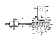
図1は操作装置10を示す。操作装置10は、基端側可動アクチュエータ14と末端すなわち遠隔側可動アクチュエータ16との間に延びる可撓性のボーデンワイヤ組体12を備える。ボーデンワイヤ組体12は、好ましくはプラスチック材料からなる外装17と、外装17の内部で移動可能なワイヤ18とを備える。ワイヤ18は末端19と基端20とを備え、それら各々は外装17の各対応端から延びる。ワイヤ18の末端19は周知のボール部材21を備え、ボール部材21は溶接等によってワイヤ末端19に固定されてワイヤ末端19を遠隔側アクチュエータ16に連結する。このように、ボール部材21は遠隔側アクチュエータ16のスロット22に取付けられ、ワイヤ18を遠隔側可動アクチュエータ16に連結する。両可動アクチュエータ14、16は、基端側部材の作動によって遠隔側部材を動かすためのあらゆる特有の操作目的に則って構成することができる。したがってアクチュエータ14、16は、ここでは概略を図示するのみに止める。
【0010】
図2〜図4を参照すると、露出したワイヤ基端20は、外装17から延び、溶接等によってワイヤ18に固定される長手方向部材すなわち溝付ロッド23を備える。溝付ロッド23は、ワイヤ基端20を基端側可動アクチュエータ14に連結するために使用される。溝付ロッド23は、軸方向に離間した複数の環状突起24を備える。それら環状突起24は、それらの間にロッド23の長さに亙って離間配置される複数の環状溝26を形成する。環状溝26は、複数の連結場所を画定するものであり、これについては後述する。
【0011】
操作装置10の基端は、ワイヤ基端20を基端側可動アクチュエータ14に連結するための板金製のクリップ28を備える。図2、図4及び図5に示すように、クリップ28は略矩形の基壁30を備える。基壁30はピン34を受容する穴32を備え、ピン34はクリップ28を可動アクチュエータ14に回転可能に連結する。基壁30の端部36には下方に突出するタブ38が設けられ、タブ38は可動アクチュエータ14へのクリップ28の組付けを容易にする。
【0012】
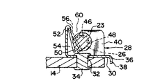
相互に略平行に離間配置された側部支持柱40、42が、基壁30から外側上方に延設される。各側部支持柱40、42は、それらを横断して延びるフランジ44と、弧状縁部48及びカム面50によって画成される掴み縁部46とを備える。カム面50は、基壁30から略上方に漸減して弧状縁部48へと円滑に推移するものであり、その作用は後述する。
【0013】
クリップ28は、基壁30から外方に側部支持柱40、42と同一方向へ、かつそれらを実質的に横断して延びる端壁52を備える。このように、基壁30、側部支持柱40、42、及び端壁52は、ワイヤ18の軸方向に延びるキャビティ54を画成する。キャビティ54は基壁30の反対側に開口する。
図示実施形態では、端壁52は、それに一体に形成された弾性カム面部材56及び58を備える。弾性カム面部材56、58は、キャビティ54内に延びてワイヤ端保持溝60を形成する。図5に示すように保持溝60は、両カム面部材56、58と両支持柱40、42との間でワイヤ18の軸方向に延在する。各弾性カム面部材56、58は、掴み縁部46に略対向して配置される。弾性カム面部材56、58は、図5に破線で示す非付勢位置から図5に実線で示す撓曲位置すなわち付勢位置へと移動可能である。非付勢位置では、溝付ロッド23の幅より小さい幅を有した保持溝が形成される。弾性カム面部材56、58は、撓曲されたときに、溝付ロッド23に対してばね力を加え、溝付ロッド23を掴み縁部46に対して保持する。これについては後述する。
【0014】
図示実施形態では、弾性カム面部材56、58は端壁52に一体的に形成される。しかしながら、各カム面部材56、58が各側部支持柱40、42に一体的に形成され、かつ端壁52が掴み縁部46を備える構成であってもよい。また、離間した側部支持柱及び離間したカム面部材が示されているが、1つの側部支持柱と、協働する1つの弾性カム面部材とを採用することもできる。
【0015】
遠隔側アクチュエータ16と基端側アクチュエータ14との間にボーデンワイヤ組体12を組付ける際は、まずボール部材21をスロット22に挿入して、ワイヤ末端19を遠隔側アクチュエータ16に連結する。次いで、ボーデンワイヤ組体12を基端側アクチュエータ14の位置に送る。そしてまず、クリップ28をピン34にて基端側アクチュエータ14に連結する。次に、ボーデンワイヤ組体12の溝付ロッド23を、それを保持溝60に挿入することによってクリップ28に取付ける。溝付ロッド23に加えられる手の力は、キャビティ54内で弾性カム面部材56、58を端壁52の方向に移動し、保持溝60を拡張する。溝付ロッド23を保持溝60内にさらに挿入すると、弾性カム面部材56、58が溝付ロッド23をカム面50に沿って押し、それにより掴み縁部46は関連する一対の溝26に係合する。このようにして、溝付ロッド23は掴み縁部46にスナップ係合し、弾性カム面部材56、58はばね力によってワイヤ基端を保持溝60内に、かつ両側部支持柱40、42の掴み縁部に対して保持する。図2に示すように、各側部支持柱40、42は、隣接する環状突起24の間に配置されるので、溝付ロッド23をワイヤ延長方向への移動に抗して保持するように構成かつ配置されるものである。また溝付ロッド23は、各掴み縁部46の弧状縁部48が溝付ロッド23の上面に係合するので、ワイヤ延長方向を横断する方向への移動が防止される。
【0016】
両掴み縁部46の間隔は、溝付ロッド23の全長よりも短い。したがって、溝付ロッド23をクリップ28に取付ける際に、溝付ロッド23を軸方向に移動しつつ所望の溝位置を選択して側部支持柱40、42の掴み縁部にスナップ係合させることにより、軸方向の長さ調整が可能となる。図2に示すように、両掴み縁部は、クリップ28を溝付ロッド23の略中央に配置した状態で、溝付ロッド23の一対の溝26に係合する。しかしながら、溝付ロッド23はクリップ28の幅を越えて延びるので、溝付ロッド23を、その軸方向長さに沿った様々な位置でクリップ28に連結されるように、クリップ28に対して位置決めすることができる。このように、ボーデンワイヤ組体の基端と基端側アクチュエータ14との連結は調整可能なものであり、ボーデンワイヤ組体の基端への基端側アクチュエータ14の連結が完了する前に、ボーデンワイヤ組体の末端に固定連結された遠隔側アクチュエータ16と、基端側アクチュエータ14との双方を適切に位置決めすることが可能になる。所望によりクリップ28を、ボーデンワイヤ組体の末端に使用することもできる。
【0017】
さらに、クリップ28の使用によりワイヤ18と基端側アクチュエータ14との連結点を調整するためのいかなる工具も不要となるので、組立作業者は、溝付ロッド23を適所に簡単にスナップ係合させるだけで一方の手のみによって組立を有利に遂行できる。このとき他方の手は空いており、必要に応じて各部品をそれらの所望位置に手で保持することができる。
【0018】
操作装置10の組立を完了する際は、保持部材64が外装17の各端部近傍でその周面に固着され、それにより外装17の基端が基端側アクチュエータ14に離間配置で固定されるとともに、外装17の末端が遠隔側アクチュエータ16に離間配置で固定される。したがって各保持部材64は、ワイヤ18が外装17内での円滑な移動を維持できるように固定対象物に連結されるべく構成かつ配置され、以て、一方のアクチュエータの動作が外装17内のワイヤ18を介して他方のアクチュエータの応答動作を引き起こすようになっている。
【0019】
上記のように、本発明の操作装置10は、車両のドア構造部においてドアをドア掛止部から掛止解除するために使用できる。したがって例えば、基端側可動アクチュエータ14の端部66を、ドアの外板を貫通する車両ドアハンドル等の手動部材(図示せず)にピン68で回動可能に連結することができる。また遠隔側アクチュエータ16の端部70は、ピン72でドア掛止機構に回動可能に連結できる。この操作装置の作動態様は以下の通りである。手動部材の手動動作は、基端側可動アクチュエータ14をピン68の周りで第1位置(図2)から回動させ、ワイヤ18に張力をかけてワイヤ18を図3の矢印A方向に移動させる。ワイヤ18の基端20における動作は、遠隔側可動アクチュエータ16の第1位置(図1)から移動位置(図示せず)への応答動作を生じさせる。遠隔側アクチュエータ16の動作は、例えば掛止機構を車両ドア掛止部から解放するために利用できる。
【0020】
このように、本発明の操作装置は、ボーデンワイヤ組体のワイヤ端を、工具を使用せずにワイヤの軸方向所望位置で可動アクチュエータに連結するための簡単かつ有効な手段を提供するものである。
本発明の目的が完全かつ効果的に達成されていることが理解されよう。しかしながら、上述した本発明の実施形態は、本発明の構造的かつ作用的原理を開示するために図示及び説明したものであり、その原理から逸脱することなく変更できる。したがって本発明は、特許請求の範囲に記載した精神に包含される全ての修正を含むものである。
【図面の簡単な説明】
【図1】本発明の原理に従って構成された操作装置を、第1の非作動位置にて示す正面図である。
【図2】図1の操作装置の基端の拡大正面図である。
【図3】図2の操作装置の基端を第2の作動位置にて示す図である。
【図4】図2の操作装置の基端の側面図である。
【図5】図2の線5−5に沿った部分断面図である。
【符号の説明】
10…操作装置
12…ボーデンワイヤ組体
14…基端側可動アクチュエータ
16…遠隔側可動アクチュエータ
17…外装
18…ワイヤ
23…溝付ロッド
24…環状突起
26…環状溝
28…クリップ
30…基壁
40、42…側部支持柱
46…掴み縁部
52…端壁
56、58…弾性カム面部材
60…保持溝[0001]
BACKGROUND OF THE INVENTION
The present invention relates to an operation device used in a vehicle such as an automobile, and relates to a remote operation device including a Bowden wire assembly installed between two movable actuators, and more particularly to a Bowden wire assembly. The present invention relates to an improved structure provided in a device for adjustably connecting each end of the body to each movable actuator.
[0002]
[Prior art]
The Bowden wire assembly is used for various operation systems in the vehicle. For example, in a vehicle door, in order to connect an inner latch release lever arranged at the front and a door latch mechanism arranged at the rear, and in a vehicle seat, an operation lever and a remote-operated adjustment mechanism Is used to link A Bowden wire assembly is typically used to operate a remote device connected to the distal end of a Bowden wire by manual operation of an actuator connected to the proximal end of the Bowden wire.
[0003]
The Bowden wire assembly includes an exterior that is fixedly attached at both ends, and a wire that can move within the exterior. In a typical configuration, the distal end of the Bowden wire assembly is coupled to a remote device and the proximal end of the Bowden wire assembly is coupled to an actuator. Due to the fixed mounting at both ends of the sheath, the movement transmitted to the proximal end of the Bowden wire assembly ensures the desired corresponding movement at the distal end of the Bowden wire assembly.
[0004]
In order to ensure that the Bowden wire assembly produces the desired operation of the remote device, the connection between the end of the Bowden wire assembly and the remote device is usually adjustable. This allows the actuator fixedly connected to the proximal end of the Bowden wire assembly and the remote device to be properly positioned before the connection of the remote device to the distal end of the Bowden wire assembly is complete. However, the proximal end may be an adjustable end.
[0005]
A typical configuration for making the adjustment is to attach a cylindrical member to the remote device. The cylindrical member includes an axial bore that receives the end of the Bowden wire assembly, and a screw hole that extends radially inward from the peripheral surface of the cylindrical member and communicates with the axial bore. At this time, the set screw is engaged with the screw hole, and after the end of the Bowden wire assembly is properly positioned in the bore, the set screw can be turned to be gripped and engaged with the end of the Bowden wire assembly.
[0006]
[Problems to be solved by the invention]
The problem with this type of adjustment is that it is difficult to screw the set screw with a tool while holding the parts in their desired positions by hand.
An object of the present invention is to provide an operation comprising a Bowden wire assembly and means for connecting one end of the Bowden wire assembly to a movable actuator at a selectable position and using a simple manual operation without using a tool. To provide an apparatus.
[0007]
[Means for Solving the Problems]
In order to achieve the above object, the present invention provides a flexible sheath including an exterior and a wire that is movably installed in the exterior and extends and exposes a proximal end and a distal end from the proximal end and the distal end of the exterior, respectively. A Bowden wire assembly, a first actuator installed to operate at a first location, and a second actuator installed to operate at a remote second location, wherein the exterior includes the first location and the second location And a remote end fixed to the first actuator in a spaced arrangement and a remote end fixed to the second actuator in a spaced arrangement are provided. In this remote control device, one end of the Bowden wire assembly is connected to one of the first and second actuators. The other end of the Bowden wire includes an extending member that is fixed to the other end and extends in the axial direction from the other end. The elongate member has a series of annular grooves formed in an axially spaced arrangement on its outer peripheral surface. On the other of the first and second actuators, a clip configured and arranged to receive and hold the extension member at a selected position adjusted in the relative axial direction is rotatably attached. The clip is formed of sheet metal and has a base wall connected to the other actuator, first and second support walls extending away from the base wall, and extending outward from the base wall. And an end wall disposed substantially transverse to the first and second support walls. The base wall, support wall and end wall are constructed and arranged to define a cavity extending in the axial direction of the wire and opening on the opposite side of the base wall. The end wall includes an elastic cam surface structure formed integrally therewith, and the cam surface structure extends into the cavity and defines a retaining groove between the cam surface structure and the first and second support walls. . The first and second support walls define a pair of spaced gripping edges, the gripping edges corresponding to one of the series of annular grooves at a selected axial position relative to the elongate member. Engage with surfaces defining a pair of annular grooves. The width of the holding groove is smaller than the width of the extension member when the elastic cam surface structure is in the non-biased state, and is expandable when the elastic cam surface structure moves to the biased state within the cavity. The member is placed in the extended holding groove and receives a spring force in a direction transverse to the wire axial direction from the elastic cam surface structure so that the gripping edge has a pair of annular grooves at the selected axial position. Engage with the defining surface to hold the elongate member against movement in the wire extension direction.
[0008]
Another object of the present invention is to provide an operating device of the type described above that operates effectively with a simple structure and is economical to manufacture and maintain. These and other objects of the invention will be apparent from the detailed description and claims that follow.
[0009]
DETAILED DESCRIPTION OF THE INVENTION
FIG. 1 shows an operating device 10. The operating device 10 includes a flexible Bowden
[0010]
2-4, the exposed wire
[0011]
The proximal end of the operating device 10 includes a
[0012]
[0013]
In the illustrated embodiment, the
[0014]
In the illustrated embodiment, the elastic
[0015]
When the
[0016]
The distance between the
[0017]
Further, since the use of the
[0018]
When the assembly of the operation device 10 is completed, the holding
[0019]
As described above, the operating device 10 of the present invention can be used to unlock the door from the door latching portion in the door structure portion of the vehicle. Therefore, for example, the
[0020]
Thus, the operating device of the present invention provides a simple and effective means for connecting the wire end of the Bowden wire assembly to the movable actuator at a desired position in the axial direction of the wire without using a tool. is there.
It will be appreciated that the objects of the invention have been achieved completely and effectively. However, the above-described embodiments of the present invention have been illustrated and described in order to disclose the structural and operational principles of the present invention and may be modified without departing from the principles. Accordingly, this invention includes all modifications encompassed within the spirit of the claims.
[Brief description of the drawings]
FIG. 1 is a front view of an operating device constructed in accordance with the principles of the present invention in a first inoperative position.
FIG. 2 is an enlarged front view of a proximal end of the operating device in FIG. 1;
FIG. 3 is a diagram showing a proximal end of the operating device of FIG. 2 in a second operating position.
4 is a side view of the proximal end of the operating device of FIG. 2;
FIG. 5 is a partial cross-sectional view taken along line 5-5 of FIG.
[Explanation of symbols]
DESCRIPTION OF SYMBOLS 10 ...
Claims (8)
第1場所で動作するように設置された第1アクチュエータ、及び
遠隔の第2場所で動作するように設置された第2アクチュエータ、
を具備し、
前記外装は、前記第1場所と前記第2場所との間に延び、前記第1アクチュエータに離間配置で固定される基端と前記第2アクチュエータに離間配置で固定される遠隔端とを備え、
前記ボーデンワイヤ組体の一端は、前記第1及び第2アクチュエータのいずれか一方に連結され、
前記ボーデンワイヤの他端は、該他端に固定されて該他端から軸方向へ延びる伸長部材を備え、該伸長部材が、その外周面に軸方向離間配置で形成された一連の環状溝を有し、
前記第1及び第2アクチュエータの他方には、相対的軸方向調整した選択された位置で前記伸長部材を受容保持するように構成、配置されたクリップが回動可能に取付けられ、
該クリップは、板金から形成されるとともに、
前記他方のアクチュエータに連結される基壁、
該基壁から外方へ相互離間して延びる第1及び第2の支持壁、及び
該基壁から外方へ延び、前記第1及び第2の支持壁を略横断して配置される端壁を備え、それら基壁、支持壁及び端壁が、ワイヤの軸方向に延びて該基壁の反対側で開口するキャビティを画成するように構成、配置され、
前記端壁は、それに一体的に形成された弾性カム面構造を備え、該カム面構造は前記キャビティ内に延びて該カム面構造と前記第1及び第2の支持壁との間に保持溝を画成し、
前記第1及び第2の支持壁は、相互離間した一対の掴み縁部を画成し、それら掴み縁部は、前記伸長部材に対して選択された軸方向位置で前記一連の環状溝のうちの対応する一対の環状溝を画成する面に係合し、
前記保持溝の幅は、前記弾性カム面構造が非付勢状態にあるときに前記伸長部材の幅よりも小さく、かつ該カム面構造が前記キャビティ内で付勢状態に移動する際に拡張可能であり、前記伸長部材は、拡張された該保持溝内に配置されて該カム面構造からワイヤ軸方向を横断する方向へばね力を受け、以て前記掴み縁部が、前記選択された軸方向位置で一対の環状溝を画成する面に係合して、該伸長部材をワイヤ延長方向への移動に対して保持する、
ように構成された車両用遠隔操作装置。A flexible Bowden wire assembly comprising: an outer sheath; and a wire that is movably installed in the outer sheath and extends and exposes a base end and a distal end from the base end and the distal end of the sheath, respectively
A first actuator installed to operate at a first location, and a second actuator installed to operate at a remote second location;
Comprising
The exterior includes a proximal end that extends between the first location and the second location and is secured to the first actuator in a spaced configuration and a remote end secured to the second actuator in a spaced configuration,
One end of the Bowden wire assembly is connected to one of the first and second actuators,
The other end of the Bowden wire includes an extension member fixed to the other end and extending in the axial direction from the other end. Have
A clip configured and arranged to receive and hold the elongate member at a selected position adjusted relative to the axial direction is rotatably attached to the other of the first and second actuators,
The clip is formed from sheet metal and
A base wall connected to the other actuator;
First and second support walls extending outwardly from the base wall and end walls extending outwardly from the base wall and disposed substantially transversely to the first and second support walls The base wall, the support wall and the end wall are configured and arranged to define a cavity extending in the axial direction of the wire and opening on the opposite side of the base wall;
The end wall includes an elastic cam surface structure formed integrally therewith, and the cam surface structure extends into the cavity, and a holding groove is formed between the cam surface structure and the first and second support walls. To define
The first and second support walls define a pair of spaced gripping edges, the gripping edges of the series of annular grooves at a selected axial position relative to the elongate member. Engaging a corresponding surface defining a pair of annular grooves,
The width of the holding groove is smaller than the width of the extension member when the elastic cam surface structure is in the non-biased state, and can be expanded when the cam surface structure moves to the biased state within the cavity. The elongate member is disposed in the extended holding groove and receives a spring force from the cam surface structure in a direction transverse to the wire axial direction, so that the gripping edge is the selected shaft. Engaging a surface defining a pair of annular grooves at a directional position to hold the elongated member against movement in the wire extension direction;
The vehicle remote control device configured as described above.
Applications Claiming Priority (2)
| Application Number | Priority Date | Filing Date | Title |
|---|---|---|---|
| US08/299,645 US5511442A (en) | 1994-09-02 | 1994-09-02 | Control system with bowden wire assembly end clip |
| US299645 | 1994-09-02 |
Publications (2)
| Publication Number | Publication Date |
|---|---|
| JPH08194555A JPH08194555A (en) | 1996-07-30 |
| JP3607376B2 true JP3607376B2 (en) | 2005-01-05 |
Family
ID=23155666
Family Applications (1)
| Application Number | Title | Priority Date | Filing Date |
|---|---|---|---|
| JP22191595A Expired - Fee Related JP3607376B2 (en) | 1994-09-02 | 1995-08-30 | Remote control device for vehicle |
Country Status (9)
| Country | Link |
|---|---|
| US (1) | US5511442A (en) |
| EP (1) | EP0699841B1 (en) |
| JP (1) | JP3607376B2 (en) |
| KR (1) | KR100347877B1 (en) |
| AT (1) | ATE193357T1 (en) |
| AU (1) | AU682614B2 (en) |
| CA (1) | CA2154417A1 (en) |
| DE (1) | DE69517108T2 (en) |
| ES (1) | ES2145873T3 (en) |
Families Citing this family (25)
| Publication number | Priority date | Publication date | Assignee | Title |
|---|---|---|---|---|
| DE4420626C2 (en) * | 1994-06-14 | 1998-12-17 | Grammer Ag | Last actuating device for a vehicle seat |
| ES2176554T3 (en) * | 1997-05-16 | 2002-12-01 | Advanced Elastomer Systems | METHOD FOR WELDING WITH HIGH FREQUENCY ELASTOMEROS NON-POLAR THERMOPLASTICS. |
| US6975219B2 (en) * | 2001-03-01 | 2005-12-13 | Fisher-Rosemount Systems, Inc. | Enhanced hart device alerts in a process control system |
| US7206646B2 (en) * | 1999-02-22 | 2007-04-17 | Fisher-Rosemount Systems, Inc. | Method and apparatus for performing a function in a plant using process performance monitoring with process equipment monitoring and control |
| US8044793B2 (en) * | 2001-03-01 | 2011-10-25 | Fisher-Rosemount Systems, Inc. | Integrated device alerts in a process control system |
| US7562135B2 (en) * | 2000-05-23 | 2009-07-14 | Fisher-Rosemount Systems, Inc. | Enhanced fieldbus device alerts in a process control system |
| US6301992B1 (en) * | 1999-07-22 | 2001-10-16 | Paolo Paparoni | Adjustment and assembly system for mechanical cable remote control |
| US7720727B2 (en) | 2001-03-01 | 2010-05-18 | Fisher-Rosemount Systems, Inc. | Economic calculations in process control system |
| US8073967B2 (en) | 2002-04-15 | 2011-12-06 | Fisher-Rosemount Systems, Inc. | Web services-based communications for use with process control systems |
| US6965806B2 (en) * | 2001-03-01 | 2005-11-15 | Fisher-Rosemount Systems Inc. | Automatic work order/parts order generation and tracking |
| DE60206884T2 (en) * | 2001-03-01 | 2006-07-27 | Fisher-Rosemount Systems, Inc., Austin | Sharing of data in the process plant |
| US9201420B2 (en) | 2005-04-08 | 2015-12-01 | Rosemount, Inc. | Method and apparatus for performing a function in a process plant using monitoring data with criticality evaluation data |
| US8005647B2 (en) | 2005-04-08 | 2011-08-23 | Rosemount, Inc. | Method and apparatus for monitoring and performing corrective measures in a process plant using monitoring data with corrective measures data |
| US7272531B2 (en) * | 2005-09-20 | 2007-09-18 | Fisher-Rosemount Systems, Inc. | Aggregation of asset use indices within a process plant |
| US8301676B2 (en) | 2007-08-23 | 2012-10-30 | Fisher-Rosemount Systems, Inc. | Field device with capability of calculating digital filter coefficients |
| US7702401B2 (en) | 2007-09-05 | 2010-04-20 | Fisher-Rosemount Systems, Inc. | System for preserving and displaying process control data associated with an abnormal situation |
| US8055479B2 (en) | 2007-10-10 | 2011-11-08 | Fisher-Rosemount Systems, Inc. | Simplified algorithm for abnormal situation prevention in load following applications including plugged line diagnostics in a dynamic process |
| EP2473724B1 (en) | 2009-09-03 | 2014-04-23 | Volkswagen Aktiengesellschaft | By-pass arrangement for a turbo charger |
| DE102009054241A1 (en) * | 2009-11-21 | 2011-05-26 | Volkswagen Ag | Actuator assembling and adjusting method for exhaust gas turbocharger of internal combustion engine, involves applying force to actuator in relative position by tool, where position is arranged between actuating section and adjusting bar |
| US9927788B2 (en) | 2011-05-19 | 2018-03-27 | Fisher-Rosemount Systems, Inc. | Software lockout coordination between a process control system and an asset management system |
| JP5392327B2 (en) * | 2011-09-11 | 2014-01-22 | 日産自動車株式会社 | Intermediate gripping tool for charging cable |
| US9447737B2 (en) * | 2013-06-14 | 2016-09-20 | Walbro Llc | Throttle cable retainer |
| CN104029669A (en) * | 2014-06-28 | 2014-09-10 | 柳州市二和汽车零部件有限公司 | Automotive brake cable |
| JP6891476B2 (en) * | 2016-12-15 | 2021-06-18 | いすゞ自動車株式会社 | Accelerator wire adjustment mechanism |
| DE102017208277B4 (en) * | 2017-05-17 | 2021-02-11 | Vitesco Technologies Germany Gmbh | Cable device and parking lock |
Family Cites Families (13)
| Publication number | Priority date | Publication date | Assignee | Title |
|---|---|---|---|---|
| FR1377924A (en) * | 1963-12-24 | 1964-11-06 | United Carr Fastener Corp | Cable tie especially for bowden cables |
| FR1377947A (en) * | 1963-12-26 | 1964-11-06 | United Carr Fastener Corp | Cable tie for bowden cable or similar |
| US3513718A (en) * | 1968-02-15 | 1970-05-26 | Jerry J Tomecek | Control system adjustment means |
| US4185515A (en) * | 1974-10-11 | 1980-01-29 | Teleflex Incorporated | Motion transmitting remote control assembly |
| US4244238A (en) * | 1976-12-17 | 1981-01-13 | Toyota Jidosha Kogyo Kabushiki Kaisha | Remote control wire apparatus |
| GB2195161A (en) * | 1986-09-12 | 1988-03-30 | Ford Motor Co | Cable clip |
| US5074162A (en) * | 1990-03-14 | 1991-12-24 | Teleflex Incorporated | Local station clutch |
| US5230257A (en) * | 1991-11-07 | 1993-07-27 | Teleflex Incorporated | Remote control assembly with snap-in terminal |
| FR2686663B1 (en) * | 1992-01-23 | 1996-06-28 | Fabrication Indle Ste Europ | DEVICE FOR ADJUSTING THE POSITION OF AN END OF A SHEATH CONTAINING A CONTROL CABLE. |
| US5207116A (en) * | 1992-02-25 | 1993-05-04 | General Motors Corporation | Cable core length adjuster mechanism |
| US5295408A (en) * | 1992-10-09 | 1994-03-22 | Nagle Industries, Inc. | Adjustable cable strand end fitting |
| AU663016B2 (en) * | 1992-11-30 | 1995-09-21 | E.P. Stelling | Bowden cable push button actuator |
| US5394770A (en) * | 1993-04-08 | 1995-03-07 | Telflex Incorporated | Core length adjuster |
-
1994
- 1994-09-02 US US08/299,645 patent/US5511442A/en not_active Expired - Lifetime
-
1995
- 1995-07-21 CA CA002154417A patent/CA2154417A1/en not_active Abandoned
- 1995-07-25 AU AU27154/95A patent/AU682614B2/en not_active Ceased
- 1995-08-10 KR KR1019950024738A patent/KR100347877B1/en not_active IP Right Cessation
- 1995-08-30 JP JP22191595A patent/JP3607376B2/en not_active Expired - Fee Related
- 1995-09-01 DE DE69517108T patent/DE69517108T2/en not_active Expired - Fee Related
- 1995-09-01 ES ES95306149T patent/ES2145873T3/en not_active Expired - Lifetime
- 1995-09-01 EP EP95306149A patent/EP0699841B1/en not_active Expired - Lifetime
- 1995-09-01 AT AT95306149T patent/ATE193357T1/en not_active IP Right Cessation
Also Published As
| Publication number | Publication date |
|---|---|
| EP0699841A1 (en) | 1996-03-06 |
| EP0699841B1 (en) | 2000-05-24 |
| ATE193357T1 (en) | 2000-06-15 |
| JPH08194555A (en) | 1996-07-30 |
| AU682614B2 (en) | 1997-10-09 |
| CA2154417A1 (en) | 1996-03-03 |
| US5511442A (en) | 1996-04-30 |
| DE69517108D1 (en) | 2000-06-29 |
| AU2715495A (en) | 1996-03-14 |
| KR960013123A (en) | 1996-04-20 |
| ES2145873T3 (en) | 2000-07-16 |
| DE69517108T2 (en) | 2000-09-28 |
| KR100347877B1 (en) | 2002-11-29 |
Similar Documents
| Publication | Publication Date | Title |
|---|---|---|
| JP3607376B2 (en) | Remote control device for vehicle | |
| JP4245766B2 (en) | Means for securing the elongated member | |
| JP2001114020A (en) | Trailer toe mirror | |
| KR970706986A (en) | Adjustable truck rearview mirror (ADJUSTABLE TRUCK MIRROR) | |
| JPH09170618A (en) | Large coercive-force n snap slid by small force | |
| JPS63266510A (en) | Remote control mechanism | |
| US4069721A (en) | Mechanism for joining a cable to a link lever | |
| JPH0366883B2 (en) | ||
| JPH0750569Y2 (en) | Control cable clamp device | |
| KR960014720A (en) | Device inserted into automatic gear lever joint mechanism driven by cable | |
| JPH0378487B2 (en) | ||
| EP0778176A3 (en) | Cancellation device for turn signal switch | |
| KR200221356Y1 (en) | Fastening clip | |
| CA1089310A (en) | Traction device for use with a thomas splint | |
| JPH0137945B2 (en) | ||
| KR19990001818A (en) | Automatic play adjustment of clutch cable | |
| JPH0623659Y2 (en) | Door handle device for automobile | |
| KR200213848Y1 (en) | Seat position adjustment structure of car | |
| JPH0562296A (en) | Device for attaching hand-brake | |
| JPH09290686A (en) | Assembly method of cable type mirror control device | |
| JPH08291819A (en) | Cable incorporating mechanism | |
| JPH0129740B2 (en) | ||
| JP2936049B2 (en) | Lever mounting structure for operation lever device | |
| KR950013863A (en) | Tension adjusting device for parking brake | |
| JPS61297040A (en) | Method and device for incorporating spring member |
Legal Events
| Date | Code | Title | Description |
|---|---|---|---|
| TRDD | Decision of grant or rejection written | ||
| A01 | Written decision to grant a patent or to grant a registration (utility model) |
Free format text: JAPANESE INTERMEDIATE CODE: A01 Effective date: 20040907 |
|
| A61 | First payment of annual fees (during grant procedure) |
Free format text: JAPANESE INTERMEDIATE CODE: A61 Effective date: 20041007 |
|
| R150 | Certificate of patent or registration of utility model |
Free format text: JAPANESE INTERMEDIATE CODE: R150 |
|
| FPAY | Renewal fee payment (event date is renewal date of database) |
Free format text: PAYMENT UNTIL: 20071015 Year of fee payment: 3 |
|
| FPAY | Renewal fee payment (event date is renewal date of database) |
Free format text: PAYMENT UNTIL: 20081015 Year of fee payment: 4 |
|
| LAPS | Cancellation because of no payment of annual fees |