JP3607096B2 - Auxiliary cooling system for nuclear power plant - Google Patents
Auxiliary cooling system for nuclear power plant Download PDFInfo
- Publication number
- JP3607096B2 JP3607096B2 JP29660198A JP29660198A JP3607096B2 JP 3607096 B2 JP3607096 B2 JP 3607096B2 JP 29660198 A JP29660198 A JP 29660198A JP 29660198 A JP29660198 A JP 29660198A JP 3607096 B2 JP3607096 B2 JP 3607096B2
- Authority
- JP
- Japan
- Prior art keywords
- cooling water
- emergency
- equipment
- normal
- cooling
- Prior art date
- Legal status (The legal status is an assumption and is not a legal conclusion. Google has not performed a legal analysis and makes no representation as to the accuracy of the status listed.)
- Expired - Fee Related
Links
Images

Classifications
-
- Y—GENERAL TAGGING OF NEW TECHNOLOGICAL DEVELOPMENTS; GENERAL TAGGING OF CROSS-SECTIONAL TECHNOLOGIES SPANNING OVER SEVERAL SECTIONS OF THE IPC; TECHNICAL SUBJECTS COVERED BY FORMER USPC CROSS-REFERENCE ART COLLECTIONS [XRACs] AND DIGESTS
- Y02—TECHNOLOGIES OR APPLICATIONS FOR MITIGATION OR ADAPTATION AGAINST CLIMATE CHANGE
- Y02E—REDUCTION OF GREENHOUSE GAS [GHG] EMISSIONS, RELATED TO ENERGY GENERATION, TRANSMISSION OR DISTRIBUTION
- Y02E30/00—Energy generation of nuclear origin
Landscapes
- Structure Of Emergency Protection For Nuclear Reactors (AREA)
Description
【0001】
【発明の属する技術分野】
本発明は、原子力発電所に設置されている非常用機器と常・非常用機器及び通常運転に必要な常用機器で発生する熱を、最終的な排熱場所の海や河川、あるいは湖や大気等に放出させるための原子力発電所の補機冷却装置に関する。
【0002】
【従来の技術】
原子力発電所における補機冷却装置は、淡水ループの補機冷却水系と海水系の補機冷却海水系等で構成されており、原子力発電所に設置されている非常用機器と常・非常用機器及び原子力発電所の通常運転に必要な常用機器で発生する熱を最終的な排熱場所である海等に放出するために設置されている。
【0003】
従って、この補機冷却装置は、熱交換器及び冷却水供給配管と、熱交換した冷却水を熱交換器へ戻す冷却水戻り配管及び冷却水戻り配管に設けられた冷却水ポンプよりなる閉ループの淡水系の補機冷却水系と、前記熱交換器にそれぞれ、例えば、冷却海水を供給する海水ポンプ及び冷却海水供給配管を接続して、熱交換した冷却海水を海に戻す放水配管からなる海水系の補機冷却海水系で構成される系統が3系統にて構成している。
【0004】
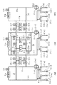
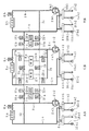
この補機冷却装置については、図7の系統構成図に示すように、左からA,C,Bの3系統はいずれもほぼ同じ構成で、補機冷却水系の冷却水が循環する冷却水供給配管1a〜1cと、2重化した冷却水ポンプ2a1 ,2a2 〜2c1 ,2c2 を直列にした冷却水戻り配管3a〜3cは、2重化した熱交換器4a1 ,4a2 〜4c1 ,4c2 が接続されている。
【0005】
前記冷却水供給配管1a〜1cと冷却水戻り配管3a〜3cとの間に、冷却対象負荷である非常用機器5a〜5cと直列に非常用機器出口弁6a〜6cが接続されており、また、A,Cの2系統の冷却水供給配管1a,1cと冷却水戻り配管3a,3cの間には、常・非常用機器7a,7bが接続されている。
【0006】
さらに、前記冷却水供給配管1a〜1cと冷却水戻り配管3a〜3cとの間に、常用機器8a〜8cを両側に常用機器隔離弁9a〜9c,10a〜10cを介して接続している。
また、前記常用機器8a〜8cの両端は、供給タイライン元弁11a〜11cと戻りタイライン元弁12a〜12cを介して、A〜Cの3系統を連絡する冷却水供給タイライン13及び冷却水戻りタイライン14に接続されて、全体として淡水系の閉ループを構成している。
【0007】
なお、排熱場所を例えば海とした、海水系の補機冷却海水系については、前記熱交換器4a1 ,4a2 〜4c1 ,4c2 には、海水ポンプ15a1 ,15a2 〜15c1 ,15c2 を介挿した冷却海水供給配管16a1 ,16a2 〜16c1 ,16c2 と、放水配管17a1 ,17a2 〜17c1 ,17c2 が接続されている。
【0008】
このように、3系統で構成された補機冷却装置については、事故時において設計上で非常用機器5a〜5cの除熱性能として、A〜Cの各系統とも50%の除熱能力を有している。
即ち、3系統のうち2系統にて所要除熱能力を満足する冗長化した設計で、これにより、1系統が何らかの事象により故障した場合でも、残りの2系統の設備で冷却機能を満足させるという、原子力プラントにおける安全設計の基本的な考え方の、単一故障基準に従っているものである。
【0009】
このように構成された補機冷却装置では、冷却水ポンプ2a1 ,2a2 〜2c1 ,2c2 により、冷却水供給配管1a〜1c及び冷却水戻り配管2a〜2c内を循環する冷却水は、熱交換器4a1 ,4a2 〜4c1 ,4c2 で冷却され、冷却水供給配管1a〜1cを介して冷却対象負荷である非常用機器5a〜5cと、常・非常用機器7a,7b及び常用機器8a〜8cに供給される。
【0010】
これら冷却対象負荷を冷却して昇温した冷却水は、それぞれ、冷却水戻り配管3a〜3cと冷却水ポンプ2a1 ,2a2 〜2c1 ,2c2 を介して、再び熱交換器4a1 ,4a2 〜4c1 ,4c2 に戻される。
熱交換器4a1 ,4a2 〜4c1 ,4c2 では、昇温された冷却水が海水ポンプ15a1 ,15a2 〜15c1 ,15c2 により、冷却海水供給配管16a1 ,16a2 〜16c1 ,16c2 を介して供給される海水と熱交換され、再び冷却水となると共に昇温された海水は、放水配管17a1 ,17a2 〜17c1 ,17c2 より最終的な排熱場所である海に放出される。
【0011】
なお、この補機冷却海水設備では、通常運転中は各系統共に海水ポンプ1台(例えば15a1 ,15b1 ,15c1 )と、熱交換器1基(例えば4a1 ,4b1 ,4c1 )が運転される。
また、事故時においては、各系統共に海水ポンプ2台(15a1 ,15a2 〜15c1 ,15c2 )と、熱交換器2基(4a1 ,4a2 〜4c1 ,4c2 )の全台が運転される。
【0012】
なお、原子力発電所の定期検査時においては、3系統の補機冷却系の内1系統ずつを停止して、冷却水ポンプ2a1 ,2a2 〜2c1 ,2c2 、海水ポンプ15a1 ,15a2 〜15c1 ,15c2 、熱交換器4a1 ,4a2 〜4c1 ,4c2 等の保守点検を実施する。
【0013】
この時も常用機器8a〜8c及び常・非常用機器7a,7bに対する冷却は、停止することができないために、運転中の2系統の内任意の1系統から冷却水供給タイライン13と冷却水戻りタイライン14を運用して、停止している系統の常用機器8a〜8c及び常・非常用機器7a,7bへ冷却水を供給する。
従って、原子力発電所の定期検査中は、運転している2系統については共にポンプ2台、熱交換器2基の全台運転となっている。
【0014】
【発明が解決しようとする課題】
上記した従来の補機冷却装置においては、3系統の補機冷却系に非常用機器5a〜5cと、常・非常用機器7a,7b及び常用機器8a〜8cを、それぞれ配分して系統を構成しており、個々の機器の冷却水量及び除熱負荷要求について、非常用機器5a〜5cは系統毎に要求容量がほぼ同じである。
【0015】
しかしながら、常・非常用機器7a,7bは、要求冷却源が2区分のみであり、また常用機器8a〜8cについては、個々の負荷容量が異なるために、適切に3等分することは困難であった。
従って、必要容量に対して冷却水ポンプ2a1 ,2a2 〜2c1 ,2c2 と海水ポンプ15a1 ,15a2 〜15c1 ,15c2 、及び熱交換器4a1 ,4a2 〜4c1 ,4c2 の余裕がアンバランスになったり、A〜C系統毎に冷却水ポンプや海水ポンプ及び熱交換器の仕様を異ならせたりする必要があった。
【0016】
このために、定期検査時の冷却水供給タイライン13と冷却水戻りタイライン14を介して行うタイライン運転に際しても、A〜C各系統の機器容量及び負荷容量がまちまちで、全てのバックアップ運転モード毎に容量の確認を行う必要があった。
さらに補機冷却装置は、1系統当たり2台の冷却水ポンプ2a1 ,2a2 〜2c1 ,2c2 と、2台の海水ポンプ15a1 ,15a2 〜15c1 ,15c2 、及び2基の熱交換器4a1 ,4a2 〜4c1 ,4c2 で構成している。
【0017】
しかしながら、各系統で全台運転するのは事故時及び原子炉停止時のみであり、通常運転中はそれぞれ1台の冷却水ポンプ(例えば、2a1 ,2b1 ,2c1 )、1台の海水ポンプ(例えば、15a1 ,15b1 ,15c1 )、1基の熱交換器(例えば4a1 ,4b1 ,4c1 )のみが運用されている。
【0018】
従って、残りの1台の冷却水ポンプ(例えば、2a2 ,2b2 ,2c2 )、1台の海水ポンプ(例えば、15a2 ,15b2 ,15c2 )、1基の熱交換器(例えば4a2 ,4b2 ,4c2 )は待機状態となっている。このために、何れの系統についても通常運転中は系統停止をさせることができなかった。
【0019】
本発明の目的とするところは、冷却系統を原子力発電所の安全分離区分に従い3系統にすると共に、常・非常用機器及び常用機器を2系統に分割して、通常運転や定期検査及び事故時の運転モードに応じて、2乃至3系統により冷却を行う原子力発電所の補機冷却装置を提供することにある。
【0020】
【課題を解決するための手段】
上記目的を達成するため請求項1記載の発明に係る原子力発電所の補機冷却装置は、原子力発電所の安全分離区分に従った第1,第2,第3の3系統とした系統が、非常用機器と、常・非常用機器と、常用機器と、これらの機器の除熱に供される冷却水を供給する冷却水ポンプと、前記冷却水と外部低熱源と熱交換するために熱交換器とを有する原子力発電所の補機冷却装置において、前記第1の系統の冷却水ポンプの吐出側と前記第1の系統の非常用機器を接続する第1の系統の冷却水供給配管から分岐して前記第2の系統の冷却水ポンプの吐出側と前記第2の系統の非常用機器を接続する第2の冷却水供給配管へ接続される冷却水供給タイラインと、前記第3の系統の冷却水ポンプの吐出側と前記第3の系統の非常用機器を接続する第3の冷却水供給配管から分岐して前記冷却水供給タイラインへ接続される常用供給ラインと、前記第1の系統の冷却水ポンプの吸込側と前記第1の非常用機器を接続する第1の冷却水戻り配管から分岐して前記第2の系統の冷却水ポンプの吸込側と前記第2の非常用機器を接続する第2の冷却水戻り配管へ接続される冷却水戻りタイラインと、前記第3の系統の冷却水ポンプの吸込側と前記第3の系統の非常用機器を接続する第3の冷却水戻り配管から分岐して前記冷却水戻りタイラインへ接続される常用戻りラインと、前記冷却水供給タイラインから分岐して冷却水戻りタイラインに接続される複数の並列配管上に前記常・非常用機器と常用機器とを設けたことを特徴とする。
【0021】
各種弁の運用により通常運転及び定期検査中には、3系統の内の2系統を運転して各系統の常・非常用機器及び常用機器へ冷却水を供給して冷却を行い、1系統を待機あるいは保守をすることができる。また事故時には、3系統を共に運転して非常用機器及び常・非常用機器へ冷却水を供給する。
【0022】
請求項2記載の発明に係る原子力発電所の補機冷却装置は、請求項1において、冷却水供給タイラインと冷却水戻りタイラインに並列に接続された複数の常・非常用機器、常用機器のうち、常・非常用機器は前記タイラインの2つの端部に設けられた前記並列配管上にそれぞれ1系統設けられており、前記2つの端部に設けられた並列配管と前記冷却水供給タイラインの接続点と前記常用機器が設けられている並列配管と冷却水供給タイラインの接続点との間および前記2つの端部に設けられた前記並列配管と前記冷却水戻りタイラインの接続点と前記常用機器が設けられている並列配管と冷却水戻りタイラインの接続点との間に前記常・非常用機器を隔離可能に常・非常用機器隔離弁を設けたことを特徴とする。
【0023】
3つの冷却系統に対して常・非常用機器が2系統に分割されているので、通常運転中は各常・非常用機器と接続した冷却水供給配管に設けたモード弁の運用により、2系統から常・非常用機器に冷却水を供給して冷却を行う。
また、事故時には隔離弁の運用により特定の2系統から冷却水を供給して冷却を行う。
【0024】
請求項3記載の発明に係る原子力発電所の補機冷却装置は、請求項2において、常用機器を隔離可能に前記常用供給ラインおよび常用戻りラインに常用機器隔離弁を設けたことを特徴とする。
【0025】
3つの冷却系統に対して常用機器が2系統に分割されているので、各常用機器と接続した冷却水供給配管に設けたモード弁の運用により、2系統から常用機器に冷却水を供給して冷却を行う。
また、事故時には隔離弁の運用により特定の2系統から冷却水を供給して冷却を行う。
【0026】
【発明の実施の形態】
本発明の一実施の形態について図面を参照して説明する。なお、上記した従来技術と同じ構成部分については、同一符号を付して詳細な説明を省略する。
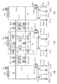
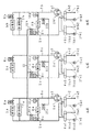
原子力発電所の補機冷却装置は図1の系統構成図に示すように、左からA系(第1の系統)、C系(第3の系統)、B系(第2の系統)とする3系統からなり、補機冷却水系の淡水による冷却水が循環する冷却水供給配管1a〜1cと、2重化した冷却水ポンプ2a1 ,2a2 〜2c1 ,2c2 を直列にした冷却水戻り配管3a〜3cが、2重化した熱交換器4a1 ,4a2 〜4c1 ,4c2 に接続されている。
【0027】
前記冷却水供給配管1a〜1cと冷却水戻り配管3a〜3cとの間には、冷却対象負荷である非常用機器5a〜5cと非常用機器出口弁6a〜6cが直列に接続されていて、全体としてそれぞれ閉ループを構成している。
また、A系とB系の冷却水供給配管1a,1bと冷却水戻り配管3a,3bの間には、冷却水供給タイライン13及び冷却水戻りタイライン14を接続してA系とB系を連絡している(請求項1)。
【0028】
なお、前記冷却水供給タイライン13においては、A系側にA系モード弁18aとA系隔離弁19aが、中央には常用系モード弁20が、B系側にはB系隔離弁19bとB系モード弁18bが介挿されている。
また、冷却水戻りタイライン14については、A系側にA系モード弁21aとA系隔離弁22aが、中央には常用系モード弁23が、B系側にB系隔離弁22bとB系モード弁21bが介挿されている。
【0029】
さらに、前記冷却水供給タイライン13及び冷却水戻りタイライン14との間で、前記A系モード弁18aとA系隔離弁19aの間、A系モード弁21aとA系隔離弁22aとの間に、常・非常用機器7aが常・非常用ライン24aで接続している。
また、B系隔離弁19bとB系モード弁18bの間とB系隔離弁22bとB系モード弁21bとの間に常・非常用機器7bを常・非常用ライン24bにより接続されている(請求項2)。
【0030】
前記冷却水供給タイライン13と冷却水戻りタイライン14の間で、前記常用系モード弁20と常用系モード弁23を挟んで、2区分に分割した常用機器8d,8eを、それぞれ常用ライン25a,25bにより接続する(請求項3)。
【0031】
なお、前記常用ライン25a,25bの冷却水供給タイライン13側には、前記冷却水供給配管1cから常用供給ライン26を介して、C系第1隔離弁27a,27bが接続され、前記常用ライン25a,25bの冷却水戻りタイライン14側には、前記冷却水戻り配管3cから常用戻りライン28を介して、C系第2隔離弁29a,29bを接続している。
【0032】
さらに、排熱場所を例えば海とした、海水系の補機冷却海水系については、前記熱交換器4a1 ,4a2 〜4c1 ,4c2 には、海水ポンプ15a1 ,15a2 〜15c1 ,15c2 を介挿した冷却海水供給配管16a1 ,16a2 〜16c1 ,16c2 と、放水配管17a1 ,17a2 〜17c1 ,17c2 が接続して構成されている。
【0033】
次に、上記構成による作用について説明する。原子力発電所の各運転状態における補機冷却装置の運転モードについて、図2乃至図6の運転モード系統模式図に示し、この時の冷却水の流れを太線で表している。
図2は第1の通常運転状態であり、A系とB系により常・非常用機器7aと常用機器8d、及び常・非常用機器7bと常用機器8eの冷却を行う運転状態の場合を示す。
従って、A系、B系とも冷却水ポンプ2a1 ,2a2 ,2b1 ,2b2 と、海水ポンプ15a1 ,15a2 ,15b1 ,15b2 及び熱交換器4a1 ,4a2 ,4b1 ,4b2 を全台運転するが、C系の冷却水ポンプ2c1 ,2c2 と海水ポンプ15c1 ,15c2 、及び熱交換器4c1 ,4c1 は全て停止状態にされる。
【0034】
これには、C系第1隔離弁27a,27bとC系第2隔離弁29a,29bを閉止して、C系をA、B系から隔離すると共に、非常用機器出口弁6a〜6cを閉止して、非常用機器5a〜5cを切り離す。
【0035】
また、常用系モード弁20,23を閉止することにより、A系では常・非常用機器7aと常用機器8dに対し、熱交換器4a1 において海水により冷却した冷却水を、冷却水ポンプ2a1 ,2a2 により循環させて冷却を行い、B系では常・非常用機器7bと常用機器8eに対する冷却を行う。
なお、C系の冷却水ポンプ2c1 ,2c2 と海水ポンプ15c1 ,15c2 、及び熱交換器4c1 ,4c1 は、全台が停止待機状態となる。
【0036】
図3は第2の通常運転状態であり、B系とC系により常・非常用機器7bと常用機器8e、及び常・非常用機器7aと常用機器8dの冷却を行う運転状態の場合を示す。
従って、B系、C系とも冷却水ポンプ2b1 ,2b2 ,2c1 ,2c2 と、海水ポンプ15b1 ,15b2 ,15c1 ,15c2 及び熱交換器4b1 ,4b2 ,4c1 ,4c2 を全台運転されるが、A系の冷却水ポンプ2a1 ,2a2 と海水ポンプ15a1 ,15a2 、及び熱交換器4a1 ,4a1 は全て停止状態にされる。
【0037】
これには、A系モード弁18a,21aを閉止して、A系をB,C系から隔離すると共に、非常用機器出口弁6a〜6cを閉止して、非常用機器5a〜5cを切り離す。
【0038】
また、常用系モード弁20,23と、C系第1隔離弁27b及びC系第2隔離弁29bを閉止し、C系第1隔離弁27a及びC系第2隔離弁29aを開けることにより、B系では常・非常用機器7bと常用機器8eに対して、冷却水を循環させて冷却を行い、C系では常・非常用機器7aと常用機器8dに対する冷却を行う。
なお、A系の冷却水ポンプ2a1 ,2a2 と海水ポンプ15a1 ,15a2 、及び熱交換器4a1 ,4a1 は、全台が停止待機状態となる。
【0039】
図4は第3の通常運転状態であり、A系とC系により、常・非常用機器7aと常用機器8d、及び常・非常用機器7bと常用機器8eの冷却を行う運転状態の場合を示す。
従って、A系、C系とも冷却水ポンプ2a1 ,2a2 ,2c1 ,2c2 と、海水ポンプ15a1 ,15a2 ,15c1 ,15c2 及び熱交換器4a1 ,4a2 ,4c1 ,4c2 を全台運転とするが、B系の冷却水ポンプ2a1 ,2a2 と海水ポンプ15a1 ,15a2 、及び熱交換器4a1 ,4a1 は全て停止状態にされる。
【0040】
これには、A系モード弁18b,21bを閉止して、B系をA,C系から隔離すると共に、非常用機器出口弁6a〜6cを閉止して、非常用機器5a〜5cを切り離す。
また、常用系モード弁20,23と、C系第1隔離弁27a及びC系第2隔離弁29aを閉止し、C系第1隔離弁27b及びC系第2隔離弁29bを開けることにより、A系では常・非常用機器7aと常用機器8dに対して、冷却水を循環させて冷却を行い、C系では常・非常用機器7bと常用機器8eに対する冷却を行う。
【0041】
なお、B系の冷却水ポンプ2b1 ,2b2 と海水ポンプ15b1 ,15b2 、及び熱交換器4b1 ,4b1 は、全台が停止待機状態となる。
これにより、上記した第1乃至第3の通常運転状態においては、それぞれ、C系、A系、B系が停止待機状態であることから、この停止待機状態の系統における各構成機器に対する保守点検を実施することが可能である。
【0042】
また、図示しないが、本一実施の形態においては、通常運転状態としてA〜Cの3系統により、常・非常用機器7a,7bと常用機器8d,8eに対する冷却を行うこともできるが、この際には、停止待機状態の系統は存在しないので、保守点検を行うことはできない。
【0043】
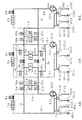
図5は定期検査時でプラント停止の状態であり、なお、ここでは例としてA系とC系により、非常用機器5a,5cと常・非常用機器7a、常用機器8d,8eを冷却する運転状態の場合を示す。
従って、このプラント停止時の運転状態では、A系とC系は共に冷却水ポンプ2a1 ,2a2 ,2c1 ,2c2 と、海水ポンプ15a1 ,15a2 ,15c1 ,15c2 、及び熱交換器4a1 ,4a2 ,4c1 ,4c2 を全台運転している。
【0044】
これには、A系隔離弁19a,22aとB系隔離弁19b,22bを閉止することにより、A系、B系、C系が分離される。
また、A系とC系については、非常用機器出口弁6a,6cとA系モード弁18a,21a、常用モード弁20,23及びC系第1隔離弁27aとC系第2隔離弁29aを開けることにより、A系では非常用機器5aと常・非常用機器7aが、C系では非常用機器5cと常用機器7d,7eに対する冷却が行われる。
【0045】
なお、C系においては、前記非常用機器出口弁6cと常用系モード弁20,23を開けた場合で、C系第1隔離弁27bとC系第2隔離弁29aを開けて、C系第1隔離弁27aとC系第2隔離弁29aを閉止した場合や、C系第1隔離弁27a,27bとC系第2隔離弁29a,29bの両方を開けた場合でも、上記と同様の機能が得られる。
【0046】
また、この時にB系においては、冷却運転中のA系及びC系から隔離されて停止状態となるので、各構成機器である非常用機器5bと常・非常用機器7b、及び冷却水ポンプ2b1 ,2b2 と海水ポンプ15b1 ,15b2 、さらに熱交換器4b1 ,4b2 や、非常用機器出口弁6b及びB系モード弁18b,21b等の保守点検を行うことができる。
【0047】
さらに、上記したB系の停止状態のほかにA系とC系についても、適宜各種弁を運用することにより、他の系統から隔離すると共に停止状態にして、それぞれの系統の各構成機器に対する保守点検を行うことができる。
【0048】
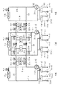
図6は原子力プラント事故時の運転状態で、A系とB系により非常用機器5a,5b及び常・非常用機器7a,7bを、C系で非常用機器5cを冷却する運転状態の場合を示す。
従って、このプラント事故時の運転状態では、A系乃至C系は共に冷却水ポンプ2a1 ,2a2 〜2c1 ,2c2 と、海水ポンプ15a1 ,15a2 〜15c1 ,15c2 、及び熱交換器4a1 ,4a2 〜4c1 ,4c2 を全台運転としている。
【0049】
これには、A系隔離弁19a,22aと、B系隔離弁18b,21bを閉止することにより、A系、B系、C系が分離される。
さらに、A系、B系については非常用機器出口弁6a,6bを開けることにより、A系では非常用機器5aと常・非常用機器7aの冷却を行い、B系では非常用機器5bと常・非常用機器7bの冷却が行われる。
【0050】
また、C系については、非常用機器出口弁6cを開け、C系第1隔離弁27a,29aとC系第2隔離弁27b,29bを閉止することにより、非常用機器5cの冷却を行うと共に常用機器8d,8eを隔離する。
【0051】
上記した各運転状態に示すように、各冷却負荷の非常用機器5a〜5cと常・非常用機器7a,7b及び常用機器8d,8eについて、2区分に分割する系統構成になることから、補機冷却装置を構成する各種機器の仕様を決定する上で、3系統の容量を均等に分配することが可能となり、このために、合理的な系統構成をすることができる。
【0052】
また、本発明における系統構成では、通常運転中において3系統の内の2系統を運転し、1系統を停止状態として隔離することができるために、各種機器を含めた系統の休止及び待機状態を保有することにより信頼性が向上する。
【0053】
【発明の効果】
以上本発明によれば、通常運転中においては常・非常用負荷を3系統の内任意の2系統で冷却し、常用負荷を2区分に分割して任意の2系統で冷却するので、設計時において補機冷却装置の構成機器について合理的な仕様を定めることができる。
また、3系統の内で1系統を停止状態とすることから、各種機器を含めた系統の休止及び待機状態を保有するので、保守性も優れて信頼性が向上する。
【図面の簡単な説明】
【図1】本発明に係る一実施の形態の原子力発電所の補機冷却装置の系統構成図。
【図2】本発明に係る一実施の形態で、第1の通常運転モード系統模式図。
【図3】本発明に係る一実施の形態で、第2の通常運転モード系統模式図。
【図4】本発明に係る一実施の形態で、第3の通常運転モード系統模式図。
【図5】本発明に係る一実施の形態で、検査時運転モード系統模式図。
【図6】本発明に係る一実施の形態で、事故時運転モード系統模式図。
【図7】従来の原子力発電所の補機冷却装置の系統構成図。
【符号の説明】
1a〜1c…冷却水供給配管、2a1 ,2a2 〜2c1 ,2c2 …冷却水ポンプ、3a〜3c…冷却水戻り配管、4a1 ,4a2 〜4c1 ,4c2 …熱交換器、5a〜5c…非常用機器、6a〜6c…非常用機器出口弁、7a,7b…常・非常用機器、8a〜8c…常用機器、9a〜9c,10a〜10c…常用機器隔離弁、11a〜11c…供給タイライン元弁、12a〜12c…戻りタイライン元弁、13…冷却水供給タイライン、14…冷却水戻りタイライン、15a1 ,15a2 〜15c1 ,15c2…海水ポンプ、16a1 ,16a2 〜16c1 ,16c2 …冷却海水供給配管、17a1 ,17a2 〜17c1 ,17c2 …放水配管、18a,21a…A系モード弁、18b,21b…B系モード弁、19a,22a…A系隔離弁、19b,22b…B系隔離弁、20,23…常用系モード弁、24a,24b…常・非常用ライン、25a,25b…常用ライン、26…常用供給ライン、27a,27b…C系第1隔離弁、28…常用戻りライン、29a,29b…C系第2隔離弁。[0001]
BACKGROUND OF THE INVENTION
The present invention relates to the heat generated by emergency equipment and normal / emergency equipment installed in a nuclear power plant and normal equipment required for normal operation, and is used as the final waste heat location in the sea, river, lake or atmosphere. It is related with the auxiliary machine cooling device of the nuclear power station for making it discharge | emit to etc.
[0002]
[Prior art]
Auxiliary equipment cooling systems in nuclear power plants consist of an auxiliary equipment cooling water system for freshwater loops and an auxiliary equipment cooling seawater system for seawater systems. Emergency equipment and ordinary / emergency equipment installed at nuclear power stations In addition, it is installed to release heat generated by regular equipment necessary for normal operation of nuclear power plants to the sea or the like, which is the final waste heat location.
[0003]
Therefore, this auxiliary machine cooling device is a closed loop comprising a heat exchanger and a cooling water supply pipe, a cooling water return pipe for returning the heat exchanged cooling water to the heat exchanger, and a cooling water pump provided in the cooling water return pipe. A seawater system consisting of a freshwater auxiliary cooling water system and a water discharge pipe for connecting the seawater pump and cooling seawater supply piping for supplying cooling seawater to the heat exchanger and returning the heat exchanged cooling seawater to the sea, for example. The system composed of the auxiliary cooling seawater system is composed of 3 systems.
[0004]
As for this auxiliary machine cooling device, as shown in the system configuration diagram of FIG. 7, the three systems A, C, and B from the left have almost the same configuration, and the cooling water supply in which the cooling water of the auxiliary machine cooling water system circulates. The cooling water return pipes 3a to 3c in which the pipes 1a to 1c and the duplex cooling water pumps 2a 1 , 2a 2 to 2c 1 and 2c 2 are connected in series are duplexed heat exchangers 4a 1 and 4a 2 to 4c 1 and 4c 2 are connected.
[0005]
Between the cooling water supply pipes 1a to 1c and the cooling water return pipes 3a to 3c, emergency equipment outlet valves 6a to 6c are connected in series with the emergency equipment 5a to 5c which are loads to be cooled, and A and C are connected between the two systems of cooling
[0006]
Further, between the cooling water supply pipes 1a to 1c and the cooling water return pipes 3a to 3c, common devices 8a to 8c are connected to both sides via common device isolation valves 9a to 9c and 10a to 10c.
Further, both ends of the regular devices 8a to 8c are connected to a cooling water
[0007]
Incidentally, the exhaust heat location for example the sea, for the auxiliary cooling seawater system of seawater system, to the heat exchanger 4a 1, 4a 2 ~4c 1, 4c 2 are
[0008]
As described above, the auxiliary equipment cooling device constituted by three systems has a heat removal capability of 50% in each of the systems A to C as the heat removal performance of the emergency equipment 5a to 5c by design at the time of an accident. doing.
In other words, it is a redundant design that satisfies the required heat removal capacity in two of the three systems, so that even if one system fails due to some event, the remaining two systems will satisfy the cooling function. The basic concept of safety design in nuclear power plants follows the single failure criteria.
[0009]
In the auxiliary machine cooling apparatus configured as described above, the cooling water circulating through the cooling water supply pipes 1a to 1c and the cooling water return pipes 2a to 2c by the cooling water pumps 2a 1 , 2a 2 to 2c 1 and 2c 2 The emergency equipments 5a to 5c that are cooled by the heat exchangers 4a 1 , 4a 2 to 4c 1 , 4c 2 and are the cooling target loads through the cooling water supply pipes 1a to 1c, and the normal /
[0010]
The cooling water whose temperature has been increased by cooling the loads to be cooled is returned to the heat exchangers 4a 1 , 2a 1 , 2c 2 , 2c 2 through the cooling water return pipes 3a to 3c and the cooling water pumps 2a 1 , 2a 2 to 2c 1 , 2c 2 , respectively. 4a 2 to 4c 1 and 4c 2 are returned.
In the heat exchangers 4a 1 , 4a 2 to 4c 1 , 4c 2 , the cooled cooling water is cooled by the sea water pumps 15a 1 ,
[0011]
In this auxiliary cooling seawater equipment, during normal operation the seawater pump one in each channel co (e.g. 15a 1, 15b 1, 15c 1) and the
In addition, in the event of an accident, all the systems are equipped with two seawater pumps (15a 1 ,
[0012]
At the time of periodic inspection of the nuclear power plant, one of the three auxiliary cooling systems is stopped and the cooling water pumps 2a 1 , 2a 2 to 2c 1 , 2c 2 , seawater pumps 15a 1 , 15a are stopped. 2 ~15c 1, 15c 2, heat exchanger 4a 1, 4a 2 ~4c 1, to implement the maintenance of 4c 2 or the like.
[0013]
At this time as well, the cooling of the normal devices 8a to 8c and the normal /
Therefore, during the periodic inspection of the nuclear power plant, the two operating systems are all operated with two pumps and two heat exchangers.
[0014]
[Problems to be solved by the invention]
In the above-described conventional auxiliary machine cooling device, the emergency equipment 5a to 5c, the normal /
[0015]
However, the normal and
Therefore, the cooling water pumps 2a 1 , 2a 2 to 2c 1 , 2c 2 , the seawater pumps 15a 1 ,
[0016]
For this reason, even when the tie line operation is performed through the cooling water
Furthermore, the auxiliary machine cooling device includes two cooling water pumps 2a 1 , 2a 2 to 2c 1 , 2c 2 , two seawater pumps 15a 1 ,
[0017]
However, all units in each system are operated only during an accident and when the reactor is shut down. During normal operation, one cooling water pump (for example, 2a 1 , 2b 1 , 2c 1 ) and one unit of seawater are used. Only pumps (for example, 15a 1 , 15b 1 , 15c 1 ) and one heat exchanger (for example, 4a 1 , 4b 1 , 4c 1 ) are operated.
[0018]
Therefore, the remaining one cooling water pump (for example, 2a 2 , 2b 2 , 2c 2 ), one seawater pump (for example, 15a 2 , 15b 2 , 15c 2 ), one heat exchanger (for example, 4a 2 , 4b 2 , 4c 2 ) are in a standby state. For this reason, the system could not be stopped during normal operation for any system.
[0019]
The purpose of the present invention is to divide the cooling system into three systems according to the safety separation division of the nuclear power plant, and divide the normal / emergency equipment and the regular equipment into two systems for normal operation, periodic inspection and accidents. It is an object of the present invention to provide an auxiliary equipment cooling device for a nuclear power plant that performs cooling by two to three systems in accordance with the operation mode.
[0020]
[Means for Solving the Problems]
In order to achieve the above object, the auxiliary equipment cooling device for a nuclear power plant according to the invention described in
[0021]
During normal operation and periodic inspections by operating various valves, two of the three systems are operated, cooling water is supplied to the normal / emergency equipment and normal equipment of each system, and cooling is performed. Can wait or maintain. In the event of an accident, the three systems are operated together to supply cooling water to emergency equipment and normal / emergency equipment.
[0022]
An auxiliary equipment cooling device for a nuclear power plant according to a second aspect of the present invention is the nuclear power plant auxiliary device cooling apparatus according to the first aspect, wherein a plurality of normal / emergency devices and normal devices connected in parallel to the cooling water supply tie line and the cooling water return tie line Among them, the normal / emergency equipment is provided in one system on the parallel pipes provided at the two ends of the tie line, and the parallel pipes provided at the two ends and the cooling water supply. Connection between the connection point of the tie line and the parallel pipe provided with the regular equipment and the connection point of the cooling water supply tie line and the connection of the parallel pipe provided at the two ends and the cooling water return tie line A normal / emergency device isolation valve is provided between the point and a parallel pipe provided with the normal device and a connection point of the cooling water return tie line so that the normal / emergency device can be isolated. .
[0023]
The normal / emergency equipment is divided into two systems for the three cooling systems. During normal operation, two systems are used by operating the mode valve provided in the cooling water supply pipe connected to each normal / emergency equipment. Cooling is performed by supplying cooling water from normal to emergency equipment.
In the event of an accident, cooling is performed by supplying cooling water from two specific systems by operating isolation valves.
[0024]
An auxiliary equipment cooling device for a nuclear power plant according to the invention described in
[0025]
Since the regular equipment is divided into two systems for the three cooling systems, the cooling water is supplied from the two systems to the regular equipment by operating the mode valve provided in the cooling water supply pipe connected to each regular equipment. Cool down.
In the event of an accident, cooling is performed by supplying cooling water from two specific systems by operating isolation valves.
[0026]
DETAILED DESCRIPTION OF THE INVENTION
An embodiment of the present invention will be described with reference to the drawings. In addition, about the same component as the above-mentioned prior art, the same code | symbol is attached | subjected and detailed description is abbreviate | omitted.
As shown in the system configuration diagram of FIG. 1, the auxiliary equipment cooling device of the nuclear power plant is A system (first system), C system (third system), and B system (second system) from the left. Cooling water comprising three systems, cooling water supply pipes 1a to 1c in which cooling water by fresh water of the auxiliary cooling water system circulates, and duplex cooling water pumps 2a 1 , 2a 2 to 2c 1 , 2c 2 in series The return pipes 3a to 3c are connected to the duplex heat exchangers 4a 1 , 4a 2 to 4c 1 , 4c 2 .
[0027]
Between the cooling water supply pipes 1a to 1c and the cooling water return pipes 3a to 3c, emergency equipments 5a to 5c that are loads to be cooled and emergency equipment outlet valves 6a to 6c are connected in series, Each of them forms a closed loop as a whole.
Further, a cooling water
[0028]
In the cooling water
As for the cooling water
[0029]
Further, between the cooling water
Further, the normal /
[0030]
Between the cooling water
[0031]
A C system
[0032]
Furthermore, the waste heat location for example the sea, for the auxiliary cooling seawater system of seawater system, to the heat exchanger 4a 1, 4a 2 ~4c 1, 4c 2 are
[0033]
Next, the effect | action by the said structure is demonstrated. The operation modes of the accessory cooling device in each operation state of the nuclear power plant are shown in the operation mode system schematic diagrams of FIGS. 2 to 6, and the flow of the cooling water at this time is indicated by a bold line.
FIG. 2 shows the first normal operation state, in which the normal and
Therefore, in both the A system and the B system, the cooling water pumps 2a 1 , 2a 2 , 2b 1 , 2b 2 , the seawater pumps 15a 1 , 15a 2 , 15b 1 , 15b 2 and the heat exchangers 4a 1 , 4a 2 , 4b 1 , Although all 4b 2 are operated, the C-system cooling water pumps 2c 1 and 2c 2 , the seawater pumps 15c 1 and 15c 2 , and the heat exchangers 4c 1 and 4c 1 are all stopped.
[0034]
For this purpose, the C system
[0035]
Further, by closing the normal
Note that all of the C-system cooling water pumps 2c 1 and 2c 2 , the seawater pumps 15c 1 and 15c 2 , and the heat exchangers 4c 1 and 4c 1 are in a stop standby state.
[0036]
FIG. 3 shows the second normal operation state, in which the normal /
Therefore, in both the B system and the C system, the cooling water pumps 2b 1 , 2b 2 , 2c 1 , 2c 2 , the seawater pumps 15b 1 , 15b 2 , 15c 1 , 15c 2 and the heat exchangers 4b 1 , 4b 2 , 4c 1 , Although all the units 4c 2 are operated, the A-system cooling water pumps 2a 1 and 2a 2 and the seawater pumps 15a 1 and 15a 2 and the heat exchangers 4a 1 and 4a 1 are all stopped.
[0037]
For this purpose, the A system mode valves 18a and 21a are closed to isolate the A system from the B and C systems, and the emergency equipment outlet valves 6a to 6c are closed to disconnect the emergency equipment 5a to 5c.
[0038]
Further, by closing the normal
Note that all of the A-system cooling water pumps 2a 1 and 2a 2 , the seawater pumps 15a 1 and 15a 2 , and the heat exchangers 4a 1 and 4a 1 are in a stop standby state.
[0039]
FIG. 4 shows a third normal operation state, in which the normal /
Therefore, in both the A system and the C system, the cooling water pumps 2a 1 , 2a 2 , 2c 1 , 2c 2 , the seawater pumps 15a 1 , 15a 2 , 15c 1 , 15c 2 and the heat exchangers 4a 1 , 4a 2 , 4c 1 , Although all the units 4c 2 are operated, the B-system cooling water pumps 2a 1 and 2a 2 and the seawater pumps 15a 1 and 15a 2 and the heat exchangers 4a 1 and 4a 1 are all stopped.
[0040]
For this purpose, the A
Also, by closing the
[0041]
Note that all of the B-system cooling water pumps 2b 1 and 2b 2 , the seawater pumps 15b 1 and 15b 2 , and the heat exchangers 4b 1 and 4b 1 are in a stop standby state.
As a result, in the first to third normal operation states described above, since the C system, the A system, and the B system are in the stop standby state, the maintenance and inspection for each component device in the stop standby system is performed. It is possible to implement.
[0042]
Although not shown, in the present embodiment, the normal /
[0043]
FIG. 5 shows a state where the plant is stopped at the time of periodic inspection. Here, as an example, an operation for cooling the emergency equipment 5a, 5c, the emergency /
Therefore, in the operating condition at the time of plant shutdown, A system and C system along with the cooling water pump 2a 1, 2a 2, 2c 1 ,
[0044]
For this purpose, the A system, B system, and C system are separated by closing the A system isolation valves 19a, 22a and the B
For the A system and the C system, the emergency equipment outlet valves 6a and 6c, the A system mode valves 18a and 21a, the
[0045]
In the C system, when the emergency equipment outlet valve 6c and the normal
[0046]
Also, at this time, the B system is isolated from the A system and the C system during the cooling operation and is in a stopped state. Therefore, the emergency equipment 5b, the normal /
[0047]
Furthermore, in addition to the above-mentioned B system stop state, the A system and the C system are also maintained in the stop state by isolating them from other systems by appropriately operating various valves, and maintaining each component of each system. Inspection can be performed.
[0048]
FIG. 6 shows the operation state at the time of an accident at the nuclear power plant, in which the emergency equipment 5a, 5b and the emergency /
Therefore, in the operating state at the time of the plant accident, the A system to the C system are both the cooling water pumps 2a 1 , 2a 2 to 2c 1 , 2c 2 , the seawater pumps 15a 1 ,
[0049]
For this purpose, the A system, B system, and C system are separated by closing the A system isolation valves 19a and 22a and the B
Further, for the A system and the B system, the emergency equipment outlet valves 6a and 6b are opened to cool the emergency equipment 5a and the emergency /
[0050]
For the C system, the emergency equipment 5c is cooled by opening the emergency equipment outlet valve 6c and closing the C system first isolation valves 27a and 29a and the C system
[0051]
As shown in each operation state described above, the emergency equipment 5a to 5c, the emergency /
[0052]
Also, in the system configuration in the present invention, two of the three systems can be operated during normal operation, and one system can be isolated as a stopped state. Holding it improves reliability.
[0053]
【The invention's effect】
As described above, according to the present invention, during normal operation, the normal / emergency load is cooled by any two of the three systems, and the normal load is divided into two sections and cooled by any two systems. Therefore, reasonable specifications can be established for the components of the auxiliary cooling device.
In addition, since one of the three systems is in a stopped state, the system including the rest and standby states including various devices are retained, so that maintainability is excellent and reliability is improved.
[Brief description of the drawings]
FIG. 1 is a system configuration diagram of an auxiliary machine cooling device for a nuclear power plant according to an embodiment of the present invention.
FIG. 2 is a schematic diagram of a first normal operation mode system in an embodiment according to the present invention.
FIG. 3 is a schematic diagram of a second normal operation mode system in the embodiment according to the present invention.
FIG. 4 is a schematic diagram of a third normal operation mode system in the embodiment according to the present invention.
FIG. 5 is a schematic diagram of an inspection operation mode system in an embodiment according to the present invention.
FIG. 6 is a schematic diagram of an operation mode system at the time of an accident in one embodiment according to the present invention.
FIG. 7 is a system configuration diagram of a conventional auxiliary equipment cooling device for a nuclear power plant.
[Explanation of symbols]
1a to 1c: cooling water supply pipe, 2a 1 , 2a 2 to 2c 1 , 2c 2 ... cooling water pump, 3a to 3c ... cooling water return pipe, 4a 1 , 4a 2 to 4c 1 , 4c 2 ... heat exchanger, 5a to 5c ... emergency equipment, 6a to 6c ... emergency equipment outlet valve, 7a, 7b ... normal / emergency equipment, 8a-8c ... usual equipment, 9a-9c, 10a-10c ... usual equipment isolation valve, 11a- 11c ... supply tie-line base valve, 12 a to 12 c ... returning tie line base valve, 13 ... cooling water supply tie-line, 14 ... cooling water return tie line, 15a 1, 15a 2 ~15c 1 ,
Claims (3)
Priority Applications (1)
| Application Number | Priority Date | Filing Date | Title |
|---|---|---|---|
| JP29660198A JP3607096B2 (en) | 1998-10-19 | 1998-10-19 | Auxiliary cooling system for nuclear power plant |
Applications Claiming Priority (1)
| Application Number | Priority Date | Filing Date | Title |
|---|---|---|---|
| JP29660198A JP3607096B2 (en) | 1998-10-19 | 1998-10-19 | Auxiliary cooling system for nuclear power plant |
Publications (2)
| Publication Number | Publication Date |
|---|---|
| JP2000121784A JP2000121784A (en) | 2000-04-28 |
| JP3607096B2 true JP3607096B2 (en) | 2005-01-05 |
Family
ID=17835670
Family Applications (1)
| Application Number | Title | Priority Date | Filing Date |
|---|---|---|---|
| JP29660198A Expired - Fee Related JP3607096B2 (en) | 1998-10-19 | 1998-10-19 | Auxiliary cooling system for nuclear power plant |
Country Status (1)
| Country | Link |
|---|---|
| JP (1) | JP3607096B2 (en) |
-
1998
- 1998-10-19 JP JP29660198A patent/JP3607096B2/en not_active Expired - Fee Related
Also Published As
| Publication number | Publication date |
|---|---|
| JP2000121784A (en) | 2000-04-28 |
Similar Documents
| Publication | Publication Date | Title |
|---|---|---|
| JP6420040B2 (en) | Emergency transformer cooling system and emergency transformer cooling method for underground substation | |
| US9312035B2 (en) | Semi-portable emergency cooling system for removing decay heat from a nuclear reactor | |
| CN113783361B (en) | Cooling system | |
| US20160248273A1 (en) | Data center power distribution | |
| JP3607096B2 (en) | Auxiliary cooling system for nuclear power plant | |
| CN113104191A (en) | Marine generator set seawater cooling system | |
| CN212032665U (en) | Nuclear power cooling system and nuclear power system | |
| JP6373706B2 (en) | Air conditioning system | |
| CN115985535A (en) | Cooling water system of multi-module high temperature gas-cooled reactor nuclear island equipment | |
| JP2001074874A (en) | Reactor cooling equipment | |
| JP2020068152A (en) | Fuel cell device | |
| JP2568929B2 (en) | Engine power supply system for multiple demand facilities | |
| JP3286129B2 (en) | Maintenance inspection method for auxiliary cooling equipment of nuclear power plants | |
| JPH11160481A (en) | Emergency auxiliary equipment cooling equipment for nuclear power plants | |
| CN208706816U (en) | Battery cooling circuits, vehicles, battery storage and charging stations | |
| JP2001183492A (en) | Cooling seawater facilities for nuclear power plants | |
| CN116110622A (en) | Nuclear power plant equipment cooling water system | |
| CN110972448B (en) | Heat exchange system | |
| JPS62119499A (en) | Auxiliary cooling device | |
| CN119773477A (en) | A water cooling system for unmanned transport vehicles | |
| JP2525801B2 (en) | Auxiliary equipment cooling system cooling device | |
| JPH0659074A (en) | Cooling system of heat exchanger for auxiliary machinery | |
| CN118744791A (en) | A redundancy design method and system for a fresh water system of an LNG electric propulsion ship | |
| CN121001317A (en) | Refrigerant flow control method and refrigerant distribution system | |
| JP2023141107A (en) | air conditioning system |
Legal Events
| Date | Code | Title | Description |
|---|---|---|---|
| A711 | Notification of change in applicant |
Free format text: JAPANESE INTERMEDIATE CODE: A712 Effective date: 20040319 |
|
| A977 | Report on retrieval |
Free format text: JAPANESE INTERMEDIATE CODE: A971007 Effective date: 20040617 |
|
| A131 | Notification of reasons for refusal |
Free format text: JAPANESE INTERMEDIATE CODE: A131 Effective date: 20040622 |
|
| A521 | Written amendment |
Free format text: JAPANESE INTERMEDIATE CODE: A523 Effective date: 20040820 |
|
| TRDD | Decision of grant or rejection written | ||
| A01 | Written decision to grant a patent or to grant a registration (utility model) |
Free format text: JAPANESE INTERMEDIATE CODE: A01 Effective date: 20041005 |
|
| A61 | First payment of annual fees (during grant procedure) |
Free format text: JAPANESE INTERMEDIATE CODE: A61 Effective date: 20041006 |
|
| R150 | Certificate of patent or registration of utility model |
Free format text: JAPANESE INTERMEDIATE CODE: R150 |
|
| FPAY | Renewal fee payment (event date is renewal date of database) |
Free format text: PAYMENT UNTIL: 20081015 Year of fee payment: 4 |
|
| FPAY | Renewal fee payment (event date is renewal date of database) |
Free format text: PAYMENT UNTIL: 20081015 Year of fee payment: 4 |
|
| FPAY | Renewal fee payment (event date is renewal date of database) |
Free format text: PAYMENT UNTIL: 20091015 Year of fee payment: 5 |
|
| FPAY | Renewal fee payment (event date is renewal date of database) |
Free format text: PAYMENT UNTIL: 20101015 Year of fee payment: 6 |
|
| FPAY | Renewal fee payment (event date is renewal date of database) |
Free format text: PAYMENT UNTIL: 20111015 Year of fee payment: 7 |
|
| FPAY | Renewal fee payment (event date is renewal date of database) |
Free format text: PAYMENT UNTIL: 20111015 Year of fee payment: 7 |
|
| S531 | Written request for registration of change of domicile |
Free format text: JAPANESE INTERMEDIATE CODE: R313531 |
|
| FPAY | Renewal fee payment (event date is renewal date of database) |
Free format text: PAYMENT UNTIL: 20111015 Year of fee payment: 7 |
|
| R350 | Written notification of registration of transfer |
Free format text: JAPANESE INTERMEDIATE CODE: R350 |
|
| LAPS | Cancellation because of no payment of annual fees |