JP3607079B2 - Slide control device for vehicle sliding door - Google Patents
Slide control device for vehicle sliding door Download PDFInfo
- Publication number
- JP3607079B2 JP3607079B2 JP15552098A JP15552098A JP3607079B2 JP 3607079 B2 JP3607079 B2 JP 3607079B2 JP 15552098 A JP15552098 A JP 15552098A JP 15552098 A JP15552098 A JP 15552098A JP 3607079 B2 JP3607079 B2 JP 3607079B2
- Authority
- JP
- Japan
- Prior art keywords
- duty
- control
- motor
- slide
- predetermined
- Prior art date
- Legal status (The legal status is an assumption and is not a legal conclusion. Google has not performed a legal analysis and makes no representation as to the accuracy of the status listed.)
- Expired - Fee Related
Links
Images
Landscapes
- Power-Operated Mechanisms For Wings (AREA)
Description
【0001】
【発明の属する技術分野】
本発明は、車両用スライドドアのスライド制御装置に関するものである。
【0002】
【従来の技術】
従来、車両としての例えば自動車に設けられたスライドドアにおいて、モータによりスライドさせてドアの自動開閉を可能にしたものがある。そのような自動スライドドアのスライド制御にあっては、スライド速度を一定にしてスライドドアの開閉を行うことが考えられ、そのためには例えばモータをデューティ制御すると良い。そのようなデューティ制御の制御幅としては、車両が傾斜(後席閉扉時あっては上向き)して停車している場合を想定して設定する必要があり、許容最大傾斜状態においても一定のスライド速度を得られるように設定していた。
【0003】
【発明が解決しようとする課題】
しかしながら、例えばデューティ制御においてモータ回転パルスを検出し、そのパルス周期の長短変化に応じてデューティを増減させて、モータ速度が一定になるように制御することが考えられるが、閉扉時に何らかの挟み込みを生じた場合には上記パルス周期が長くなるため、デューティをより一層上げる制御を行うことになる。そのため、挟み込み処理を行うまでに、過大な荷重が生じてしまうという問題があった。
【0004】
【課題を解決するための手段】
このような課題を解決して、定速度制御において過大な荷重が生じることなく挟み込み検出を行うことを実現するために、本発明に於いては、車両にスライド自在に設けられたスライドドアに連結されたワイヤを巻き掛けられたプーリを駆動するためのモータと、前記車両の停車時の傾斜状態にかかわらず前記スライドドアを所定速度で開閉するべく前記モータをデューティ制御するモータ制御装置とを有する車両用スライドドアのスライド制御装置であって、前記モータ制御装置が、前記スライドドアを全開位置から閉じる向きにスライドさせる際に水平停車状態において所定の定速度でスライドさせる所定の基準デューティ制御により当該全開位置近傍における所定量をスライドするのに要した所定のパラメータの実測値を検出し、前記基準デューティ制御による前記所定量に要する前記パラメータの基準値に対する前記実測値の大小に応じて前記基準デューティ制御に対してデューティを増減させて、前記傾斜状態によらず常に所定の定速度となるように前記増減されたデューティを用いて前記所定量のスライド以後における前記モータのデューティ制御を行うものとした。
【0005】
このようにすることにより、全開状態からの閉扉時にその全開位置近傍の所定量として例えば所定の区間を移動させる間の所定のパラメータとして例えばスライド時間を見ることにより、その実スライド時間と基準スライド時間とを比較して、実スライド時間の方が長い場合には、何らかの負荷がある場合であり、また全開位置近傍における移動時であることから挟み込みではなく、停車時の車両の傾斜状態であると判断でき、基準値との差が傾斜による負荷分によるものであるとして、その負荷分に対応してデューティを増減させて、モータのデューティ制御における無駄な駆動力を発生させることなく、常に所定の速度でスライド動作させることができる。また、上記所定区間を定速度制御する場合には、パラメータとして、駆動出力値(例えばPWM制御における駆動出力パルス数)を見たり、駆動制御・制動(駆動によるオーバシュートを抑えるため)制御の比率を見ることができる。あるいは、所定量としては所定の時間であっても良く、その場合にはその所定の時間に要したモータの回転数が負荷の違いで変化することをもって、上記と同様に処理できる。
【0006】
【発明の実施の形態】
以下に添付の図面に示された具体例に基づいて本発明の実施の形態について詳細に説明する。
【0007】
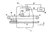
図1は、本発明が適用された車両用スライドドアのスライド制御装置の概略構成を示す全体図である。図1において、図示されない車両の後席への乗降用として車両前後方向にスライド自在なスライドドア1が設けられている。スライドドア1は、その上下端の一部を図示されないドアサッシに設けられているレールによりガイドかつ支持されていると共に、車両前後方向に延在するように設けられたガイドレール2にスライド自在に支持されたスライダ3を介して車両後方側の一部が支持されている。そのスライダ3は、ガイドレール2の両端部近傍に配設された両プーリ4間に巻き掛けられたワイヤ5に結合されている。
【0008】
ワイヤ5の両端は駆動ユニット6のケーシング内に設けられた駆動ドラム6aに互いに逆方向に巻回され、同じく駆動ユニット6のケーシング内に設けられたモータ7により駆動ドラム6aが回転駆動されるようになっており、モータ7の正逆転に応じて駆動ドラム6aも正逆転するため、ワイヤ5が往復動するようになっている。それにより、スライダ3がガイドレール2にガイドされつつ車両前後(図における左右)方向に往復動して、スライドドア1がスライドによる開閉動作を行い得る。
【0009】
また、モータ7の駆動を制御するためのモータ制御装置8が設けられており、そのモータ制御装置8にはモータ7の回転パルス信号Pが入力し、モータ制御装置8からはモータ7に正逆転駆動信号Dが出力されるようになっている。そして、モータ制御装置8では、デューティ制御によりモータ7を定速度で駆動する。
【0010】
図1ではスライドドア1の全開状態が示されており、その状態から閉扉動作を行わせる際にはスライドドア1を図の矢印Aに示される向きに移動させることになり、その閉扉時における本発明に基づく制御を以下に示す。
【0011】
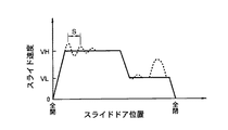
まず、本発明が適用された車両用スライドドアのスライド制御にあっては、図2に示されるように、全開位置から比較的高速VH(例えば240mm/sec)で移動させ、全閉手前の所定の位置から比較的低速VL(例えば100mm/sec)で移動させるようにしており、それら各定速制御をPWM制御により行う。なお、高速VH制御から低速VL制御への切り替え位置は、回転パルス信号Pのカウント数で判断でき、実車では全閉位置手前100mm程度であり、図における高速制御と低速制御との区間の比は実際のものとは異なる。
【0012】
また、図2にあっては、モータ7の駆動信号Dによるスライドドア1の制御速度の変化を実線で示し、その制御値による実際のスライド速度の変化を波線で示している。図の波線に示されるように、実際のスライド速度は、スライドドア1の摺接部分の摩擦抵抗などによりある程度変化する。
【0013】
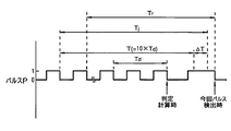
次に、本スライド制御における挟み込み判定について図3を参照して以下に示す。本制御における挟み込み判定時のタイミングは、モータ7の回転パルス信号の検出時(例えばパルス立ち下がり時)である。例えばモータ7の1回転(例えば20パルス)に要する周期を1パルス入力毎に算出し、その周期の変化を監視する。本実施の形態では、上記モータ7の1回転に要する周期を、判定時の前2パルス分の周期を基準周期Tdとして算出し、その基準周期Tdを10倍してモータ7の1回転周期に相当する20パルス分を算出して、判定の基準となる換算1回転周期Tとしている。
【0014】
前回の挟み込み判定時に上記したようにして求めた換算1回転周期Tに許容偏差ΔT分を加算して判定値Tj(=T+ΔT)とし、今回の挟み込み判定時に求めた1回転(20パルス分)の実周期Trとを比較して、Tr>Tjの状態であったら挟み込み判定とし、その挟み込み判定が3回連続したら実際に挟み込み状態になったと判定する。なお、上記許容偏差ΔTは、予め所定値を定めておくのではなく、換算1回転周期Tに基づき、判定計算時毎に算出する。
【0015】
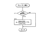
次に、モータのPWMデューティ制御を行う際のデューティの求め方を図4を参照して示す。図4の第1ステップST1では実スライド時間から算出するモータ7の1回転周期であって良い負荷算出周期Tbの測定が終了したか否かを判別する。この負荷算出周期Tbの測定は、全開位置近傍の所定区間Sを通過するスライドドア1の走行時間から算出するようにしている。なお、この所定区間Sは、図2に示されるように全開位置から最初の定速度である高速VHに達した後であって、極力全開位置に近い所である。本実施の形態にあっては、所定量として所定区間Sを用い、パラメータとして走行(スライド)時間を適用するものである。
【0016】
ところで、自動車のスライドドア構造にあっては、一般的にスライドドア1の全開位置における停止状態を確保するべくガイドレール2の所定の位置に突状のチェッカー9が設けられているため、そのチェッカー9をスライダ3が乗り越えた後のガイドレール2の直線部分を測定区間としている。本実施の形態では、全閉位置でパルスカウント値を0として、開扉時にパルス数をカウントしていき、全開位置(例えば所定の全開相当カウント数)からチェッカーを乗り越えかつ上記定速度(高速VH)になったとして良い所定の助走カウント数経過後から測定開始し、所定の測定カウント数をカウントしたら測定終了としている。これによれば、別個に変位センサなどを設ける必要がなく、部品点数を少なくし得る。
【0017】
上記第1ステップST1で測定が終了していないと判別された場合には本ルーチンを終了し、次回の割り込み処理で再度第1ステップST1を実行する。第1ステップST1で負荷算出周期Tdの測定が終了したと判断された場合には第2ステップST2に進む。
【0018】
車両の停車状態は常に水平状態であるとは限らず、道路形状により車両前側が下向きあるいは上向きになる。したがって、車両前方に向けてスライドドア1を移動させて閉扉するものにあっては、車両前側が上向きの状態で停車している場合にはスライドドア1は全開側に自然にスライドしようとするため、閉扉時には傾斜による開扉方向の力が負荷として作用する。
【0019】
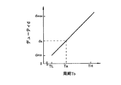
本発明では、第2ステップST2で、モータ7に対するデューティ制御におけるデューティdを例えば図5に示される関係式から算出する。図5には、スライド時の予め設定された定速度に対応する定速度周期Taと、その定速度を水平停車状態にいて確保し得る標準デューティdaとの両者の交点を通る直線が示されているが、これは、上記測定区間を標準デューティdaで駆動した場合における負荷(デューティd)と測定時間(周期Tb)との変化である。
【0020】
前下がりで停車している場合には負荷が軽くなり、それとは逆に前上がりで停車している場合には負荷が重くなることから、標準デューティdaで駆動した場合には上記測定区間をスライドする際の周期Tbが負荷の違いに応じて異なる。例えば、本制御対象の最低負荷時と最高負荷時とにおける各周期を図5において低負荷周期TLと高負荷周期THとして示す。そして、各場合における上記定速度でスライドさせるためのデューティdが、それぞれ低負荷デューティdminと高負荷デューティdmaxとして示されるようになる。
【0021】
低負荷周期TL及び低負荷デューティdminによる点と、高負荷周期TH及び高負荷デューティdmaxによる点とを結ぶ直線により、本制御におけるデューティdを求めることができ、そのデューティdの算出式は、
d=Tb・(dmax−dmin)/(TH−TL)…(1)
となる。第2ステップST2では、定速度制御を行い得るデューティdを上記式(1)を用いて求め、そのデューティdを用いて測定区間S以後におけるモータ7のデューティ制御を行う。
【0022】
このようにして、停車時の傾斜状態による負荷の大小に対応させて標準デューティdaに対する増減を考慮したデューティdをもって速度制御を行うことから、予め最大負荷に応じた過大な駆動力をもって全ての状況下でモータを駆動する必要がなく、スライドドア1を負荷に応じた好適な駆動力をもって常に所定の定速度にて自動的にスライドさせることができる。その駆動力の標準状態(水平停車時)に対する増減分は負荷の増減分と相殺されることになり、挟み込み時の荷重の程度は標準状態と何ら変わることがない。したがって、挟み込みを周期の増大で判断する制御において、挟み込み判断終了までの荷重の増大は、傾斜停車状態による負荷の大小に影響されることがなく、周期を基準とした挟み込み判断を好適に行い得る。
【0023】
なお、本発明によれば、基準となる区間のスライド時間(本実施の形態ではモータ1回転当たりの周期に換算している)の基準値に対する大小から負荷の大きさを推定している。したがって、本実施の形態で示した車両進行方向に対する傾斜に限定されるものではなく、季節の温度変化による摺動抵抗の変化など種々の外的要因による負荷の変動に対しても適用可能である。
【0024】
上記実施の形態では、所定区間を基準デューティ制御で走行させることによる実スライド時間と基準スライド時間との比較によりデューティを決定するようにしたが、本発明によればこれに限定されるものではない。
【0025】
例えばPWM制御における駆動(駆動出力パルス)回数を見ることができる。この場合には、上記所定区間Sを定速度(例えば200mm/sec)でスライドさせる定速度制御を行うようにし、その区間での駆動出力回数の基準値(水平停車状態における定速度制御)に対する違いにより負荷を推定する。なお、所定区間としては、チェッカー9を乗り越した後のそのチェッカー9のばね力の影響を受けなくなる位置から開始するようにする。また、パラメータは駆動出力回数となる。
【0026】
この場合には、定速度を維持するためには負荷に見合った駆動出力を発生させなければならず、それはPWM制御においては駆動出力回数に相当する。例えば閉扉方向に上向き停車の場合には駆動出力パルス数は増え、逆に下向きならば駆動出力パルス数は減ることになり、上記実施の形態と同様に処理できる。
【0027】
あるいは、パラメータとして、制動制御と駆動制御との比率を用いることができる。この場合にも上記所定区間Sに対して定速度制御を行って、定速度に維持するために行った制動制御の回数(制動出力パルス数)と駆動制御の回数(駆動制御パルス数)との比率を上記と同様に基準値と比較することにより負荷を推定する。
【0028】
すなわち、閉扉方向に下向き停車の場合にはドアの重力加速度が閉め方向に加わるため駆動より制動の比率が高く、逆に上向き停車の場合には重力加速度が開き方向に加わるため制動より駆動の比率が高くなる。
【0029】
この制動制御と駆動制御との比率から負荷を推定する別の形態としては、任意の区間の駆動出力デューティの総和と、駆動出力デューティの総和/制動出力デューティの総和との比を見ても良い。この場合には、初期の速い目標速度(例えば250mm/sec)に達するまでに徐々に出力デューティを上げていき、安定した一定速度になったとみなされた時のデューティをもって、負荷に見合ったオフセットのデューティとする。これは、制動も同様に考えることで、直接デューティとなる。
【0030】
あるいは、所定量をスライド時間として、パラメータを駆動パルスのカウント数としても良い。この場合には、例えば上記実施の形態と同様にチェッカー9を乗り越えた後の所定の開始位置(例えばパルスカウント数で設定可)から開始する所定のスライド測定時間を定めておき、そのスライド測定時間内を基準デューティ制御により駆動した際の駆動出力パルスの実カウント数と、水平停車状態でのスライド測定時間内における基準デューティ制御による基準カウント数とを比較する。
すなわち、同じ基準デューティ駆動では、上り坂閉扉時には負荷の増大によりスライド速度が遅くなって実カウント数が少なくなり、下り坂閉扉時には逆にスライド速度が速くなって実カウント数が多くなる。そのようにして基準カウント数に対する実カウント数の変化に基づいて、それ以降のデューティを決定する。
【0031】
【発明の効果】
このように本発明によれば、全開状態からの閉扉時における全開位置近傍の所定量としての所定区間を移動させる際の時間や駆動出力値や制動/駆動制御比率、あるいは所定量としての所定時間を移動させる際の駆動(出力パルス)回数をパラメータとして、各基準値に対する実測値の変化により停車時の傾斜などによる負荷の違いを判別して、水平停車時の基準デューティに対して負荷の違いに応じて増減させたデューティをもってそれ以降のモータのデューティ制御を行うことから、予め最大負荷に対応させたデューティ制御を行うことによる過大な駆動力を発生させてしまうことなく、常に好適な駆動力をもって所定の定速度でドアのスライド自動動作を行わせることができるため、閉扉時の挟み込みをスライド速度の変化により判断する制御において無用に過大な荷重が生じてしまうなどの問題が生じることを防止し得る。
【図面の簡単な説明】
【図1】本発明が適用された車両用スライドドアのスライド制御装置の概略構成を示す全体図。
【図2】本発明が適用されたスライドドアの速度制御の要領を示す速度線図。
【図3】本発明が適用された挟み込み判定の要領を示すタイムチャート。
【図4】本発明に基づく制御フロー図。
【図5】本発明に基づくデューティdの求め方を示す図。
【符号の説明】
1 スライドドア
2 ガイドレール
3 スライダ
4 プーリ
5 ワイヤ
6 駆動ユニット、6a 駆動ドラム
7 モータ
8 モータ制御装置
9 チェッカー[0001]
BACKGROUND OF THE INVENTION
The present invention relates to a slide control device for a vehicle sliding door.
[0002]
[Prior art]
2. Description of the Related Art Conventionally, there is a slide door provided in, for example, an automobile as a vehicle, which can be automatically opened and closed by sliding with a motor. In such sliding control of the automatic sliding door, it is conceivable to open and close the sliding door at a constant sliding speed. For this purpose, for example, the motor may be duty controlled. The control range of such duty control needs to be set assuming that the vehicle is tilted (upward when the rear seat is closed) and is stopped. It was set to get speed.
[0003]
[Problems to be solved by the invention]
However, for example, it is conceivable to control the motor speed by detecting the motor rotation pulse in duty control and increasing or decreasing the duty according to the change in the pulse cycle to make the motor speed constant. In this case, since the pulse period becomes longer, control for further increasing the duty is performed. Therefore, there is a problem that an excessive load is generated before the sandwiching process is performed.
[0004]
[Means for Solving the Problems]
In order to solve such a problem and realize detection of pinching without causing an excessive load in constant speed control, in the present invention, it is connected to a slide door provided slidably on a vehicle. A motor for driving a pulley around which the wire is wound, and a motor control device for duty-controlling the motor so as to open and close the slide door at a predetermined speed regardless of the inclination state when the vehicle is stopped. A sliding control device for a sliding door for a vehicle, wherein the motor control device performs a predetermined reference duty control for sliding the sliding door at a predetermined constant speed in a horizontal stop state when the sliding door is slid in a closing direction from a fully open position. detecting the actual value of a predetermined parameter taken to slide the predetermined amount in the fully open position near the front Stories By increasing or decreasing the duty to the reference duty control in accordance with the magnitude of the measured value to the reference value of the parameter required for the predetermined amount by quasi duty control, always to be a predetermined constant speed regardless of the inclined state using said increasing or decreasing duty was to perform duty control of the motor in the predetermined amount of the slide after the.
[0005]
In this way, when the door is closed from the fully open state, the actual slide time and the reference slide time can be obtained by, for example, looking at the slide time as a predetermined parameter while moving a predetermined section as a predetermined amount near the fully open position. If the actual slide time is longer, it means that there is some load and that the vehicle is leaning rather than being caught because it is moving near the fully open position. Assuming that the difference from the reference value is due to the load due to the inclination, the duty is increased / decreased according to the load, and a constant speed is always obtained without generating unnecessary driving force in the motor duty control. Can be slid. In addition, when performing constant speed control in the predetermined section, a drive output value (for example, the number of drive output pulses in PWM control) is used as a parameter, and a drive control / brake (to suppress overshoot by drive) control ratio. Can see. Alternatively, the predetermined amount may be a predetermined time. In this case, the processing can be performed in the same manner as described above by changing the number of rotations of the motor required for the predetermined time depending on the load.
[0006]
DETAILED DESCRIPTION OF THE INVENTION
Hereinafter, embodiments of the present invention will be described in detail based on specific examples shown in the accompanying drawings.
[0007]
FIG. 1 is an overall view showing a schematic configuration of a slide control device for a vehicle sliding door to which the present invention is applied. In FIG. 1, a
[0008]
Both ends of the wire 5 are wound around a
[0009]
Further, a
[0010]
FIG. 1 shows the fully open state of the
[0011]
First, in the slide control of the vehicle sliding door to which the present invention is applied, as shown in FIG. 2, the vehicle is moved from the fully opened position at a relatively high speed VH (for example, 240 mm / sec) and predetermined before fully closed. Are moved at a relatively low speed VL (for example, 100 mm / sec) from the position, and each constant speed control is performed by PWM control. Note that the switching position from the high speed VH control to the low speed VL control can be determined by the number of counts of the rotation pulse signal P, which is about 100 mm before the fully closed position in an actual vehicle, and the ratio of the section between the high speed control and the low speed control in the figure is It is different from the actual one.
[0012]
In FIG. 2, the change in the control speed of the
[0013]
Next, pinching determination in this slide control will be described below with reference to FIG. The timing at the time of pinching determination in this control is when the rotation pulse signal of the motor 7 is detected (for example, when the pulse falls). For example, the period required for one rotation (for example, 20 pulses) of the motor 7 is calculated for each pulse input, and the change in the period is monitored. In the present embodiment, the period required for one rotation of the motor 7 is calculated as the reference period Td, which is the period for the previous two pulses at the time of determination, and the reference period Td is multiplied by 10 to obtain one rotation period of the motor 7. Corresponding 20 pulses are calculated and set as a converted one rotation period T as a reference for determination.
[0014]
The allowable deviation ΔT is added to the converted one rotation period T obtained as described above at the time of the current pinching determination to obtain a determination value Tj (= T + ΔT), and one rotation (20 pulses) obtained at the time of the current pinching determination Compared with the actual period Tr, if Tr> Tj, a pinch determination is made. If the pinch determination continues three times, it is determined that the pinch is actually pinched. The permissible deviation ΔT is not determined in advance, but is calculated for each determination calculation based on the converted one rotation period T.
[0015]
Next, how to determine the duty when performing PWM duty control of the motor will be described with reference to FIG. In the first step ST1 of FIG. 4, it is determined whether or not the measurement of the load calculation cycle Tb, which may be one rotation cycle of the motor 7 calculated from the actual slide time, is completed. The measurement of the load calculation period Tb is calculated from the travel time of the
[0016]
By the way, in the sliding door structure of an automobile, since a protruding checker 9 is generally provided at a predetermined position of the
[0017]
If it is determined in the first step ST1 that the measurement has not been completed, the present routine is terminated, and the first step ST1 is executed again in the next interrupt process. When it is determined in the first step ST1 that the measurement of the load calculation period Td is completed, the process proceeds to the second step ST2.
[0018]
The stop state of the vehicle is not always horizontal, and the front side of the vehicle is directed downward or upward depending on the road shape. Therefore, in the case of closing the door by moving the
[0019]
In the present invention, in the second step ST2, the duty d in the duty control for the motor 7 is calculated from the relational expression shown in FIG. 5, for example. FIG. 5 shows a straight line passing through the intersection of a constant speed cycle Ta corresponding to a preset constant speed at the time of sliding and a standard duty da that can be ensured when the constant speed is in a horizontal stop state. This is a change between the load (duty d) and the measurement time (cycle Tb) when the measurement section is driven with the standard duty da.
[0020]
When the vehicle is stopped at the front end, the load is light. On the contrary, when the vehicle is stopped at the front end, the load becomes heavy. The period Tb at the time of performing differs depending on the difference in load. For example, the periods at the minimum load and the maximum load of this control target are shown as a low load period TL and a high load period TH in FIG. Then, the duty d for sliding at the constant speed in each case is indicated as a low load duty dmin and a high load duty dmax, respectively.
[0021]
The duty d in this control can be obtained from a straight line connecting the point due to the low load cycle TL and the low load duty dmin and the point due to the high load cycle TH and the high load duty dmax.
d = Tb · (dmax−dmin) / (TH−TL) (1)
It becomes. In the second step ST2, the duty d capable of performing the constant speed control is obtained using the above formula (1), and the duty control of the motor 7 after the measurement section S is performed using the duty d.
[0022]
In this way, since the speed control is performed with the duty d considering the increase / decrease with respect to the standard duty da corresponding to the magnitude of the load due to the inclined state at the time of stopping, all situations with an excessive driving force corresponding to the maximum load in advance are performed. There is no need to drive the motor below, and the sliding
[0023]
Note that, according to the present invention, the magnitude of the load is estimated from the magnitude of the slide time of the reference section (converted to the period per motor rotation in this embodiment) with respect to the reference value. Therefore, the present invention is not limited to the inclination with respect to the traveling direction of the vehicle, and can be applied to load fluctuations due to various external factors such as changes in sliding resistance due to seasonal temperature changes. .
[0024]
In the above embodiment, the duty is determined by comparing the actual slide time and the reference slide time by running the predetermined section with the reference duty control. However, the present invention is not limited to this. .
[0025]
For example, the number of driving (driving output pulses) in PWM control can be viewed. In this case, constant speed control is performed by sliding the predetermined section S at a constant speed (for example, 200 mm / sec), and the difference with respect to the reference value of the number of drive outputs in that section (constant speed control in a horizontal stop state). To estimate the load. The predetermined section starts from a position where it is not affected by the spring force of the checker 9 after overcoming the checker 9. The parameter is the number of drive outputs.
[0026]
In this case, in order to maintain a constant speed, a drive output corresponding to the load must be generated, which corresponds to the number of drive outputs in PWM control. For example, the number of drive output pulses increases when the vehicle stops upward in the door closing direction, and conversely, the number of drive output pulses decreases when the vehicle stops downward, and can be processed in the same manner as in the above embodiment.
[0027]
Alternatively, a ratio between braking control and drive control can be used as a parameter. Also in this case, the constant speed control is performed on the predetermined section S, and the number of times of braking control (number of braking output pulses) and the number of times of driving control (number of driving control pulses) performed to maintain the constant speed. The load is estimated by comparing the ratio with the reference value in the same manner as described above.
[0028]
In other words, when the vehicle is parked downward in the closing direction, the gravity acceleration of the door is applied in the closing direction, so the braking ratio is higher than driving. Conversely, when the vehicle is parked upward, the acceleration ratio is applied in the opening direction, so the driving ratio is higher than braking. Becomes higher.
[0029]
As another form of estimating the load from the ratio between the braking control and the driving control, the ratio of the sum of the driving output duty in an arbitrary section and the sum of the driving output duty / the sum of the braking output duty may be seen. . In this case, the output duty is gradually increased until the initial fast target speed (for example, 250 mm / sec) is reached, and the offset corresponding to the load is set with the duty when the speed is considered to be stable and constant. Duty. This is a direct duty by considering the braking in the same manner.
[0030]
Alternatively, the predetermined amount may be the slide time, and the parameter may be the drive pulse count. In this case, for example, a predetermined slide measurement time starting from a predetermined start position (for example, settable by the pulse count number) after getting over the checker 9 is determined in the same manner as in the above embodiment, and the slide measurement time is determined. The actual count number of the drive output pulse when the inside is driven by the reference duty control is compared with the reference count number by the reference duty control within the slide measurement time in the horizontal stop state.
That is, with the same reference duty drive, when the uphill door is closed, the slide speed is slowed down due to an increase in load and the actual count number is reduced. In this manner, the subsequent duty is determined based on the change in the actual count number with respect to the reference count number.
[0031]
【The invention's effect】
As described above, according to the present invention, the time, the drive output value, the braking / driving control ratio, or the predetermined time as the predetermined amount when moving the predetermined section as the predetermined amount in the vicinity of the fully opened position when the door is closed from the fully open state. Using the number of driving (output pulses) when moving the vehicle as a parameter, the difference in load due to the inclination at the time of stopping is determined by the change in the measured value with respect to each reference value. Since the subsequent duty control of the motor is performed with the duty increased or decreased according to the above, a suitable driving force is always generated without generating an excessive driving force by performing the duty control corresponding to the maximum load in advance. The automatic sliding operation of the door can be performed at a predetermined constant speed. Is unnecessarily excessive load may prevent problems such as occur arises in the control that.
[Brief description of the drawings]
FIG. 1 is an overall view showing a schematic configuration of a slide control device for a vehicle sliding door to which the present invention is applied.
FIG. 2 is a velocity diagram showing the point of speed control of a sliding door to which the present invention is applied.
FIG. 3 is a time chart showing a procedure for pinching determination to which the present invention is applied.
FIG. 4 is a control flow diagram according to the present invention.
FIG. 5 is a diagram showing how to obtain a duty d based on the present invention.
[Explanation of symbols]
DESCRIPTION OF
Claims (1)
前記モータ制御装置(8)が、前記スライドドア(1)を全開位置から閉じる向きにスライドさせる際に水平停車状態において所定の定速度でスライドさせる所定の基準デューティ制御により当該全開位置近傍における所定量をスライドするのに要した所定のパラメータの実測値(Tb)を検出し、前記基準デューティ制御による前記所定量に要する前記パラメータの基準値(Ta)に対する前記実測値(Tb)の大小に応じて前記基準デューティ制御に対してデューティ(d)を増減させて、前記傾斜状態によらず常に所定の定速度となるように前記増減されたデューティ(d)を用いて前記所定量のスライド以後における前記モータ(7)のデューティ制御を行うことを特徴とする車両用スライドドアのスライド制御装置。A motor (7) for driving a pulley (6a) wound with a wire (5) connected to a slide door (1) provided slidably on the vehicle, and an inclined state when the vehicle is stopped Regardless of the invention, there is provided a slide control device for a vehicular slide door having a motor control device (8) for duty-controlling the motor (7) to open and close the slide door (1) at a predetermined speed.
The motor controller (8) is a predetermined amount in the vicinity the fully open position by a predetermined reference duty control for sliding at a predetermined constant speed in the horizontal stop state when sliding in the direction of closing from the fully open position the sliding door (1) detecting the actual value of a predetermined parameter taken to slide (Tb), and according to the size of the measured value to the reference value (Ta) of the parameters necessary for the predetermined amount by the pre-Symbol reference duty control (Tb) Then , the duty (d) is increased / decreased relative to the reference duty control , and the increased / decreased duty (d) is used so as to always have a predetermined constant speed regardless of the tilt state . A sliding control device for a vehicle sliding door, wherein duty control of the motor (7) is performed.
Priority Applications (3)
| Application Number | Priority Date | Filing Date | Title |
|---|---|---|---|
| JP15552098A JP3607079B2 (en) | 1998-06-04 | 1998-06-04 | Slide control device for vehicle sliding door |
| CA002273441A CA2273441C (en) | 1998-06-02 | 1999-06-01 | Method for controlling automotive sliding doors |
| US09/324,698 US6208102B1 (en) | 1998-06-02 | 1999-06-02 | Method for controlling automotive sliding doors |
Applications Claiming Priority (1)
| Application Number | Priority Date | Filing Date | Title |
|---|---|---|---|
| JP15552098A JP3607079B2 (en) | 1998-06-04 | 1998-06-04 | Slide control device for vehicle sliding door |
Publications (2)
| Publication Number | Publication Date |
|---|---|
| JPH11342742A JPH11342742A (en) | 1999-12-14 |
| JP3607079B2 true JP3607079B2 (en) | 2005-01-05 |
Family
ID=15607870
Family Applications (1)
| Application Number | Title | Priority Date | Filing Date |
|---|---|---|---|
| JP15552098A Expired - Fee Related JP3607079B2 (en) | 1998-06-02 | 1998-06-04 | Slide control device for vehicle sliding door |
Country Status (1)
| Country | Link |
|---|---|
| JP (1) | JP3607079B2 (en) |
Families Citing this family (2)
| Publication number | Priority date | Publication date | Assignee | Title |
|---|---|---|---|---|
| JP6413656B2 (en) * | 2014-11-04 | 2018-10-31 | アイシン精機株式会社 | Opening and closing body control device for vehicle |
| CN116291104B (en) * | 2023-03-29 | 2025-06-27 | 东风汽车集团股份有限公司 | Control method, device, equipment and medium for safe opening and closing of electric door |
-
1998
- 1998-06-04 JP JP15552098A patent/JP3607079B2/en not_active Expired - Fee Related
Also Published As
| Publication number | Publication date |
|---|---|
| JPH11342742A (en) | 1999-12-14 |
Similar Documents
| Publication | Publication Date | Title |
|---|---|---|
| US6208102B1 (en) | Method for controlling automotive sliding doors | |
| JP3656788B2 (en) | Open / close control device for vehicle sliding door | |
| CA2198688C (en) | Automatic door controller | |
| US7212897B2 (en) | Vehicle door controlling apparatus | |
| US20050275363A1 (en) | Control device of opening and closing member | |
| JPH09177430A (en) | Automatic opening / closing control device for vehicle sliding doors | |
| JP7225820B2 (en) | Vehicle opening/closing body control device | |
| JP2005232753A (en) | Opening and closing body control device | |
| JP2006291632A (en) | Semi-open holding device for vehicle opening / closing body | |
| US7067996B2 (en) | Open-and-close control system for openable apparatus | |
| JP3607079B2 (en) | Slide control device for vehicle sliding door | |
| JP2002327574A (en) | Method for controlling determination as to whether anything is caught in closer determination control method for clip caught by closer | |
| JP3523090B2 (en) | Sliding control method of sliding door for vehicle | |
| CN115788209B (en) | A method, system, device, and storage medium for preventing pinching of a vehicle's electric tailgate. | |
| JP3490913B2 (en) | Sliding control method of sliding door for vehicle | |
| JP3921117B2 (en) | Automatic door opening and closing control method | |
| JPH0730654B2 (en) | Automatic door controller | |
| JP2010119210A (en) | Control device for use in vehicle switchgear | |
| JP4064529B2 (en) | Method for controlling pinching of an automatic sliding door for a vehicle | |
| JPH09328965A (en) | Vehicle window opening and closing device | |
| JP3890559B2 (en) | Automatic door opening and closing control method | |
| JP2002364249A (en) | Control device for vehicle opening / closing body | |
| JPS64555B2 (en) | ||
| CN112983170A (en) | Opening/closing body control device for vehicle | |
| JP2008069571A (en) | Opening / closing member control device and control method of opening / closing member |
Legal Events
| Date | Code | Title | Description |
|---|---|---|---|
| A61 | First payment of annual fees (during grant procedure) |
Free format text: JAPANESE INTERMEDIATE CODE: A61 Effective date: 20041006 |
|
| R150 | Certificate of patent (=grant) or registration of utility model |
Free format text: JAPANESE INTERMEDIATE CODE: R150 |
|
| FPAY | Renewal fee payment (prs date is renewal date of database) |
Free format text: PAYMENT UNTIL: 20071015 Year of fee payment: 3 |
|
| FPAY | Renewal fee payment (prs date is renewal date of database) |
Free format text: PAYMENT UNTIL: 20081015 Year of fee payment: 4 |
|
| FPAY | Renewal fee payment (prs date is renewal date of database) |
Free format text: PAYMENT UNTIL: 20091015 Year of fee payment: 5 |
|
| FPAY | Renewal fee payment (prs date is renewal date of database) |
Free format text: PAYMENT UNTIL: 20091015 Year of fee payment: 5 |
|
| FPAY | Renewal fee payment (prs date is renewal date of database) |
Free format text: PAYMENT UNTIL: 20101015 Year of fee payment: 6 |
|
| LAPS | Cancellation because of no payment of annual fees |