JP3607073B2 - Range food - Google Patents
Range food Download PDFInfo
- Publication number
- JP3607073B2 JP3607073B2 JP11048298A JP11048298A JP3607073B2 JP 3607073 B2 JP3607073 B2 JP 3607073B2 JP 11048298 A JP11048298 A JP 11048298A JP 11048298 A JP11048298 A JP 11048298A JP 3607073 B2 JP3607073 B2 JP 3607073B2
- Authority
- JP
- Japan
- Prior art keywords
- range hood
- unit
- hand
- sensor unit
- blower
- Prior art date
- Legal status (The legal status is an assumption and is not a legal conclusion. Google has not performed a legal analysis and makes no representation as to the accuracy of the status listed.)
- Expired - Fee Related
Links
- 238000010411 cooking Methods 0.000 claims description 40
- 230000003287 optical effect Effects 0.000 claims description 3
- 238000005096 rolling process Methods 0.000 claims 1
- 238000001514 detection method Methods 0.000 description 21
- 229910001220 stainless steel Inorganic materials 0.000 description 17
- 239000010935 stainless steel Substances 0.000 description 17
- 239000000463 material Substances 0.000 description 6
- 238000005259 measurement Methods 0.000 description 6
- 238000009423 ventilation Methods 0.000 description 5
- 238000010586 diagram Methods 0.000 description 4
- 230000007257 malfunction Effects 0.000 description 4
- 230000000694 effects Effects 0.000 description 3
- 238000009434 installation Methods 0.000 description 2
- 230000001678 irradiating effect Effects 0.000 description 1
- 239000000779 smoke Substances 0.000 description 1
Images

Landscapes
- Ventilation (AREA)
Description
【0001】
【発明の属する技術分野】
本発明は、送風機の運転制御をスイッチ等に非接触状態で可能とした調理台上方に設置されるレンジフードに関する。
【0002】
【従来の技術】
近年、家庭において調理する機会が多くなるにともない調理時に発生する油煙を屋外に排出するレンジフードが普及されるようになってきており、さらに使い勝手を良くするために制御スイッチに非接触状態でもって簡単に運転を制御できるレンジフードの要求が高まってきている。
【0003】
従来、この種の換気扇として特開平5ー340576号公報に記載されているものが知られている。以下、その構成について図16を参照しながら説明する。図に示すように、人感センサー101を換気扇102の設置される壁部に設け、使用者の手103が人感センサー101により検知されたときに、人感センサー101からの入力信号が基準電圧と比較して大きいときに、手の移動があったと判断し、制御装置104を作動して換気扇102を制御していた。
【0004】
【発明が解決しようとする課題】
このような従来の換気扇の構成では、焦電型の人感センサーや反射型の超音波センサーを用いて検知するために検知エリアが広がってしまい、調理中の手や人体が検知されても運転を制御するためにかざした手と判断してしまい、誤動作を生じ、使い勝手が悪いという課題があった。
【0005】
また、赤外線の発光部と受光部を設けた反射型のセンサーで人の手を検知するものも検討されていたが、センサー自身が発した赤外線信号の反射波の強さに基づいて検知をおこなっていたために所定エリアを設定しても反射係数の異なる被反射体ごとに所定エリアが変化してしまい人の手よりも遠くにあるステンレス製の調理台の影響を受けて誤動作をしたり、人の手の動きを正しく検知することができないことがことがあった。
【0006】
本発明は上記課題を解決するもので、検知体の位置を計測するセンサー部を用いてレンジフード本体の下方にかざした使用者の手を検知して、スイッチ部に非接触状態でも正確に運転操作ができるレンジフードを提供することを目的とする。
【0007】
【課題を解決するための手段】
本発明のレンジフードにおいては、内部に送風機を設け、調理台の上方に配設されるレンジフード本体と、このレンジフード本体の運転を制御するため前記レンジフード本体の下方にかざした使用者の手をレンジフード本体より下方に向けて距離を計測するように設けたセンサー部と、このセンサー部からの信号が入力されたことを判定する入力判定手段と、この入力判定手段により判定して前記送風機の運転を制御する制御部と、前記送風機の風量をあらかじめ設定しておく風量設定手段とを備え、前記センサー部からの計測信号が所定距離幅で、所定時間内に入力されたと入力判定手段で判定されたときに前記送風機を運転する構成としたものである。
【0008】
この発明によれば、レンジフード本体の下方にかざした使用者の手を検知して、スイッチ部に非接触状態でも正確に運転操作ができるレンジフードを提供できる。
【0009】
【発明の実施形態】
本発明の請求項1に記載の発明は、内部に送風機を設け、調理台の上方に配設されるレンジフード本体と、このレンジフード本体の運転を制御するため前記レンジフード本体の下方にかざした使用者の手の位置をレンジフード本体の下方に向けて距離を計測するように設けたセンサー部と、このセンサー部からの信号が入力されたことを判定する入力判定手段と、この入力判定手段により判定して前記送風機の運転を制御する制御部と、前記送風機の風量をあらかじめ設定しておく風量設定手段とを備え、前記センサー部からの計測信号が所定距離幅で所定時間内に入力されたと入力判定手段で判定されたときに前記送風機を運転するレンジフードの構成としたものであり、フード下方にかざした手は、センサー部によって検知されることとなり、運転を制御するために意識してかざした手の動きであることが認識され、誤検知が防止され、正確に制御されるという作用を有する。
【0010】
以下、本発明の実施の形態について図1〜図11を参照しながら説明する。
(実施の形態1)
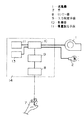
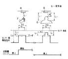
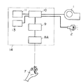
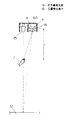
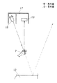
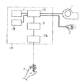
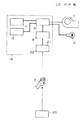
図1〜図4に示すように、下面と前面を開口し、内部に送風機1とランプ2を設けたフード3およびフード3の前面を覆う形状で下面が開口されたフロントフード4によりレンジフード本体5を形成し、運転を制御するためレンジフード本体5の下方にかざした使用者6の手7の位置をレンジフード本体5より下方に向けて距離を計測するように設けたセンサー部8と、センサー部8からの計測信号が所定距離幅で、かつ、所定時間内で入力されたことを判定する入力判定手段9と、この入力判定手段9により判定して送風機1の運転およびランプ2の点灯を制御する制御部10と、送風機1の風量をあらかじめ強、中、弱と設定する風量設定手段11および、レンジフード本体5の下方の調理台12を照射するランプ2のスイッチ13を設けた制御盤14をフロントフード4に設け構成する。
【0011】
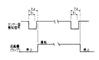
上記構成において、レンジフードを運転するときには、レンジフード本体5の下方に使用者6が手7をかざし一定の範囲移動させることにより、かざした手7は、センサー部8によりレンジフード本体5下方への距離が計測され所定の距離L1内の所定距離幅であることが検知される。制御部10は、図3に示すように入力判定手段9がセンサー部8の検知している時間幅が所定の時間(t1〜t2)内であることによりかざした手6が移動したことを判定すると、送風機1およびランプ2を動作させることとなる。
【0012】
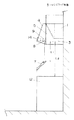
つぎに、かざした手7よりもセンサー部8から遠い距離L2にある調理台12がステンレス等の光の反射率が高い材質で構成されている場合でも、調理台12の位置は、レンジフード本体5下方へ所定の距離外にあり、所定の距離を超えて計測されるのでセンサー部8で検知することはない。
【0013】
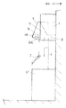
また、レンジフード本体5の下方に使用者6が移動して、センサー部8で所定時間内で検知された場合、図4に示すように頭の距離L3や肩の距離L1は所定距離内であるが、移動したときに計測距離がL1からL3へと変化して所定距離幅Δlを越えることとなり頭を容易に判別することとなる。
【0014】
そして、レンジフードを停止する時はレンジフード本体5の下方に再度手7をかざし、手7を移動することにより、センサー部8からの信号が制御部10に入力され、入力判定手段9により検知している時間を判定したのち、制御部10が運転から停止に切り替わり、送風機1の運転が停止するとともにランプ2は消灯することとなる。
【0015】
このように、本発明の実施の形態1のレンジフードによれば、センサー部8により検知される手7までの距離を計測して、所定の距離内である場合にはセンサー部8で検知され、入力判定手段9により所定の時間内であることが確認されたのちに制御部10が運転を切り替えるので、誤検知することなく、かざした手7を正確に検知することができ、確実にレンジフードの操作ができる。
【0016】
また、センサー部8により検知される物体までの距離は、物体の材質に左右されることなくセンサー部8で計測されるので、レンジフード本体5の下方の調理台12の表面がステンレスで構成されていても制御部10の入力判定手段9により判定がされずレンジフードの運転およびランプ点灯が制御されない。
【0017】
また、センサー部8の検知に所定検知幅を設けることにより、かざした手7とレンジフード本体5の下方を移動する使用者6の頭や体の一部がセンサー部8の検知エリアに入っても区別することができ、正確にかざした手7を判別して、非接触でレンジフードの運転およびランプ2の制御ができる。
【0018】
(実施の形態2)
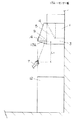
図5〜図7に示すように、センサー部8Aは、赤外線発光部15と、受光面上の赤外線光入射位置によりかざした手7の距離を検知する位置検出素子16とから構成する。
【0019】
上記構成において、レンジフードを運転するときには、使用者6が手7をかざし、一定の範囲手6を移動させることにより、かざした手7は、センサー部8Aで赤外線発光部15の光を反射させて位置検出素子16に入射させてポイントaで検知され、所定の距離内にあることがわかり検知される。
【0020】
そして、一定の距離を手7が動いたことを入力判定手段9によりセンサー部8Aの検知時間幅が所定時間内であることを判定したのち、制御部10が送風機1およびランプ2を動作させることとなる。
【0021】
また、レンジフードの運転を停止するときには、再度手7をかざし移動することにより、運転開始時と同様に作用し、制御部10の動作が運転から停止に切り替わり送風機1が停止およびランプ2が消灯される。
【0022】
つぎに、かざした手7よりも遠い距離にある調理台12がステンレス等の光の反射率が高い材質で構成されている場合、赤外線発光部15の光は図7のような軌跡を通って位置検出素子16の受光面のポイントbへ入射するのでかざした手7の場合と光の強さが同じ光を検知してもポイントの位置から所定距離外(距離が遠い)の反射光であることがわかり検知されない。
【0023】
このように、本発明の実施の形態2のレンジフードによれば、レンジフード本体5の下面部の調理台12の表面がステンレスで構成され赤外線発光部15の発した光が位置検出素子16に反射光として入射してもそのポイントから反射面までの距離をセンサー部8にて判別することができるので、近傍の手7の動きと遠隔のステンレス製調理台による外乱を区別して制御部10にて的確にレンジフードの操作ができる。
【0024】
(実施の形態3)
図8〜図10に示すように、センサー部17に赤外線の発光部18と受光部19を設け、発光部18は、レンジフード本体5に運転を制御するためレンジフード本体5の下方にかざした使用者6の手7の動きを検知するように、鉛直方向に対して光軸が交差する方向に傾けて配設した構成とする。
【0025】
上記構成において、レンジフードを運転するときには、使用者6が手7をかざし、一定の範囲手7を移動させることにより、かざした手7は、センサー部17で赤外線の発光部18の赤外線光を反射させて受光部19に受光させて検知し所定の距離内にあることがわかり検知される。
【0026】
そして、一定の距離を手7が動いたことを入力判定手段9によりセンサー部17の検知時間幅を判定したのち、制御部10が送風機1およびランプ2を動作させることとなる。
【0027】
つぎに、かざした手7よりも遠い距離にある調理台12がステンレス等の光の反射率が高い材質で構成されている場合、赤外線発光部18の光は図10の破線の軌跡を通って反射するが受光部19へは入射しないので調理台12の影響を受けて誤動作することはない。
【0028】
このように、本発明の実施の形態3のレンジフードによれば、レンジフード本体5の下面部の調理台12の表面がステンレスで構成されていても赤外線発光部18の発した光は受光部19に反射光が入射しないため検知されることがなく、近傍の手7の動きと遠隔のステンレス製調理台による外乱を区別して制御部10にて的確にレンジフードの操作ができる。
【0029】
(実施の形態4)
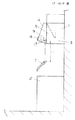
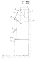
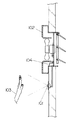
図11および図12に示すように、センサー部17Aは、鉛直方向に対して手前方向に角度を持たして配置し、レンジフード本体下方の調理台12の縁部上方の手の動き検知する構成とする。
【0030】
上記構成において、レンジフードを運転するときには、使用者が手7をかざし、一定の範囲手7を移動させることにより、かざした手7は、センサー部17Aで赤外線の発光部(図示せず)の赤外線光を反射させて受光部(図示せず)に受光させて検知し所定の距離内にあることがわかり検知される。
【0031】
そして、一定の距離を手7が動いたことを入力判定手段9によりセンサー部17Aの検知時間幅を判定したのち、制御部10が送風機1およびランプ2を動作させることとなる。
【0032】
つぎに、かざした手7よりも遠い距離にある調理台12がステンレス等の光の反射率が高い材質で構成されている場合、赤外線発光部の光は図11の破線の軌跡を通るが、調理台12へは当たらないため反射光は受光部へは入射せず、調理台12の影響を受けてレンジフードが誤動作することはない。
【0033】
また、センサー部17Aを鉛直に対して手前方向に角度を持たして配置し、調理台12の縁部上方の手の動きを検知する構成としているので、かざす手7の位置は、調理台12の手前部分で良く、調理作業位置から遠くまで手7を延ばさずに、容易にレンジフードの運転操作を非接触で行うこととなる。
【0034】
このように、本発明の実施の形態4のレンジフードによれば、レンジフード本体5の下面部の調理台12の表面がステンレスで構成されていても赤外線発光部の発した光はレンジフード本体5の下方に配置した調理台12の表面に当たらないので受光部に反射光が入射せず検知されることがなく、近傍の手6の動きと遠隔のステンレス製調理台による外乱を区別して制御部10にて的確にレンジフードの操作ができる。
【0035】
(実施の形態5)
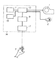
図13〜図15に示すように、下面と前面を開口し、内部に送風機1とランプ2を設けたフード3およびフード3の前面を覆う形状で下面が開口されたフロントフード4によりレンジフード本体5を形成し、運転を制御するためレンジフード本体5の下方にかざした使用者6の手7を検知するようにレンジフード本体5から下方に配置した赤外線発光部20とこの発光部20に対向して前記レンジフード本体5内に配置した受光部21とで構成したセンサー部22と、このセンサー部22からの信号が所定の時間幅で入力されたことを判定する入力判定手段9と、この入力判定手段9により判定して送風機1の運転およびランプ2の点灯を制御する制御部10と、送風機1の風量をあらかじめ強、中、弱と設定する風量設定手段11および、レンジフード本体5の下方の調理台12を照射するランプ2のスイッチ13を設けた制御盤14をフロントフード4に設け構成する。
【0036】
上記構成において、レンジフードを運転するときには、レンジフード本体5の下方に使用者6が手7をかざし一定の範囲移動させることにより、かざした手7は、発光部20の信号が受光部21へ到達するのを遮ることとなり、センサー部22はかざされた手7を検知する。制御部10は、図15に示すように入力判定手段9がセンサー部22の検知している時間幅が所定の時間内であることにより、かざした手7が移動したことを判定すると、送風機1およびランプ2を動作させることとなる。
【0037】
つぎに、かざした手7よりもセンサー部22から遠い距離L2にある調理台12がステンレス等の光の反射率が高い材質で構成されている場合でも、発光部20は調理台12上に配置されていて上方のレンジフード本体5へ向けて発光をしているので調理台12へ光が照射することなく、反射した光の影響を受けることはない。
【0038】
そして、レンジフードを停止するときはレンジフード本体5の下方に再度使用者6がかざした手7を移動することにより、センサー部22からの信号が制御部10に入力され、入力判定手段9によりかざされた手を検知している時間を判定したのち、制御部10が運転から停止に切り替わり、送風機1の運転が停止するとともにランプ2は消灯することとなる。
【0039】
このように、本発明の実施の形態5のレンジフードによれば、センサー部22によりかざした手7を検知して、入力判定手段9により所定の時間であることが確認されたのちに制御部10が運転を切り替えるので、かざした手7を検知することができ、誤検知も防止して、正確にレンジフードの操作ができる。
【0040】
また、レンジフード本体5下面部の調理台12の表面がステンレスで構成されていても影響を受けることなく制御部10の入力判定手段9により正しく判定がされ、レンジフードの運転およびランプ点灯が制御される。
【0041】
【発明の効果】
以上の実施の形態から明らかなように、本発明によれば内部に送風機を設け、調理台の上方に配設されるレンジフード本体と、このレンジフード本体の運転を制御するため、前記レンジフード本体の下方にかざした使用者の手の位置を、レンジフード本体より下方に向けて距離を計測するように設けたセンサー部と、このセンサー部からの信号が入力されたことを判定する入力判定手段と、この入力判定手段により判定して前記送風機の運転を制御する制御部と、前記送風機の風量をあらかじめ設定しておく風量設定手段とを備え、前記センサー部からの計測信号が所定距離幅で所定時間内に入力されたと入力判定手段で判定されたときに前記送風機を運転する構成としたので、誤検知を防止して、スイッチ操作部に非接触状態で正確に運転を制御できるレンジフードを提供できる。
【0042】
また、光の発光部と、この発光部の発する光の到達点上の近い点と遠い点を識別する位置検出素子とを設け、所定の距離内にある手の動きを検知するセンサー部を形成したので、近傍の手の動きと遠隔のステンレス製調理台による外乱を区別して的確にレンジフードを操作することができる。
【0043】
また、少なくとも一つの発光部と受光部からなるセンサー部を設け、前記センサー部の発光部または受光部を鉛直方向に対して光軸が交差する方向に傾けて配設したので、近傍の手の動きと遠隔のステンレス製調理台による外乱を区別して的確にレンジフードを操作することができる。
【0044】
また、センサー部を鉛直方向に対して手前側に傾くように角度をもたして設け、調理台の縁部分上方の手の動きを検知する構成としたので、近傍の手の動きと遠隔のステンレス製調理台による外乱を区別して的確にレンジフードを操作することができる。
【0045】
また、レンジフード本体より下方に向けた赤外線の受光部と、調理台に設け、前記レンジフード本体に向けて光を発行する赤外線の発光部によりセンサー部を形成したので、誤検知が防止され正確にレンジフードの操作ができる。
【0046】
なお、本発明の実施形態では、センサー部の検知信号を入力判定手段により確認したのちに制御部が運転を制御する構成としたが、センサー部が検知信号の確認を行い、かざした手の有無を判定したのちに制御部でレンジフードの運転を制御する構成としてもその作用効果に差のないことは言うまでもない。
【図面の簡単な説明】
【図1】本発明の実施形態1のレンジフードの制御構成を示すブロック図
【図2】同レンジフードの設置状態の制御の構成を示す側面図
【図3】同レンジフードの検知信号の発生例を示すタイムチャート
【図4】同レンジフードの検知信号の計測距離と発生時間を示すチャート
【図5】本発明の実施形態2のレンジフードの設置状態の構成を示す側面図
【図6】同レンジフードの制御の構成を示すブロック図
【図7】同レンジフードのセンサー部の構成を示す側断面図
【図8】本発明の実施形態3のレンジフードの設置状態の構成を示す側面図
【図9】同レンジフードの制御の構成を示すブロック図
【図10】同レンジフードのセンサー部の構成を示す側断面図
【図11】本発明の実施形態4のレンジフードの設置状態の構成を示す側面図
【図12】同レンジフードの制御の構成を示すブロック図
【図13】本発明の実施形態5のレンジフードの設置状態の構成を示す側面図
【図14】同レンジフードの制御の構成を示すブロック図
【図15】同レンジフードの検知信号の発生時間を示すタイムチャート
【図16】従来の換気扇の設置状態の構成を示す断面図
【符号の説明】
1 送風機
5 レンジフード本体
6 使用者
7 手
8 センサー部
8A センサー部
9 入力判定手段
10 制御部
11 風量設定手段
12 調理台
15 赤外線発光部
16 位置検出素子
17 センサー部
17A センサー部
18 発光部
18A 発光部
19 受光部
19A 受光部
20 発光部
21 受光部
22 センサー部[0001]
BACKGROUND OF THE INVENTION
The present invention relates to a range hood installed above a cooking table that enables operation control of a blower in a non-contact state with a switch or the like.
[0002]
[Prior art]
In recent years, the range hood that discharges the oily smoke generated during cooking to the outdoors has become widespread as the chances of cooking at home increase, and the control switch can be brought into a non-contact state for further convenience. There is a growing demand for range hoods that can easily control operation.
[0003]
Conventionally, as this type of ventilation fan, one described in JP-A-5-340576 is known. The configuration will be described below with reference to FIG. As shown in the figure, when the
[0004]
[Problems to be solved by the invention]
In such a conventional ventilation fan configuration, the detection area expands to detect using a pyroelectric human sensor or a reflective ultrasonic sensor, and even if a hand or human body during cooking is detected Therefore, there is a problem that it is judged that the hand is held up in order to control the operation, which causes a malfunction and poor usability.
[0005]
In addition, a reflection type sensor equipped with an infrared light emitting part and a light receiving part that detects human hands has been studied, but detection is performed based on the intensity of the reflected wave of the infrared signal emitted by the sensor itself. Therefore, even if a predetermined area is set, the predetermined area changes for each object to be reflected that has a different reflection coefficient, and malfunctions may occur due to the influence of a stainless steel cooking table farther than the human hand. In some cases, the movement of the hand could not be detected correctly.
[0006]
The present invention solves the above-described problem, and detects a user's hand held below the range hood body using a sensor unit that measures the position of the detection body, and operates accurately even in a non-contact state with the switch unit. It aims at providing the range hood which can be operated.
[0007]
[Means for Solving the Problems]
In the range hood of the present invention, an air blower is provided inside, the range hood main body disposed above the cooking table, and the user holding the range hood main body under the range hood main body in order to control the operation of the range hood main body. A sensor unit provided to measure the distance with the hand facing downward from the range hood main body, an input determination unit that determines that a signal from the sensor unit is input, and the input determination unit that determines the input A control unit that controls the operation of the blower; and an air volume setting unit that sets the air volume of the blower in advance; and an input determination unit that the measurement signal from the sensor unit is input within a predetermined time with a predetermined distance width The air blower is operated when it is determined in (4).
[0008]
According to the present invention, it is possible to provide a range hood capable of detecting a user's hand held below the range hood main body and accurately performing a driving operation even in a non-contact state with the switch portion.
[0009]
DETAILED DESCRIPTION OF THE INVENTION
The invention according to claim 1 of the present invention is provided with a blower inside, and a range hood body disposed above the cooking table, and is held under the range hood body in order to control the operation of the range hood body. A sensor unit provided to measure the distance with the position of the user's hand facing down the range hood body, input determination means for determining that a signal from the sensor unit has been input, and this input determination And a control unit for controlling the operation of the blower as determined by the means, and an air volume setting unit for presetting the air volume of the blower, and a measurement signal from the sensor unit is input within a predetermined time with a predetermined distance width When it is determined by the input determining means that the fan is operated, the range hood is configured such that a hand held under the hood is detected by the sensor unit. Ri, is recognized to be a motion of the hand held over consciously in order to control the operation, the erroneous detection is prevented, an effect that is precisely controlled.
[0010]
Embodiments of the present invention will be described below with reference to FIGS.
(Embodiment 1)
As shown in FIGS. 1 to 4, the range hood main body is formed by a
[0011]
In the above configuration, when the range hood is operated, the
[0012]
Next, even when the cooking table 12 located at a distance L2 farther from the
[0013]
When the
[0014]
When the range hood is stopped, the
[0015]
As described above, according to the range hood of the first embodiment of the present invention, the distance to the
[0016]
Further, since the distance to the object detected by the
[0017]
Further, by providing a predetermined detection width for the detection of the
[0018]
(Embodiment 2)
As shown in FIGS. 5 to 7, the
[0019]
In the above configuration, when driving the range hood, the
[0020]
Then, after determining that the
[0021]
Further, when the operation of the range hood is stopped, the
[0022]
Next, when the cooking table 12 at a distance farther than the
[0023]
Thus, according to the range hood of
[0024]
(Embodiment 3)
As shown in FIGS. 8 to 10, an infrared
[0025]
In the above configuration, when driving the range hood, the
[0026]
And after determining the detection time width of the
[0027]
Next, when the cooking table 12 at a distance farther than the
[0028]
Thus, according to the range hood of
[0029]
(Embodiment 4)
As shown in FIGS. 11 and 12, the
[0030]
In the above configuration, when operating the range hood, the user holds the
[0031]
And after determining the detection time width of the
[0032]
Next, when the cooking table 12 at a distance farther than the
[0033]
In addition, the
[0034]
Thus, according to the range hood of
[0035]
(Embodiment 5)
As shown in FIGS. 13 to 15, the range hood main body is formed by a
[0036]
In the above configuration, when operating the range hood, the
[0037]
Next, even when the cooking table 12 located at a distance L2 farther from the
[0038]
When the range hood is stopped, the signal from the
[0039]
As described above, according to the range hood of the fifth embodiment of the present invention, after the
[0040]
Further, even if the surface of the
[0041]
【The invention's effect】
As is clear from the above embodiments, according to the present invention, the range hood main body provided in the interior and disposed above the cooking table, and the range hood main body are controlled in order to control the operation of the range hood main body. A sensor unit provided to measure the distance of the user's hand held below the main unit downward from the range hood main unit, and an input determination that determines whether a signal is input from the sensor unit Means, a control unit for controlling the operation of the blower determined by the input determination unit, and an air volume setting unit for presetting the air volume of the blower, and the measurement signal from the sensor unit has a predetermined distance width The fan is operated when it is determined by the input determining means that it has been input within a predetermined time in order to prevent erroneous detection and accurately operate in a non-contact state with the switch operation unit. It is possible to provide a control can range hood.
[0042]
Also, a light emitting part and a position detecting element for identifying a near point and a far point on the arrival point of the light emitted by the light emitting part are provided, and a sensor part for detecting the movement of the hand within a predetermined distance is formed. Therefore, the range hood can be accurately operated by distinguishing between the nearby hand movement and the disturbance caused by the remote stainless steel cooking table.
[0043]
In addition, a sensor unit including at least one light emitting unit and a light receiving unit is provided, and the light emitting unit or the light receiving unit of the sensor unit is disposed so as to be inclined in a direction in which the optical axis intersects the vertical direction. The range hood can be operated accurately by distinguishing movement and disturbance from a remote stainless steel cooking table.
[0044]
In addition, the sensor unit is provided at an angle so as to incline toward the front side with respect to the vertical direction, and it is configured to detect the movement of the hand above the edge of the cooking table. The range hood can be operated accurately by distinguishing the disturbance caused by the stainless steel cooking table.
[0045]
In addition, the sensor part is formed by the infrared light receiving part that is directed downward from the range hood body and the infrared light emitting part that is provided on the cooking table and emits light toward the range hood body. The range hood can be operated.
[0046]
In the embodiment of the present invention, the control unit is configured to control the operation after confirming the detection signal of the sensor unit by the input determination unit, but the sensor unit confirms the detection signal and whether or not the hand is held up. It goes without saying that there is no difference in the operation and effect even if the control unit controls the operation of the range hood after determining the above.
[Brief description of the drawings]
FIG. 1 is a block diagram showing a control configuration of a range hood according to a first embodiment of the present invention. FIG. 2 is a side view showing a control configuration of an installation state of the range hood. Fig. 4 is a time chart showing an example. Fig. 4 is a chart showing measurement distances and generation times of detection signals of the same range hood. Fig. 5 is a side view showing a configuration of a range hood installation state according to the second embodiment of the present invention. FIG. 7 is a side cross-sectional view showing the configuration of the sensor unit of the same range hood. FIG. 8 is a side view showing the configuration of the range hood according to the third embodiment of the present invention. FIG. 9 is a block diagram showing a configuration of control of the same range hood. FIG. 10 is a side sectional view showing a configuration of a sensor section of the same range hood. FIG. 11 shows a configuration of an installed state of the range hood according to the fourth embodiment of the present invention. Side view showing 12 is a block diagram showing the configuration of the range hood. FIG. 13 is a side view showing the configuration of the range hood according to the fifth embodiment of the present invention. FIG. 14 is a block diagram showing the configuration of the range hood. FIG. 15 is a time chart showing the generation time of the detection signal of the same range hood. FIG. 16 is a cross-sectional view showing the configuration of a conventional ventilation fan installed.
DESCRIPTION OF SYMBOLS 1
Claims (4)
Priority Applications (1)
| Application Number | Priority Date | Filing Date | Title |
|---|---|---|---|
| JP11048298A JP3607073B2 (en) | 1998-04-21 | 1998-04-21 | Range food |
Applications Claiming Priority (1)
| Application Number | Priority Date | Filing Date | Title |
|---|---|---|---|
| JP11048298A JP3607073B2 (en) | 1998-04-21 | 1998-04-21 | Range food |
Publications (2)
| Publication Number | Publication Date |
|---|---|
| JPH11304204A JPH11304204A (en) | 1999-11-05 |
| JP3607073B2 true JP3607073B2 (en) | 2005-01-05 |
Family
ID=14536855
Family Applications (1)
| Application Number | Title | Priority Date | Filing Date |
|---|---|---|---|
| JP11048298A Expired - Fee Related JP3607073B2 (en) | 1998-04-21 | 1998-04-21 | Range food |
Country Status (1)
| Country | Link |
|---|---|
| JP (1) | JP3607073B2 (en) |
Families Citing this family (2)
| Publication number | Priority date | Publication date | Assignee | Title |
|---|---|---|---|---|
| CN105811952B (en) * | 2016-04-19 | 2018-11-06 | 广东超人节能厨卫电器有限公司 | Invisible intelligent switch |
| CN116928712B (en) * | 2023-06-30 | 2026-02-27 | 纯米科技(上海)股份有限公司 | A desktop range hood |
-
1998
- 1998-04-21 JP JP11048298A patent/JP3607073B2/en not_active Expired - Fee Related
Also Published As
| Publication number | Publication date |
|---|---|
| JPH11304204A (en) | 1999-11-05 |
Similar Documents
| Publication | Publication Date | Title |
|---|---|---|
| US6212697B1 (en) | Automatic flusher with bi-modal sensitivity pattern | |
| US6782660B2 (en) | Automatic door sensor | |
| JPH07301522A (en) | Non-contact control device and method thereof | |
| US4859869A (en) | Safety switching means for controlling a current consumer | |
| JPH05340548A (en) | Heating cooker | |
| JP3607073B2 (en) | Range food | |
| JP6163481B2 (en) | Vehicle control structure | |
| JP2976465B2 (en) | Kitchen equipment | |
| JP6019394B2 (en) | Sanitary washing device | |
| JP7398690B2 (en) | Stove | |
| JP4424089B2 (en) | Kitchen equipment | |
| JPH0689782A (en) | Lighting automatic flashing device | |
| JP5974286B2 (en) | Sanitary washing device | |
| RU2597072C2 (en) | Control panel for measuring instrument | |
| JP2010035836A (en) | Modular kitchen | |
| JP2003194380A (en) | Range hood fan | |
| JP7427186B2 (en) | Stove | |
| JP2600563Y2 (en) | Toilet bowl with local cleaning device | |
| JPH11318760A (en) | Hand drying device | |
| US20250060830A1 (en) | Gesture interface control of a mobile storage system | |
| JP2003156572A (en) | Electrical component for toilet stool | |
| JP3097207B2 (en) | Lighting equipment | |
| JP5974285B2 (en) | Sanitary washing device | |
| JP2000336716A (en) | Automatic faucet | |
| CN223786041U (en) | Touchless induction switch structure |
Legal Events
| Date | Code | Title | Description |
|---|---|---|---|
| A977 | Report on retrieval |
Free format text: JAPANESE INTERMEDIATE CODE: A971007 Effective date: 20040308 |
|
| A131 | Notification of reasons for refusal |
Free format text: JAPANESE INTERMEDIATE CODE: A131 Effective date: 20040316 |
|
| A521 | Written amendment |
Free format text: JAPANESE INTERMEDIATE CODE: A523 Effective date: 20040512 |
|
| A02 | Decision of refusal |
Free format text: JAPANESE INTERMEDIATE CODE: A02 Effective date: 20040608 |
|
| A521 | Written amendment |
Free format text: JAPANESE INTERMEDIATE CODE: A523 Effective date: 20040804 |
|
| A911 | Transfer of reconsideration by examiner before appeal (zenchi) |
Free format text: JAPANESE INTERMEDIATE CODE: A911 Effective date: 20040823 |
|
| TRDD | Decision of grant or rejection written | ||
| A01 | Written decision to grant a patent or to grant a registration (utility model) |
Free format text: JAPANESE INTERMEDIATE CODE: A01 Effective date: 20040914 |
|
| A61 | First payment of annual fees (during grant procedure) |
Free format text: JAPANESE INTERMEDIATE CODE: A61 Effective date: 20041006 |
|
| R150 | Certificate of patent or registration of utility model |
Free format text: JAPANESE INTERMEDIATE CODE: R150 |
|
| LAPS | Cancellation because of no payment of annual fees |