JP3607046B2 - Image reading device - Google Patents
Image reading device Download PDFInfo
- Publication number
- JP3607046B2 JP3607046B2 JP17865097A JP17865097A JP3607046B2 JP 3607046 B2 JP3607046 B2 JP 3607046B2 JP 17865097 A JP17865097 A JP 17865097A JP 17865097 A JP17865097 A JP 17865097A JP 3607046 B2 JP3607046 B2 JP 3607046B2
- Authority
- JP
- Japan
- Prior art keywords
- image
- film
- reading
- unit
- image data
- Prior art date
- Legal status (The legal status is an assumption and is not a legal conclusion. Google has not performed a legal analysis and makes no representation as to the accuracy of the status listed.)
- Expired - Fee Related
Links
- 238000012937 correction Methods 0.000 claims description 52
- 230000001678 irradiating effect Effects 0.000 claims description 2
- 238000001444 catalytic combustion detection Methods 0.000 description 140
- 238000012545 processing Methods 0.000 description 93
- 238000000034 method Methods 0.000 description 44
- 230000015654 memory Effects 0.000 description 19
- 230000000875 corresponding effect Effects 0.000 description 16
- 230000003287 optical effect Effects 0.000 description 15
- 238000010586 diagram Methods 0.000 description 8
- 230000002950 deficient Effects 0.000 description 7
- 238000000926 separation method Methods 0.000 description 7
- 238000006243 chemical reaction Methods 0.000 description 5
- 238000009825 accumulation Methods 0.000 description 4
- 238000004891 communication Methods 0.000 description 4
- 238000004140 cleaning Methods 0.000 description 3
- 238000011161 development Methods 0.000 description 3
- 238000009792 diffusion process Methods 0.000 description 3
- 230000010365 information processing Effects 0.000 description 3
- 229920006395 saturated elastomer Polymers 0.000 description 3
- 239000000758 substrate Substances 0.000 description 3
- 238000006073 displacement reaction Methods 0.000 description 2
- 230000000694 effects Effects 0.000 description 2
- 238000003780 insertion Methods 0.000 description 2
- 230000037431 insertion Effects 0.000 description 2
- 239000007788 liquid Substances 0.000 description 2
- 230000010355 oscillation Effects 0.000 description 2
- 230000005856 abnormality Effects 0.000 description 1
- 238000003491 array Methods 0.000 description 1
- 238000007664 blowing Methods 0.000 description 1
- 230000006835 compression Effects 0.000 description 1
- 238000007906 compression Methods 0.000 description 1
- 230000001276 controlling effect Effects 0.000 description 1
- 230000002596 correlated effect Effects 0.000 description 1
- 230000006837 decompression Effects 0.000 description 1
- 230000007423 decrease Effects 0.000 description 1
- 230000001934 delay Effects 0.000 description 1
- 238000001514 detection method Methods 0.000 description 1
- 238000001035 drying Methods 0.000 description 1
- 235000013399 edible fruits Nutrition 0.000 description 1
- 229910052736 halogen Inorganic materials 0.000 description 1
- 150000002367 halogens Chemical class 0.000 description 1
- 238000003702 image correction Methods 0.000 description 1
- 238000003384 imaging method Methods 0.000 description 1
- 239000000463 material Substances 0.000 description 1
- 239000011159 matrix material Substances 0.000 description 1
- 229910001507 metal halide Inorganic materials 0.000 description 1
- 150000005309 metal halides Chemical class 0.000 description 1
- 238000012544 monitoring process Methods 0.000 description 1
- 238000001454 recorded image Methods 0.000 description 1
- 238000005070 sampling Methods 0.000 description 1
- 239000004065 semiconductor Substances 0.000 description 1
- 238000009966 trimming Methods 0.000 description 1
- 238000005406 washing Methods 0.000 description 1
- XLYOFNOQVPJJNP-UHFFFAOYSA-N water Substances O XLYOFNOQVPJJNP-UHFFFAOYSA-N 0.000 description 1
Images


Landscapes
- Facsimile Scanning Arrangements (AREA)
- Facsimiles In General (AREA)
Description
【0001】
【発明の属する技術分野】
本発明は、画像読取装置に係り、特に、画像に対して予備読み取りを行い、予備読み取りの結果に基づいて前記画像の本読み取りを行う際の読取条件を決定し、該読取条件で前記画像の本読み取りを行う画像読取装置に関する。
【0002】
【従来の技術】
従来より、写真フィルムに記録されているフィルム画像を、CCD等の読取センサを備えた画像読取装置によって読み取り、該読み取りによって得られた画像データに対して各種の補正等の画像処理を行った後に、記録材料への画像の記録やディスプレイへの画像の表示等を行う画像処理システムが知られている。
【0003】
またフィルム画像(特にネガフィルムに記録されたネガ画像)はラチチュードが広く濃度が低い画像から濃度が高い画像まで、種々の濃度の画像が存在するので、所望の画質の記録画像や表示画像を得るために、画像読取装置ではフィルム画像を予備的に読み取り(所謂、プレスキャン)、フィルム画像の濃度等に応じた読取条件(例えば、フィルム画像に照射する光の光量やCCDの電荷蓄積時間等)を決定し、決定した読取条件でフィルム画像を読み取っていた(所謂、ファインスキャン)。
【0004】
【発明が解決しようとする課題】
通常、プレスキャンでは画像読取装置によりフィルム上の画像を素早く、粗く読み取り、読み取った画像データに基づいてファインスキャン時の読取条件(露光量、フィルタ挿入量等)、画像処理条件を決定するためのセットアップ演算を行う。プレスキャンでは常に一定の読取条件(露光量、フィルタ挿入量)でフィルム画像を読み取るが、この時のフィルム画像に照射される光量は濃度の低いフィルムを読み取っても読取センサの出力が飽和しない程度の光量に設定されている。この場合に露光過多のネガフィルム(オーバネガフィルム)や露光不足のリバーサルフィルム(アンダーリバーサルフィルム)等の濃度の高いフィルムをプレスキャンで読み取ると、読取センサが受光する光量が少なくなり、SN比が悪い画像データしか取り込めず、セットアップ演算の誤差が大きくなるという問題が有った。
【0005】
一方、リバーサルフィルムを使用する撮影者は明確な撮影意図を持ったプロカメラマン、セミプロ等のカメラマンが多く、撮影されたフィルム画像の暗い部分をつぶしても明るい部分を強調して表現する、あるいはその逆に明るい部分をつぶしても暗い部分を強調して表現するということが行われる。またリバーサルフィルムはフィルムの再現域が広いという特性を有している。
【0006】
本発明はこのような事情に鑑みてなされたものであり、プレスキャンで読み取った画像データに基づいてファインスキャン時の読取条件及びファインスキャンにより得られた画像データの画像処理条件を決定するためのセットアップ演算の精度の向上を図り、高濃度の画像を精度良く読み取ることができる画像読取装置を提供することを目的とする。
【0007】
【課題を解決するための手段】
上記目的を達成するために請求項1に記載の発明は、原稿に光を照射してその透過光の受光量に基づいて画像を読み取る読取手段と、該読取手段が画像の予備読み取りを行った結果に基づいて前記画像の本読み取りを行う際の読取条件を決定する決定手段と、前記読取手段が画像の予備読み取りを行った結果に基づいて濃度が高いフィルム画像か否かを判定する判定手段と、前記読取手段により画像の予備読み取りを行わせ、該予備読み取りの結果から前記決定手段によって決定された読取条件で画像の本読み取りを行せると共に、前記判定手段により濃度が高いフィルム画像であると判定された場合には、前記濃度が高いフィルム画像に対する予備読み取りを前記読取手段の受光量を増加させて再度行わせた後に、該再度の予備読み取りの結果から前記決定手段によって決定された読取条件で前記画像の本読み取りを行わせる制御手段と、を有することを特徴とする。
【0008】
上記構成の画像読取装置では読取手段が画像の予備読み取りを行った結果に基づいて決定手段は前記画像の本読み取りを行う際の読取条件を決定し、判定手段は読取手段が画像の予備読み取りを行った結果に基づいて濃度が高いフィルム画像か否かを判定する。制御手段は前記読取手段により画像の予備読み取りを行わせ、該予備読み取りの結果から前記決定手段によって決定された読取条件で画像の本読み取りを行せると共に、前記判定手段により濃度が高いフィルム画像であると判定された場合には、前記濃度が高いフィルム画像に対する予備読み取りを前記読取手段の受光量を増加させて再度行わせた後に、該再度の予備読み取りの結果から前記決定手段によって決定された読取条件で前記画像の本読み取りを行わせる。
【0009】
請求項1に記載の発明によれば、予備読み取りを再度行う必要があると判定された画像が有った場合には、この画像に対する予備読み取りを読取手段の受光量を増加させて再度行わせた後に、該再度の予備読み取りの結果から決定手段によって決定された読取条件で前記画像の本読み取りを行わせるようにしたので、予備読み取りの読取条件では精度良く読み取ることが困難な画像についても再度の予備読み取りでSN比の高い状態で前記画像の読み取りを行うことができ、それ故プレスキャンで読み取った画像データに基づいてファインスキャン時の読取条件及びファインスキャンにより得られた画像データの画像処理条件を決定するためのセットアップ演算の精度の向上が図れ、高濃度の画像を精度良く読み取ることができる。
【0010】
また請求項2に記載の発明は、請求項1に記載の画像読取装置において、前記画像は、ネガフィルムに記録された複数のフィルム画像であることを特徴とする。
【0011】
上記構成の画像読取装置では、読取対象となる画像は長尺状のネガフィルムに記録された複数のフィルム画像であり、制御手段は、読取手段により行われたフィルム画像の予備読み取りの結果に基づいて判定手段により濃度が高いフィルム画像であると判定されたフィルム画像について予備読み取りを前記読取手段の受光量を増加させて再度行わせる。
【0012】
請求項2に記載の発明によれば、判定手段により予備読み取りの結果からた濃度の高いと判定されたネガフィルムのフィルム画像について制御手段により同一条件で再度、予備読み取りを前記読取手段の受光量を増加させて行われるので、濃度の高いネガフィルムのフィルム画像を精度良く読み取ることができる。
【0013】
更に請求項3に記載の発明は、請求項1に記載の画像読取装置において、前記複数の画像は、リバーサルフィルムに記録されたフィルム画像であり、フィルム画像の濃度補正を指示する指示手段を更に有し、前記判定手段は、前記指示手段により濃度補正の指示が有り、かつ指示された濃度補正量が大きく、かつフィルム画像の濃度が高い場合に予備読み取りを再度行う必要があると判定することを特徴とする。
【0014】
上記構成の画像読取装置では、読取手段によるフィルム画像の予備読み取りの結果をディスプレイに表示させてモニタしながら、キーボード等の指示手段により濃度の高いリバーサルフィルムのフィルム画像について濃度補正を指示することが可能である。
【0015】
判定手段は、前記指示手段により濃度補正の指示が有り、かつ指示された濃度補正量が大きく、かつフィルム画像の濃度が高い場合に予備読み取りを再度行う必要があると判定する。
【0016】
請求項3に記載の発明によれば、判定手段により前記指示手段により濃度補正の指示が有り、かつ指示された濃度補正量が大きく、かつフィルム画像の濃度が高い場合に再度、予備読み取りを前記読取手段の受光量を増加させて行われるので、撮影者の意図を反映した上でリバーサルフィルムに記録された濃度の高いフィルム画像を精度良く読み取ることができる。
【0017】
【発明の実施の形態】
以下、図面を参照して本発明の実施形態について詳細に説明する。なお、以下では、まず本発明の第1の実施形態に係る画像読取装置の一例としてディジタルラボシステムについて説明する。
【0018】
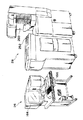
(システム全体の概略構成)
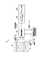
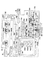
図1には本実施形態に係るディジタルラボシステム10が示されている。このラボシステム10は、図13にその外観を示すようにエリアCCDスキャナ12、ラインCCDスキャナ14、及び画像処理部16を備えた入力部26と、レーザプリンタ部18及びプロセッサ部20を備えた出力部28と、で構成されている。
【0019】
エリアCCDスキャナ12及びラインCCDスキャナ14は、ネガフィルムやリバーサルフィルム等の写真フィルムに記録されているフィルム画像を読み取るためのものであり、例えばエリアCCDスキャナ12は135サイズの写真フィルム、110サイズの写真フィルム、及び透明な磁気層が形成された写真フィルム(240サイズの写真フィルム:所謂APSフィルム)のフィルム画像を読取対象とし、ラインCCDスキャナ14は120サイズ及び220サイズ(ブローニサイズ)の写真フィルムのフィルム画像を読取対象とすることができる。
【0020】
エリアCCDスキャナ12及びラインCCDスキャナ14は、上記の読取対象のフィルム画像をエリアCCD又はラインCCDで読み取り、画像データを出力する。なお、ディジタルラボシステム10は、必ずしもエリアCCDスキャナ12及びラインCCDスキャナ14の両方を備えている必要はなく、例えばフィルム画像の読み取りを行う写真フィルムのサイズが限られている場合は、エリアCCDスキャナ12及びラインCCDスキャナ14の何れか一方(例えばエリアCCDスキャナ12)のみを設けることも可能である。なお、エリアCCDスキャナ12は本発明の読取手段に対応している。
【0021】
画像処理部16は、エリアCCDスキャナ12やラインCCDスキャナ14から出力された画像データ(スキャン画像データ)が入力されると共に、デジタルカメラでの撮影によって得られた画像データ、フィルム画像以外の原稿(例えば反射原稿等)をスキャナで読み取ることで得られた画像データ、コンピュータで生成された画像データ等(以下、これらをファイル画像データと総称する)を外部から入力する(例えば、メモリカード等の記憶媒体を介して入力したり、通信回線を介して他の情報処理機器から入力する等)ことも可能なように構成されている。
【0022】
画像処理部16は、入力された画像データに対して各種の補正等の画像処理を行って、記録用画像データとしてレーザプリンタ部18へ出力する。また、画像処理部16は、画像処理を行った画像データを画像ファイルとして外部へ出力する(例えばメモリカード等の記憶媒体に出力したり、通信回線を介して他の情報処理機器へ送信する等)ことも可能とされている。
【0023】
レーザプリンタ部18はR、G、Bのレーザ光源を備えており、画像処理部16から入力された記録用画像データに応じて変調したレーザ光を印画紙に照射して、走査露光によって印画紙に画像を記録する。また、プロセッサ部20は、レーザプリンタ部18で走査露光によって画像が記録された印画紙に対し、発色現像、漂白定着、水洗、乾燥の各処理を施す。これにより、印画紙上に画像が形成される。
【0024】
(エリアCCDスキャナの構成)
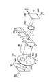
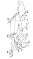
次にエリアCCDスキャナ12の構成について説明する。図2にはエリアCCDスキャナ12の光学系の概略構成が示されている。この光学系は、ハロゲンランプやメタルハライドランプ等から成り写真フィルム22に光を照射する光源30を備えており、光源30の光射出側には、写真フィルム22に照射する光の光量を調節するための絞り32、色分解フィルタユニット34、写真フィルム22に照射する光を拡散光とする光拡散ボックス36が順に配置されている。色分解フィルタユニット34は、R、G、Bの色分解フィルタ34R、34G、34Bが、図2矢印A方向に沿って回転可能とされたターレット34Aに嵌め込まれて構成されている。
【0025】
写真フィルム22は、フィルムキャリア38(図5参照、図2では図示省略)によってフィルム画像の画面中心が光軸Lに一致するように位置決めされる。なお、図2では長尺状の写真フィルム22を示しているが、1コマ毎にスライド用のホルダに保持されたスライドフィルム(リバーサルフィルム)やAPSフィルムについては、各々専用のフィルムキャリアが用意されており(APSフィルム用のフィルムキャリアは磁気層に磁気記録された情報を読み取る磁気ヘッドを有している)、これらの写真フィルムのフィルム画像を位置決めすることも可能とされている。
【0026】
写真フィルム22を挟んで光源30と反対側には、光軸Lに沿って、フィルム画像を透過した光を結像させるレンズユニット40、エリアCCD42が順に配置されている。図2ではレンズユニット40として単一のレンズのみを示しているが、レンズユニット40は、実際には複数枚のレンズから構成されたズームレンズである。エリアCCD42は多数のCCDセルがマトリックス状に配列されたモノクロのCCDであり、受光面がレンズユニット40の結像点位置に一致するように配置されている。
【0027】
また、エリアCCD42にはピエゾアクチュエータ44X、44Yが取付けられている。ピエゾアクチュエータは電圧を加えると歪んで変位を発生するものであり、ピエゾアクチュエータ44X、44Yは、変位の発生方向がエリアCCD42の画素の配列方向(図2の矢印X方向及び矢印Y方向)に沿うように配置されている。また、図示は省略するが、エリアCCD42とレンズユニット40との間にはシャッタが設けられている。
【0028】
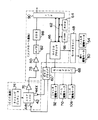
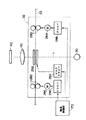
図3にはエリアCCDスキャナ12の電気系の概略構成が示されている。コントロール基板には、エリアCCDスキャナ12全体の制御を司るマイクロプロセッサ46が搭載されている。マイクロプロセッサ46にはモータドライバ48が接続されており、モータドライバ48には、絞り32をスライド移動させる絞り駆動モータ50、色分解フィルタユニット34のターレット34Aを回転させるフィルタ駆動モータ54が接続されている。
【0029】
マイクロプロセッサ46は、図示しない電源スイッチのオンオフに連動して光源30を点消灯させる。また、マイクロプロセッサ46は、エリアCCD42によるフィルム画像の読み取り(測光)を行う際に、フィルタ駆動モータ54によってターレット34Aを回転させる。従ってフィルム画像は、エリアCCD42により各成分色毎に順に読み取られることになる。またマイクロプロセッサ46は、絞り駆動モータ50により絞り32をスライド移動させ、エリアCCD42に入射される光量を調節する。
【0030】
また、マイクロプロセッサ46にはピエゾドライバ60を介してピエゾアクチュエータ44X、44Yが接続されている。マイクロプロセッサ46は、単一のフィルム画像に対し、エリアCCD42によって各成分色毎に各々4回読み取りを行わせると共に、各回の読み取りにおいて、ピエゾアクチュエータ44X、44Yにより、エリアCCD42の位置を図2のX方向又はY方向に移動させる。
【0031】
また、マイクロプロセッサ46にはバス62を介してRAM64(例えばSRAM)、ROM66(例えば記憶内容を書換え可能なROM)が接続されていると共に、モータドライバ68が接続されている。モータドライバ68には、レンズユニット40の複数枚のレンズの位置を相対的に移動させることでレンズユニット40のズーム倍率を変更するズーム駆動モータ70、レンズユニット40全体を移動させることでレンズユニット40の結像点位置を光軸Lに沿って移動させるレンズ駆動モータ106が接続されている。マイクロプロセッサ46は、フィルム画像のサイズやトリミングを行うか否か等に応じて、ズーム駆動モータ70によってレンズユニット40のズーム倍率を所望の倍率に変更する。
【0032】
一方、エリアCCD42は、タイミングジェネレータ74と共にCCD基板に搭載されている。
【0033】
タイミングジェネレータ74は、エリアCCD42や後述するA/D変換器82等を動作させるための各種のタイミング信号(クロック信号)を発生する。またタイミングジェネレータ74はマイクロプロセッサ46からの指令に基づいてエリアCCD42の各CCDセルにおける電荷蓄積時間を変更するように制御するタイミング信号を出力するようになっている。
【0034】
エリアCCD42の信号出力端は、CCD基板に搭載された増幅器76、コントロール基板に搭載された増幅器78、80を介してA/D変換器82に接続されている。A/D変換器82の出力端は、相関二重サンプリング回路(CDS)88を介してインタフェース(I/F)回路90に接続されている。CDS88では、フィードスルー信号のレベルを表すフィードスルーデータ及び画素信号のレベルを表す画素データを各々サンプリングし、各画素毎に画素データからフィードスルーデータを減算する。そして、演算結果(各CCDセルでの蓄積電荷量に正確に対応する画素データ)を、I/F回路90を介してスキャン画像データとして画像処理部16へ順次出力する。
【0035】
また、モータドライバ68には、シャッタを開閉させるシャッタ駆動モータ92が接続されている。エリアCCD42の暗出力については、後段の画像処理部16で補正されるが、暗出力レベルは、フィルム画像の読み取りを行っていないときに、マイクロプロセッサ46がシャッタを閉止させることで得ることができる。
【0036】
(ラインCCDスキャナの構成)
次にラインCCDスキャナ14の構成について説明する。なお、エリアCCDスキャナ12と同一の部分には同一の符号を付して説明を省略し、エリアCCDスキャナ12と異なる部分についてのみ説明する。
【0037】
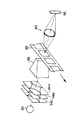
図4にはラインCCDスキャナ14の光学系の概略構成が示されている。この光学系は、光源30と光拡散ボックス36との間に、絞り32及び色分解フィルタユニット34に代えて、C(シアン)、M(マゼンダ)、Y(イエロー)の調光フィルタ114C、114M、114Yが射出光の光軸Lに沿って順に設けられており、エリアCCD42に代えてラインCCD116が設けられている。本実施形態では、ラインCCD116として、CCDセルがライン状に配列されて成るCCDセル列が3ライン設けられ、各ラインの光入射側にR、G、Bの色分解フィルタの何れかが各々取付けられた3ラインカラーCCDを用いている。
【0038】
ラインCCDスキャナ14の電気系の構成については図示を省略するが、フィルタ駆動モータ54は、調光フィルタ114C、114M、114Yを各々独立に移動可能とされている。また、ラインCCD116からはR、G、Bの測光信号が並列に出力されるので、図3に示した増幅器76、78、80、A/D変換器82、CDS88から成る信号処理系も3系統設けられており、I/F回路90からは、スキャン画像データとしてR、G、Bの画像データが並列に出力される。
【0039】
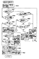
(画像処理部の構成)
次に画像処理部16の構成について図5を参照して説明する。画像処理部16は、エリアCCDスキャナ12に対応してエリアスキャナ補正部120が設けられていると共に、ラインCCDスキャナ14に対応してラインスキャナ補正部122が設けられている。
【0040】
エリアスキャナ補正部120は、暗補正回路124、欠陥画素補正部128、明補正回路130を備えている。暗補正回路124は、エリアCCD42の光入射側がシャッタにより遮光されている状態で、エリアCCDスキャナ12から入力された画像データ(エリアCCD42の暗出力レベルを表すデータ)を各画素毎に記憶しておき、エリアCCDスキャナ12から入力されたスキャン画像データから各画素毎に前記暗出力レベルを減ずることによって補正する。
【0041】
また、エリアCCD42の光電変換特性は各CCDセル単位でのばらつきもある。欠陥画素補正部128の後段の明補正回路130では、エリアCCDスキャナ12に画面全体が一定濃度の調整用のフィルム画像がセットされている状態で、エリアCCD42で前記調整用のフィルム画像を読み取ることによりエリアCCDスキャナ12から入力された調整用のフィルム画像の画像データ(この画像データが表す各画素毎の濃度のばらつきは各CCDセルの光電変換特性のばらつきに起因する)に基づいて各画素毎にゲインを定めておき、エリアCCDスキャナ12から入力された読取対象のフィルム画像の画像データを各画素毎に補正する。
【0042】
一方、調整用のフィルム画像の画像データにおいて、特定の画素の濃度が他の画素の濃度と大きく異なっていた場合には、前記特定の画素に対応するCCDセルには何らかの異常があり、前記特定の画素は欠陥画素と判断できる。欠陥画素補正部128は調整用のフィルム画像の画像データに基づき欠陥画素のアドレスを記憶しておき、エリアCCDスキャナ12から入力された読取対象のフィルム画像の画像データのうち、欠陥画素のデータについては周囲の画素のデータから補間してデータを新たに生成する。
【0043】
ラインスキャナ補正部122は、上記の暗補正回路124、欠陥画素補正部128、明補正回路130から成る信号処理系が3系統設けられており、ラインCCDスキャナ14から並列に出力されるR、G、Bの画像データを並列に処理する。また、ラインCCD116は3本のライン(CCDセル列)が写真フィルム22の搬送方向に沿って所定の間隔を空けて順に配置されているので、ラインCCDスキャナ14からR、G、Bの各成分色の画像データの出力が開始されるタイミングには時間差がある。ラインスキャナ補正部122は、フィルム画像上で同一の画素のR、G、Bの画像データが同時に出力されるように、各成分色毎に異なる遅延時間で画像データの出力タイミングの遅延を行う。
【0044】
エリアスキャナ補正部120及びラインスキャナ補正部122の出力端はセレクタ132の入力端に接続されており、補正部120、122から出力された画像データはセレクタ132に入力される。また、セレクタ132の入力端は入出力コントローラ134のデータ出力端にも接続されており、入出力コントローラ134からは、外部から入力されたファイル画像データがセレクタ132に入力される。セレクタ132の出力端は入出力コントローラ134、イメージプロセッサ部136A、136Bのデータ入力端に各々接続されている。セレクタ132は、入力された画像データを、入出力コントローラ134、イメージプロセッサ部136A、136Bの各々に選択的に出力可能とされている。
【0045】
イメージプロセッサ部136Aは、メモリコントローラ138、イメージプロセッサ140、3個のフレームメモリ142A、142B、142Cを備えている。フレームメモリ142A、142B、142Cは各々単一のフィルム画像の画像データを記憶可能な容量を有しており、セレクタ132から入力された画像データは3個のフレームメモリ142の何れかに記憶されるが、メモリコントローラ138は、入力された画像データの各画素のデータが、フレームメモリ142の記憶領域に一定の順序で並んで記憶されるように、画像データをフレームメモリ142に記憶させる際のアドレスを制御する。
【0046】
イメージプロセッサ140は、フレームメモリ142に記憶された画像データを取込み、階調変換、色変換、画像の超低周波明るさ成分の階調を圧縮するハイパートーン処理、粒状を抑制しながらシャープネスを強調するハイパーシャープネス処理等の各種の画像処理を行う。なお、上記の画像処理の処理条件は、オートセットアップエンジン144(後述)によって自動的に演算され、演算された処理条件に従って画像処理が行われる。イメージプロセッサ140は入出力コントローラ134に接続されており、画像処理を行った画像データは、フレームメモリ142に一旦記憶された後に、所定のタイミングで入出力コントローラ134へ出力される。なお、イメージプロセッサ部136Bは、上述したイメージプロセッサ部136Aと同一の構成であるので説明を省略する。
【0047】
ところで、本実施形態では個々のフィルム画像に対し、エリアCCDスキャナ12又はラインCCDスキャナ14において基本的に読み取りを2回行う(再プレスキャンを行う場合には3回の読み取りを行うことになる。)。1回目の読み取り(以下、プレスキャンという)では、フィルム画像の濃度が極端に低い場合(例えばネガフィルムにおける露光不足のネガ画像)にも、エリアCCD42又はラインCCD116で蓄積電荷の飽和が生じないように決定した読取条件でフィルム画像の読み取りが行われる。このプレスキャンによって得られた画像データ(プレスキャン画像データ)は、セレクタ132から入出力コントローラ134に入力され、更に入出力コントローラ134に接続されたオートセットアップエンジン144に出力される。
【0048】
オートセットアップエンジン144は、CPU146、RAM148(例えばDRAM)、ROM150(例えば記憶内容を書換え可能なROM)、入出力ポート152を備え、これらがバス154を介して互いに接続されて構成されている。
【0049】
オートセットアップエンジン144は、フィルム画像に対してプリスキャンを行う際の所定の読取条件をエリアCCDスキャナ12に通知すると共に、入出力コントローラ134から入力された複数コマ分のフィルム画像のプレスキャン画像データに基づいて、ファインスキャン時の読取条件及びファインスキャンによって得られた画像データ(ファインスキャン画像データ)に対する画像処理の処理条件を演算し、演算した処理条件をイメージプロセッサ部136のイメージプロセッサ140へ出力する。この画像処理の処理条件の演算では、撮影時の露光量、撮影光源種やその他の特徴量から類似のシーンを撮影した複数のフィルム画像が有るか否か判定し、類似のシーンを撮影した複数のフィルム画像が有った場合には、これらのフィルム画像のファインスキャン画像データに対する画像処理の処理条件が同一又は近似するように決定する。
【0050】
なお、画像処理の最適な処理条件は、画像処理後の画像データを、レーザプリンタ部18における印画紙への画像の記録に用いるのか、外部へ出力するのか等によっても変化する。画像処理部16には2つのイメージプロセッサ部136A、136Bが設けられているので、例えば、画像データを印画紙への画像の記録に用いると共に外部へ出力する等の場合には、オートセットアップエンジン144は各々の用途に最適な処理条件を各々演算し、イメージプロセッサ部136A、136Bへ出力する。これにより、イメージプロセッサ部136A、136Bでは、同一のファインスキャン画像データに対し、互いに異なる処理条件で画像処理が行われる。
【0051】
更に、オートセットアップエンジン144は、入出力コントローラ134から入力されたフィルム画像のプレスキャン画像データに基づいて、レーザプリンタ部18で印画紙に画像を記録する際のグレーバランス等を規定する画像記録用パラメータを算出し、レーザプリンタ部18に記録用画像データ(後述)を出力する際に同時に出力する。
【0052】
入出力コントローラ134はI/F回路156を介してレーザプリンタ部18に接続されている。画像処理後の画像データを印画紙への画像の記録に用いる場合には、イメージプロセッサ部136で画像処理が行われた画像データは、入出力コントローラ134からI/F回路156を介し記録用画像データとしてレーザプリンタ部18へ出力される。また、オートセットアップエンジン144はパーソナルコンピュータ158に接続されている。画像処理後の画像データを画像ファイルとして外部へ出力する場合には、イメージプロセッサ部136で画像処理が行われた画像データは、入出力コントローラ134からオートセットアップエンジン144を介してパーソナルコンピュータ158に出力される。
【0053】
パーソナルコンピュータ158は、CPU160、メモリ162、ディスプレイ164、キーボード166、ハードディスク168、CD−ROMドライバ170、搬送制御部172、拡張スロット174、画像圧縮/伸長部176を備えており、これらがバス178を介して互いに接続されて構成されている。搬送制御部172はフィルムキャリア38に接続されており、フィルムキャリア38による写真フィルム22の搬送を制御する。また、フィルムキャリア38にAPSフィルムがセットされた場合には、フィルムキャリア38がAPSフィルムの磁気層から読み取った情報(例えば画像記録サイズ等)が入力される。
【0054】
また、メモリカード等の記憶媒体に対してデータの読出し/書込みを行うドライバ(図示省略)や、他の情報処理機器と通信を行うための通信制御装置は、拡張スロット174を介してパーソナルコンピュータ158に接続される。入出力コントローラ134から外部への出力用の画像データが入力された場合には、前記画像データは拡張スロット174を介して画像ファイルとして外部(前記ドライバや通信制御装置等)に出力される。また、拡張スロット174を介して外部からファイル画像データが入力された場合には、入力されたファイル画像データは、オートセットアップエンジン144を介して入出力コントローラ134へ出力される。この場合、入出力コントローラ134では入力されたファイル画像データをセレクタ132へ出力する。
【0055】
なお、画像処理部16は、プレスキャン画像データ等をパーソナルコンピュータ158に出力し、エリアCCDスキャナ12やラインCCDスキャナ14で読み取られたフィルム画像をディスプレイ164に表示したり、印画紙に記録することで得られる画像を推定してディスプレイ164に表示し、キーボード166を介してオペレータにより画像の修正等が指示されると、これを画像処理の処理条件に反映することも可能とされている。
【0056】
後述するように本発明の第2の実施の形態では、キーボード166により写真フィルム22のフィルム画像の濃度の補正の指示ができるように構成されており、キーボード166は指示手段に対応している。
【0057】
(レーザプリンタ部及びプロセッサ部の構成)
次にレーザプリンタ部18及びプロセッサ部20の構成について説明する。図6には、レーザプリンタ部18の露光部の光学系の構成が示されている。レーザプリンタ部18は、レーザ光源210R、210G、210Bの3個のレーザ光源を備えている。レーザ光源210RはRの波長のレーザ光を射出する半導体レーザ(LD)で構成されている。また、レーザ光源210Gは、LDと、該LDから射出されたレーザ光を1/2の波長のレーザ光に変換する波長変換素子(SHG)から構成されており、SHGからGの波長のレーザ光が射出されるようにLDの発振波長が定められている。同様に、レーザ光源210BもLDとSHGから構成されており、SHGからBの波長のレーザ光が射出されるようにLDの発振波長が定められている。
【0058】
レーザ光源210R、210G、210Bのレーザ光射出側には、各々コリメータレンズ212、音響光学光変調素子(AOM)214が順に配置されている。AOM214は、入射されたレーザ光が音響光学媒質を透過するように配置されていると共に、AOMドライバ216(図7参照)に接続されており、AOMドライバ216から高周波信号が入力されると、音響光学媒質内を前記高周波信号に応じた超音波が伝搬し、音響光学媒質を透過するレーザ光に音響光学効果が作用して回折が生じ、前記高周波信号の振幅に応じた強度のレーザ光がAOM214から回折光として射出される。
【0059】
AOM214の回折光射出側にはポリゴンミラー218が配置されており、各AOM214から回折光として各々射出されたR、G、Bの波長の3本のレーザ光は、ポリゴンミラー218の反射面上の略同一の位置に照射され、ポリゴンミラー218で反射される。ポリゴンミラー218のレーザ光射出側にはfθレンズ220、平面ミラー222が配置されており、ポリゴンミラー218で反射された3本のレーザ光はfθレンズ220を透過し、平面ミラー222で反射されて印画紙224に照射される。
【0060】
図7にはレーザプリンタ部18及びプロセッサ部20の電気系の概略構成が示されている。レーザプリンタ部18は画像データを記憶するフレームメモリ230を備えている。フレームメモリ230はI/F回路232を介して画像処理部16に接続されており、画像処理部16から入力された記録用画像データ(印画紙224に記録すべき画像の各画素毎のR、G、B濃度を表す画像データ)はI/F回路232を介してフレームメモリ230に一旦記憶される。フレームメモリ230はD/A変換器234を介して露光部236に接続されていると共に、プリンタ部制御回路238に接続されている。
【0061】
露光部236は、前述のようにLD(及びSHG)から成るレーザ光源210を3個備えていると共に、AOM214及びAOMドライバ216も3系統備えており、ポリゴンミラー218、ポリゴンミラー218を回転させるモータを備えた主走査ユニット240が設けられている。露光部236はプリンタ部制御回路238に接続されており、プリンタ部制御回路238によって各部の動作が制御される。
【0062】
印画紙224への画像の記録を行う場合、プリンタ部制御回路238は、記録用画像データが表す画像を走査露光によって印画紙224に記録するために、画像処理部16から入力された画像記録用パラメータに基づき、記録用画像データに対して各種の補正を行って走査露光用画像データを生成し、フレームメモリ230に記憶させる。そして、露光部236のポリゴンミラー218を回転させ、レーザ光源210R、210G、210Bからレーザ光を射出させると共に、生成した走査露光用画像データをフレームメモリ230からD/A変換器234を介して露光部236へ出力させる。これにより、走査露光用画像データがアナログ信号に変換されて露光部236に入力される。
【0063】
AOMドライバ216は、入力されたアナログ信号のレベルに応じてAOM214に供給する超音波信号の振幅を変化させ、AOM214から回折光として射出されるレーザ光の強度をアナログ信号のレベル(すなわち、印画紙224に記録すべき画像の各画素のR濃度及びG濃度及びB濃度の何れか)に応じて変調する。従って、3個のAOM214からは印画紙224に記録すべき画像のR、G、B濃度に応じて強度変調されたR、G、Bのレーザ光が射出され、これらのレーザ光はポリゴンミラー218、fθレンズ220、ミラー222を介して印画紙224に照射される。
【0064】
そして、ポリゴンミラー218の回転に伴って各レーザ光の照射位置が図f矢印B方向に沿って走査されることにより主走査が成され、印画紙224が図f矢印C方向に沿って一定速度で搬送されることによりレーザ光の副走査が成され、走査露光によって印画紙224に画像が記録される。走査露光によって画像が記録された印画紙224はプロセッサ部20へ送り込まれる。
【0065】
プリンタ部制御回路238にはプリンタ部ドライバ242が接続されており、プリンタ部ドライバ242には、露光部236に対して送風するファン244、レーザプリンタ部に装填されたマガジンに収納されている印画紙をマガジンから引き出すためのマガジンモータ246が接続されている。また、プリンタ部制御回路238には、印画紙224の裏面に文字等をプリントするバックプリント部248が接続されている。これらのファン244、マガジンモータ246、バックプリント部248はプリンタ部制御回路238によって作動が制御される。
【0066】
また、プリンタ部制御回路238には、未露光の印画紙224が収納されるマガジンの着脱及びマガジンに収納されている印画紙のサイズを検出するマガジンセンサ250、オペレータが各種の指示を入力するための操作盤252、プロセッサ部20で現像等の処理が行われて可視化された画像の濃度を測定する濃度計254、プロセッサ部20のプロセッサ部制御回路256が接続されている。
【0067】
プロセッサ部制御回路256には、プロセッサ部20の機体内の印画紙搬送経路を搬送される印画紙224の通過の検出や、処理槽内に貯留されている各種の処理液の液面位置の検出等を行う各種センサ258が接続されている。
【0068】
また、プロセッサ部制御回路256には、現像等の処理が完了して機体外に排出された印画紙を所定のグループ毎に仕分けするソータ260、処理槽内に補充液を補充する補充システム262、ローラ等の洗浄を行う自動洗浄システム264が接続されていると共に、プロセッサ部ドライバ266を介して、各種ポンプ/ソレノイド268が接続されている。これらのソータ260、補充システム262、自動洗浄システム264、及び各種ポンプ/ソレノイド268はプロセッサ部制御回路256によって作動が制御される。
【0069】
(フィルムキャリアの構成)
次に図8を参照してフィルムキャリア38の構成について説明する。なお、図8はフィルムキャリア38がエリアCCDスキャナ12にセットされた状態を示している(但し、図8では絞り32、色分解フィルタユニット34、光拡散ボックス36等の図示は省略している。)が、フィルムキャリア38はラインCCDスキャナ14にセットすることも可能である。
フィルムキャリア38は、光源30からの射出光の光軸Lを中心として両側に各々配置された搬送ローラ対280、282を備えている。搬送ローラ対280、282は各々、モータ284、286の駆動力が伝達されて回転され、この搬送ローラ対280、282の回転に伴い、搬送ローラ対280、282に挟持された写真フィルム22は光軸Lを横切って搬送される。モータ284、286はドライバ288、290を介して搬送制御部172に接続されている。また写真フィルム22の搬送路と光軸Lとが交差する位置には、光源30から射出され写真フィルム22の画像記録範囲外を透過する光を遮光すると共に、遮光範囲を変更可能なマスク292が配置されている。
【0070】
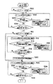
本発明の第1の実施の形態に係る画像読取装置の動作として、写真フィルム22に記録されたフィルム画像の読み取りを行う際に画像処理部16のオートセットアップエンジン144により実行される読取条件演算処理(図9)及び搬送制御部172により実行されるフィルム画像読取処理(図10)について説明する。尚、以下ではフィルム画像の読み取りを、フィルムキャリア38がセットされたエリアCCDスキャナ12で行う場合を例にとり説明する。また第1の実施の形態では読取対象となるフィルム画像が記録されている写真フィルム22はネガフィルムであるものとする。
【0071】
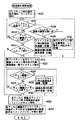
読取条件演算処理では、ステップ400において、フィルム画像に対してプレスキャンを行う際の所定の読取条件(エリアCCD42が飽和しないことを前提とする)をエリアCCDスキャナ12に対して通知すると共に、エリアCCDスキャナ12及び搬送制御部172に対し写真フィルム22に記録されたフィルム画像に対するプレスキャンの実行を指示する。次のステップ402ではプレスキャン画像データが入力されたか否か判定する。前記判定が否定された場合にはステップ404へ移行し、1本の写真フィルムに記録されている全てのフィルム画像のプレスキャン画像データが入力されたか否か判定する。この判定も否定された場合にはステップ402に戻り、ステップ402、404の判定を繰り返す。
【0072】
一方、フィルム画像読取処理では、ステップ500でプレスキャンの実行が指示されたか否か判定し、この判定が肯定されるまで待機する。プレスキャンの実行が指示されると、ステップ500の判定が肯定され、つぎのステップ502において、図12(A)及び(B)にも示すように、フィルムキャリア38は写真フィルム22を一定の搬送速度で所定方向(以下、往路方向という。)に搬送する。
【0073】
ステップ504では、エリアCCD42によるフィルム画像読取位置にフィルム画像が到達したか否か判定する。判定が否定された場合には、ステップ506で1本の写真フィルムに記録されている全てのフィルム画像の読み取りを行ったか否か判定する。この判定も否定された場合にはステップ502に戻り、ステップ502〜506を繰り返す。ステップ504の判定が肯定されると、ステップ508において、エリアCCDスキャナ12のエリアCCD42により、オートセットアップエンジン144から通知されたプレスキャン時の読取条件に従ってフィルム画像が読み取られ、読み取りによって得られた画像データがプレスキャン画像データとして画像処理部16に出力される。
【0074】
エリアCCD42によるフィルム画像読取位置にフィルム画像が到達する毎に、上記のステップ508が繰り返されることにより、フィルム画像が写真フィルムの往路方向先頭側から順に(往路方向先頭から順に1,2,…,nのコマ番号を各フィルム画像に付したとすると、コマ番号1,2,…,nの順に)読み取られ、読み取りによって得られた画像データがプレスキャン画像データとして画像処理部16に順に出力される。尚、このプレスキャンにおける読取条件としては、大多数のフィルム画像(濃度が所定範囲内のフィルム画像)を精度良く読み取ることができ、濃度が低いフィルム画像を読み取る場合にもエリアCCD42が飽和しないような標準的な読取条件が用いられる。
【0075】
読取条件演算処理(図9)では、プレスキャン画像データが入力されるとステップ402の判定が肯定されてステップ406へ移行し、入力されたプレスキャン画像データに基づき、該プレスキャン画像データが表すフィルム画像の濃度が高濃度か否か判定する。
【0076】
この判定は、例えば、フィルム画像の濃度値(例えば、最大濃度)について標準的な濃度の画像と濃度が極端に高い画像との境界に相当する閾値を設定しておき、プレスキャン画像データから求まる各フィルム画像の最大濃度値を閾値と比較することにより行うことができる。このステップ406は本発明の判定手段に対応している。
【0077】
ステップ406の判定が否定された場合には、入力されたプレスキャン画像データに対応するフィルム画像は、ステップ400で通知した標準的な読取条件で精度良く読み取れていると判断できるので、ステップ408に移行し、入力されたプレスキャン画像データに基づき、フィルム画像の平均濃度等の特徴量に基づいて同一のフィルム画像に対してファインスキャンを行う際の読取条件を演算し、コマ番号と対応させてRAM148等に記憶する。このステップ408は本発明の決定手段に対応している。
【0078】
次のステップ410では、入力されたプレスキャン画像データに基づいて、フィルム画像の撮影時の露出量、撮影光源種やその他の特徴量を求め、求めた特徴量に基づいて、同一のフィルム画像に対してファインスキャンを行うことで得られるファインスキャン画像データに対する画像処理の処理条件を演算する。また、順次入力されるプレスキャン画像データから求まる特徴量を順次、比較して類似のシーンを撮影したフィルム画像のデータか否かを判定し、類似のシーンを撮影したフィルム画像については同一又は近似した処理条件となるように処理条件を演算する。そして、処理条件を演算すると、演算した処理条件をコマ番号と対応させてRAM148に記憶した後にステップ402に戻る。
【0079】
一方、ステップ406の判定が肯定された場合には、入力されたフィルム画像の濃度が高く、先のステップ400で通知した標準的な読取条件では読み取りの精度が低いので、再プレスキャンが必要と判断できる。このため、第1の実施の形態ではステップ406の判定が肯定されると、該フィルム画像に対する再度のプレスキャンを精度良く行うために、ステップ412で再プレスキャン時に写真フィルム22(ネガフィルム)の透過光に対するエリアCCD42の受光量を増加することを読取条件に付加し、再プレスキャン時の読取条件をコマ番号と対応させて記憶させた後に、ステップ402に戻る。
【0080】
再プレスキャン時において写真フィルム22の透過光に対する受光光量を増加させるには、エリアCCDスキャナ12の絞り32の絞り量を最初のプレスキャン時より小さくするように絞り駆動モータ50を駆動制御するか、またはエリアCCDスキャナ12におけるエリアCCD42の各CCDセルの電荷蓄積時間を最初のプレスキャン時より増加させるようにマイクロプロセッサ46よりタイミングジェネレータ74に指令を出力することにより行われる。
【0081】
1本の写真フィルム22に記録されている全てのフィルム画像のプレスキャン画像データが入力され、入力された全てのプレスキャン画像データに対して上述の処理が行われると、ステップ404の判定が肯定されてステップ420へ移行し、1本の写真フィルム22の中に再プレスキャンが必要なフィルム画像が有ったか否かに基づいて、再プレスキャンが必要か否か判定する。
【0082】
判定が否定された場合にはステップ450に移行し、先に演算してRAM148に記憶した各フィルム画像に対するファインスキャン時の読取条件をエリアCCDスキャナ12に対して通知し、エリアCCDスキャナ12及び搬送制御部172に対し、ファインスキャンの実行を指示する。また、次のステップ452では、先に演算してRAM148に記憶した各フィルム画像のファインスキャン画像データに対する画像処理の処理条件をイメージプロセッサ部136のイメージプロセッサ140に通知する。
【0083】
一方、フィルム画像読み取り処理(図10)では、全てのフィルム画像の読み取りが終了するとステップ506の判定が肯定され、次のステップ510で再プレスキャンの実行が指示されたか否か判定するが、上記のようにファインスキャンの実行が指示された場合には、ステップ510の判定が否定され、ステップ530でフィルムキャリア38により、写真フィルム22を一定の搬送速度で所定方向と逆の方向(復路方向という。)に搬送する。
【0084】
次のステップ532ではエリアCCD42によるフィルム画像読取位置にフィルム画像が到達したか否か判定する。判定が否定された場合には、ステップ534で1本の写真フィルムに記録されている全てのフィルム画像の読み取りを行ったか否かを判定する。この判定も否定された場合にはステップ530に戻り、ステップ530〜534を繰り返す。ステップ532の判定が肯定されると、ステップ536でエリアCCD42により、オートセットアップエンジン144から通知されたファインスキャン時の読取条件に従ってフィルム画像が読み取られ、読み取りによって得られた画像データがファインスキャン画像データとして画像処理部16に出力される。
【0085】
したがって、再プレスキャンを行わない場合には、図12(A)に示すように、全てのフィルム画像に対するプレスキャンが完了すると直ちに、通知されたファインスキャン時の読取条件に従って、エリアCCD42により往路方向末尾側から順に(コマ番号n,n−1,…,1の順に)フィルム画像が読み取られ、得られた画像データがファインスキャン画像データとして画像処理部16に出力される。そして、エリアCCDスキャナ12から画像処理部16に入力された各フィルム画像のファインスキャン画像データは、イメージプロセッサ部136において、オートセットアップエンジン144で各フィルム画像毎に演算された処理条件に応じた画像処理が施されて出力される。
【0086】
一方、読取条件演算処理(図9)においてステップ420の判定が肯定された場合(再プレスキャンを行う場合)にはステップ422に移行し、再プレスキャンを行うフィルム画像のコマ番号及び読取条件(先のステップ412で記憶したコマ番号及び読取条件)をエリアCCDスキャナ12及び搬送制御部172に通知し、エリアCCDスキャナ12及び搬送制御部172に対し、通知したコマ番号に対応するフィルム画像に対する再プレスキャンの実行を指示する。すなわち、再プレスキャン時には最初のプレスキャン時より写真フィルム22のフィルム画像の透過光量に対するエリアCCD42の各CCDセルにおける受光量を増加させることを読取条件として追加し、該当するコマ番号のフィルム画像の再プレスキャンの実行を指示する。これによりフィルム画像読み取り処理(図10)では、ステップ510の判定が肯定されてステップ512へ移行し、写真フィルム22を復路方向に高速で搬送する。ステップ514では、エリアCCD42によるフィルム画像読取位置に、通知されたコマ番号に対応するフィルム画像が到達したか否か判定する。この判定が否定された場合にはステップ516に移行し、コマ番号が通知された全てのフィルム画像の読み取りが完了したか否か判定する。この判定も否定された場合にはステップ512に戻り、ステップ512〜516を繰り返す。
【0087】
ステップ514の判定が肯定されると 写真フィルム22の搬送速度を一定の搬送速度に変化させた後にステップ518に移行し、エリアCCD42より、オートセットアップエンジン144から通知された再プレスキャン時の読取条件に従って、すなわちエリアCCD42の各CCDセルの受光量を増加させた状態でフィルム画像が読み取られ、この読み取りにより得られた画像データが再プレスキャン画像データとして画像処理部16に出力される。この再プレスキャン時の読取条件は、写真フィルム22のフィルム画像の透過光量に対するエリアCCD42の各CCDセルの受光量を増加させる点以外は1回目のプレスキャンと同一の条件であるので、再プレスキャンを行うフィルム画像の濃度が高い場合にも、前記フィルム画像を精度良く読み取ることができる。
【0088】
ステップ518の処理を行うとステップ512に戻り、ステップ516の判定が肯定されるまで、ステップ512〜516を繰り返す。そしてステップ516の判定が肯定されると、ファインスキャンを行うためにステップ520で写真フィルム22を所定方向(往路方向)に再度搬送した後に、先に説明したステップ530へ移行する。
【0089】
したがって、第1の実施の形態において再プレスキャンが必要なフィルム画像が有った場合には、図12(B)に示すように、写真フィルム22を復路方向に搬送しながら、通知されたコマ番号に対応するフィルム画像(再プレスキャン実行対象のフィルム画像)についての再プレスキャンがエリアCCD42によって行われ、再プレスキャン実行対象の全てのフィルム画像に対する再プレスキャンが完了すると、写真フィルム22は往路方向に搬送される。
【0090】
読取条件演算処理(図9)では、再プレスキャンの実行を指示すると(ステップ422)、ステップ424へ移行し、再プレスキャン画像データが入力されたか否か判定する。前記判定が否定された場合にはステップ426へ移行し、先にコマ番号を通知した全てのフィルム画像の再プレスキャン画像データが入力されたか否か判定する。この判定も否定された場合にはステップ424に戻り、ステップ424、426の判定を繰り返す。
【0091】
再プレスキャン画像データが入力されると、ステップ424の判定が肯定されてステップ428へ移行し、入力された再プレスキャン画像データに基づき、同一のフィルム画像に対してファインスキャンを行う際の読取条件を演算し、コマ番号と対応させてRAM148等に記憶する。このステップ428も本発明の決定手段に対応している。前述のように、再プレスキャンではフィルム画像の透過光量に対するエリアCCD42の各CCDセルの受光量を増加させることによりフィルム画像の濃度が高い場合にも精度良く読み取ることができる読取条件が得られる。
【0092】
次のステップ430では、入力された再プレスキャン画像データに基づいて、同一のフィルム画像に対してファインスキャンを行うことで得られるファインスキャン画像データに対する画像処理の処理条件を演算し、演算した処理条件をコマ番号と対応させてRAM148に記憶した後にステップ424に戻る。
【0093】
そして全てのフィルム画像の再プレスキャン画像データが入力され、入力された全ての再プレスキャン画像データに対してステップ428、430の処理が行われると、ステップ426の判定が肯定されてステップ450へ移行し、前述のように各フィルム画像に対するファインスキャンが行われる。なお、ステップ400、412、420、422、450は本発明の制御手段に対応している。
【0094】
なお、第1の実施の形態では再プレスキャンの実行が指示された場合に、写真フィルム22を復路方向に搬送しながら再プレスキャンを行い、指示されたフィルム画像に対する再プレスキャンを完了すると、写真フィルム22を一旦、往路方向に搬送した後に、復路方向に搬送しながら各フィルム画像に対するファインスキャンを行うようにしていたが、再プレスキャン、ファインスキャン時の写真フィルム22の搬送シーケンスは、これに限定されることなく、例えば、復路で再プレスキャンを行い次の往路でファインスキャンを行う、復路でファインスキャンと再プレスキャンを行う等の種々の方式が考えられるが、この内容は本発明の本旨ではないので、説明を省略する。
【0095】
本発明の第1の実施の形態に係る画像読取装置によれば、判定手段によりプレスキャンの結果からプレスキャンを再度行う必要があると判定された濃度の高いフィルム画像について同一条件で再度、プレスキャンをフィルム画像の透過光量に対するエリアCCD42の各CCDセルの受光量を増加させて行われるので、濃度の高いフィルム画像を精度良く読み取ることができる。
【0096】
次に本発明の第2の実施の形態に係る画像読取装置について説明する。なお、第2の実施の形態に係る画像読取装置は、図1乃至図8に示した第1の実施の形態に係る画像読取装置と同一構成であるので、各構成要素に同一符号を付し、画像読取装置の構成の説明を省略する。
【0097】
第2の実施の形態に係る画像読取装置の動作として、搬送制御部172で実行されるフィルム画像読み取り処理(図10)及び画像処理部16のオートセットアップエンジン144で実行される読取条件演算処理(図11)について第1の実施の形態と異なる部分について説明する。なお、図11の読取条件演算処理において図9と同一の判断ステップ、処理ステップについては同一の符号を付してある。搬送制御部172で実行されるフィルム画像読み取り処理(図10)は第1の実施の形態と同じであるのでその説明を省略する。また第2の実施の形態では読取対象となる写真フィルム22はリバーサルフィルムであるものとする。
【0098】
図11において、第2の実施の形態に係る読取条件演算処理では、入力されたプレスキャン画像データが表すフィルム画像の濃度が高濃度である場合、すなわちリバーサルフィルムで露光量が不足している場合(ステップ406の判定が肯定された場合)にはステップ600に移行する。ステップ600ではキーボード166により濃度補正が指示されたか否かが判定される。すなわち、プレスキャンされたフィルム画像の各コマ番号に対応してキーボード166による濃度補正の指示の有無を示すデータと、キーボード166によりフィルム画像について濃度補正の指示がなされた際にはその濃度補正量を示すデータとがメモリ162に格納されるが、ステップ600の判定は、オートセットアップエンジン144がプレスキャンされたフィルム画像のコマ番号に対応してメモリ162に格納された濃度補正の指示の有無を示すデータの記憶内容を参照して行われる。
【0099】
ステップ600で判定が肯定された場合、すなわちプレスキャンされた高濃度のフィルム画像について濃度補正の指示が有った場合にはステップ602に移行し、濃度補正の指示が有ったフィルム画像の濃度補正量が大きいか否か、すなわち濃度補正量が予め設定された所定値以上か否かが判定される。この判定はオートセットアップエンジン144がプレスキャンされたフィルム画像のコマ番号に対応してメモリ162に格納された濃度補正量を示すデータの記憶内容を参照して行われる。
【0100】
ステップ600、602は写真フィルム(リバーサルフィルム)22において高濃度の各フィルム画像について撮影者の撮影意図(意図的にフィルム画像を高濃度にしているのか否か)を反映させるためである。したがって、ステップ602の判定が肯定された場合、すなわちプレスキャンされた高濃度のフィルム画像のうち濃度補正の指示が有り、かつ濃度補正量が所定値以上であると判定された場合には撮影者が意図的にフィルム画像の濃度が高くなるような撮影条件で撮影したものではなく、先のステップ400で通知した標準的な読取条件では読み取りの精度が低いので、再プレスキャンが必要と判断することができる。
【0101】
このため、ステップ602の判定が肯定されると、該フィルム画像に対する再度のプレスキャンを精度良く行うために、ステップ412で再プレスキャン時に写真フィルム(リバーサルフィルム)22の透過光量に対するエリアCCD42の各CCDセルの受光量を増加することを読取条件に付加し、再プレスキャン時の読取条件をコマ番号と対応させて記憶させた後に、ステップ402に戻る。
【0102】
尚、ステップ406、600、602は判定手段に対応している。
再プレスキャン時において写真フィルム22の透過光に対する受光量を増加させるのに、エリアCCDスキャナ12の絞り32の絞り量を最初のプレスキャン時より小さくするように絞り駆動モータ50を駆動制御するか、またはエリアCCDスキャナ12におけるエリアCCD42の各CCDセルの電荷蓄積時間を最初のプレスキャン時より増加させるようにマイクロプロセッサ46よりタイミングジェネレータ74に指令を出力することにより行われるのは第1の実施の形態と同様である。
【0103】
一方、ステップ406の判定が否定された場合、すなわちプレスキャンされたフィルム画像の濃度が高くないと判定された場合には、入力されたプレスキャン画像データに対応するフィルム画像は、ステップ400で通知した標準的な読取条件で精度良く読み取れていると判断できるので、ステップ408に移行し、入力されたプレスキャン画像データに基づき、フィルム画像の平均濃度等の特徴量に基づいて同一のフィルム画像に対してファインスキャンを行う際の読取条件を演算し、コマ番号と対応させてRAM148等に記憶する。
【0104】
次のステップ410では、入力されたプレスキャン画像データに基づいて、フィルム画像の撮影時の露出量、撮影光源種やその他の特徴量を求め、求めた特徴量に基づいて、同一のフィルム画像に対してファインスキャンを行うことで得られるファインスキャン画像データに対する画像処理の処理条件を演算する。また、順次入力されるプレスキャン画像データから求まる特徴量を順次、比較して類似のシーンを撮影したフィルム画像のデータか否かを判定し、類似のシーンを撮影したフィルム画像については同一又は近似した処理条件となるように処理条件を演算する。そして、処理条件を演算すると、演算した処理条件をコマ番号と対応させてRAM148に記憶した後にステップ402に戻る。
【0105】
またステップ600、602の判定が否定された場合、すなわちプレスキャンされた高濃度のフィルム画像のうち濃度補正の指示がなされなかったか、または濃度補正の指示がキーボード166によりなされ、かつその濃度補正量が小さいと判定された場合には、撮影者が意図的にフィルム画像の濃度を高くする撮影条件で撮影したものと判断できる。そこでこの場合にもステップ408に移行し、既述したようにファインスキャン時の読取条件の演算すると共に、演算した読取条件はフィルム画像のコマ番号と対応させてRAM148等に記憶する。
【0106】
更にステップ410では、既述したように入力されたプレスキャン画像データに基づいて、フィルム画像の撮影時の露光量、撮影光源種やその他の特徴量を求め、求めた特徴量に基づいて同一のフィルム画像に対してファインスキャンを行うことにより得られるファインスキャン画像データに対する画像処理の処理条件を演算する。そして演算した処理条件をコマ番号と対応させてRAM148に記憶した後にステップ402に戻る。
【0107】
第2の実施の形態に係る画像読取装置によれば、判定手段によりプレスキャンの結果からプレスキャンを再度行う必要があると判定された濃度の高いフィルム画像のうち指示手段(キーボード166)により指示された濃度補正量が大きいフィルム画像について最初に行われたプレスキャンと同一条件で再度、プレスキャンをエリアCCD42の各CCDセルの受光量を増加させて行われるので、撮影者の意図を反映した上でリバーサルフィルムに記録された濃度の高いフィルム画像を精度良く読み取ることができる。
【0108】
なお、第1、第2の実施の形態に係る画像読取装置ではフィルム画像の読み取りにエリアCCDスキャナ12で行う場合について述べたが、ラインCCDスキャナ14でフィルム画像を読み取る場合も同様であるので説明を省略する。
【0109】
また上記ではフィルム画像の読み取りを行うスキャナとして、読取対象の写真フィルムのサイズが異なるエリアCCDスキャナ12及びラインCCDスキャナ14を設けていたが、これに代えて、各種サイズの写真フィルムのフィルム画像を全て読み取り可能なスキャナ(ラインスキャナが好適である)を設けてもよい。
【0110】
【発明の効果】
請求項1に記載の発明によれば、予備読み取りを再度行う必要があると判定された画像が有った場合には、この画像に対する予備読み取りを読取手段の受光量を増加させて再度行わせた後に、該再度の予備読み取りの結果から決定手段によって決定された読取条件で前記画像の本読み取りを行わせるようにしたので、予備読み取りの読取条件では精度良く読み取ることが困難な画像についても再度の予備読み取りで読取条件を変えることなくSN比の高い状態で前記画像の読み取りを行うことができ、それ故プレスキャンで読み取った画像データに基づいてファインスキャン時の読取条件及びファインスキャンにより得られた画像データの画像処理条件を決定するためのセットアップ演算の精度の向上が図れ、高濃度の画像を精度良く読み取ることができる。
【0111】
請求項2に記載の発明によれば、判定手段により予備読み取りの結果からた濃度の高いと判定されたネガフィルムのフィルム画像について制御手段により同一条件で再度、予備読み取りを前記読取手段の受光量を増加させて行われるので、濃度の高いネガフィルムのフィルム画像を精度良く読み取ることができる。
【0112】
請求項3に記載の発明によれば、判定手段により前記指示手段により濃度補正の指示が有り、かつ指示された濃度補正量が大きく、かつフィルム画像の濃度が高い場合に最初に行われた予備読み取りと同一条件で再度、予備読み取りを前記読取手段の受光量を増加させて行われるので、撮影者の意図を反映した上でリバーサルフィルムに記録された濃度の高いフィルム画像を精度良く読み取ることができる。
【図面の簡単な説明】
【図1】本発明の第1の実施の形態に係る画像読取装置の概略構成を示すブロック図。
【図2】図1におけるエリアCCDスキャナの光学系の概略構成図。
【図3】図1におけるエリアCCDスキャナの電気系の構成を示すブロック図。
【図4】図1におけるラインCCDスキャナの光学系の概略構成図。
【図5】図1における画像処理部の構成を示すブロック図である。
【図6】図1におけるレーザプリンタ部の露光部の光学系の概略構成図である。
【図7】図1におけるレーザプリンタ部及びプロセッサ部の電気系の構成を示すブロック図。
【図8】図5におけるフィルムキャリアの概略構成図。
【図9】本発明の第1の実施の形態に係る画像読取装置による読取条件演算処理の内容を示すフローチャート。
【図10】本発明の第1の実施の形態に係る画像読取装置によるフィルム画像読み取り処理の内容を示すフローチャート。
【図11】本発明の第2の実施の形態に係る画像読取装置による読取条件演算処理の内容を示すフローチャート。
【図12】(A)は再プレスキャン要のコマが無い場合、(B)は再プレスキャン要のコマが有る場合の写真フィルムの搬送及びフィルム画像の読み取りのシーケンスの一例を各々、示すタイミングチャート。
【図13】本発明の実施の形態に係る画像読取装置の外観構成を示す斜視図。
【符号の説明】
10 ディジタルラボシステム
12 エリアCCDスキャナ
14 ラインCCDスキャナ
16 画像処理部
18 レーザプリンタ部
20 プロセッサ部
22 写真フィルム
26 入力部
28 出力部
38 フィルムキャリア
42 エリアCCD
144 オートセットアップエンジン
172 搬送制御部[0001]
BACKGROUND OF THE INVENTION
The present invention relates to an image reading apparatus, and in particular, performs preliminary reading on an image, determines a reading condition when performing the main reading of the image based on a result of the preliminary reading, and reads the image under the reading condition. The present invention relates to an image reading apparatus that performs main reading.
[0002]
[Prior art]
Conventionally, after a film image recorded on a photographic film is read by an image reading apparatus equipped with a reading sensor such as a CCD, image processing such as various corrections is performed on the image data obtained by the reading. An image processing system for recording an image on a recording material or displaying an image on a display is known.
[0003]
Film images (especially negative images recorded on negative films) have various density images ranging from images with wide latitude and low density to images with high density, so that recorded images and display images with desired image quality can be obtained. Therefore, the image reading apparatus preliminarily reads a film image (so-called prescan), and reading conditions according to the density of the film image (for example, the amount of light applied to the film image, the charge accumulation time of the CCD, etc.) The film image was read under the determined reading conditions (so-called fine scan).
[0004]
[Problems to be solved by the invention]
Usually, in pre-scanning, an image reading device quickly and roughly reads an image on a film, and determines reading conditions (exposure amount, filter insertion amount, etc.) and image processing conditions during fine scanning based on the read image data. Perform setup calculations. In pre-scanning, a film image is always read under a certain reading condition (exposure amount, filter insertion amount), but the amount of light irradiated to the film image at this time is such that the output of the reading sensor does not saturate even when reading a low-density film. Is set to the amount of light. In this case, if a high-density film such as an overexposed negative film (overnegative film) or underexposed reversal film (underreversal film) is read by prescanning, the amount of light received by the reading sensor decreases, and the SN ratio is reduced. There was a problem that only bad image data could be taken in, and the error of the setup calculation became large.
[0005]
On the other hand, there are many photographers who use reversal film, such as professional photographers and semi-professionals who have clear shooting intentions. Conversely, even if the bright part is crushed, the dark part is emphasized and expressed. The reversal film has a characteristic that the reproduction range of the film is wide.
[0006]
The present invention has been made in view of such circumstances, and is for determining reading conditions at the time of fine scanning and image processing conditions of image data obtained by fine scanning based on image data read by pre-scanning. An object of the present invention is to provide an image reading apparatus capable of improving the accuracy of the setup calculation and reading a high density image with high accuracy.
[0007]
[Means for Solving the Problems]
In order to achieve the above object, according to the first aspect of the present invention, there is provided reading means for irradiating a document with light and reading an image based on the amount of received light, and the reading means performs preliminary reading of the image. A determination unit that determines a reading condition when performing the main reading of the image based on a result, and a determination unit that determines whether the film image has a high density based on a result of the image reading performed by the reading unit. The image is preliminarily read by the reading means, the image can be read under the reading conditions determined by the determining means from the result of the preliminary reading, and the film image has a high density by the determining means. If it is determined that the pre-reading for the film image having a high density is performed again by increasing the amount of light received by the reading unit, the preliminary reading is performed again. And having a control means for causing the main reading of the image reading condition determined by said determining means from the fruit.
[0008]
In the image reading apparatus having the above-described configuration, the determining unit determines the reading condition for performing the main reading of the image based on the result of the reading of the image by the reading unit, and the determining unit is configured to perform the preliminary reading of the image by the reading unit. It is determined whether or not the film image has a high density based on the result. The control unit causes the reading unit to perform preliminary reading of the image, and can perform the main reading of the image under the reading condition determined by the determination unit from the result of the preliminary reading. If it is determined that there is, the preliminary reading for the film image having a high density is performed again by increasing the amount of light received by the reading unit, and then determined by the determination unit from the result of the preliminary scanning again. The image is actually read under the reading conditions.
[0009]
According to the first aspect of the present invention, when there is an image determined that it is necessary to perform preliminary reading again, the preliminary reading for the image is performed again by increasing the amount of light received by the reading unit. After that, since the image is actually read under the reading condition determined by the determining means from the result of the preliminary reading again, an image that is difficult to read accurately under the reading condition of the preliminary reading is again displayed. The image can be read with a high S / N ratio in the preliminary reading of the image, and therefore, the reading conditions at the time of fine scanning based on the image data read by the pre-scan and the image processing of the image data obtained by the fine scanning The accuracy of the setup calculation for determining the conditions can be improved, and a high-density image can be read with high accuracy.
[0010]
According to a second aspect of the present invention, in the image reading apparatus according to the first aspect, the image is a plurality of film images recorded on a negative film.
[0011]
In the image reading apparatus configured as described above, the image to be read is a plurality of film images recorded on a long negative film, and the control means is based on the result of preliminary reading of the film image performed by the reading means. Then, preliminary reading of the film image determined to be a film image having a high density by the determination unit is performed again by increasing the amount of light received by the reading unit.
[0012]
According to the second aspect of the present invention, the pre-reading is again performed under the same conditions by the control unit for the film image of the negative film determined to have a high density from the result of the pre-reading by the determining unit, and the received light amount of the reading unit. Therefore, a film image of a negative film having a high density can be read with high accuracy.
[0013]
Further, the invention according to claim 3 is the image reading apparatus according to claim 1, wherein the plurality of images are film images recorded on a reversal film, and further includes an instruction means for instructing density correction of the film image. And the determination means determines that it is necessary to perform preliminary reading again when there is an instruction for density correction by the instruction means, the specified density correction amount is large, and the density of the film image is high. It is characterized by.
[0014]
In the image reading apparatus having the above-described configuration, it is possible to instruct density correction for a reversal film film image having a high density by an instruction unit such as a keyboard while displaying and monitoring the result of preliminary reading of the film image by the reading unit. Is possible.
[0015]
The determination unit determines that the preliminary reading needs to be performed again when there is an instruction for density correction by the instruction unit, the specified density correction amount is large, and the density of the film image is high.
[0016]
According to the third aspect of the present invention, the preliminary reading is performed again when there is an instruction for density correction by the instruction means by the determination means, the specified density correction amount is large, and the density of the film image is high. Since it is performed by increasing the amount of light received by the reading means, it is possible to accurately read a film image having a high density recorded on the reversal film while reflecting the intention of the photographer.
[0017]
DETAILED DESCRIPTION OF THE INVENTION
Hereinafter, embodiments of the present invention will be described in detail with reference to the drawings. In the following, a digital laboratory system will be described as an example of an image reading apparatus according to the first embodiment of the present invention.
[0018]
(Schematic configuration of the entire system)
FIG. 1 shows a digital laboratory system 10 according to the present embodiment. As shown in FIG. 13, the lab system 10 includes an
[0019]
The
[0020]
The
[0021]
The
[0022]
The
[0023]
The
[0024]
(Configuration of area CCD scanner)
Next, the configuration of the
[0025]
The
[0026]
On the opposite side of the
[0027]
The
[0028]
FIG. 3 shows a schematic configuration of the electrical system of the
[0029]
The
[0030]
In addition,
[0031]
The
[0032]
On the other hand, the
[0033]
The
[0034]
The signal output terminal of the
[0035]
The
[0036]
(Configuration of line CCD scanner)
Next, the configuration of the
[0037]
FIG. 4 shows a schematic configuration of the optical system of the
[0038]
Although the illustration of the electrical system configuration of the
[0039]
(Configuration of image processing unit)
Next, the configuration of the
[0040]
The area
[0041]
Further, the photoelectric conversion characteristics of the
[0042]
On the other hand, in the image data of the film image for adjustment, if the density of a specific pixel is significantly different from the density of other pixels, there is some abnormality in the CCD cell corresponding to the specific pixel, and the specific These pixels can be determined as defective pixels. The defective
[0043]
The line
[0044]
The output terminals of the area
[0045]
The
[0046]
The image processor 140 captures image data stored in the frame memory 142, performs gradation conversion, color conversion, hypertone processing for compressing the gradation of the ultra-low frequency brightness component of the image, and enhances sharpness while suppressing grain. Various image processing such as hyper sharpness processing is performed. The processing conditions for the image processing are automatically calculated by an auto setup engine 144 (described later), and image processing is performed according to the calculated processing conditions. The image processor 140 is connected to the input /
[0047]
By the way, in this embodiment, each film image is basically read twice by the
[0048]
The auto setup engine 144 includes a CPU 146, a RAM 148 (for example, DRAM), a ROM 150 (for example, a ROM whose contents can be rewritten), and an input /
[0049]
The auto setup engine 144 notifies the
[0050]
The optimum processing conditions for image processing also vary depending on whether the image data after image processing is used for recording an image on photographic paper in the
[0051]
Further, the auto setup engine 144 is for image recording that defines a gray balance or the like when recording an image on photographic paper by the
[0052]
The input /
[0053]
The
[0054]
Also, a driver (not shown) for reading / writing data from / to a storage medium such as a memory card and a communication control device for communicating with other information processing devices are connected via a
[0055]
The
[0056]
As will be described later, in the second embodiment of the present invention, the
[0057]
(Configuration of laser printer unit and processor unit)
Next, the configuration of the
[0058]
A
[0059]
A
[0060]
FIG. 7 shows a schematic configuration of the electrical system of the
[0061]
The
[0062]
When recording an image on the
[0063]
The
[0064]
Then, as the
[0065]
A
[0066]
The printer control circuit 238 also includes a magazine sensor 250 that detects the size of the photographic paper stored in the magazine, and a magazine sensor 250 that stores unexposed
[0067]
The processor unit control circuit 256 detects the passage of the
[0068]
Further, the processor unit control circuit 256 includes a
[0069]
(Structure of film carrier)
Next, the configuration of the
The
[0070]
As an operation of the image reading apparatus according to the first embodiment of the present invention, a reading condition calculation process executed by the auto setup engine 144 of the
[0071]
In the reading condition calculation process, in
[0072]
On the other hand, in the film image reading process, it is determined in
[0073]
In
[0074]
Each time the film image reaches the film image reading position by the
[0075]
In the reading condition calculation process (FIG. 9), when pre-scan image data is input, the determination in
[0076]
This determination is obtained from prescanned image data by setting a threshold value corresponding to a boundary between a standard density image and an extremely high density image for the density value (for example, maximum density) of the film image, for example. This can be done by comparing the maximum density value of each film image with a threshold value. This
[0077]
If the determination in
[0078]
In the
[0079]
On the other hand, if the determination in
[0080]
In order to increase the amount of light received with respect to the transmitted light of the
[0081]
If prescan image data of all film images recorded on one
[0082]
If the determination is negative, the process proceeds to step 450, where the
[0083]
On the other hand, in the film image reading process (FIG. 10), when all the film images have been read, the determination in
[0084]
In the
[0085]
Therefore, when the re-pre-scan is not performed, as shown in FIG. 12A, immediately after the pre-scan for all the film images is completed, the
[0086]
On the other hand, when the determination in
[0087]
If the determination in
[0088]
If the process of
[0089]
Therefore, when there is a film image that needs to be re-pre-scanned in the first embodiment, the notified frame is conveyed while transporting the
[0090]
In the reading condition calculation process (FIG. 9), when execution of re-prescan is instructed (step 422), the process proceeds to step 424, and it is determined whether or not re-prescan image data is input. If the determination is negative, the process proceeds to step 426, and it is determined whether or not re-prescan image data of all the film images for which the frame numbers have been previously notified have been input. If this determination is also negative, the process returns to step 424 and the determinations of
[0091]
When the re-prescan image data is input, the determination in
[0092]
In the
[0093]
When the re-prescan image data of all the film images is input and the processing of
[0094]
In the first embodiment, when execution of re-prescan is instructed, re-pre-scan is performed while transporting the
[0095]
According to the image reading apparatus according to the first embodiment of the present invention, a high-density film image determined to need to be pre-scanned again from the result of the pre-scan by the determination unit is pressed again under the same conditions. Since the can is performed by increasing the amount of light received by each CCD cell of the
[0096]
Next, an image reading apparatus according to a second embodiment of the present invention will be described. The image reading apparatus according to the second embodiment has the same configuration as that of the image reading apparatus according to the first embodiment shown in FIGS. Description of the configuration of the image reading apparatus is omitted.
[0097]
As an operation of the image reading apparatus according to the second embodiment, a film image reading process (FIG. 10) executed by the
[0098]
In FIG. 11, in the reading condition calculation processing according to the second embodiment, when the density of the film image represented by the input prescan image data is high, that is, when the exposure amount is insufficient in the reversal film. If the determination in
[0099]
If the determination in
[0100]
[0101]
For this reason, if the determination in
[0102]
Whether the
[0103]
On the other hand, if the determination in
[0104]
In the
[0105]
If the determinations in
[0106]
Further, in
[0107]
According to the image reading apparatus according to the second embodiment, the instruction unit (keyboard 166) indicates the high-density film image determined to need to be pre-scanned again from the result of the pre-scan by the determination unit. Since the pre-scan is performed again by increasing the received light amount of each CCD cell of the
[0108]
In the image reading apparatus according to the first and second embodiments, the case where the film image is read by the
[0109]
In the above description, the
[0110]
【The invention's effect】
According to the first aspect of the present invention, when there is an image determined that it is necessary to perform preliminary reading again, the preliminary reading for the image is performed again by increasing the amount of light received by the reading unit. After that, the image is actually read under the reading condition determined by the determining means from the result of the preliminary reading again. In the preliminary reading, the image can be read with a high S / N ratio without changing the reading condition. Therefore, the image can be obtained by the reading condition in fine scanning and the fine scanning based on the image data read in the pre-scanning. The accuracy of the setup calculation for determining the image processing conditions of the captured image data can be improved, and high-density images can be read accurately. It is possible.
[0111]
According to the second aspect of the present invention, the pre-reading is again performed under the same conditions by the control unit for the film image of the negative film determined to have a high density from the result of the pre-reading by the determining unit, and the received light amount of the reading unit. Therefore, a film image of a negative film having a high density can be read with high accuracy.
[0112]
According to the third aspect of the present invention, the preliminary operation performed first when there is an instruction for density correction by the instruction means by the determination means, the specified density correction amount is large, and the density of the film image is high. Since the preliminary reading is performed again by increasing the amount of light received by the reading means under the same conditions as the reading, it is possible to accurately read a high-density film image recorded on the reversal film while reflecting the photographer's intention. it can.
[Brief description of the drawings]
FIG. 1 is a block diagram showing a schematic configuration of an image reading apparatus according to a first embodiment of the present invention.
2 is a schematic configuration diagram of an optical system of the area CCD scanner in FIG. 1. FIG.
3 is a block diagram showing a configuration of an electrical system of the area CCD scanner in FIG. 1. FIG.
4 is a schematic configuration diagram of an optical system of the line CCD scanner in FIG. 1. FIG.
5 is a block diagram illustrating a configuration of an image processing unit in FIG. 1. FIG.
6 is a schematic configuration diagram of an optical system of an exposure unit of the laser printer unit in FIG. 1. FIG.
7 is a block diagram showing a configuration of an electrical system of a laser printer unit and a processor unit in FIG. 1. FIG.
8 is a schematic configuration diagram of the film carrier in FIG.
FIG. 9 is a flowchart showing the contents of reading condition calculation processing by the image reading apparatus according to the first embodiment of the present invention.
FIG. 10 is a flowchart showing the contents of a film image reading process by the image reading apparatus according to the first embodiment of the invention.
FIG. 11 is a flowchart showing the contents of reading condition calculation processing by the image reading apparatus according to the second embodiment of the present invention.
12A is a timing chart showing an example of a photographic film transport sequence and a film image reading sequence when there is no frame that requires re-prescanning, and FIG. chart.
FIG. 13 is a perspective view showing an external configuration of the image reading apparatus according to the embodiment of the present invention.
[Explanation of symbols]
10 Digital Lab System
12 area CCD scanner
14 line CCD scanner
16 Image processing unit
18 Laser printer
20 Processor section
22 Photo film
26 Input section
28 Output section
38 film carrier
42 area CCD
144 Auto setup engine
172 Transport control unit
Claims (3)
該読取手段が画像の予備読み取りを行った結果に基づいて前記画像の本読み取りを行う際の読取条件を決定する決定手段と、
前記読取手段が画像の予備読み取りを行った結果に基づいて濃度が高いフィルム画像か否かを判定する判定手段と、
前記読取手段により画像の予備読み取りを行わせ、該予備読み取りの結果から前記決定手段によって決定された読取条件で画像の本読み取りを行せると共に、前記判定手段により濃度が高いフィルム画像であると判定された場合には、前記濃度が高いフィルム画像に対する予備読み取りを前記読取手段の受光量を増加させて再度行わせた後に、該再度の予備読み取りの結果から前記決定手段によって決定された読取条件で前記画像の本読み取りを行わせる制御手段と、
を有することを特徴とする画像読取装置。Reading means for irradiating a document with light and reading an image based on the amount of transmitted light received;
Determining means for determining a reading condition when performing the main reading of the image based on a result of the image reading performed by the reading means;
A determination unit for determining whether the image is a film image having a high density based on a result of the image reading performed by the reading unit;
The image is preliminarily read by the reading means, and the image can be read with the reading conditions determined by the determining means based on the result of the preliminary reading. In such a case, after the preliminary reading of the film image having a high density is performed again by increasing the amount of light received by the reading unit, the reading condition determined by the determining unit is determined from the result of the preliminary scanning again. Control means for performing the main reading of the image;
An image reading apparatus comprising:
フィルム画像の濃度補正を指示する指示手段を更に有し、
前記判定手段は、前記指示手段により濃度補正の指示が有り、かつ指示された濃度補正量が大きく、かつフィルム画像の濃度が高い場合に予備読み取りを再度行う必要があると判定することを特徴とする請求項1に記載の画像読取装置。The plurality of images are film images recorded on a reversal film,
An instruction means for instructing density correction of the film image;
The determination means determines that it is necessary to perform preliminary reading again when there is an instruction for density correction by the instruction means, the specified density correction amount is large, and the density of the film image is high. The image reading apparatus according to claim 1.
Priority Applications (1)
| Application Number | Priority Date | Filing Date | Title |
|---|---|---|---|
| JP17865097A JP3607046B2 (en) | 1997-07-03 | 1997-07-03 | Image reading device |
Applications Claiming Priority (1)
| Application Number | Priority Date | Filing Date | Title |
|---|---|---|---|
| JP17865097A JP3607046B2 (en) | 1997-07-03 | 1997-07-03 | Image reading device |
Publications (2)
| Publication Number | Publication Date |
|---|---|
| JPH1127465A JPH1127465A (en) | 1999-01-29 |
| JP3607046B2 true JP3607046B2 (en) | 2005-01-05 |
Family
ID=16052181
Family Applications (1)
| Application Number | Title | Priority Date | Filing Date |
|---|---|---|---|
| JP17865097A Expired - Fee Related JP3607046B2 (en) | 1997-07-03 | 1997-07-03 | Image reading device |
Country Status (1)
| Country | Link |
|---|---|
| JP (1) | JP3607046B2 (en) |
-
1997
- 1997-07-03 JP JP17865097A patent/JP3607046B2/en not_active Expired - Fee Related
Also Published As
| Publication number | Publication date |
|---|---|
| JPH1127465A (en) | 1999-01-29 |
Similar Documents
| Publication | Publication Date | Title |
|---|---|---|
| JP3618521B2 (en) | Image exposure device | |
| US6366366B1 (en) | Image reading method and apparatus | |
| US6538717B2 (en) | Method of image reading by one time to-and-fro scanning | |
| JP3453506B2 (en) | Image reading device | |
| US6757083B1 (en) | Image input apparatus | |
| JPH11146187A (en) | Image composite device and image composite method | |
| JP3607046B2 (en) | Image reading device | |
| JP3670447B2 (en) | Image output apparatus and image output method | |
| JP3688857B2 (en) | Image reading device | |
| JP3784924B2 (en) | Image reading apparatus and method | |
| JPH1132218A (en) | Device and method for correcting defective pixel | |
| JPH1127523A (en) | Defective pixel correction apparatus and defective pixel correcting method | |
| JPH1198315A (en) | Picture reading device | |
| JP2000155280A (en) | Scanning optical system | |
| JPH11195047A (en) | Picture processor | |
| JP3813713B2 (en) | Image processing device | |
| JPH1184293A (en) | Scanning optical system | |
| JP3709268B2 (en) | Image reading device | |
| JPH1132140A (en) | Image processor | |
| JPH1184284A (en) | Scanning optical system | |
| JPH1132168A (en) | Original reader | |
| JP2000125084A (en) | Document reader | |
| JPH11225256A (en) | Image processing unit | |
| JP4002329B2 (en) | Image reading device | |
| JPH11112734A (en) | Picture reader and picture processor |
Legal Events
| Date | Code | Title | Description |
|---|---|---|---|
| A977 | Report on retrieval |
Free format text: JAPANESE INTERMEDIATE CODE: A971007 Effective date: 20040927 |
|
| TRDD | Decision of grant or rejection written | ||
| A01 | Written decision to grant a patent or to grant a registration (utility model) |
Free format text: JAPANESE INTERMEDIATE CODE: A01 Effective date: 20041005 |
|
| A61 | First payment of annual fees (during grant procedure) |
Free format text: JAPANESE INTERMEDIATE CODE: A61 Effective date: 20041006 |
|
| R150 | Certificate of patent or registration of utility model |
Free format text: JAPANESE INTERMEDIATE CODE: R150 |
|
| FPAY | Renewal fee payment (event date is renewal date of database) |
Free format text: PAYMENT UNTIL: 20071015 Year of fee payment: 3 |
|
| FPAY | Renewal fee payment (event date is renewal date of database) |
Free format text: PAYMENT UNTIL: 20081015 Year of fee payment: 4 |
|
| LAPS | Cancellation because of no payment of annual fees |