JP3605897B2 - Irradiation method using laser beam irradiation torch - Google Patents
Irradiation method using laser beam irradiation torch Download PDFInfo
- Publication number
- JP3605897B2 JP3605897B2 JP23825695A JP23825695A JP3605897B2 JP 3605897 B2 JP3605897 B2 JP 3605897B2 JP 23825695 A JP23825695 A JP 23825695A JP 23825695 A JP23825695 A JP 23825695A JP 3605897 B2 JP3605897 B2 JP 3605897B2
- Authority
- JP
- Japan
- Prior art keywords
- laser beam
- irradiation
- convex lens
- torch
- fiber cable
- Prior art date
- Legal status (The legal status is an assumption and is not a legal conclusion. Google has not performed a legal analysis and makes no representation as to the accuracy of the status listed.)
- Expired - Lifetime
Links
Images


Classifications
-
- Y—GENERAL TAGGING OF NEW TECHNOLOGICAL DEVELOPMENTS; GENERAL TAGGING OF CROSS-SECTIONAL TECHNOLOGIES SPANNING OVER SEVERAL SECTIONS OF THE IPC; TECHNICAL SUBJECTS COVERED BY FORMER USPC CROSS-REFERENCE ART COLLECTIONS [XRACs] AND DIGESTS
- Y02—TECHNOLOGIES OR APPLICATIONS FOR MITIGATION OR ADAPTATION AGAINST CLIMATE CHANGE
- Y02E—REDUCTION OF GREENHOUSE GAS [GHG] EMISSIONS, RELATED TO ENERGY GENERATION, TRANSMISSION OR DISTRIBUTION
- Y02E30/00—Energy generation of nuclear origin
- Y02E30/30—Nuclear fission reactors
Description
【0001】
【発明の属する技術分野】
本発明は、例えば、原子炉圧力容器に貫通して取り付けられるインコアモニタハウジングなどの小口径管の内壁に所定の範囲でクラッド部などの補強皮膜を形成するために用いられるレーザビーム照射トーチを用いた照射方法に関するものである。
【0002】
【従来の技術】
一般に、原子炉設備の中核を成す原子炉圧力容器には、図4に示すように、その下鏡部aに貫通孔bを形成し、その貫通孔bにインコアモニタハウジング等の小口径管cが貫通して溶接されている。さらに、比較的初期に建設されたプラントではこの小口径管cの内壁には、溶接部d周縁領域の亀裂などを防止すべく、その領域の強度を補強するために合金化したクラッド部eを施工する場合がある。
【0003】
このクラッド部eの形成方法としては、先ず、図5に示すように、小口径管c内に、例えば、Cr:4、Ni:4、Mo:0.5、Fe:1の配合割合の混合金属粉末からなるペースト状のクラッド材を約0.3〜0.4mm厚に塗布した後、図4に示すように、その小口径管c内にレーザビーム照射トーチfを挿入し、その後、このレーザビーム照射トーチfを旋回手段gによって螺旋状に旋回移動させつつ、レーザ発振部hからの高エネルギーレーザビームを図5に示すように、クラッド材の塗布部に照射することにより、このクラッド材を溶融させて小口径管cの母材と合金化して約0.2mm厚程度のクラッド部を溶接するものである。
【0004】
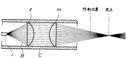
そして、このレーザビーム照射トーチfは、図6に示すように、これを旋回駆動するための旋回駆動部iに連結され、その軸心部に光ファイバーケーブルjを備えた筒体kに、レーザビームBを屈折する第一凸レンズl及び第二凸レンズmと、このレーザビームBを反射するミラーnを備えたものであり、光ファイバーケーブルjの端部から発せられた拡散ビームを第一凸レンズlで並行ビームに屈折すると共に、この並行ビームを第二凸レンズmで収束ビームに屈折した後、この収束ビームをミラーnによって筒体kの径方向外方に反射し、その照射孔oから小口径管c内壁に、収束された高エネルギーのレーザビームを照射して溶接を行うものである。そして、このレーザビーム照射トーチ6によるレーザビームの照射位置は、図7に示すように、照射によるクラッド材の溶融作業を効率的に行うために、すなわち、ある程度の照射面積を確保するために、レーザビームの焦点位置ではなく、その前後になるように制御されている。
【0005】
【発明が解決しようとする課題】
ところで、この照射位置でのレーザビームは、図7に示すように、第一凸レンズlで形成された並行ビームを、そのまま第二凸レンズmで収束したものであることから、図8に示すように、そのビーム強度分布は、照射位置の中心部がもっとも高く、その周辺部にいくに従って急激に低下するような鋭角な山型となっている。
【0006】
従って、このようなレーザビームで得られる溶接ビートも、図8に示すように、中央部の溶け込みが深く、かつ幅の狭い形状のものとなるため、母材への熱影響が大きく、しかも、効率の良いクラッド施工を行うのも困難であった。
【0007】
そこで本発明は、上記課題を解決するために案出されたものであり、その目的は、照射位置でのビーム強度を均一にして、幅の広い均一な溶接ビートを得ることができる新規なレーザビーム照射トーチを用いた照射方法を提供することにある。
【0008】
【課題を解決するための手段】
上記目的を達成するために本発明は、端部から高エネルギーレーザビームを照射する光ファイバーケーブルと、この光ファイバーケーブルから発せられる拡散ビームを並行ビームに屈折する第一凸レンズと、この並行ビームを収束する第二凸レンズとを備え、かつ、上記第二凸レンズの凸面側中央部に、上記並行ビームの入射角に対して直角に位置する平面部を形成したレーザビーム照射トーチを用い、上記第二凸レンズの焦点前後で、上記ビームの照射面積を上記平坦部の面積と略同一にしてレーザビームを照射することである。
【0009】
本発明は、上述したように第一凸レンズで得られた並行ビームを収束するための第二凸レンズの凸面側中央部に平面部を形成したことにより、ビーム強度が中心部とその周辺部で略均一なレーザビームが得られる。従って、このようなビーム強度分布を有するレーザビームを小口径管内壁のクラッド材の溶接に用いることで、深さが浅く、かつ幅の広い均一な溶接ビートが得られる。また、この平面部の面積を、照射面積と略同一にすることにより、ビーム強度が中心部より周縁部の方がやや高くなり、このようなレーザビームを用いることにより、さらに良好なる溶接ビートが得られる。
【0010】
【発明の実施の形態】
以下、本発明の実施の一形態を添付図面に基づいて詳述する。
【0011】
図1は本発明に係るレーザビーム照射トーチを示したものである。図示するように、このレーザビーム照射トーチは筒体1内に、0.8mmφ程度の光ファイバーケーブル2と、15mmφ程度の第一凸レンズ3及び第二凸レンズ4とが収容されている。
【0012】
この光ファイバーケーブル2は筒体1の軸心部に固定され、前述したレーザ発振手段から発生した高エネルギーのレーザビームBを導いてその端部から拡散ビームとして放射するようになっている。
【0013】
第一凸レンズ3はファイバーケーブル2側が平面状に形成され、その他面が凸状に加工されており、ファイバーケーブル2の端部から放射された拡散ビームB1 を並行ビームB2 に屈折するようになっている。
【0014】
一方、第二凸レンズ4は、その凸部が第一凸レンズ3側に面するように設置されており、第一凸レンズ3で得られた並行ビームB2 を収束するように屈折して溶接に用いる収束ビームB3 を得るようになっている。また、図2に示すように、この第二凸レンズ4の凸部側中央部には、並行ビームB2 の入射角に対して直角に入射するように平面状にカットされた2mmφ程度の円形カット部5が形成されており、そのカット部5に入射した並行ビームB2 を収束することなく、そのまま通過させるようになっている。尚、この第二凸レンズ4は、第一凸レンズ3に対して近接離間自在となっており、第一凸レンズ3からの焦点距離を任意に設定できるようになっている。
【0015】
次に、本実施の形態のレーザビーム照射トーチを用いた照射方法について説明する。図1に示すように、先ず、光ファイバーケーブル2の端部から放射されたレーザビームBは拡散ビームB1となって距離Xの位置にある第一凸レンズ3の平面側に達し、ここを通過する際に筐体1の軸心側に屈折されて、並行ビームB2となった後、第二凸レンズ4の凸部側に達し、これを通過する。このとき、第二凸レンズ4の周辺部、すなわち球面部を通過する並行ビームB2はさらに筐体1の軸心側に屈折されて収束ビームB3となり、この第二凸レンズ4から距離Zの位置で焦点を形成することになるが、この第二凸レンズ4の中央部のカット部5を通過する並行ビームB2はそのまま並行ビームB2の状態でこの第二凸レンズ4を通過して、第二凸レンズ4から距離Yにある照射位置に達することになる。
【0016】
このようにして得られた照射位置におけるビームは、図3に示すようにビーム強度が中心部から周辺部にかけて略均一な並行ビームB2 と、中心部より周辺部のほうがビーム強度の高い収束ビームB3 との合成ビーム(B2 +B3 )となり、そのビーム強度分布は、照射位置の中心部より周縁部のほうがやや高くなり、従来のような中心部のビーム強度が大きい山型とは異なり、半径方向rに分散して略台形を呈することになる。
【0017】
そして、このようなビーム強度分布をもつレーザビームBを用いて上述したようなクラッド施工を行った場合、その溶接ビートは、図3に示すように、幅広で、浅溶け込みのものが得られることになる。尚、このように強度分布が中心部より周辺部の方が大きいビームを用いても、図示するように、溶接ビートの深さが均一になるのは、溶接ビートの中心部では入熱した熱が逃げないのに対し、その周辺部では入熱のうち、ある程度の熱がその周囲に逃げてしまい結果的に中心部と周辺部とでは溶融に要する入熱の総量が均一になるからである。また、本形態においては、この第二凸レンズ4の中央部のカット部5の面積は、レーザビームの照射位置における照射面積と、略同様に設定することが好ましい。すなわち、このカット部5の面積が照射面積より小さすぎると、ビーム強度が中心部に集中し、反対に、このカット部5の面積が大きすぎると、ビームの照射面積も増大してしまい、図3に示すような理想的な溶接ビート形状が得られないからである。
【0018】
【発明の効果】
以上要するに本発明によれば、平面部の面積を上記ビームの照射面積と略同一にしてレーザビームを照射することで、深さが浅く、かつ幅の広い均一な溶接ビートが容易に得られ、母材への熱影響を低減することが可能となる上に、効率的なクラッド施行を行うことができる等といった優れた効果を発揮する。
【図面の簡単な説明】
【図1】本発明の一形態を示す概略図である。
【図2】本発明に係る第二凸レンズを示す斜視図である。
【図3】本発明で得られるビーム強度分布及び溶接ビート形状を示す説明図である。
【図4】従来のレーザクラッド工法の概略を示す説明図である。
【図5】従来のレーザクラッド工法の工程を示す説明図である
【図6】従来のレーザビーム照射トーチの一例を示す縦断面図である。
【図7】従来のレーザビーム照射トーチで得られるビームを示す説明図である。
【図8】従来のレーザビーム照射トーチで得られるビーム強度分布及び溶接ビート形状を示す説明図である。
【符号の説明】
1 筒体
2 光ファイバーケーブル
3 第一凸レンズ
4 第二凸レンズ
5 平面部[0001]
BACKGROUND OF THE INVENTION
The present invention uses, for example, a laser beam irradiation torch used to form a reinforcing film such as a clad portion in a predetermined range on the inner wall of a small-diameter tube such as an in-core monitor housing that is attached to penetrate a reactor pressure vessel . It relates to the irradiation method .
[0002]
[Prior art]
In general, as shown in FIG. 4, a reactor pressure vessel that forms the core of a nuclear reactor facility is formed with a through hole b in the lower mirror part a, and a small diameter tube c such as an in-core monitor housing is formed in the through hole b. Is welded through. Further, in a plant constructed relatively early, the inner wall of the small-diameter pipe c is provided with a clad portion e which is alloyed to reinforce the strength of the region in order to prevent cracks in the peripheral region of the welded portion d. May be constructed.
[0003]
As a formation method of this clad part e, first, as shown in FIG. 5, mixing in the small-diameter pipe c is, for example, Cr: 4, Ni: 4, Mo: 0.5, Fe: 1. After applying a paste clad material made of metal powder to a thickness of about 0.3 to 0.4 mm, a laser beam irradiation torch f is inserted into the small-diameter tube c as shown in FIG. The clad material is irradiated with a high energy laser beam from the laser oscillation part h as shown in FIG. 5 while the laser beam irradiation torch f is swirled helically by the swivel means g. Is melted to form an alloy with the base material of the small-diameter pipe c, and a clad portion having a thickness of about 0.2 mm is welded.
[0004]
Then, as shown in FIG. 6, the laser beam irradiation torch f is connected to a turning drive unit i for driving the turning of the laser beam irradiation torch f, and a laser beam is applied to a cylindrical body k having an optical fiber cable j at its axial center. A first convex lens l and a second convex lens m that refract B and a mirror n that reflects the laser beam B are provided, and a diffused beam emitted from the end of the optical fiber cable j is paralleled by the first convex lens l. After being refracted into a beam and refracting the parallel beam into a convergent beam by the second convex lens m, the converged beam is reflected radially outward of the cylindrical body k by the mirror n, and the small diameter tube c is irradiated from the irradiation hole o. Welding is performed by irradiating the inner wall with a focused high-energy laser beam. And, as shown in FIG. 7, the irradiation position of the laser beam by this laser beam irradiation torch 6 is to efficiently perform the melting work of the clad material by irradiation, that is, to ensure a certain irradiation area. It is controlled so that it is not the focal position of the laser beam but before and after it.
[0005]
[Problems to be solved by the invention]
Incidentally, as shown in FIG. 8, the laser beam at this irradiation position is obtained by converging the parallel beam formed by the first convex lens l as it is by the second convex lens m as shown in FIG. The beam intensity distribution has the highest peak at the center of the irradiation position, and has a sharp mountain shape that decreases rapidly toward the periphery.
[0006]
Therefore, as shown in FIG. 8, the welding beat obtained with such a laser beam also has a deep central portion and a narrow shape, so that the heat effect on the base material is large, It was also difficult to perform efficient clad construction.
[0007]
Accordingly, the present invention has been devised in order to solve the above-mentioned problems, and its purpose is to provide a novel laser capable of making the beam intensity uniform at the irradiation position and obtaining a wide and uniform welding beat. An object of the present invention is to provide an irradiation method using a beam irradiation torch.
[0008]
[Means for Solving the Problems]
In order to achieve the above object, the present invention provides an optical fiber cable that irradiates a high energy laser beam from an end, a first convex lens that refracts a diffused beam emitted from the optical fiber cable into a parallel beam, and converges the parallel beam. A second convex lens , and a laser beam irradiation torch having a plane portion positioned at right angles to the incident angle of the parallel beam at a central portion on the convex surface side of the second convex lens. Before and after the focal point, the laser beam is irradiated with the irradiation area of the beam being substantially the same as the area of the flat portion .
[0009]
In the present invention, as described above, the plane portion is formed in the central portion on the convex surface side of the second convex lens for converging the parallel beam obtained by the first convex lens, so that the beam intensity is substantially reduced at the central portion and its peripheral portion. A uniform laser beam can be obtained. Therefore, a uniform welding beat having a shallow depth and a wide width can be obtained by using a laser beam having such a beam intensity distribution for welding the clad material of the inner wall of the small diameter pipe. In addition, by making the area of this flat part substantially the same as the irradiation area, the beam intensity is slightly higher in the peripheral part than in the central part, and by using such a laser beam, a better welding beat can be obtained. can get.
[0010]
DETAILED DESCRIPTION OF THE INVENTION
Hereinafter, an embodiment of the present invention will be described in detail with reference to the accompanying drawings.
[0011]
FIG. 1 shows a laser beam irradiation torch according to the present invention. As shown in the figure, this laser beam irradiation torch accommodates an
[0012]
The
[0013]
The first
[0014]
On the other hand, the second convex lens 4 is installed so that the convex portion faces the first
[0015]
Next, an irradiation method using the laser beam irradiation torch according to this embodiment will be described. As shown in FIG. 1, first, fiber-Lee bar laser beam emitted from the end portion of the cable 2 B reaches the flat surface side of the first
[0016]
As shown in FIG. 3, the beam at the irradiation position obtained in this way is a parallel beam B2 having a substantially uniform beam intensity from the central part to the peripheral part, and a convergent beam B3 having a higher beam intensity at the peripheral part than at the central part. The beam intensity distribution is slightly higher at the periphery than at the center of the irradiation position, and unlike the conventional mountain shape having a large beam intensity at the center, It will disperse to form a substantially trapezoid.
[0017]
When the above-described clad construction is performed using the laser beam B having such a beam intensity distribution, the welding beat has a wide and shallow penetration as shown in FIG. become. As shown in the figure, the weld beat has a uniform depth even when a beam having a greater intensity distribution in the periphery than in the center is used. This is because a certain amount of heat escapes to the periphery of the heat input in the peripheral part, and as a result, the total amount of heat input required for melting is uniform in the central part and the peripheral part. . In the present embodiment, the area of the cut portion 5 at the center of the second convex lens 4 is preferably set substantially the same as the irradiation area at the laser beam irradiation position. That is, if the area of the cut portion 5 is too smaller than the irradiation area, the beam intensity is concentrated in the center portion. Conversely, if the area of the cut portion 5 is too large, the irradiation area of the beam also increases. This is because an ideal welding beat shape as shown in FIG.
[0018]
【The invention's effect】
In short, according to the present invention, a uniform welding beat having a shallow depth and a wide width can be easily obtained by irradiating the laser beam with the area of the plane portion being substantially the same as the irradiation area of the beam , In addition to being able to reduce the thermal influence on the base material, it exhibits excellent effects such as efficient clad execution.
[Brief description of the drawings]
FIG. 1 is a schematic view illustrating one embodiment of the present invention.
FIG. 2 is a perspective view showing a second convex lens according to the present invention.
FIG. 3 is an explanatory diagram showing a beam intensity distribution and a welding beat shape obtained by the present invention.
FIG. 4 is an explanatory view showing an outline of a conventional laser cladding method.
FIG. 5 is an explanatory view showing a process of a conventional laser cladding method. FIG. 6 is a longitudinal sectional view showing an example of a conventional laser beam irradiation torch.
FIG. 7 is an explanatory view showing a beam obtained by a conventional laser beam irradiation torch.
FIG. 8 is an explanatory diagram showing a beam intensity distribution and a welding beat shape obtained by a conventional laser beam irradiation torch.
[Explanation of symbols]
DESCRIPTION OF SYMBOLS 1
Claims (1)
Priority Applications (1)
| Application Number | Priority Date | Filing Date | Title |
|---|---|---|---|
| JP23825695A JP3605897B2 (en) | 1995-09-18 | 1995-09-18 | Irradiation method using laser beam irradiation torch |
Applications Claiming Priority (1)
| Application Number | Priority Date | Filing Date | Title |
|---|---|---|---|
| JP23825695A JP3605897B2 (en) | 1995-09-18 | 1995-09-18 | Irradiation method using laser beam irradiation torch |
Publications (2)
| Publication Number | Publication Date |
|---|---|
| JPH0976085A JPH0976085A (en) | 1997-03-25 |
| JP3605897B2 true JP3605897B2 (en) | 2004-12-22 |
Family
ID=17027483
Family Applications (1)
| Application Number | Title | Priority Date | Filing Date |
|---|---|---|---|
| JP23825695A Expired - Lifetime JP3605897B2 (en) | 1995-09-18 | 1995-09-18 | Irradiation method using laser beam irradiation torch |
Country Status (1)
| Country | Link |
|---|---|
| JP (1) | JP3605897B2 (en) |
Families Citing this family (3)
| Publication number | Priority date | Publication date | Assignee | Title |
|---|---|---|---|---|
| JP2003053577A (en) * | 2001-08-15 | 2003-02-26 | Sumitomo Heavy Ind Ltd | Method and device for generating top flat beam and method and device for laser beam machining using the top flat beam |
| JP4861997B2 (en) * | 2008-01-16 | 2012-01-25 | 東芝電波プロダクツ株式会社 | Far and near laser optics |
| IT201800003698A1 (en) * | 2018-03-16 | 2019-09-16 | Linea Light S R L | LIGHTING DEVICE |
-
1995
- 1995-09-18 JP JP23825695A patent/JP3605897B2/en not_active Expired - Lifetime
Also Published As
| Publication number | Publication date |
|---|---|
| JPH0976085A (en) | 1997-03-25 |
Similar Documents
| Publication | Publication Date | Title |
|---|---|---|
| TWI702105B (en) | Laser processing apparatus and method | |
| US5012066A (en) | Method of and apparatus for manufacturing eyeless suture needle | |
| US8404994B2 (en) | Laser beam welding device and method | |
| JP2021514841A (en) | Laser processing equipment and method | |
| US20220126396A1 (en) | Optical apparatus for the laser welding of a workpiece, with a plurality of partial beams having a core zone and a ring zone in the beam profile | |
| US3860784A (en) | Deep penetration welding using lasers | |
| CN110402179A (en) | Welding method and welder | |
| US20060102600A1 (en) | Laser welding device and method | |
| JP2021511967A (en) | Equipment and methods for laser machining materials | |
| US7285744B2 (en) | Method and apparatus for simultaneously heating materials | |
| UA124997C2 (en) | Method for butt laser welding two metal sheets with first and second front laser beams and a back laser beam | |
| JP2022517713A (en) | Methods for spatter-free welding, especially with solid-state lasers | |
| JP2003340582A (en) | Apparatus and method for laser welding | |
| JP3605897B2 (en) | Irradiation method using laser beam irradiation torch | |
| CN103476535A (en) | Laser welding method | |
| JPH06218567A (en) | Laser joining configuration | |
| JP6109638B2 (en) | Overlay welding apparatus and overlay welding system | |
| JPS60240395A (en) | Laser welding method | |
| CN107538133A (en) | A kind of hiding filling formula laser butt welding method based on beam shaping | |
| JP3040720B2 (en) | Laser processing head and laser processing method | |
| JP2020199513A (en) | Laser processing machine and control method of laser processing machine | |
| JP2002257968A (en) | Control rod for boiling water reactor | |
| JPH0819881A (en) | Laser beam device for heating of tubular body | |
| JP6549878B2 (en) | Laser light irradiation apparatus and laser peening method | |
| JPH0199789A (en) | Manufacture of welded pipe |
Legal Events
| Date | Code | Title | Description |
|---|---|---|---|
| A977 | Report on retrieval |
Free format text: JAPANESE INTERMEDIATE CODE: A971007 Effective date: 20040527 |
|
| A131 | Notification of reasons for refusal |
Free format text: JAPANESE INTERMEDIATE CODE: A131 Effective date: 20040608 |
|
| A521 | Written amendment |
Free format text: JAPANESE INTERMEDIATE CODE: A523 Effective date: 20040806 |
|
| TRDD | Decision of grant or rejection written | ||
| A01 | Written decision to grant a patent or to grant a registration (utility model) |
Free format text: JAPANESE INTERMEDIATE CODE: A01 Effective date: 20040914 |
|
| A61 | First payment of annual fees (during grant procedure) |
Free format text: JAPANESE INTERMEDIATE CODE: A61 Effective date: 20040927 |
|
| FPAY | Renewal fee payment (event date is renewal date of database) |
Free format text: PAYMENT UNTIL: 20071015 Year of fee payment: 3 |
|
| S531 | Written request for registration of change of domicile |
Free format text: JAPANESE INTERMEDIATE CODE: R313531 |
|
| S533 | Written request for registration of change of name |
Free format text: JAPANESE INTERMEDIATE CODE: R313533 |
|
| FPAY | Renewal fee payment (event date is renewal date of database) |
Free format text: PAYMENT UNTIL: 20071015 Year of fee payment: 3 |
|
| R350 | Written notification of registration of transfer |
Free format text: JAPANESE INTERMEDIATE CODE: R350 |
|
| FPAY | Renewal fee payment (event date is renewal date of database) |
Free format text: PAYMENT UNTIL: 20071015 Year of fee payment: 3 |
|
| FPAY | Renewal fee payment (event date is renewal date of database) |
Free format text: PAYMENT UNTIL: 20081015 Year of fee payment: 4 |
|
| FPAY | Renewal fee payment (event date is renewal date of database) |
Free format text: PAYMENT UNTIL: 20091015 Year of fee payment: 5 |
|
| FPAY | Renewal fee payment (event date is renewal date of database) |
Free format text: PAYMENT UNTIL: 20091015 Year of fee payment: 5 |
|
| FPAY | Renewal fee payment (event date is renewal date of database) |
Free format text: PAYMENT UNTIL: 20101015 Year of fee payment: 6 |
|
| FPAY | Renewal fee payment (event date is renewal date of database) |
Free format text: PAYMENT UNTIL: 20101015 Year of fee payment: 6 |
|
| FPAY | Renewal fee payment (event date is renewal date of database) |
Free format text: PAYMENT UNTIL: 20111015 Year of fee payment: 7 |
|
| FPAY | Renewal fee payment (event date is renewal date of database) |
Free format text: PAYMENT UNTIL: 20121015 Year of fee payment: 8 |
|
| FPAY | Renewal fee payment (event date is renewal date of database) |
Free format text: PAYMENT UNTIL: 20131015 Year of fee payment: 9 |
|
| EXPY | Cancellation because of completion of term |