JP3596980B2 - Fluid separation device - Google Patents
Fluid separation device Download PDFInfo
- Publication number
- JP3596980B2 JP3596980B2 JP12440196A JP12440196A JP3596980B2 JP 3596980 B2 JP3596980 B2 JP 3596980B2 JP 12440196 A JP12440196 A JP 12440196A JP 12440196 A JP12440196 A JP 12440196A JP 3596980 B2 JP3596980 B2 JP 3596980B2
- Authority
- JP
- Japan
- Prior art keywords
- fluid
- membrane element
- hole
- separation device
- membrane
- Prior art date
- Legal status (The legal status is an assumption and is not a legal conclusion. Google has not performed a legal analysis and makes no representation as to the accuracy of the status listed.)
- Expired - Fee Related
Links
Images

Landscapes
- Separation Using Semi-Permeable Membranes (AREA)
Description
【0001】
【発明の属する技術分野】
本発明は、筒形に形成された膜エレメントを有する流体分離装置に関する。
【0002】
【従来の技術】
流体の成分を分離するために、スパイラル型膜モジュール、プリーツ型膜モジュール、積層型膜モジュール等の流体分離装置が用いられている。このような流体分離装置は、原流体の流路を形成する第1の領域と透過流体の流路を形成する第2の領域とを仕切る透過性膜体および第2の領域に連通して透過流体を導出する有孔中空管を備えた筒形の膜エレメントを有し、原流体を透過流体と濃縮流体とに分離するものである。透過性膜体としては、比較的低圧のもとで使用される逆浸透膜、限外濾過膜、精密濾過膜等の分離膜が用いられる。この種の流体分離装置は、1個または直列に接続された複数個の膜エレメントを筒形容器内に装填することにより構成される。
【0003】
図2は従来の流体分離装置の一例を示す縦断面図である。図2の流体分離装置では、スパイラル型膜エレメントが2個使用されている。
図2において、スパイラル型膜エレメント21は、透過膜(透過性膜体)、原流体流路材および透過流体流路材を1組とする素材群を有孔中空管22の周りにスパイラル状に巻回することにより形成されている。図2の例では、2個の膜エレメント21がFRP(繊維強化プラスチック)、ステンレス鋼等からなる円筒容器26内に挿入されている。各膜エレメント21は、図中左方から供給される加圧された原流体を、透過膜を透過して有孔中空管22の内部に導かれる透過流体と、その残余の濃縮流体とに分離する。
【0004】
各膜エレメント21の中心部を通る有孔中空管22一端部どうしが内部継ぎ手25aにより連結されて2個の膜エレメント21が円筒容器26内に収納されている。一方の膜エレメント21の有孔中空管22の他端部(上流端)はキャップ28で封止されている。他方の膜エレメント21の有孔中空管22の他端部(下流端)は、端板23bの中心部から内側に向かって突出したハブ24に内部継ぎ手25bにより連結されている。
【0005】
膜エレメント1の外周面と円筒容器26の内周面との間には、原流体と濃縮流体との混合を防止するためのパッキン29が介挿されている。円筒容器26の両端はそれぞれ端板23a,23bで閉塞され、ボルト27により固着されている。一方の端板23aには原流体入口31aが形成され、他方の端板23bには濃縮流体出口31bが形成されている。また、他方の端板23bの中心部に形成されたハブ24には透過流体出口31cが穿孔されている。
【0006】
この流体分離装置においては、一方の端板23aの原流体入口31aから円筒容器26内に加圧された原流体が供給される。その原流体は、各膜エレメント21の原流体流路材に沿って流れ、他方の端板23bの濃縮流体出口31bから濃縮流体として排出される。原流体が膜エレメント21の原流体流路材に沿って流れる過程で透過膜を透過した透過流体が、透過流体流路材に沿って有孔中空管22内に導かれ、端板23bの透過流体出口31cから排出される。このようにして、原流体が透過流体と濃縮流体とに分離される。
【0007】
【発明が解決しようとする課題】
上記の従来の流体分離装置においては、円筒容器26、膜エレメント21およびパッキン29により形成されるデッドスペースSに流体が滞留する。この流体分離装置を長期間使用すると、デッドスペースSに滞留している流体が変性を起こす。特に、流体が有機物を含有する液体である場合には、微生物が繁殖し、この微生物が有機物を分解して悪臭を発生したり、透過膜を分解してしまうことがある。
【0008】
また、この流体分離装置を高い純度の透過水が要求される超純水製造ラインで使用する場合には、デッドスペースSに流体が滞留するため、透過水の純度の立ち上がりが非常に遅くなるという問題がある。
【0009】
さらに、従来の流体分離装置は、上記のように、膜エレメント21を円筒容器26内に収納することにより構成されているが、この円筒容器26の製造コストが流体分離装置の全体のコストに占める割合は非常に大きいものとなっている。そのため、流体分離装置の低価格化が図れないという問題がある。
【0010】
本発明の目的は、低価格化が可能でかつデッドスペースのない信頼性の高い流体分離装置を提供することである。
【0011】
【課題を解決するための手段および発明の効果】
本発明に係る流体分離装置は、原流体の流路を形成する第1の領域と透過流体の流路を形成する第2の領域とを仕切る透過性膜体および第2の領域に連通して透過流体を導出する有孔中空管を備えてなる筒形の膜エレメントを有し、原流体を透過流体と濃縮流体とに分離する流体分離装置において、膜エレメントの外周面に樹脂層を形成するとともに、膜エレメントの両端面が被覆されるように膜エレメントの両端面にそれぞれ樹脂層を形成し、膜エレメントの一方の端面の樹脂層に第1の領域に連通する第1の孔部を設け、かつ膜エレメントの他方の端面の樹脂層に第1の領域に連通する第2の孔部を設け、膜エレメントの少なくとも一方の端面の樹脂層に有孔中空管の内部に連通する第3の孔部を設けたものである。
【0012】
本発明に係る流体分離装置においては、筒形の膜エレメントの外周面および両端面が樹脂層で被覆されており、これらの樹脂層に膜エレメントの第1の領域に連通する第1および第2の孔部ならびに有孔中空管に連通する第3の孔部が設けられている。それにより、膜エレメントの外周部にデッドスペースが形成されないので、膜エレメントの外周部において流体の滞留が生じない。
【0013】
したがって、この流体分離装置を有機物を含有する流体の分離に使用した際に、微生物の繁殖、有機物の分解による悪臭の発生、透過性膜体の分解等の問題が起こらない。また、この流体分離装置を超純水製造ラインで使用した場合にも、透過水の純度の立ち上がりが良好となる。
【0014】
さらに、膜エレメントを収納するための筒形容器が不要となるため、製造コストが低減する。また、複数の流体分離装置の第1の孔部と第2の孔部を連結することにより、複数の膜エレメントを容易に接続することができ、また複数の膜エレメントの接続段数を容易に変更することができる。
【0015】
このように、低価格化が可能でかつデッドスペースのない信頼性の高い流体分離装置が提供される。
特に、第1の孔部が原流体入口用の孔部であり、第2の孔部が濃縮流体出口用の孔部であり、第3の孔部が透過流体出口用の孔部であってもよい。この場合、原流体は樹脂層の第1の孔部から膜エレメントの第1の領域に供給される。その原流体は、第1の領域を流れ、樹脂層の第2の孔部から濃縮流体として導出される。原流体が第1の領域を流れる過程で透過性膜体を透過した透過流体は、第2の領域を流れて有孔中空管の内部に導かれ、樹脂層の第3の孔部から排出される。
【0016】
膜エレメントは、透過性膜体、原流体流路材および透過流体流路材からなる1組または複数組の素材群を有孔中空管の外周面に配設したものであってもよい。その場合、原流体流路材により第1の領域における原流体の流路が確保され、透過流体流路材により第2の領域における透過流体の流路が確保される。
【0017】
また、第1の孔部および第2の孔部は、膜エレメントの端面の中心部から外周部に向かって等しい距離の位置に設けることが好ましい。それにより、複数個の膜エレメントの直列接続を容易に行なうことができる。
【0018】
【発明の実施の形態】
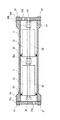
図1(a)は本発明の一実施例における流体分離装置の縦断面図、図1(b)は図1(a)の流体分離装置の端部の横断面図である。本実施例では、スパイラル型膜エレメントを有する流体分離装置について説明する。
【0019】
図1において、スパイラル型膜エレメント1は、透過膜(透過性膜体)、原流体流路材および透過流体流路材からなる1組の素材群を有孔中空管2の周りにスパイラル状に巻回することにより形成されている。
【0020】
膜エレメント1の外周面は、全幅に亘って例えばFRP等からなる樹脂層3で被覆されている。この樹脂層3は、膜エレメント1の外周面を密閉して保護する作用を有している。膜エレメント1の両端面は、例えばエポキシ樹脂、ウレタン樹脂、シリコン樹脂等からなる樹脂層4a,4bでそれぞれ被覆され、密閉されている。
【0021】
一方の樹脂層4aには原流体入口5が形成され、他方の樹脂層4bには濃縮流体出口6が形成されている。これらの原流体入口5および濃縮流体出口6は有孔中空管2を中心として外周部に向って等しい距離の位置に設けられている。また、樹脂層4a,4bの表面は有孔中空管2の両端面とそれぞれ面一に形成されている。それにより、有孔中空管2の両端の開口部が樹脂層4a,4bの表面に露出している。有孔中空管2の両端の開口部が透過流体出口7となる。
【0022】
次に、図1の流体分離装置の製造方法の一例を説明する。まず、有孔中空管2の周りに素材群を巻回し、最外周をテープ等で補強することによりスパイラル型膜エレメント1を形成する。そして、ガラス繊維を樹脂に含浸させて、いわゆるフィラメントワインディング法によりその樹脂を膜エレメント1の外周面の全幅に亘って巻付け、硬化させる。その後、その樹脂の両端を所定の長さに切断する。このようにして、膜エレメント1の外周面が樹脂層3で覆われる。
【0023】
次に、外周面が樹脂層3で覆われた膜エレメント1を例えばエポキシ樹脂、ウレタン樹脂、シリコン樹脂等に浸漬して含浸させ、硬化させることにより、膜エレメント1の両端面をそれぞれ樹脂層4a,4bで被覆する。このとき、所定の型枠を用いることにより、一方の樹脂層4aに原流体入口5を形成し、他方の樹脂層4bに濃縮流体出口6を形成する。また、樹脂層4a,4bの表面が有孔中空管2の端面と面一になるように樹脂の厚さを調整する。
【0024】
このようにして製造された流体分離装置においては、原流体が原流体入口5から膜エレメント1の素材群に供給される。素材群に供給された原流体は、原流体流路材に沿って流れ、濃縮流体出口6から濃縮流体として導出される。原流体が原流体流路材に沿って流れる過程で透過膜を透過した透過流体は、透過流体流路材に沿って有孔中空管2の内部に導かれ、透過流体出口7から取り出される。このようにして、原流体が濃縮流体と透過流体とに分離される。
【0025】
本実施例の流体分離装置においては、膜エレメント1の外周面が直接樹脂層3で覆われているので、膜エレメント1の外周部にデッドスペースが形成されない。そのため、この流体分離装置を有機物を含有する液体等の分離に使用した際に、デッドスペースにおいて生ずる微生物の繁殖、有機物の分解による悪臭の発生、透過膜の分解等の不具合が発生しない。また、この流体分離装置を超純水製造ラインで使用した場合にも、透過水の純度の立ち上がりが良好となる。さらに、膜エレメント1を収納するための筒形容器が不要となるため、製造コストが低減する。
【0026】
以上、流体分離装置を単体で使用する場合について説明したが、複数個の流体分離装置を接続して使用することも可能である。この場合、隣接する流体分離装置において、一方の流体分離装置の樹脂層4bに形成された濃縮流体出口6と他方の流体分離装置の樹脂層4aに形成された原流体入口5とを管継ぎ手等の連結部材およびOリング等のシール材を用いて連結する。これにより、複数の膜エレメント1を容易に接続することができ、また膜エレメント1の接続段数を容易に変更することができる。
【0027】
上記実施例では、スパイラル型膜エレメント1が有孔中空管2の周りに1組の素材群を巻回することにより構成される単葉型のエレメントである場合を説明したが、スパイラル型膜エレメント1が2組以上の素材群を重ねて有孔中空管2の周りに巻回することにより構成される複葉型の膜エレメントであってもよい。
【0028】
また、スパイラル型膜エレメント1の代わりにプリーツ型膜エレメント、積層型膜エレメント等の他の形態の膜エレメントを使用してもよい。
【図面の簡単な説明】
【図1】本発明の一実施例における流体分離装置の縦断面図および横断面図である。
【図2】従来の流体分離装置の一例を示す縦断面図である。
【符号の説明】
1 スパイラル型膜エレメント
2 有孔中空管
3,4a,4b 樹脂層
5 原流体入口
6 濃縮流体出口
7 透過流体出口[0001]
TECHNICAL FIELD OF THE INVENTION
The present invention relates to a fluid separation device having a membrane element formed in a cylindrical shape.
[0002]
[Prior art]
In order to separate components of a fluid, a fluid separation device such as a spiral-type membrane module, a pleated-type membrane module, or a stacked-type membrane module is used. Such a fluid separation device communicates with the permeable membrane that separates the first region forming the flow path of the raw fluid from the second region forming the flow path of the permeated fluid, and communicates with the second region. It has a cylindrical membrane element provided with a perforated hollow tube for taking out a fluid, and separates a raw fluid into a permeated fluid and a concentrated fluid. As the permeable membrane, a separation membrane such as a reverse osmosis membrane, an ultrafiltration membrane, or a microfiltration membrane used under relatively low pressure is used. This type of fluid separation device is constituted by loading one or a plurality of membrane elements connected in series into a cylindrical container.
[0003]
FIG. 2 is a longitudinal sectional view showing an example of a conventional fluid separation device. In the fluid separation device of FIG. 2, two spiral membrane elements are used.
In FIG. 2, a spiral-
[0004]
One end of a perforated hollow tube 22 passing through the center of each
[0005]
Between the outer peripheral surface of the membrane element 1 and the inner peripheral surface of the
[0006]
In this fluid separation device, pressurized raw fluid is supplied into the
[0007]
[Problems to be solved by the invention]
In the above-described conventional fluid separation device, the fluid stays in the dead space S formed by the
[0008]
In addition, when this fluid separation device is used in an ultrapure water production line that requires high purity permeated water, since the fluid stays in the dead space S, the rise of the permeated water purity is extremely slow. There's a problem.
[0009]
Further, as described above, the conventional fluid separation device is configured by housing the
[0010]
An object of the present invention is to provide a highly reliable fluid separation device that can be reduced in cost and has no dead space.
[0011]
Means for Solving the Problems and Effects of the Invention
A fluid separation device according to the present invention communicates with a permeable membrane that separates a first region forming a flow path of a source fluid and a second region forming a flow path of a permeate fluid, and the second region. In a fluid separation device having a cylindrical membrane element having a perforated hollow tube for leading out a permeated fluid and separating a raw fluid into a permeated fluid and a concentrated fluid, a resin layer is formed on the outer peripheral surface of the membrane element In addition, a resin layer is formed on each end face of the membrane element so as to cover both end faces of the membrane element, and a first hole communicating with the first region is formed in the resin layer on one end face of the membrane element. A second hole communicating with the first region is provided in the resin layer on the other end face of the membrane element, and a second hole communicating with the inside of the perforated hollow tube is provided on the resin layer on at least one end face of the membrane element. 3 is provided.
[0012]
In the fluid separation device according to the present invention, the outer peripheral surface and both end surfaces of the cylindrical membrane element are covered with a resin layer, and the first and second fluid communication layers communicate with the first region of the membrane element. And a third hole communicating with the perforated hollow tube. As a result, no dead space is formed in the outer peripheral portion of the membrane element, so that no fluid remains in the outer peripheral portion of the membrane element.
[0013]
Therefore, when this fluid separation device is used for separating a fluid containing an organic substance, problems such as propagation of microorganisms, generation of offensive odor due to decomposition of the organic substance, and decomposition of the permeable membrane do not occur. Also, when the fluid separation device is used in an ultrapure water production line, the rise of the purity of the permeated water is improved.
[0014]
Further, since a cylindrical container for storing the membrane element is not required, the manufacturing cost is reduced. Further, by connecting the first hole and the second hole of the plurality of fluid separation devices, the plurality of membrane elements can be easily connected, and the number of connection stages of the plurality of membrane elements can be easily changed. can do.
[0015]
Thus, a highly reliable fluid separation device that can be reduced in cost and has no dead space is provided.
In particular, the first hole is a hole for a raw fluid inlet, the second hole is a hole for a concentrated fluid outlet, and the third hole is a hole for a permeated fluid outlet. Is also good. In this case, the raw fluid is supplied from the first hole of the resin layer to the first region of the membrane element. The raw fluid flows through the first region and is led out as a concentrated fluid from the second hole of the resin layer. The permeated fluid that has passed through the permeable membrane in the course of the flow of the original fluid through the first region flows through the second region, is guided into the perforated hollow tube, and is discharged from the third hole of the resin layer. Is done.
[0016]
The membrane element may be one in which one or a plurality of material groups composed of a permeable membrane, a raw fluid flow path material, and a permeate fluid flow path material are disposed on the outer peripheral surface of a perforated hollow tube. In this case, the flow path of the raw fluid in the first area is secured by the raw fluid flow path material, and the flow path of the permeated fluid in the second area is secured by the permeated fluid flow path material.
[0017]
Further, the first hole and the second hole are preferably provided at equal distances from the center of the end face of the membrane element toward the outer periphery. This makes it possible to easily connect a plurality of membrane elements in series.
[0018]
BEST MODE FOR CARRYING OUT THE INVENTION
FIG. 1A is a longitudinal sectional view of a fluid separator according to an embodiment of the present invention, and FIG. 1B is a transverse sectional view of an end of the fluid separator of FIG. 1A. In this embodiment, a fluid separation device having a spiral membrane element will be described.
[0019]
In FIG. 1, a spiral-type membrane element 1 includes a set of material groups including a permeable membrane (permeable membrane), a raw fluid flow path material, and a permeable fluid flow path material. It is formed by winding around.
[0020]
The outer peripheral surface of the membrane element 1 is covered with a
[0021]
A raw fluid inlet 5 is formed in one
[0022]
Next, an example of a method for manufacturing the fluid separation device of FIG. 1 will be described. First, a material group is wound around a perforated
[0023]
Next, the membrane element 1 whose outer peripheral surface is covered with the
[0024]
In the fluid separation device manufactured as described above, the raw fluid is supplied to the raw material group of the membrane element 1 from the raw fluid inlet 5. The raw fluid supplied to the material group flows along the raw fluid flow path material, and is drawn out from the concentrated
[0025]
In the fluid separation device of the present embodiment, since the outer peripheral surface of the membrane element 1 is directly covered with the
[0026]
The case where the fluid separation device is used alone has been described above, but it is also possible to connect and use a plurality of fluid separation devices. In this case, in the adjacent fluid separator, the concentrated
[0027]
In the above embodiment, the case where the spiral membrane element 1 is a single-leaf element formed by winding a set of material groups around the perforated
[0028]
Further, in place of the spiral membrane element 1, another type of membrane element such as a pleated membrane element or a laminated membrane element may be used.
[Brief description of the drawings]
FIG. 1 is a longitudinal sectional view and a transverse sectional view of a fluid separation device according to an embodiment of the present invention.
FIG. 2 is a longitudinal sectional view showing an example of a conventional fluid separation device.
[Explanation of symbols]
DESCRIPTION OF SYMBOLS 1 Spiral
Claims (4)
Priority Applications (1)
| Application Number | Priority Date | Filing Date | Title |
|---|---|---|---|
| JP12440196A JP3596980B2 (en) | 1996-05-20 | 1996-05-20 | Fluid separation device |
Applications Claiming Priority (1)
| Application Number | Priority Date | Filing Date | Title |
|---|---|---|---|
| JP12440196A JP3596980B2 (en) | 1996-05-20 | 1996-05-20 | Fluid separation device |
Publications (2)
| Publication Number | Publication Date |
|---|---|
| JPH09299765A JPH09299765A (en) | 1997-11-25 |
| JP3596980B2 true JP3596980B2 (en) | 2004-12-02 |
Family
ID=14884541
Family Applications (1)
| Application Number | Title | Priority Date | Filing Date |
|---|---|---|---|
| JP12440196A Expired - Fee Related JP3596980B2 (en) | 1996-05-20 | 1996-05-20 | Fluid separation device |
Country Status (1)
| Country | Link |
|---|---|
| JP (1) | JP3596980B2 (en) |
-
1996
- 1996-05-20 JP JP12440196A patent/JP3596980B2/en not_active Expired - Fee Related
Also Published As
| Publication number | Publication date |
|---|---|
| JPH09299765A (en) | 1997-11-25 |
Similar Documents
| Publication | Publication Date | Title |
|---|---|---|
| US3401798A (en) | Cylindrically stacked and spirally configured semi-permeable membrane laminate apparatus | |
| EP0238737B1 (en) | Membrane assembly for fluid separation-disk | |
| US5460720A (en) | Pleated membrane crossflow fluid separation device | |
| US3494465A (en) | Selectively permeable membrane separation apparatus | |
| US7264725B2 (en) | Hollow fiber membrane contactor and method of making same | |
| KR101655489B1 (en) | Central core element for a spirally wound separator assembly | |
| CA2994035C (en) | Flexibly adaptable membrane cartridges for the separation of fluids | |
| JP2000157845A (en) | Hollow fiber membrane cartridge and its fixing structure | |
| US9975090B2 (en) | Double pass reverse osmosis separator module | |
| JPS6227007A (en) | Wound film candle filter | |
| JPH05212253A (en) | Hollow fiber bundle open at both ends and fluid separating device | |
| CN102186566A (en) | Spirally wound membrane separator assembly | |
| JPH04247224A (en) | Multiple bundle device for separating fluid | |
| CN102105211B (en) | Filtration system having fluid couplings | |
| US4761229A (en) | Multi-leaf membrane module | |
| JP2006281125A (en) | Spiral type membrane module | |
| JPH06142462A (en) | Hollow fiber made separating module having coated fiber bundle | |
| JP3596980B2 (en) | Fluid separation device | |
| CN110621393A (en) | Spiral wound module assembly including integrated pressure monitoring | |
| WO2012166834A2 (en) | Central core element for a separator assembly | |
| JPS58163404A (en) | Fluid separation apparatus | |
| WO1999058231A1 (en) | Hollow fiber type membrane module | |
| JPH09299766A (en) | Fluid separating device | |
| USRE26097E (en) | Michaels membrane separation device | |
| JPH10225625A (en) | Connecting method for liquid separation device and membrane element |
Legal Events
| Date | Code | Title | Description |
|---|---|---|---|
| A977 | Report on retrieval |
Free format text: JAPANESE INTERMEDIATE CODE: A971007 Effective date: 20040521 |
|
| A131 | Notification of reasons for refusal |
Free format text: JAPANESE INTERMEDIATE CODE: A131 Effective date: 20040608 |
|
| A521 | Written amendment |
Free format text: JAPANESE INTERMEDIATE CODE: A523 Effective date: 20040802 |
|
| TRDD | Decision of grant or rejection written | ||
| A01 | Written decision to grant a patent or to grant a registration (utility model) |
Free format text: JAPANESE INTERMEDIATE CODE: A01 Effective date: 20040907 |
|
| A61 | First payment of annual fees (during grant procedure) |
Free format text: JAPANESE INTERMEDIATE CODE: A61 Effective date: 20040907 |
|
| R150 | Certificate of patent or registration of utility model |
Free format text: JAPANESE INTERMEDIATE CODE: R150 |
|
| R250 | Receipt of annual fees |
Free format text: JAPANESE INTERMEDIATE CODE: R250 |
|
| FPAY | Renewal fee payment (event date is renewal date of database) |
Free format text: PAYMENT UNTIL: 20130917 Year of fee payment: 9 |
|
| LAPS | Cancellation because of no payment of annual fees |