JP3596251B2 - Ceiling-mounted air conditioner - Google Patents
Ceiling-mounted air conditioner Download PDFInfo
- Publication number
- JP3596251B2 JP3596251B2 JP26578897A JP26578897A JP3596251B2 JP 3596251 B2 JP3596251 B2 JP 3596251B2 JP 26578897 A JP26578897 A JP 26578897A JP 26578897 A JP26578897 A JP 26578897A JP 3596251 B2 JP3596251 B2 JP 3596251B2
- Authority
- JP
- Japan
- Prior art keywords
- mounting bracket
- opening
- plate portion
- underframe
- air conditioner
- Prior art date
- Legal status (The legal status is an assumption and is not a legal conclusion. Google has not performed a legal analysis and makes no representation as to the accuracy of the status listed.)
- Expired - Lifetime
Links
Images


Description
【0001】
【発明の属する技術分野】
本発明は、天井内に埋め込まれて設置される天井埋込形空気調和機に関するものである。
【0002】
【従来の技術】
従来のこの種空気調和機としては、例えば図22,図23,図24に示すように天井1の方向に開口を有した箱型の金属製台枠2を金属製台枠本体3と両側板4で構成し、そしてその金属製台枠2の内側には送風回路を構成するエアガイダ5,右側板6,左側板7を設けている。そして右側板6の下方に、モーター支持板8を設けてファンモーター9を支持するとともに、このファンモーター9の回転軸に送風作用を行なうクロスフローファン10の一端を連結し、また前記左側板7には軸受11を設け、クロスフローファン10の他端を連結している。また、熱交換を行う熱交換器12を右側板6,左側板7に接合し、熱交換器12の一方に配管と接続する補助配管13を設けている。さらに、前記金属製台枠2の内側において前記クロスフローファン10に送風作用を発揮させるスタビライザ14を設け、また熱交換器12の下方には熱交換器12から排出するドレン水を受ける水受皿15を設け、この水受皿15の下端を覆い金属製台枠2の下端を強化する底部16を設けている。水受皿15の一方には水受皿15に滞留したドレン水を機外に排出するドレンポンプ17を設けている。
【0003】
このように構成された空気調和機18の下方には天井1を介して空気調和機18の下方を覆う化粧パネル19を設けている。この化粧パネル19は金属製台枠2に取り付けられる。そして前記空気調和機18を固定するため、金属製台枠2の両側板4に電気溶接などで複数の吊り金具20を設け、この吊り金具20を吊りボルト21に対し吊りボルト21に螺合させたナット22を介して固定するようになっている。
【0004】
【発明が解決しようとする課題】
しかしながら、上記従来の構成の空気調和機は金属製部品点数が多く、製造する上で金属製部品点数をネジ止め、溶接するなど製造工数もかなりかかり、また本体重量もかなり重く運搬、施工時に多大な労力を要するばかりでなく、本体重量が重いが為に施工時に金属製台枠,吊り金具などの部品端面で手や身体に傷つけるなど安全性に欠けていた。また、空気調和機の取り換えなどの時に、古い空気調和機と新しい空気調和機の寸法が異なる場合は、天井から吊り下げられたボルトの位置を新しい空気調和機の寸法に合わし直す必要があるため施工面で問題があった。
【0005】
本発明は、このような課題を解決するもので、空気調和機を軽量化し、施工性ならびに安全性を向上させるようにすることを目的とするものである。
【0006】
【課題を解決するための手段】
上記課題を解決するために本発明は、空気調和機の台枠を合成樹脂で一体に形成すると共に、台枠の対向する面に金属製取付金具を設け、台枠から金属製取付金具を着脱自在にするものである。
【0007】
上記の構成によって、空気調和機を軽量化することとなり、製造工数の削減、作業性の向上、安全性の向上を図ることができる。
【0010】
【発明の実施の形態】
請求項1に記載の発明は、熱交換器、クロスフローファン、ファンモーター、ドレンポンプなどを内蔵する台枠を合成樹脂で一体に成形し、屋根裏から吊り下げられた吊りボルトに据え付ける着脱自在な取付金具と、前記取付金具と嵌合する取付金具固定部を前記台枠の対向する側面の前後両端近傍部に各々有している。取付金具は側面形状がL字形を呈し、上下方向に向く板部に開口部が形成され、水平方向に向く板部の先端に締め付け用ナットを備えた吊りボルトを挿入するほぼT字形の切り欠き穴が形成されており、取付金具固定部は前記台枠の側面からU字状に突出するように形成され外面の上端近傍部に前記取付金具の前記開口部が係合するように上方に膨らむ凸部を備えた弾性を有する爪片と、この爪片の外側を取り囲み前記取付金具の上下方向に向く板部が前記爪片の凸部から外れないように保持するための下端に開口部を持つ箱体のカバー部とを備え、このカバー部の上端に前記爪片と前記取付金具の上下方向に向く板部との係合を外すための開口部を形成してなるもので、製造工程を容易にし、施工現場で容易に取付金具を交換することができる。
【0011】
請求項2に記載の発明は、取付金具は側面形状がL字形を呈し、上下方向に向く板部に凸部を備えた弾性を有する爪片が形成され、水平方向に向く板部の先端に締め付け用ナットを備えた吊りボルトを挿入するほぼT字形の切り欠き穴が形成されており、一方、台枠側の前後両端近傍部には下端に開口部を持つ箱体の取付金具固定部を設け、この取付金具固定部は前記台枠の側面に前記取付金具の凸部が係合するように開口部と前記爪片の凸部から外れないように保持するためのカバー部とを備え、このカバー部の上端に前記開口部と上下方向に向く板部の爪片との係合を外すための開口部を形成してなるもので、施工現場で容易に取付金具を交換することができる。
【0012】
請求項3に記載の発明は、取付金具は水平方向に向く板部の長さの異なるものを備えてなり、請求項4に記載の発明は、取付金具は水平方向に向く板部が湾曲しているものを備えてなるもので、空気調和機の買い換え、取り換えなどのとき、古い空気調和機と新しい空気調和機の寸法が異なっても吊りボルトの付け替えを行う必要がなく、容易に空気調和機を据え付けることができる。
【0015】
請求項5に記載の発明は、取付金具は1枚の金属板の上端を2つ折りして、上下方向に向く2重構造の板部に開口部を形成し、2重構造の板部の一方にほぼT字形の切り欠き穴が形成されてなる水平方向に向く板部を連設し、この水平方向に向く板部よりも下方に突出する他方の板部の下端に水平方向に向く板部を連設し、この板部に化粧パネル固定穴を設けてなるもので、この構成により取付金具に化粧パネルをビス止めすることができる。
【0016】
【実施例】
以下本発明の実施例について図面を参照して説明する。
【0017】
先ず、本発明の第1実施例について説明すると、図1〜図3において、31は天井32内に埋め込まれた空気調和機本体、33は空気調和機本体31の下方に固定され天井32の表面に露出した化粧パネルである。34は化粧パネル33に設けた吸い込み部、35は化粧パネル33に設けた吹き出し開口部である。前記化粧パネル33は現場で施工業者により後付けとして設置される。36は空気調和機31の上半分を構成する合成樹脂製の台枠で、下端が開口している。
【0018】
37は送風作用を行うクロスフローファン、38はクロスフローファン37の軸39側を支持する軸受、40はクロスフローファン37のボス41側を支持するファンモーターである。42は室内空気と冷媒の熱交換を行う熱交換器、43は熱交換器42から機外へ導出する補助配管である。また、44は空気調和機の運転制御を行うコントロール部(図示なし)を収納する電源箱、45はファンモーター40を支持するファンモーター取付具である。また46は熱交換器42から排出されるドレン水を受ける合成樹脂の成形品と合成樹脂の発泡成型品(たとえば発泡スチロール成型品)を重合させて形成し、空気調和機の下部を構成する水受皿である。47は水受皿46の内部に設けられたドレンポンプである。
【0019】
ところで、前記台枠36の長手方向の両側面には空気調和機を吊り下げるため、屋根裏から吊り下げられた吊りボルト48に固定する複数個の取付金具49が設けられる。
【0020】
前記取付金具49と前記台枠36を接着,溶接,ネジ止めなどにより固定することにより合成樹脂の吊り下げ強度を得ることができる。
【0021】
また、前記取付金具49と前記台枠36を引っかけ構造にすることで製造工数を削減できる。
【0022】
図4〜図7は取付金具49及び台枠36に対する前記取付金具49の取り付け部とその係合状態を拡大して示しており、前記取付金具49は側面形状がL字形を呈し、上下方向に向く板部49aに矩形の開口部50が形成され、水平方向に向く板部49bの先端に吊りボルト48を挿入するほぼT字形の切り欠き穴51が形成されている。一方前記台枠36の両端部における前後両端近傍部に下端に開口部を持つ箱体の取付金具固定部52を設けてある。取付金具固定部52は前記台枠36の側面からU字状に突出するように形成され外面の上端近傍部に上方に膨らむ凸部53aを備えた爪片53と、この爪片53の外側を取り囲む下端開口のカバー部54とから構成され、前記爪片53の両側部および上端部における台枠36の側面は切り抜かれて爪片53に弾性を有らせしめている。55は前記爪片53の上部において前記カバー部54の上端に形成された開口部である。さらに、前記爪片53形成位置における台枠36の側面の内側は後述する爪片53と取付金具49の開口部50との係合を解除させる際の開口部55に対する治具の差し込みの邪魔にならないように構成されている。このような構成の取付金具固定部52の爪片53の凸部53aに取付金具49の開口部50を係合させて爪片53に取付金具49を取り付ける場合は、先ず取付金具49をカバー部54の下端開口から取付金具49の上下方向に向く板部49aを差し込み、前記開口部50を前記爪片53の凸部53aに係合させれば良い。このようにして台枠36に取り付けられた取付金具49の切り欠き穴51に前記吊りボルト48を嵌め込み、取付金具49の水平方向に向く板部49bの上下で吊りボルト48に螺合するナット56を前記板部49bに対し締め付けることにより空気調和機が吊りボルト48に吊り下げられる。なお、取付金具49の上下方向に向く板部49aの開口部50を爪片53の凸部53aに係合させた状態において、前記カバー部54の内面は上下方向に向く板部49aの外面に近接しており、上下方向に向く板部49aは爪片53の凸部53aから勝手に外れないようになっている。取付金具49を前記爪片53から外す場合は、適当な治具を用いて前記開口部55から爪片53を台枠36側に傾け、爪片53と取付金具49の開口部50との係合を外した状態で取付金具49を取付金具固定部52の下端から下方に移動させることで台枠36から取付金具49を簡単に外すことができる。
【0023】
上記構成において、合成樹脂製の空気調和機を吊り下げるには、本体荷重は下方に向くが、取付金具49は上下方向に向く板部49aの開口部50を爪片53の凸部53aに係合すること、およびカバー部54の内面は上下方向に向く板部49aの外面に近接していることから、取付金具49は台枠36から外れることなく、合成樹脂の吊り下げ強度を得ることができる。また、部品点数を削減できる。
【0024】
図8〜図10は取付金具49及び台枠36に対する前記取付金具49の取り付け部とその係合状態を拡大して示しており、前記取付金具49は側面形状がL字形を呈し、上下方向に向く板部49aに凸部53aを備えた爪片53から構成され、前記爪片53の両側部は切り抜かれて爪片53に弾性を有らせしめている。水平方向に向く板部49bの先端に吊りボルト48を挿入するほぼT字形の切り欠き穴51が形成されている。一方前記台枠36の両端部における前後両端近傍部に下端に開口部を持つ箱体の取付金具固定部52を設けてある。取付金具固定部52は前記台枠36の側面に矩形の開口部50が形成され、この開口部50の外側を取り囲む下端開口のカバー部54とから構成され、55は前記開口部50の上部において前記カバー部54の上端に形成された開口部である。さらに、前記開口部50形成位置における台枠36の側面の内側は後述する開口部50と取付金具49の爪片53との係合を解除させる際の開口部55に対する治具の差し込みの邪魔にならないように構成されている。このような構成の取付金具49の爪片53の凸部53aに取付金具固定部52の開口部50を係合させて取付金具49の爪片53に取付金具固定部52の開口部50を取り付ける場合は、先ず取付金具49をカバー部54の下端開口から取付金具49の上下方向に向く板部49aを差し込み、前記爪片53の凸部53aに前記開口部50を係合させれば良い。このようにして台枠36に取り付けられた取付金具49の切り欠き穴51に前記吊りボルト48を嵌め込み、取付金具49の水平方向に向く板部49bの上下で吊りボルト48に螺合するナット56を前記板部49bに対し締め付けることにより空気調和機が吊りボルト48に吊り下げられる。なお、取付金具49の上下方向に向く板部49aの爪片53の凸部53aを開口部50に係合させた状態において、前記カバー部54の内面は上下方向に向く板部49aの外面に近接しており、上下方向に向く板部49aは開口部50から勝手に外れないようになっている。取付金具49を前記開口部50から外す場合は、適当な治具を用いて前記開口部55から爪片53を台枠36と反対側に傾け、開口部50と取付金具49の爪片53との係合を外した状態で取付金具49を取付金具固定部52の下端から下方に移動させることで台枠36から取付金具49を簡単に外すことができる。
【0025】
上記構成において、合成樹脂製の空気調和機を吊り下げるには、本体荷重は下方に向くが、取付金具49は上下方向に向く板部49aの爪片53の凸部53aを開口部50に係合すること、およびカバー部54の内面は上下方向に向く板部49aの外面に近接していることから、取付金具49は台枠36から外れることなく、合成樹脂の吊り下げ強度を得ることができる。また、台枠36の樹脂成形も容易に行うことができる。
【0026】
ところで、前記取付金具49としては前記図4に示す構成の他、図11や図12に示す構成のものが使用される。前記図4に示す構成のものは水平方向に向く板部49bの長さが短いが、図11に示す構成のものは水平方向に向く板部49bの長さが長く、また図12に示す構成のものは水平方向に向く板部49bが湾曲している。そして、これらの取付金具49を適宜組み合わせることにより、図13〜図15に示すように吊りボルト48の位置に取付金具49の切り欠き穴51を合わせることができるものである。即ち、図13に示すように空気調和機本体31の長辺側における吊りボルト48間の距離がL1、短辺側における吊りボルト48間の距離がL2とした場合は、空気調和機本体31の両側部における前後両端近傍部に設けられる取付金具49は前記図4に示す取付金具を用いればよいが、図14に示すように空気調和機本体31の長辺側における吊りボルト48間の距離がL1+L3、短辺側における吊りボルト間の距離がL2とした場合は、空気調和機本体31の一側部における前後両端近傍部に設けられる取付金具49は前記図4に示す取付金具49を用いれば良く、空気調和機本体31の他側部における前後両端近傍部に設けられる取付金具49は前記図11に示す取付金具49を用いれば良い。さらに図15に示すように空気調和機31の長辺側における吊りボルト48間の距離L1、短辺側における吊りボルト48間の距離がL2+L4とした場合は、空気調和機31の両端部における前端近傍部に設けられる取付金具49は前記図4に示す取付金具49を用いれば良く、空気調和機本体31の両側部における後端近傍部に設けられる取付金具49は前記図12に示す取付金具49を用いれば良い。
【0027】
従って、係る複数種類の取付金具49を用いることにより、空気調和機の買い換え、取り換えなどのとき、古い空気調和機と新しい空気調和機の寸法が異なっても吊りボルト48の付け替えを行う必要がなく、容易に空気調和機を据え付けることができる。
【0028】
本発明の第7実施例について説明すると、図1〜図3において、31は天井32内に埋め込まれた空気調和機本体、33は空気調和機本体31の下方に固定され天井32の表面に露出した化粧パネルである。34は化粧パネル33に設けた吸い込み部、35は化粧パネル33に設けた吹き出し開口部である。前記化粧パネル33は現場で施工業者により後付けとして設置される。36は空気調和機31の上半分を構成する合成樹脂製の台枠で、下端が開口している。
【0029】
37は送風作用を行うクロスフローファン、38はクロスフローファン37の軸39側を支持する軸受、40はクロスフローファン37のボス41側を支持するファンモーターである。42は室内空気と冷媒の熱交換を行う熱交換器、43は熱交換器42から機外へ導出する補助配管である。また、44は空気調和機の運転制御を行うコントロール部(図示なし)を収納する電源箱、45はファンモーター40を支持するファンモーター取付具である。また46は熱交換器42から排出されるドレン水を受ける合成樹脂の成形品と合成樹脂の発泡成型品(たとえば発泡スチロール成型品)を重合させて形成し、空気調和機の下部を構成する水受皿である。47は水受皿46の内部に設けられたドレンポンプである。
【0030】
ところで、前記台枠36の長手方向の両側面には空気調和機を吊り下げるため、屋根裏から吊り下げられた吊りボルト48に固定する複数個の取付金具49が設けられる。
【0031】
前記取付金具49と前記台枠36を接着,密接,ネジ止めなどにより固定することにより合成樹脂の吊り下げ強度を得ることができる。
【0032】
また、前記取付金具49と前記台枠36の引っかけ構造を以下に説明する。図4〜図7の前記台枠36に対する取付金具49の取り付け部を拡大して示しており、前記取付金具49は側面形状がL字形を呈し、上下方向に向く板部49aに矩形の開口部50が形成され、水平方向に向く板部49bの先端に吊りボルト48を挿入するほぼT字形の切り欠き穴51が形成されている。一方前記台枠36の両端部における前後両端近傍部に下端に開口部を持つ箱体の取付金具固定部52を設けてある。取付金具固定部52は前記台枠36の側面からU字状に突出するように形成され外面の上端近傍部に上方に膨らむ凸部53aを備えた爪片53と、この爪片53の外側を取り囲む下端開口のカバー部54とから構成され、前記爪片53の両側部および上端部における台枠36の側面は切り抜かれて爪片53に弾性を有らせしめている。55は前記爪片53の上部において前記カバー部54の上端に形成された開口部である。さらに、前記爪片53形成位置における台枠36の側面の内側は後述する爪片53と取付金具49の開口部50との係合を解除させる際の開口部55に対する治具の差し込みの邪魔にならないように構成されている。このような構成の取付金具固定部52の爪片53の凸部53aに取付金具49の開口部50を係合させて爪片53に取付金具49を取り付ける場合は、先ず取付金具49をカバー部54の下端開口から取付金具49の上下方向に向く板部49aを差し込み、前記開口部50を前記爪片53の凸部53aに係合させれば良い。このようにして台枠36に取り付けられた取付金具49の切り欠き穴51に前記吊りボルト48を嵌め込み、取付金具49の水平方向に向く板部49bの上下で吊りボルト48に螺合するナット56を前記板部49bに対し締め付けることにより空気調和機が吊りボルト48に吊り下げられる。なお、取付金具49の上下方向に向く板部49aの開口部50を爪片53の凸部53aに係合させた状態において、前記カバー部54の内面は上下方向に向く板部49aの外面に近接しており、上下方向に向く板部49aは爪片53の凸部53aから勝手に外れないようになっている。取付金具49を前記爪片53から外す場合は、適当な治具を用いて前記開口部55から爪片53を台枠36側に傾け、爪片53と取付金具49の開口部50との係合を外した状態で取付金具49を取付金具固定部52の下端から下方に移動させることで台枠36から取付金具49を簡単に外すことができる。
【0033】
そして、図16〜図17に吊りボルト48に対する化粧パネル取付金具60の取付部を拡大して示しており、前記化粧パネル取付金具60はコ字形もしくはZ字形を呈し、水平方向に向く板部60aの先端に吊りボルト48を挿入するほぼT字形の切り欠き穴51が形成され、この水平方向に向く板部60aよりも下方に突出する他方の板部の下端に水平方向に向く板部57を連設し、化粧パネル取付金具60の切り欠き穴51に前記吊りボルト48を嵌め込み、化粧パネル取付金具60の水平方向に向く板部60aの上下で吊りボルト48に螺合するナット56を前記板部60aに対し締め付けることにより空気調和機が吊りボルト48に吊り下げられ、前記板部57に化粧パネル33固定用ねじ穴58を設けて、図17に示すように化粧パネル33をビス59により固定するように構成されている。
【0034】
さらに、化粧パネル取付金具60としては前記図16に示す構成の他、図18に示す構成のものも使用される。図18に示す構成のものは、前記化粧パネル取付金具60はコ字形もしくはZ字形を呈し、水平方向に向く板部60aの先端に取付金具49固定用ねじ穴61を設けて、この水平方向に向く板部60aよりも下方に突出する他方の板部の下端に水平方向に向く板部57を連設し、図19に示すように化粧パネル取付金具60を取付金具49にビスなどにより固定し、化粧パネル33をビス59により化粧パネル取付金具60に固定するように構成されている。
【0035】
さらに、取付金具49としては前記図4,図11,図12に示す構成の他、図20に示す構成のものも使用される。図20に示す構成のものは1枚の金属板の上端を2つ折りして、2重構造の板部に前記開口部50を形成し、2重構造の板部の一方に切り欠き穴51が形成されてなる水平方向に向く板部49bを連設し、この水平方向に向く板部49bよりも下方に突出する他方の板部の下端に水平方向に向く板部57を連設し、この板部57に化粧パネル33固定用ねじ穴58を設けて、図21に示すように化粧パネル33をビス59により固定するように構成されている。
【0036】
上記構成において、合成樹脂製の空気調和機を吊り下げるには、本体荷重は下方に向くが、取付金具49は上下方向に向く板部の開口部50を爪片53の凸部53aに係合すること、およびカバー部54の内面は上下方向に向く板部の外面に近接していることから、取付金具49は台枠36から外れることなく、合成樹脂の吊り下げ強度を得ることができる。また、万一取付金具固定部52が破損したとしても化粧パネル33が吊りボルト48に固定されているので空気調和機本体31を化粧パネル33により支えられるので空気調和機本体31の落下等を防ぐことができる。
【0039】
【発明の効果】
請求項1に記載の発明は、取付金具は側面形状がL字形を呈し、上下方向に向く板部に開口部が形成され、水平方向に向く板部の先端に締め付け用ナットを備えた吊りボルトを挿入するほぼT字形の切り欠き穴が形成されており、台枠側には前後両端近傍部に下端に開口部を持つ箱体の取付金具固定部を設け、この取付金具固定部は前記台枠の側面からU字状に突出するように形成され外面の上端近傍部に前記取付金具の前記開口部が係合するように上方に膨らむ凸部を備えた弾性を有する爪片と、この爪片の外側を取り囲み上下方向に向く板部が前記爪片の凸部から外れないように保持するためのカバー部とを備え、このカバー部の上端に前記爪片と上下方向に向く板部との係合を外すための開口部を形成してなるもので、製造上の部品点数削減、工数削減することができ、施工現場で容易に取付金具を交換することができる。
【0040】
請求項2に記載の発明は、取付金具は側面形状がL字形を呈し、上下方向に向く板部に凸部を備えた弾性を有する爪片が形成され、水平方向に向く板部の先端に締め付け用ナットを備えた吊りボルトを挿入するほぼT字形の切り欠き穴が形成されており、台枠側には前後両端近傍部に下端に開口部を持つ箱体の取付金具固定部を設け、この取付金具固定部は前記台枠の側面に前記取付金具の凸部が係合するように開口部と前記爪片の凸部から外れないように保持するためのカバー部とを備え、このカバー部の上端に前記開口部と上下方向に向く板部の爪片との係合を外すための開口部を形成してなるもので、合成樹脂台枠の取付金具固定部形状を開口部にすることで樹脂成形を容易にし、合成樹脂の反りなどの影響を受けないようにし、空気調和機を支える強度を得ることができる。
【0041】
請求項3に記載の発明は、取付金具は水平方向に向く板部の長さの異なるものを備えてなり、請求項4に記載の発明は、取付金具は水平方向に向く板部が湾曲してなるものを備えてなるもので、空気調和機の買い換え、取り替えなどのとき、古い空気調和機と新しい空気調和機の寸法が異なっても吊りボルトの付け替えを行う必要がなく、容易に空気調和機を据え付けることができる。
【0044】
請求項5に記載の発明は、取付金具は1枚の金属板の上端を2つ折りして、上下方向に向く2重構造の板部に開口部を形成し、2重構造の板部の一方にほぼT字形の切り欠き穴が形成されてなる水平方向に向く板部を連設し、この水平方向に向く板部よりも下方に突出する他方の板部の下端に水平方向に向く板部を連設し、この板部に化粧パネル固定穴を設けてなるもので、取付金具を2つ折りにすることで空気調和機本体の吊り強度を得ることができ、吊り金具と化粧パネルの取付金具を一体にすることで製造上の作業性、施工性の向上を得ることができる。また、空気調和機本体と化粧パネルとを吊りボルトで各々吊り下げることができることで、万が一台枠の取付金具固定部が破損した場合でも化粧パネルで空気調和機本体を支えることにより本体が落下する事はない。
【図面の簡単な説明】
【図1】本発明の実施例を示す空気調和機の取り付け部の正面図
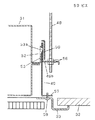
【図2】同空気調和機の取り付け部の側面断面図
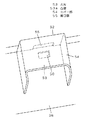
【図3】同空気調和機の分解斜視図
【図4】同取付金具の第1の例を示す斜視図
【図5】同空気調和機の取付金具固定部の拡大斜視図
【図6】同空気調和機の取付金具固定部の拡大断面図
【図7】同空気調和機の取付金具固定部と取付金具との係合状態を示す拡大断面図
【図8】同取付金具の第2の例を示す斜視図
【図9】同空気調和機の取付金具固定部の拡大斜視図
【図10】同空気調和機の取付金具固定部と取付金具との係合状態を示す拡大断面図
【図11】同取付金具の第3の例を示す斜視図
【図12】同取付金具の第4の例を示す斜視図
【図13】同空気調和機の第1の取付例を示す平面図
【図14】同空気調和機の第2の取付例を示す平面図
【図15】同空気調和機の第3の取付例を示す平面図
【図16】同取付金具の第5の例を示す斜視図
【図17】同第5の例の取付金具の使用例を示す拡大断面図
【図18】同取付金具の第6の例を示す斜視図
【図19】同第6の例の取付金具の使用例を示す拡大断面図
【図20】同取付金具の第7の例を示す斜視図
【図21】同第7の例の取付金具の使用例を示す拡大断面図
【図22】従来例を示す空気調和機の分解斜視図
【図23】同空気調和機の取り付け部の側面断面図
【図24】同空気調和機の取り付け部の要部拡大斜視図
【符号の説明】
31 空気調和機本体
32 天井
33 化粧パネル
34 吸い込み部
35 吹き出し開口部
36 台枠
37 クロスフローファン
40 ファンモーター
42 熱交換器
47 ドレンポンプ
48 吊りボルト
49 取付金具
49a 上下方向に向く板部
49b,57,60a 水平方向に向く板部
50,55 開口部
51 切り欠き穴
52 取付金具固定部
53 爪片
53a 凸部
54 カバー部
56 ナット
58 化粧パネル固定用ねじ穴
59 ビス
60 化粧パネル取付金具
61 化粧パネル取付金具固定用ねじ穴[0001]
TECHNICAL FIELD OF THE INVENTION
The present invention relates to a ceiling-mounted air conditioner embedded and installed in a ceiling.
[0002]
[Prior art]
As a conventional air conditioner of this type, for example, as shown in FIGS. 22, 23, and 24, a box-
[0003]
A
[0004]
[Problems to be solved by the invention]
However, the air conditioner with the conventional configuration described above has a large number of metal parts, requires a considerable amount of man-hours in manufacturing such as screwing and welding the metal parts, and has a considerably heavy body weight, which is extremely large during transportation and construction. Not only did it require a lot of labor, but also because of its heavy body weight, it lacked safety, such as damage to the hands and body at the end faces of parts such as metal underframes and hanging brackets during construction. Also, when replacing the air conditioner, if the dimensions of the old air conditioner and the new air conditioner are different, it is necessary to adjust the position of the bolts suspended from the ceiling to the dimensions of the new air conditioner. There was a problem in construction.
[0005]
An object of the present invention is to solve such a problem and to reduce the weight of an air conditioner and improve workability and safety.
[0006]
[Means for Solving the Problems]
In order to solve the above-mentioned problems, the present invention provides a frame of an air conditioner integrally formed of a synthetic resin, a metal mounting bracket provided on an opposing surface of the frame, and a metal mounting bracket attached to and detached from the frame. It is intended to be free.
[0007]
With the above configuration, the air conditioner can be reduced in weight, and the number of manufacturing steps can be reduced, workability can be improved, and safety can be improved.
[0010]
BEST MODE FOR CARRYING OUT THE INVENTION
Claim 1The described invention,A detachable mounting bracket that integrally molds a base frame containing a heat exchanger, a cross flow fan, a fan motor, a drain pump, and the like with synthetic resin, and that is mounted on a suspension bolt suspended from the attic, and fits with the mounting bracket Fitting fixing parts are provided in the vicinity of both front and rear ends of the opposing side surfaces of the underframe.The mounting bracket has an L-shaped side surface, an opening is formed in a vertically oriented plate portion, and a substantially T-shaped notch for inserting a suspension bolt provided with a fastening nut at a tip of the horizontally oriented plate portion. A hole is formed,The mounting bracket fixing portion is formed so as to protrude in a U-shape from the side surface of the underframe, and has an elasticity provided with a convex portion bulging upward so that the opening of the mounting bracket is engaged near the upper end of the outer surface. Having a nail piece and surrounding the outside of the nail pieceOf the mounting bracketFor holding the plate part facing in the vertical direction so as not to come off from the convex part of the claw pieceOf a box with an opening at the lower endA cover part, and the claw piece is provided at an upper end of the cover part.Of the mounting bracketAn opening for disengaging from a vertically oriented plate portion is formed, so that the manufacturing process can be facilitated and the mounting bracket can be easily replaced at the construction site.
[0011]
Claim 2According to the invention described in (1), the mounting bracket has an L-shaped side surface, an elastic claw piece having a convex portion is formed on the plate portion facing in the vertical direction, and a fastening nut is provided at a tip of the plate portion facing in the horizontal direction. A substantially T-shaped notch hole for inserting a suspension bolt withon the other hand,Underframe sideofNear the front and rear endsIsFixing the mounting bracket of a box with an opening at the lower endDepartmentThe mounting bracket fixing part includes an opening and a cover part for holding the mounting part so as not to come off from the projection of the claw piece so that the projection of the mounting bracket is engaged with the side surface of the underframe. At the upper end of the cover, an opening is formed at the upper end to disengage the opening and the claw piece of the plate portion facing in the vertical direction, so that the mounting bracket can be easily replaced at the construction site. it can.
[0012]
Claim 3In the invention described in the above, the mounting bracket is provided with one having a different length of the plate portion facing in the horizontal direction,Claim 4The invention described in (1) is characterized in that the mounting bracket is provided with a curved plate part that faces in the horizontal direction, and when replacing or replacing an air conditioner, the dimensions of the old air conditioner and the new air conditioner It is not necessary to replace the hanging bolts even if the air conditioner is different, and the air conditioner can be easily installed.
[0015]
Claim 5According to the invention described in the above, the mounting bracket is formed by folding an upper end of one metal plate into two, forming an opening in a vertically structured double-structured plate portion, and substantially forming T on one of the double-structured plate portions. A horizontally oriented plate portion formed with a letter-shaped cutout hole is continuously provided, and a horizontally oriented plate portion is continuously provided at the lower end of the other plate portion projecting below the horizontally directed plate portion. This plate portion is provided with a decorative panel fixing hole. With this configuration, the decorative panel can be screwed to the mounting bracket.
[0016]
【Example】
Hereinafter, embodiments of the present invention will be described with reference to the drawings.
[0017]
First, a first embodiment of the present invention will be described. In FIGS. 1 to 3,
[0018]
[0019]
By the way, in order to suspend the air conditioner on both sides in the longitudinal direction of the
[0020]
The hanging strength of the synthetic resin can be obtained by fixing the mounting
[0021]
In addition, the number of manufacturing steps can be reduced by forming the mounting
[0022]
4 to 7Are the mounting
[0023]
In the above configuration, in order to suspend the air conditioner made of synthetic resin, the main body load is directed downward, but the mounting
[0024]
8 to 10Are the mounting
[0025]
In the above configuration, in order to suspend the air conditioner made of synthetic resin, the main body load is directed downward, but the mounting
[0026]
Incidentally, as the mounting
[0027]
Therefore, by using such a plurality of types of mounting
[0028]
A description will be given of a seventh embodiment of the present invention. In FIGS. 1 to 3,
[0029]
[0030]
By the way, in order to suspend the air conditioner on both sides in the longitudinal direction of the
[0031]
The hanging strength of the synthetic resin can be obtained by fixing the mounting
[0032]
The hooking structure between the mounting
[0033]
FIGS. 16 and 17 show an enlarged view of a mounting portion of the decorative
[0034]
Further, as the decorative
[0035]
Further, as the mounting
[0036]
In the above configuration, when suspending the air conditioner made of synthetic resin, the main body load is directed downward, but the mounting
[0039]
【The invention's effect】
Claim 1According to the invention described in (1), the mounting bracket has an L-shaped side surface, an opening is formed in the plate portion facing in the vertical direction, and a hanging bolt provided with a fastening nut is inserted into a tip of the plate portion facing in the horizontal direction. A substantially T-shaped notch hole is formed, and a mounting bracket for a box body having an opening at the lower end near the front and rear ends on the underframe sideDepartmentThe mounting bracket fixing portion is formed so as to protrude in a U-shape from the side surface of the underframe, and has a convex portion bulging upward so as to be engaged with the opening of the mounting bracket near the upper end of the outer surface. A claw having elasticity provided, and a cover for surrounding the outside of the claw and holding a plate portion facing in the vertical direction so as not to come off from the convex portion of the claw is provided at an upper end of the cover. By forming an opening for disengaging the claw piece and the plate portion facing in the vertical direction, the number of parts in manufacturing can be reduced, the number of steps can be reduced, and the mounting bracket can be easily installed at the construction site. Can be exchanged.
[0040]
Claim 2According to the invention described in (1), the mounting bracket has an L-shaped side surface, an elastic claw piece having a convex portion is formed on the plate portion facing in the vertical direction, and a fastening nut is provided at a tip of the plate portion facing in the horizontal direction. A substantially T-shaped notch hole is formed for inserting a suspension bolt with a hole, and a mounting bracket for a box body having an opening at the lower end near the front and rear ends on the underframe side is fixed.DepartmentThe mounting bracket fixing part includes an opening and a cover part for holding the mounting part so as not to come off from the projection of the claw piece so that the projection of the mounting bracket is engaged with the side surface of the underframe. An opening is formed at the upper end of the cover to release the engagement between the opening and the claw piece of the plate facing in the vertical direction. By forming the portion, the resin molding is facilitated, the influence of the warp of the synthetic resin or the like is prevented, and the strength for supporting the air conditioner can be obtained.
[0041]
Claim 3In the invention described in the above, the mounting bracket is provided with one having a different length of the plate portion facing in the horizontal direction,Claim 4The invention described in (1) is characterized in that the mounting bracket is provided with a plate part that is curved in the horizontal direction and is curved. When replacing or replacing an air conditioner, the dimensions of the old air conditioner and the new air conditioner It is not necessary to replace the hanging bolts even if the air conditioner is different, and the air conditioner can be easily installed.
[0044]
Claim 5According to the invention described in the above, the mounting bracket is formed by folding an upper end of one metal plate into two, forming an opening in a vertically structured double-structured plate portion, and substantially forming T on one of the double-structured plate portions. A horizontally oriented plate portion formed with a letter-shaped cutout hole is continuously provided, and a horizontally oriented plate portion is continuously provided at the lower end of the other plate portion projecting below the horizontally directed plate portion. This plate portion is provided with a decorative panel fixing hole. By folding the mounting bracket into two, the suspension strength of the air conditioner main body can be obtained, and the hanging bracket and the mounting bracket for the decorative panel are integrally formed. By doing so, improvements in workability and workability in manufacturing can be obtained. In addition, since the air conditioner body and the decorative panel can be hung with hanging bolts, respectively,The mounting bracket fixing part of the underframe has been damaged.Even in this case, the main body does not fall by supporting the air conditioner main body with the decorative panel.
[Brief description of the drawings]
FIG. 1 is a front view of a mounting portion of an air conditioner showing an embodiment of the present invention.
FIG. 2 is a side sectional view of a mounting portion of the air conditioner.
FIG. 3 is an exploded perspective view of the air conditioner.
FIG. 4 is a perspective view showing a first example of the mounting bracket.
FIG. 5 is an enlarged perspective view of a mounting bracket fixing portion of the air conditioner.
FIG. 6 is an enlarged sectional view of a mounting bracket fixing portion of the air conditioner.
FIG. 7 is an enlarged sectional view showing an engagement state between the mounting bracket fixing portion and the mounting bracket of the air conditioner.
FIG. 8 is a perspective view showing a second example of the mounting bracket.
FIG. 9 is an enlarged perspective view of a mounting bracket fixing portion of the air conditioner.
FIG. 10 is an enlarged sectional view showing an engagement state between the mounting bracket fixing portion and the mounting bracket of the air conditioner.
FIG. 11 is a perspective view showing a third example of the mounting bracket.
FIG. 12 is a perspective view showing a fourth example of the mounting bracket.
FIG. 13 is a plan view showing a first mounting example of the air conditioner.
FIG. 14 is a plan view showing a second mounting example of the air conditioner.
FIG. 15 is a plan view showing a third mounting example of the air conditioner.
FIG. 16 is a perspective view showing a fifth example of the mounting bracket.
FIG. 17 is an enlarged sectional view showing an example of use of the mounting bracket of the fifth example.
FIG. 18 is a perspective view showing a sixth example of the mounting bracket.
FIG. 19 is an enlarged sectional view showing a usage example of the mounting bracket of the sixth example.
FIG. 20 is a perspective view showing a seventh example of the mounting bracket.
FIG. 21 is an enlarged sectional view showing a usage example of the mounting bracket of the seventh example.
FIG. 22 is an exploded perspective view of an air conditioner showing a conventional example.
FIG. 23 is a side sectional view of a mounting portion of the air conditioner.
FIG. 24 is an enlarged perspective view of a main part of a mounting portion of the air conditioner.
[Explanation of symbols]
31 Air conditioner body
32 ceiling
33 Makeup panel
34 Suction section
35 blowout opening
36 underframes
37 Cross Flow Fan
40 fan motor
42 heat exchanger
47 Drain pump
48 Hanging bolt
49 Mounting bracket
49a Vertically facing plate
49b, 57, 60a Horizontally facing plate
50, 55 opening
51 Notch hole
52 Mounting bracket fixing part
53 nail pieces
53a convex part
54 Cover
56 nuts
58 Decorative panel fixing screw holes
59 screws
60 decorative panel mounting bracket
61 Screw holes for fixing decorative panel mounting bracket
Claims (5)
Priority Applications (1)
| Application Number | Priority Date | Filing Date | Title |
|---|---|---|---|
| JP26578897A JP3596251B2 (en) | 1997-06-03 | 1997-09-30 | Ceiling-mounted air conditioner |
Applications Claiming Priority (3)
| Application Number | Priority Date | Filing Date | Title |
|---|---|---|---|
| JP14438697 | 1997-06-03 | ||
| JP9-144386 | 1997-06-03 | ||
| JP26578897A JP3596251B2 (en) | 1997-06-03 | 1997-09-30 | Ceiling-mounted air conditioner |
Publications (2)
| Publication Number | Publication Date |
|---|---|
| JPH1151461A JPH1151461A (en) | 1999-02-26 |
| JP3596251B2 true JP3596251B2 (en) | 2004-12-02 |
Family
ID=26475809
Family Applications (1)
| Application Number | Title | Priority Date | Filing Date |
|---|---|---|---|
| JP26578897A Expired - Lifetime JP3596251B2 (en) | 1997-06-03 | 1997-09-30 | Ceiling-mounted air conditioner |
Country Status (1)
| Country | Link |
|---|---|
| JP (1) | JP3596251B2 (en) |
Families Citing this family (4)
| Publication number | Priority date | Publication date | Assignee | Title |
|---|---|---|---|---|
| JP4416992B2 (en) * | 2002-08-30 | 2010-02-17 | 東芝キヤリア株式会社 | Air conditioner |
| CN104266264B (en) * | 2014-10-16 | 2016-09-21 | 上海圣峰建材科技有限公司 | A kind of Integral ceiling air-conditioning and mounting structure thereof |
| CN106524473A (en) * | 2016-12-21 | 2017-03-22 | 上海赛菲环境科技股份有限公司 | Totally-enclosed type hoisting foot for fresh air machine |
| JP7089185B2 (en) * | 2019-08-21 | 2022-06-22 | ダイキン工業株式会社 | Additional unit for air treatment equipment and air treatment unit |
-
1997
- 1997-09-30 JP JP26578897A patent/JP3596251B2/en not_active Expired - Lifetime
Also Published As
| Publication number | Publication date |
|---|---|
| JPH1151461A (en) | 1999-02-26 |
Similar Documents
| Publication | Publication Date | Title |
|---|---|---|
| JP3596251B2 (en) | Ceiling-mounted air conditioner | |
| JP3080086B2 (en) | Installation equipment and structure of air conditioner | |
| JP3085225B2 (en) | Air conditioner | |
| JP3615366B2 (en) | Ceiling suspended air conditioner | |
| JP2004085001A (en) | Indoor unit of air conditioner | |
| JP4523822B2 (en) | Embedded ceiling air conditioner | |
| JP2004085002A (en) | Indoor unit of air conditioner | |
| KR20100066178A (en) | Air conditioner | |
| JP2664472B2 (en) | Ceiling embedded air conditioning unit | |
| JP2543397Y2 (en) | Ceiling-mounted air conditioner | |
| JP2727736B2 (en) | Ceiling-mounted air conditioner | |
| JP3596219B2 (en) | Air blower for air conditioning | |
| JP2000274728A (en) | Air conditioner | |
| JP2004190991A (en) | Air conditioner | |
| JPH0216198Y2 (en) | ||
| KR200225294Y1 (en) | Air conditioner | |
| JP2005164073A (en) | Air conditioning system | |
| JPH076687B2 (en) | Ceiling embedded air conditioner | |
| JPS5838326Y2 (en) | Ceiling-suspended air conditioner | |
| JPH0440112Y2 (en) | ||
| JP2001099481A (en) | Air conditioner flush with ceiling | |
| JPH023093B2 (en) | ||
| JPH073220Y2 (en) | Mounting structure of fan plate and panel in air conditioner | |
| JPH0330734Y2 (en) | ||
| JPH033861Y2 (en) |
Legal Events
| Date | Code | Title | Description |
|---|---|---|---|
| A131 | Notification of reasons for refusal |
Free format text: JAPANESE INTERMEDIATE CODE: A131 Effective date: 20040309 |
|
| A521 | Written amendment |
Free format text: JAPANESE INTERMEDIATE CODE: A523 Effective date: 20040510 |
|
| TRDD | Decision of grant or rejection written | ||
| A01 | Written decision to grant a patent or to grant a registration (utility model) |
Free format text: JAPANESE INTERMEDIATE CODE: A01 Effective date: 20040817 |
|
| A61 | First payment of annual fees (during grant procedure) |
Free format text: JAPANESE INTERMEDIATE CODE: A61 Effective date: 20040830 |
|
| FPAY | Renewal fee payment (event date is renewal date of database) |
Free format text: PAYMENT UNTIL: 20080917 Year of fee payment: 4 |
|
| FPAY | Renewal fee payment (event date is renewal date of database) |
Free format text: PAYMENT UNTIL: 20080917 Year of fee payment: 4 |
|
| FPAY | Renewal fee payment (event date is renewal date of database) |
Free format text: PAYMENT UNTIL: 20090917 Year of fee payment: 5 |
|
| FPAY | Renewal fee payment (event date is renewal date of database) |
Free format text: PAYMENT UNTIL: 20090917 Year of fee payment: 5 |
|
| FPAY | Renewal fee payment (event date is renewal date of database) |
Free format text: PAYMENT UNTIL: 20100917 Year of fee payment: 6 |
|
| FPAY | Renewal fee payment (event date is renewal date of database) |
Free format text: PAYMENT UNTIL: 20110917 Year of fee payment: 7 |
|
| FPAY | Renewal fee payment (event date is renewal date of database) |
Free format text: PAYMENT UNTIL: 20120917 Year of fee payment: 8 |
|
| FPAY | Renewal fee payment (event date is renewal date of database) |
Free format text: PAYMENT UNTIL: 20130917 Year of fee payment: 9 |
|
| EXPY | Cancellation because of completion of term |