JP3595337B2 - Flow measuring device - Google Patents
Flow measuring device Download PDFInfo
- Publication number
- JP3595337B2 JP3595337B2 JP52011494A JP52011494A JP3595337B2 JP 3595337 B2 JP3595337 B2 JP 3595337B2 JP 52011494 A JP52011494 A JP 52011494A JP 52011494 A JP52011494 A JP 52011494A JP 3595337 B2 JP3595337 B2 JP 3595337B2
- Authority
- JP
- Japan
- Prior art keywords
- flow
- conduit
- notch opening
- tube
- measuring device
- Prior art date
- Legal status (The legal status is an assumption and is not a legal conclusion. Google has not performed a legal analysis and makes no representation as to the accuracy of the status listed.)
- Expired - Fee Related
Links
Images


Classifications
-
- A—HUMAN NECESSITIES
- A61—MEDICAL OR VETERINARY SCIENCE; HYGIENE
- A61M—DEVICES FOR INTRODUCING MEDIA INTO, OR ONTO, THE BODY; DEVICES FOR TRANSDUCING BODY MEDIA OR FOR TAKING MEDIA FROM THE BODY; DEVICES FOR PRODUCING OR ENDING SLEEP OR STUPOR
- A61M16/00—Devices for influencing the respiratory system of patients by gas treatment, e.g. mouth-to-mouth respiration; Tracheal tubes
- A61M16/0051—Devices for influencing the respiratory system of patients by gas treatment, e.g. mouth-to-mouth respiration; Tracheal tubes with alarm devices
-
- A—HUMAN NECESSITIES
- A61—MEDICAL OR VETERINARY SCIENCE; HYGIENE
- A61B—DIAGNOSIS; SURGERY; IDENTIFICATION
- A61B5/00—Measuring for diagnostic purposes; Identification of persons
- A61B5/08—Detecting, measuring or recording devices for evaluating the respiratory organs
- A61B5/087—Measuring breath flow
-
- A—HUMAN NECESSITIES
- A61—MEDICAL OR VETERINARY SCIENCE; HYGIENE
- A61M—DEVICES FOR INTRODUCING MEDIA INTO, OR ONTO, THE BODY; DEVICES FOR TRANSDUCING BODY MEDIA OR FOR TAKING MEDIA FROM THE BODY; DEVICES FOR PRODUCING OR ENDING SLEEP OR STUPOR
- A61M16/00—Devices for influencing the respiratory system of patients by gas treatment, e.g. mouth-to-mouth respiration; Tracheal tubes
- A61M16/021—Devices for influencing the respiratory system of patients by gas treatment, e.g. mouth-to-mouth respiration; Tracheal tubes operated by electrical means
- A61M16/022—Control means therefor
-
- A—HUMAN NECESSITIES
- A61—MEDICAL OR VETERINARY SCIENCE; HYGIENE
- A61M—DEVICES FOR INTRODUCING MEDIA INTO, OR ONTO, THE BODY; DEVICES FOR TRANSDUCING BODY MEDIA OR FOR TAKING MEDIA FROM THE BODY; DEVICES FOR PRODUCING OR ENDING SLEEP OR STUPOR
- A61M16/00—Devices for influencing the respiratory system of patients by gas treatment, e.g. mouth-to-mouth respiration; Tracheal tubes
- A61M16/08—Bellows; Connecting tubes ; Water traps; Patient circuits
- A61M16/0816—Joints or connectors
- A61M16/0841—Joints or connectors for sampling
- A61M16/0858—Pressure sampling ports
-
- G—PHYSICS
- G01—MEASURING; TESTING
- G01F—MEASURING VOLUME, VOLUME FLOW, MASS FLOW OR LIQUID LEVEL; METERING BY VOLUME
- G01F1/00—Measuring the volume flow or mass flow of fluid or fluent solid material wherein the fluid passes through a meter in a continuous flow
- G01F1/05—Measuring the volume flow or mass flow of fluid or fluent solid material wherein the fluid passes through a meter in a continuous flow by using mechanical effects
- G01F1/34—Measuring the volume flow or mass flow of fluid or fluent solid material wherein the fluid passes through a meter in a continuous flow by using mechanical effects by measuring pressure or differential pressure
- G01F1/36—Measuring the volume flow or mass flow of fluid or fluent solid material wherein the fluid passes through a meter in a continuous flow by using mechanical effects by measuring pressure or differential pressure the pressure or differential pressure being created by the use of flow constriction
- G01F1/40—Details of construction of the flow constriction devices
- G01F1/46—Pitot tubes
-
- A—HUMAN NECESSITIES
- A61—MEDICAL OR VETERINARY SCIENCE; HYGIENE
- A61M—DEVICES FOR INTRODUCING MEDIA INTO, OR ONTO, THE BODY; DEVICES FOR TRANSDUCING BODY MEDIA OR FOR TAKING MEDIA FROM THE BODY; DEVICES FOR PRODUCING OR ENDING SLEEP OR STUPOR
- A61M16/00—Devices for influencing the respiratory system of patients by gas treatment, e.g. mouth-to-mouth respiration; Tracheal tubes
- A61M16/06—Respiratory or anaesthetic masks
- A61M16/0666—Nasal cannulas or tubing
-
- A—HUMAN NECESSITIES
- A61—MEDICAL OR VETERINARY SCIENCE; HYGIENE
- A61M—DEVICES FOR INTRODUCING MEDIA INTO, OR ONTO, THE BODY; DEVICES FOR TRANSDUCING BODY MEDIA OR FOR TAKING MEDIA FROM THE BODY; DEVICES FOR PRODUCING OR ENDING SLEEP OR STUPOR
- A61M16/00—Devices for influencing the respiratory system of patients by gas treatment, e.g. mouth-to-mouth respiration; Tracheal tubes
- A61M16/06—Respiratory or anaesthetic masks
- A61M16/0683—Holding devices therefor
-
- A—HUMAN NECESSITIES
- A61—MEDICAL OR VETERINARY SCIENCE; HYGIENE
- A61M—DEVICES FOR INTRODUCING MEDIA INTO, OR ONTO, THE BODY; DEVICES FOR TRANSDUCING BODY MEDIA OR FOR TAKING MEDIA FROM THE BODY; DEVICES FOR PRODUCING OR ENDING SLEEP OR STUPOR
- A61M16/00—Devices for influencing the respiratory system of patients by gas treatment, e.g. mouth-to-mouth respiration; Tracheal tubes
- A61M16/0003—Accessories therefor, e.g. sensors, vibrators, negative pressure
- A61M2016/0027—Accessories therefor, e.g. sensors, vibrators, negative pressure pressure meter
-
- A—HUMAN NECESSITIES
- A61—MEDICAL OR VETERINARY SCIENCE; HYGIENE
- A61M—DEVICES FOR INTRODUCING MEDIA INTO, OR ONTO, THE BODY; DEVICES FOR TRANSDUCING BODY MEDIA OR FOR TAKING MEDIA FROM THE BODY; DEVICES FOR PRODUCING OR ENDING SLEEP OR STUPOR
- A61M16/00—Devices for influencing the respiratory system of patients by gas treatment, e.g. mouth-to-mouth respiration; Tracheal tubes
- A61M16/0003—Accessories therefor, e.g. sensors, vibrators, negative pressure
- A61M2016/003—Accessories therefor, e.g. sensors, vibrators, negative pressure with a flowmeter
- A61M2016/0033—Accessories therefor, e.g. sensors, vibrators, negative pressure with a flowmeter electrical
- A61M2016/0036—Accessories therefor, e.g. sensors, vibrators, negative pressure with a flowmeter electrical in the breathing tube and used in both inspiratory and expiratory phase
Abstract
Description
発明の背景
発明の分野
本発明は、広くは、流体流量測定装置の改善に関し、より詳しくは、睡眠無呼吸及び他の呼吸疾患の治療を行なう呼吸治療装置の新規且つ改善されたガス流量測定装置に関する。
従来技術の説明
流体流量の測定に必要な現代工学プラクティスには多くの用例がある。長年に亘り、種々のサイズ及び形状の管がこの目的のために設計及び構成されている。
速度測定のための流体圧力の測定に使用される管の最初の種類はヘンリー・ピトーの考案に係るものであり、この目的のための管を、彼の名前を付してしばしばピトー管と読んでいる。今日、広範囲の用途に適合するピトー管の多くの構成及び幾何学的形状がある。
一般的なピトー管の構成は、流体の流れの中に配置される開放端と、よどみ点圧又は衝撃圧を測定するための尖鋭上流側部分(ここでは、流れ速度がゼロに減速される)と、移動流中の局部静圧を測定するための流れ導管の1つ以上の側壁タップとを備えた円筒管からなる。衝撃圧と静圧との差は、流れ速度の関数である。
流体流れの上流側外乱は、乱流が発生すること及びこれが静圧測定に影響を及ぼすこと等の理由から、流量測定に大きな誤差を生じさせる傾向を有する。少なくとも幾つかの管径からなる鎮静化セクションは、正確な測定値を得るのにしばしば利用される。脈流も流量測定に悪影響を与え、大きい測定誤差を無くすのに減衰機構が時々使用される。
流量測定装置は、広範囲の現代医療システムに一般的に使用されており、このような医療システムの一形式として、妨害的睡眠無呼吸の治療に用いる呼吸器がある。
妨害的睡眠無呼吸は、睡眠中に、おとがい舌骨筋(genioglossus throat muscle)を含む気道の弛緩という特徴をもつ睡眠疾患である。これが起きると、弛緩した筋肉が、部分的又は完全に患者の気道を閉塞する。部分的閉塞により、いびき又は呼吸低下が引き起こされ、完全閉塞により妨害的睡眠無呼吸が引き起こされる。
完全閉塞が生じると、患者の吸息努力によって空気を取り入れることができず、患者は酸素が奪われてしまう。この反動で、患者は目覚めようとする。ほぼ目覚め状態に到達すると、おとがい舌骨筋が正常な張力に戻って気道を開き、吸息ができるようになる。次に患者はより深い睡眠に入り、その後におとがい舌骨筋が再び弛緩して無呼吸サイクルが繰り返される。この結果、患者は、ほぼ目覚めた状態に反復して目覚めるため、完全にリラックスした深い睡眠期間を達成できない。妨害的睡眠無呼吸症状をもつ人は、明らかに正常な夜間睡眠をとった後でも、いつでも疲れた状態にある。
妨害的睡眠無呼吸を治療するため、持続的正気道圧力(continuous positive airway pressure:CPAP)のシステムが考案されており、該システムでは、患者の気道に規定レベルの正の気道圧力が連続的に加えられるようになっている。このような正圧の存在は、弛緩した気道組織を閉塞状態に引き込む負の吸息圧力をオフセットすべく、気道に圧力スプリント(pressure splint)を与える。
正の気道連結を達成するための最も好ましい装置は、本願に援用する米国特許第4,782,832号に開示されているような鼻枕(nasal pillow)を用いることである。鼻枕は患者の外鼻孔をシールし且つ鼻通路を介して正の気道圧力を加える。また、鼻枕は、二酸化炭素及び水分の蓄積を防止するため、少量の空気を連続的に排出させる小さな通孔を有している。
CPAPシステムでは、患者は、規定された正圧に抗して息を吐出しなければならない。これは患者にとって不快なことであり、特に高圧レベルではそうである。この問題のため、いわゆる2レベル正気道圧力(bi−level positive airway pr−essure:BiPAP)システムが開発されており、該システムでは、呼吸サイクルの呼息フエイズ中に圧力が低下される。
BiPAPシステムでは、鼻枕に空気圧力的に連結された流量測定装置により患者への空気流が測定される。測定装置は、患者に供給される空気流を表す電気信号を発生する変換器を介してフローセンサに接続される。信号は、患者に供給される呼吸ガスの圧力を制御する電子回路により使用される。また、患者に供給される圧力を表す信号を回路に入力するための圧力センサが使用される。
これらの形式の呼吸システムは、呼吸ガスの供給された流れに乱流及び脈流を発生させる。しばしば、乱流は、流路の曲り及び層流に戻す鎮静化セクションを形成するには不充分な空間により生じる。また、或る条件下では、流れの方向自体が反転し、1方向流れセンサに問題を引き起こす。
患者に与えられる空気流の正確な測定が呼吸システムの重要な特徴であることは明白である。理想的には、測定は、2方向流れ装置の動力学(ダイナミックス)を正確に反映すべきであり、且つ乱流特性(turbulent flow regime)及び層流特性の両者における高S/N(信号対雑音)比が得られる方法で行なわれるべきである。また、流量測定は、システムの全流量に比例するリニア特性をもつべきである。
設計上の制約により、ときには、総圧力降下を無視できる限定空間内で流れ測定を行なう必要がある。また、全部品点数を減少させるため、流量測定装置をシステムの他の部分内に組み込むことが望まれる場合もある。これは、低コストでの製造容易性を促進する方法で行なうべきである。
従来の呼吸器設計に使用されている伝統的なピトー管は、流入する流れの方向に向けて配置される開口を備えた直角管と、流れに背を向けて配置される開口を備えた第2直角管とを使用する。空気流を収容する導管内にこれらの2つの管が入れられると側方流が生じ、この側方流がセンサ/変換器に通じる。センサは信号を発生し、該信号は、システムの全流量出力を正確に反映するようにコンディショニングされる。
これらの既存の呼吸器流量測定装置はこれらの目的を遂行できるけれども、これらの流量測定装置には依然として別の改善が要望されている。より詳しくは、乱流又は脈流中でもより正確で信頼性のある測定ができ且つ両方向の流れでも首尾よく作動する改善された流量測定装置に対する要望が存在する。本発明はこれらの全ての要望を満たすものである。
発明の要約
基本的に、広い概念において、本発明は、流体流れ特に乱流状態又は脈流状態での流体流れを正確で且つ信頼性をもって測定できる新規で改善された流量測定装置を提供し、且つ上記従来技術の状態に顕著な進歩を与えるものである。より詳しくは、本発明の装置は、両方向の流れにおいて作動する対称的設計を用いて、高S/N比で流量を信頼性をもって測定する。
好ましい実施例では、本発明は2レベル呼吸システムでの空気流の測定に特に適した流量測定装置を提供する。この用途において、本発明は、流量測定の精度に及ぼす外乱及び脈流の作用を大幅に低減させ且つ有効S/N比を大幅に高めることができる流量測定装置を提供する。
より詳しくは、好ましい実施例(一例であって必ずしも本発明を制限するものではない)では、本発明の種々の特徴を具現する流量測定装置は、流れ導管と、該流れ導管内に突出し且つ流れに対面して配置されるノッチ開口を備えた上流側検出管と、流れ導管内に突出し且つ流れに背を向けて配置されるノッチ開口を備えた下流側検出管と、上流側検出管と下流側検出管との間の連結ラインに配置されるフローセンサ/変換器であって、該フローセンサ/変換器を通る側方流量を表す(これにより、流れ導管内の全ガス流量を表す)電気信号を発生するフローセンサ/変換器とを有する。
別の実施例では、フローセンサの代わりに、上流側検出管と下流側検出管との間の連結ラインに差圧センサ/変換器を配置し、該差圧センサ/変換器により、流速(従って流れ導管を通って供給される全空気流量)に比例する両検出管の間の圧力降下を測定する。
本発明の他の特徴及び長所は、本発明の特徴を例示する添付図面に関連して述べる以下の詳細な説明から明らかになるであろう。
【図面の簡単な説明】
第1図は、患者の呼吸を行なうための1レベル又は2レベル呼吸システムの概略図である。
第2図は、本発明の新規な特徴の幾つかを具現する流量測定システムの概略図である。
第3図は、第2図の流れ導管及び上流側検出管及び下流側検出管の一部を破断した斜視図であり、簡明化のため連結管及びフローセンサは省略されている。
第4図は、第3図の装置の側面図である。
第5図は、第4図の装置の端面図である。
第6図は、第3図の検出管のうちの1つの検出管の拡大斜視図であり、簡明化のため流れ導管から取り外されている。
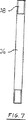
第7図は、第6図の検出管の拡大正面図である。
第8図は、第7図の検出管の側面図である。
第9図は、第7図の検出管の端面図である。
第10図は、傾斜形流れ導管を用いた流量測定装置の形態をなす本発明の別の実施例を示す平面図である。
第11図は、第10図の頂部から下方を見た、第10図の装置の端面図である。
好ましい実施例の説明
図面、より詳しくは第1図に示すように、本発明の好ましい実施例は、ガス源12、制御弁14、圧力センサ16、及びPuritan−Bennett Corporation(カンザス州、Lenexa)から市販されているいわゆるADAM回路に接続されたフローセンサ18(空気ホース20及び鼻枕22を備えている)を有する形式の患者呼吸システム10に使用するのが好ましい。システム10は更に、フエイズ検出回路24及び圧力コントローラ26を有している。好ましい実施例では、コンポーネンツ12〜18及び24〜26は単一ハウジング内に収容され、該ハウジングにADAM回路が接続される。
一般に、ガス源12は、30cm水圧でほぼ120l/分の供給呼吸ガスを作るべく作動する可変速ブロワを有している。圧力センサ16は、Sensym CompanyからModel SCX01として市販されているものが好ましい。フローセンサ18は、Microswitch Corp.から市販されているModel AWM2300Vが好ましく、該フローセンサ18は、該フローセンサを通る空気流(従って、患者に連結された空気回路中の空気流)を表す電気信号を発生すべく作動する変換器を有している。
フエイズ検出回路24は、呼息中に論理高出力を発生し且つ吸息中に論理低出力を発生する。圧力コントローラ26は、フエイズ検出回路24からの出力信号及び圧力センサ16からの出力を受け、これに応答して弁14を作動させ、ガス源12から患者に供給される吸息圧力及び呼息圧力を維持する。
一般譲渡されたSteohen L.Phillipsによる「吸息/呼息フエイズ検出回路(Inhalation/Exhalation Respiratory Phase Detection Circuit)」という名称に係る1993年1月12日付米国特許出願第08/003,129号(該米国特許出願の開示は本願に援用する)には、呼吸システム及びその関連回路についてより詳細に説明されている。
本発明の一実施例によれば、第1図のフローセンサ18は、第2図の流量測定装置32と協働して、ガス源12から弁14を通って患者に至る(及びこの逆)ガスの全流量を検出し且つ測定する。
流量測定装置32は、制御弁14の出力と空気ホース20への入力との間に配置される直円筒状流れ導管34を有している。流れ導管34は、第3図〜第5図に示すようなパイプすなわち管の形態に構成できる。
上流側検出管36は流れ導管34の第1側壁タップを通って流れの中に突出しており、締り嵌めにより所定位置に固定される。検出管36の内端部には半円筒状のノッチ開口38が形成されており、該ノッチ開口38は、流れに直面するようにして流れのほぼ中央に配置される。流れ導管34の外部に延びた検出管36の外端部も同様な端部形状を有している。同一の下流側検出管40が、流れ導管34の第1側壁タップの下流側の第2側壁タップを通って流れの中に延びており且つ締り嵌めにより所定位置に保持される。下流側検出管40の内端部にも同様なノッチ開口42が設けられている。該ノッチ開口42は流れのほぼ中央に配置されるけれども、導管34を通る流れの方向に背を向けて配置される。下流側検出管40の外端部も同様な端部形状を有している。上流側検出管36及び下流側検出管40の外端部のノッチ開口は、それぞれ、上流側及び下流側に対面している。これらの特徴は第2図〜第5図に最も良く示されている。
再び第2図を参照すると、上流側検出管36の外端部は、連結管46を介してフローセンサ/変換器44の入力すなわち高圧側に連結される。フローセンサ/変換器44の出力すなわち低圧側は、別の連結管48を介して下流側検出管40の外端部に連結される。両連結管はシリコーンで作るのが好ましい。この構成により、センサ44及び連結管46、48を通る呼吸ガスの側方流量が形成される。好ましい実施例では、フローセンサ44は、Microswitch Corp.により製造される前述の変換器(Model AWM2300V)である。側方流量は、導管34を通る全流量に比例する。センサ44は、全流量を表す電気信号を発生する。
別の実施例(図示せず)では、フローセンサ44は、Microswitch Corp.のModel 24EFA1D差圧センサのような差圧センサに置換される。差圧センサは、流速に比例(従って、流れ導管34を通るガスの全流量に比例)する圧力降下を測定する。この構成では、連結管46、48を通る側方流は生じない。
両検出管36、40の構造は同一である。上流側検出管36の構造が第6図〜第9図に詳細に示されている。
好ましい実施例では、第6図〜第9図に示すように、検出管36は、好ましくは0.093インチの外径及び0.010インチの壁厚をもつステンレス鋼材料で形成された機械加工管であり、不動態化仕上げが施される。
検出管36の両端部には、矩形の半円筒状ノッチ開口38が形成されている。両ノッチはサイズ及び形状が同一であり且つ同方向に向いている。好ましい実施例では、検出管36は約1.160インチの全長を有し且つ各ノッチは約0.150インチの長さを有し、両ノッチの間に約0.860インチの管が残されている。各ノッチ36の深さは検出管36の直径の1/2より僅かに小さく、すなわち好ましい実施例では約0.046インチである。
特定端部形状は、乱流中に置かれたときに高い抵抗係数が得られるように、従ってこれにより、両検出管36、40間の大きな圧力差及びセンサ44を通る大きな側方流量が得られるように選択される。
流れに対面する上流側ノッチ開口38の場合には、大きな抵抗係数は、流れが検出管36に衝突する高圧力領域を形成する。上流側検出管36はこの流れ領域に開口しており且つ高い圧力をセンサ44の入力側に伝達する。ノッチ開口42の場合には、流れに背を向けて配置され、最大流れ分離(maximum flow separation)はノッチ42の下流側に生じる。この流れ分離は、低圧力領域を創出する。この下流側検出管40はこの領域に開口し且つ低い圧力をセンサ44の出力側に伝達する。センサ入力における高圧とセンサ出力における低圧との組合せにより大きな側方流量が得られ、これにより、センサ44を通る高流量信号が発生される。
半円筒状の形状は、これが上流側に対面するように配向されるか下流側に対面するように配向されるかに基づいて、抵抗係数に大きな差異が生じることが知られている。かくして、第6図〜第9図に示すような検出管36、40の矩形ノッチは大きな圧力差を発生し、これによりセンサ44は最適流れ信号を発生する。
矩形ノッチ形成管(矩形ノッチが形成された管)の寸法的特徴は、導管流れにより発生される差圧に安定性を与え、これにより乱流環境に低雑音信号が発生される。センサ信号(すなわち側方流量)は、ノッチの大きさ、できればノッチの高さ/幅比を変えることにより変えられるけれども、本願明細書に記載する特定の大きさは、本件出願人の下記の特定の呼吸器の用例について最適感度及び範囲を与える。
矩形ノッチ形成管はまた、製造が比較的容易である。上流側検出管36及び下流側検出管40の両者に同一管形状を使用できることは、購入量を経済的にでき且つ潜在的組立て誤差を最小にする。管の両端にノッチが形成されているため、製造方法が簡単になり且つ組立て時にノッチの位置及び方向の視覚確認が行なえる。所望ならば、検出管の外端部のノッチは省略することもできる。
流れ導管34における上流側検出管36と下流側検出管40との間の距離は厳格ではない。しかしながら、両管36、40は、下流側検出管の回りに流れが生じ、これにより流れ分離作用が生じ且つ両管36、40の間に圧力差が生じるように、充分に離離すべきである。
流量測定装置32は乱流の正確な測定を行なうのに特に適したものである。これは、流れの中央に配置したこと及び管のノッチ開口38、42の平均化作用による。
第10図及び第11図には、第2実施例による流量測定装置50が示されている。この流量測定装置50は第2図〜第3図の流量測定装置32と同様であり且つ同様に作動する。第10図及び第11図の装置50は、Puritan−Bennett Companionの320I/E形2レベル呼吸システムに使用するように特別設計されている。
第10図及び第12図に示すように、流量測定装置50は傾斜形流れ導管52を有し、該流れ導管52は、第1円筒状セクション54と、該第1セクション54に対し一定角度をなして配向された第2円筒状セクション56とを備えている。好ましい実施例では、この角度は約14.5゜である。この角度を付す目的は、所望の包囲体内に装置50を適合させることにある。
流量測定装置50は、第6図〜第9図に示し且つ説明した検出管36と同じ構造の上流側検出管58及び下流側検出管60を使用している。上流側検出管58は、第1円筒状セクション54と第2円筒状セクション56との間の結合部で、第1側壁タップを通って延びている。下流側検出管60は、第1円筒状セクション54の第2側壁タップを通って受け入れられている。両検出管58、60の内端部は導管52を通って流れの中に突出している。両検出管58、60の内端部のノッチ開口は流れのほぼ中央に配置され、下流側検出管60はそのノッチ開口が第1円筒状セクション54内で下流側に直面するように配向され、上流側検出管58はそのノッチ開口が第2円筒状セクション56の上流側に直面するように配向されている。両検出管58、60の間の距離は、これらの間に充分な距離があって、流れ分離作用を生じさせ且つ両管36、40の間に圧力差を生じさせる限り厳格ではない。両検出管58、60は、第2図に示した方法と同じ方法で、連結管(図示せず)を介してフローセンサ(図示せず)に連結される。
好ましい用例では、第1円筒状セクション54は、第1図の空気ホース20用出口コネクタとして機能する。第2円筒状セクション56は、弁組立体14の出口ポートへのコネクタとして機能する。
第11図に示すように、第1円筒状セクション54にはまた、下流側検出管60とは反対側に側壁タップ62が設けられている。タップ62の回りのセクション54の外面には、PVC連結管に連結するためのニップルコネクタ64が形成されている。好ましい実施例では、連結管は、圧力センサ16の入口側に連通する圧力管に結合される。この構成を使用すると、流量測定装置50は、第1図の呼吸システムの圧力センサ16及びフローセンサ18の両者への入力を形成する。
以上より、本発明の流量測定装置は、呼吸システムのような乱流環境又は脈流環境における全流量の正確な測定が可能であり、且つ高S/N比での正確な測定が可能である。また、本発明の流量測定装置は、両方向の流れに作動できる対称的設計を与える。
本発明の幾つかの特定形態を例示し且つ説明したが、本発明の精神及び範囲から逸脱することなく種々の変更をなし得ることは明らかである。従って、本発明は、請求の範囲を除き、制限を受けるものではない。 Background of the Invention
FIELD OF THE INVENTION The present invention relates generally to improvements in fluid flow measurement devices, and more particularly to new and improved gas flow measurement in respiratory treatment devices for the treatment of sleep apnea and other respiratory diseases. Relates to the device.
Description of the prior art There are many examples of modern engineering practices required for measuring fluid flow rates. Over the years, various sizes and shapes of tubes have been designed and constructed for this purpose.
The first type of tube used to measure fluid pressure for velocity measurement is invented by Henry Pitot, and the tube for this purpose is often referred to as his Pitot tube. It is out. There are many configurations and geometries of pitot tubes that are compatible with a wide range of applications today.
A typical Pitot tube configuration consists of an open end that is placed in the fluid flow and a sharp upstream portion for measuring stagnation or impact pressure (where the flow velocity is reduced to zero). And one or more side wall taps of the flow conduit for measuring local static pressure in the moving flow. The difference between impact pressure and static pressure is a function of flow velocity.
The upstream disturbance of the fluid flow tends to cause a large error in the flow rate measurement due to the occurrence of turbulence and the influence on the static pressure measurement. A sedation section consisting of at least some tube diameters is often used to obtain accurate measurements. The pulsating flow also adversely affects the flow measurement, and a damping mechanism is sometimes used to eliminate large measurement errors.
Flow measurement devices are commonly used in a wide range of modern medical systems, and one type of such medical system is a respirator used to treat disturbed sleep apnea.
Obstructive sleep apnea is a sleep disorder characterized by relaxation of the airway, including the genioglossus throat muscle, during sleep. When this happens, the relaxed muscles partially or completely occlude the patient's airways. Partial obstruction causes snoring or hypopnea, and complete obstruction causes disturbed sleep apnea.
When a complete occlusion occurs, the patient's inspiratory efforts cannot take in air and the patient is deprived of oxygen. This reaction causes the patient to wake up. When the awake state is almost reached, the hyoid hyoid muscle returns to normal tension, opens the airway, and can inhale. The patient then goes into deeper sleep, after which the crypt hyoid muscle relaxes again and the apnea cycle repeats. As a result, the patient wakes up repeatedly in a nearly awake state and cannot achieve a fully relaxed deep sleep period. People with disturbed sleep apnea symptoms are clearly tired at any time, even after taking a normal nighttime sleep.
In order to treat disturbed sleep apnea, a system of continuous positive airway pressure (CPAP) has been devised, in which a prescribed level of positive airway pressure is continuously applied to the patient's airway. It has come to be added. The presence of such positive pressure imparts a pressure splint on the airway to offset the negative inspiration pressure that draws relaxed airway tissue into an obstruction.
The most preferred device for achieving positive airway coupling is to use a nasal pillow as disclosed in US Pat. No. 4,782,832, incorporated herein by reference. The nasal pillow seals the patient's nostril and applies positive airway pressure through the nasal passage. In addition, the nasal pillow has small through holes for continuously discharging a small amount of air in order to prevent accumulation of carbon dioxide and moisture.
In the CPAP system, the patient must exhale against the prescribed positive pressure. This is uncomfortable for the patient, especially at high pressure levels. Because of this problem, so-called bi-level positive airway pr-essure (BiPAP) systems have been developed in which pressure is reduced during the exhalation phase of the respiratory cycle.
In the BiPAP system, air flow to the patient is measured by a flow measuring device that is pneumatically connected to the nasal pillow. The measuring device is connected to the flow sensor via a transducer that generates an electrical signal representative of the air flow supplied to the patient. The signal is used by an electronic circuit that controls the pressure of the breathing gas delivered to the patient. In addition, a pressure sensor is used to input a signal representing the pressure supplied to the patient into the circuit.
These types of breathing systems generate turbulence and pulsation in the supplied flow of breathing gas. Often, turbulent flow is caused by insufficient space to form a quiescent section returning to laminar flow and laminar flow. Also, under certain conditions, the flow direction itself is reversed, causing problems for the unidirectional flow sensor.
Obviously, accurate measurement of the airflow delivered to the patient is an important feature of the respiratory system. Ideally, the measurement should accurately reflect the dynamics of the two-way flow device and have a high S / N (signal) in both turbulent flow regime and laminar flow characteristics. Should be done in such a way that a (noise to noise) ratio is obtained. The flow measurement should also have a linear characteristic that is proportional to the total flow of the system.
Due to design constraints, it is sometimes necessary to perform flow measurements in a confined space where the total pressure drop can be ignored. It may also be desirable to incorporate the flow measurement device in other parts of the system to reduce the total number of parts. This should be done in a way that facilitates low cost manufacturing ease.
Traditional Pitot tubes used in traditional respiratory designs are right angle tubes with openings arranged in the direction of the incoming flow, and first with an opening arranged back to the flow. Use two right angle tubes. When these two tubes are placed in a conduit containing an air flow, a side flow is created, which leads to the sensor / transducer. The sensor generates a signal that is conditioned to accurately reflect the total flow output of the system.
Although these existing respiratory flow measurement devices can accomplish these purposes, there is still a need for further improvements in these flow measurement devices. More particularly, there is a need for an improved flow measurement device that can provide more accurate and reliable measurements in turbulent or pulsating flow and that operates successfully in both directions. The present invention satisfies all these needs.
SUMMARY OF THE INVENTION Basically, in a broad concept, the present invention provides a new and improved flow measurement apparatus that can accurately and reliably measure fluid flow, particularly fluid flow in turbulent or pulsating conditions. And provides a significant advance in the state of the prior art. More particularly, the device of the present invention reliably measures flow at high signal-to-noise ratios using a symmetrical design that operates in bi-directional flow.
In a preferred embodiment, the present invention provides a flow measurement device that is particularly suitable for measuring airflow in a two-level breathing system. In this application, the present invention provides a flow measurement device that can greatly reduce the effects of disturbance and pulsating flow on the accuracy of flow measurement and can significantly increase the effective S / N ratio.
More particularly, in a preferred embodiment (which is an example and not necessarily limiting the present invention), a flow measuring device embodying various features of the present invention includes a flow conduit, and a protruding and flowing flow in the flow conduit. An upstream detection tube with a notch opening disposed facing the downstream, a downstream detection tube with a notch opening protruding into the flow conduit and facing away from the flow, and an upstream detection tube and downstream A flow sensor / converter arranged in a connecting line with a side detector tube, which represents the side flow through the flow sensor / converter (thus representing the total gas flow in the flow conduit) A flow sensor / converter for generating a signal.
In another embodiment, instead of a flow sensor, a differential pressure sensor / converter is arranged in the connecting line between the upstream detection tube and the downstream detection tube, and the differential pressure sensor / converter allows the flow rate (and thus Measure the pressure drop between both detector tubes proportional to the total air flow delivered through the flow conduit.
Other features and advantages of the present invention will become apparent from the following detailed description, taken in conjunction with the accompanying drawings, illustrating by way of example the features of the invention.
[Brief description of the drawings]
FIG. 1 is a schematic diagram of a one-level or two-level breathing system for performing patient breathing.
FIG. 2 is a schematic diagram of a flow measurement system embodying some of the novel features of the present invention.
FIG. 3 is a perspective view in which a part of the flow conduit, the upstream side detection tube, and the downstream side detection tube of FIG. 2 is broken, and the connecting tube and the flow sensor are omitted for simplification.
FIG. 4 is a side view of the apparatus of FIG.
FIG. 5 is an end view of the apparatus of FIG.
FIG. 6 is an enlarged perspective view of one of the detection tubes of FIG. 3 and has been removed from the flow conduit for simplicity.
FIG. 7 is an enlarged front view of the detection tube of FIG.
FIG. 8 is a side view of the detection tube of FIG.
FIG. 9 is an end view of the detection tube of FIG.
FIG. 10 is a plan view showing another embodiment of the present invention in the form of a flow rate measuring device using an inclined flow conduit.
FIG. 11 is an end view of the apparatus of FIG. 10 as viewed downward from the top of FIG.
Preferred embodiments of the description <br/> drawings, as more particularly shown in FIG. 1, a preferred embodiment of the present invention, the
In general, the
The phase detection circuit 24 produces a logic high output during expiration and a logic low output during inspiration. The
US patent application Ser. No. 08 / 003,129 dated Jan. 12, 1993 under the name “Inhalation / Exhalation Respiratory Phase Detection Circuit” by the commonly assigned Steohen L. Phillips The disclosure of the application is hereby incorporated by reference into the respiratory system and related circuitry in more detail.
According to one embodiment of the present invention, the flow sensor 18 of FIG. 1 cooperates with the
The
The
Referring again to FIG. 2, the outer end of the
In another embodiment (not shown), the
Both
In the preferred embodiment, as shown in FIGS. 6-9, the
A rectangular semi-cylindrical notch opening 38 is formed at both ends of the
The specific end shape provides a high resistance coefficient when placed in turbulent flow, so this provides a large pressure difference between both
In the case of the
It is known that the semi-cylindrical shape has a large difference in resistance coefficient based on whether it is oriented so as to face the upstream side or faced to the downstream side. Thus, the rectangular notches of the
The dimensional characteristics of the rectangular notch tube (the tube with the rectangular notch) provide stability to the differential pressure generated by the conduit flow, thereby generating a low noise signal in a turbulent environment. Although the sensor signal (i.e., lateral flow rate) can be changed by changing the notch size, preferably the notch height / width ratio, the particular magnitude described herein is Gives the optimum sensitivity and range for the various respiratory examples.
Rectangular notch forming tubes are also relatively easy to manufacture. The ability to use the same tube shape for both the
The distance between the
The
FIGS. 10 and 11 show a flow
As shown in FIGS. 10 and 12, the
The flow
In the preferred application, the first
As shown in FIG. 11, the first
As described above, the flow rate measuring device of the present invention can accurately measure the total flow rate in a turbulent flow environment or a pulsating flow environment such as a respiratory system, and can accurately measure at a high S / N ratio. . Also, the flow measurement device of the present invention provides a symmetrical design that can operate in both directions of flow.
While several particular forms of the invention have been illustrated and described, it will be apparent that various modifications can be made without departing from the spirit and scope of the invention. Accordingly, the invention is not limited except as by the appended claims.
Claims (14)
該流れ導管に配置され、流れ流に面するノッチ開口を備えた上流側検出管と、
前記流れ導管に配置され、前記流れ流から遠ざかるように向けられたたノッチ開口を備えた下流側検出管と、
前記上流側検出管及び前記下流側検出管に作動連結された、前記上流側検出管及び前記下流側検出管からの信号を受信するための変換器とを有し、
前記各ノッチ開口が半円筒形状を有する、
流量測定装置。A flow conduit;
An upstream detector tube with a notch opening disposed in the flow conduit and facing the flow flow;
A downstream detector tube with a notch opening disposed in the flow conduit and oriented away from the flow flow;
Said operatively connected to the upstream side detection pipe and the downstream detection tube, possess a converter for receiving a signal from the upstream detecting pipe and the downstream detection tube,
Each notch opening has a semi-cylindrical shape;
Flow measurement device.
該流れ導管内で流れ流に配置されたノッチ開口を備えた検出管と、
該検出管に作動連結された、前記検出管からの信号を受信するための変換器とを有し、
前記ノッチ開口が半円筒形状を有する、
流量測定装置。A flow conduit;
A detector tube with a notch opening disposed in the flow stream within the flow conduit;
Operatively connected on the detected decane, it possesses a converter for receiving a signal from the detecting pipe,
The notch opening has a semi-cylindrical shape;
Flow measurement device.
Applications Claiming Priority (3)
| Application Number | Priority Date | Filing Date | Title |
|---|---|---|---|
| US08/025,045 US5443075A (en) | 1993-03-01 | 1993-03-01 | Flow measuring apparatus |
| US08/025,045 | 1993-03-01 | ||
| PCT/US1994/002215 WO1994020018A1 (en) | 1993-03-01 | 1994-03-01 | Flow measuring apparatus |
Publications (2)
| Publication Number | Publication Date |
|---|---|
| JPH08507379A JPH08507379A (en) | 1996-08-06 |
| JP3595337B2 true JP3595337B2 (en) | 2004-12-02 |
Family
ID=21823747
Family Applications (1)
| Application Number | Title | Priority Date | Filing Date |
|---|---|---|---|
| JP52011494A Expired - Fee Related JP3595337B2 (en) | 1993-03-01 | 1994-03-01 | Flow measuring device |
Country Status (9)
| Country | Link |
|---|---|
| US (1) | US5443075A (en) |
| EP (1) | EP0687161B1 (en) |
| JP (1) | JP3595337B2 (en) |
| AT (1) | ATE341274T1 (en) |
| AU (1) | AU678455B2 (en) |
| CA (1) | CA2157184C (en) |
| DE (1) | DE69434859T2 (en) |
| ES (1) | ES2273331T3 (en) |
| WO (1) | WO1994020018A1 (en) |
Families Citing this family (155)
| Publication number | Priority date | Publication date | Assignee | Title |
|---|---|---|---|---|
| US6675797B1 (en) | 1993-11-05 | 2004-01-13 | Resmed Limited | Determination of patency of the airway |
| EP1900324B1 (en) | 1993-11-05 | 2009-06-03 | ResMed Limited | Apparatus for determining patency of the airway |
| US6237593B1 (en) | 1993-12-03 | 2001-05-29 | Resmed Limited | Estimation of flow and detection of breathing CPAP treatment |
| FI954092A (en) * | 1994-09-08 | 1996-03-09 | Weinmann G Geraete Med | Method of controlling a respirator in the treatment of sleep apnea |
| AUPN236595A0 (en) | 1995-04-11 | 1995-05-11 | Rescare Limited | Monitoring of apneic arousals |
| AUPN394895A0 (en) | 1995-07-03 | 1995-07-27 | Rescare Limited | Auto-calibration of pressure transducer offset |
| AUPN474195A0 (en) * | 1995-08-09 | 1995-08-31 | Rescare Limited | Apparatus and methods for oro-nasal respiration monitoring |
| AUPN547895A0 (en) | 1995-09-15 | 1995-10-12 | Rescare Limited | Flow estimation and compenstion of flow-induced pressure swings cpap treatment |
| EP0862474A4 (en) | 1995-09-18 | 2000-05-03 | Resmed Ltd | Pressure control in cpap treatment or assisted respiration |
| AUPN616795A0 (en) | 1995-10-23 | 1995-11-16 | Rescare Limited | Ipap duration in bilevel cpap or assisted respiration treatment |
| AUPN973596A0 (en) | 1996-05-08 | 1996-05-30 | Resmed Limited | Control of delivery pressure in cpap treatment or assisted respiration |
| US5789660A (en) | 1996-07-15 | 1998-08-04 | Novametrix Medical Systems, Inc. | Multiple function airway adapter |
| AUPO163896A0 (en) | 1996-08-14 | 1996-09-05 | Resmed Limited | Determination of respiratory airflow |
| AUPO247496A0 (en) | 1996-09-23 | 1996-10-17 | Resmed Limited | Assisted ventilation to match patient respiratory need |
| AUPO418696A0 (en) | 1996-12-12 | 1997-01-16 | Resmed Limited | A substance delivery apparatus |
| US5915380A (en) | 1997-03-14 | 1999-06-29 | Nellcor Puritan Bennett Incorporated | System and method for controlling the start up of a patient ventilator |
| AUPO742297A0 (en) | 1997-06-18 | 1997-07-10 | Resmed Limited | An apparatus for supplying breathable gas |
| US5925831A (en) * | 1997-10-18 | 1999-07-20 | Cardiopulmonary Technologies, Inc. | Respiratory air flow sensor |
| AUPP026997A0 (en) * | 1997-11-07 | 1997-12-04 | Resmed Limited | Administration of cpap treatment pressure in presence of apnea |
| USD413825S (en) * | 1998-09-14 | 1999-09-14 | Cardiopulmonary Technologies, Inc. | Respiratory air flow measuring device |
| DE19950237A1 (en) | 1999-10-19 | 2001-06-13 | Glukomeditech Ag | Device for detecting the respiratory nasal flow |
| JP2006504469A (en) * | 2002-11-01 | 2006-02-09 | フィッシャー アンド ペイケル ヘルスケア リミテッド | System for detecting gas delivery to a patient |
| JP4168417B2 (en) | 2002-11-18 | 2008-10-22 | 株式会社山武 | Fluid detection device |
| SE0203427D0 (en) | 2002-11-20 | 2002-11-20 | Siemens Elema Ab | Passive gas sampling device |
| SE0203426D0 (en) * | 2002-11-20 | 2002-11-20 | Siemens Elema Ab | Passive gas sampling device |
| US7878980B2 (en) | 2003-06-13 | 2011-02-01 | Treymed, Inc. | Gas flow diverter for respiratory monitoring device |
| US7588033B2 (en) | 2003-06-18 | 2009-09-15 | Breathe Technologies, Inc. | Methods, systems and devices for improving ventilation in a lung area |
| US7066180B2 (en) * | 2003-07-09 | 2006-06-27 | Airmatrix Technologies, Inc. | Method and system for measuring airflow of nares |
| FR2858236B1 (en) | 2003-07-29 | 2006-04-28 | Airox | DEVICE AND METHOD FOR SUPPLYING RESPIRATORY GAS IN PRESSURE OR VOLUME |
| US7353826B2 (en) * | 2003-08-08 | 2008-04-08 | Cardinal Health 205, Inc. | Sealing nasal cannula |
| JP2007506480A (en) * | 2003-08-18 | 2007-03-22 | ワンドカ,アンソニー・ディ | Methods and apparatus for non-invasive ventilation with a nasal interface |
| FR2875138B1 (en) | 2004-09-15 | 2008-07-11 | Mallinckrodt Dev France Sa | CONTROL METHOD FOR A HEATING HUMIDIFIER |
| DE112005003700A5 (en) * | 2005-07-14 | 2008-06-19 | Systec Controls Mess- Und Regelungstechnik Gmbh | Pitot tube |
| EP1926517A2 (en) | 2005-09-20 | 2008-06-04 | Lutz Freitag | Systems, methods and apparatus for respiratory support of a patient |
| EP1772098B1 (en) * | 2005-10-10 | 2014-02-26 | CareFusion Germany 234 GmbH | Measuring head for diagnostic instruments and method |
| US7640934B2 (en) * | 2005-12-02 | 2010-01-05 | Carefusion 2200, Inc. | Infant nasal interface prong device |
| DE102006011900A1 (en) * | 2006-03-15 | 2007-09-20 | Viasys Healthcare Gmbh | IOS measuring station and IOS measuring method |
| US8021310B2 (en) | 2006-04-21 | 2011-09-20 | Nellcor Puritan Bennett Llc | Work of breathing display for a ventilation system |
| JP5191005B2 (en) | 2006-05-18 | 2013-04-24 | ブリーズ テクノロジーズ, インコーポレイテッド | Method and device for tracheostomy |
| EP2068992B1 (en) | 2006-08-03 | 2016-10-05 | Breathe Technologies, Inc. | Devices for minimally invasive respiratory support |
| US7784461B2 (en) | 2006-09-26 | 2010-08-31 | Nellcor Puritan Bennett Llc | Three-dimensional waveform display for a breathing assistance system |
| US8902568B2 (en) | 2006-09-27 | 2014-12-02 | Covidien Lp | Power supply interface system for a breathing assistance system |
| US20080078390A1 (en) * | 2006-09-29 | 2008-04-03 | Nellcor Puritan Bennett Incorporated | Providing predetermined groups of trending parameters for display in a breathing assistance system |
| EP2081491A4 (en) * | 2006-10-30 | 2010-03-03 | Cha Un Jong | Down-sized single directional respiratory air flow measuring tube |
| WO2008144589A1 (en) | 2007-05-18 | 2008-11-27 | Breathe Technologies, Inc. | Methods and devices for sensing respiration and providing ventilation therapy |
| JP5513392B2 (en) | 2007-09-26 | 2014-06-04 | ブリーズ・テクノロジーズ・インコーポレーテッド | Method and apparatus for treating sleep apnea |
| US8567399B2 (en) | 2007-09-26 | 2013-10-29 | Breathe Technologies, Inc. | Methods and devices for providing inspiratory and expiratory flow relief during ventilation therapy |
| US8640699B2 (en) | 2008-03-27 | 2014-02-04 | Covidien Lp | Breathing assistance systems with lung recruitment maneuvers |
| US8792949B2 (en) | 2008-03-31 | 2014-07-29 | Covidien Lp | Reducing nuisance alarms |
| US8267085B2 (en) | 2009-03-20 | 2012-09-18 | Nellcor Puritan Bennett Llc | Leak-compensated proportional assist ventilation |
| US8746248B2 (en) | 2008-03-31 | 2014-06-10 | Covidien Lp | Determination of patient circuit disconnect in leak-compensated ventilatory support |
| US8425428B2 (en) | 2008-03-31 | 2013-04-23 | Covidien Lp | Nitric oxide measurements in patients using flowfeedback |
| US8272380B2 (en) | 2008-03-31 | 2012-09-25 | Nellcor Puritan Bennett, Llc | Leak-compensated pressure triggering in medical ventilators |
| EP2313138B1 (en) | 2008-03-31 | 2018-09-12 | Covidien LP | System and method for determining ventilator leakage during stable periods within a breath |
| JP5758799B2 (en) | 2008-04-18 | 2015-08-05 | ブリーズ・テクノロジーズ・インコーポレーテッド | Method and device for sensing respiratory effects and controlling ventilator function |
| US8770193B2 (en) | 2008-04-18 | 2014-07-08 | Breathe Technologies, Inc. | Methods and devices for sensing respiration and controlling ventilator functions |
| CN102056539B (en) | 2008-06-06 | 2015-10-07 | 柯惠有限合伙公司 | For making great efforts with patient the system and method that carries out pro rata taking a breath |
| CA2734296C (en) | 2008-08-22 | 2018-12-18 | Breathe Technologies, Inc. | Methods and devices for providing mechanical ventilation with an open airway interface |
| US8528554B2 (en) | 2008-09-04 | 2013-09-10 | Covidien Lp | Inverse sawtooth pressure wave train purging in medical ventilators |
| US8551006B2 (en) | 2008-09-17 | 2013-10-08 | Covidien Lp | Method for determining hemodynamic effects |
| US8424520B2 (en) | 2008-09-23 | 2013-04-23 | Covidien Lp | Safe standby mode for ventilator |
| EP2349420B1 (en) | 2008-09-25 | 2016-08-31 | Covidien LP | Inversion-based feed-forward compensation of inspiratory trigger dynamics in medical ventilators |
| US8181648B2 (en) | 2008-09-26 | 2012-05-22 | Nellcor Puritan Bennett Llc | Systems and methods for managing pressure in a breathing assistance system |
| US8652064B2 (en) | 2008-09-30 | 2014-02-18 | Covidien Lp | Sampling circuit for measuring analytes |
| US8585412B2 (en) | 2008-09-30 | 2013-11-19 | Covidien Lp | Configurable respiratory muscle pressure generator |
| US8439032B2 (en) * | 2008-09-30 | 2013-05-14 | Covidien Lp | Wireless communications for a breathing assistance system |
| US8302602B2 (en) | 2008-09-30 | 2012-11-06 | Nellcor Puritan Bennett Llc | Breathing assistance system with multiple pressure sensors |
| US8302600B2 (en) | 2008-09-30 | 2012-11-06 | Nellcor Puritan Bennett Llc | Battery management for a breathing assistance system |
| US8393323B2 (en) | 2008-09-30 | 2013-03-12 | Covidien Lp | Supplemental gas safety system for a breathing assistance system |
| CA2739435A1 (en) | 2008-10-01 | 2010-04-08 | Breathe Technologies, Inc. | Ventilator with biofeedback monitoring and control for improving patient activity and health |
| US9132250B2 (en) | 2009-09-03 | 2015-09-15 | Breathe Technologies, Inc. | Methods, systems and devices for non-invasive ventilation including a non-sealing ventilation interface with an entrainment port and/or pressure feature |
| WO2010115170A2 (en) | 2009-04-02 | 2010-10-07 | Breathe Technologies, Inc. | Methods, systems and devices for non-invasive open ventilation for treating airway obstructions |
| EP2396062B1 (en) * | 2009-02-11 | 2019-07-24 | ResMed Pty Ltd | Acoustic detection for respiratory treatment apparatus |
| US8434479B2 (en) | 2009-02-27 | 2013-05-07 | Covidien Lp | Flow rate compensation for transient thermal response of hot-wire anemometers |
| US8424521B2 (en) | 2009-02-27 | 2013-04-23 | Covidien Lp | Leak-compensated respiratory mechanics estimation in medical ventilators |
| US8418691B2 (en) | 2009-03-20 | 2013-04-16 | Covidien Lp | Leak-compensated pressure regulated volume control ventilation |
| US9186075B2 (en) * | 2009-03-24 | 2015-11-17 | Covidien Lp | Indicating the accuracy of a physiological parameter |
| US9962512B2 (en) | 2009-04-02 | 2018-05-08 | Breathe Technologies, Inc. | Methods, systems and devices for non-invasive ventilation including a non-sealing ventilation interface with a free space nozzle feature |
| US8776790B2 (en) | 2009-07-16 | 2014-07-15 | Covidien Lp | Wireless, gas flow-powered sensor system for a breathing assistance system |
| US8789529B2 (en) | 2009-08-20 | 2014-07-29 | Covidien Lp | Method for ventilation |
| CA2774902C (en) | 2009-09-03 | 2017-01-03 | Breathe Technologies, Inc. | Methods, systems and devices for non-invasive ventilation including a non-sealing ventilation interface with an entrainment port and/or pressure feature |
| US8439037B2 (en) | 2009-12-01 | 2013-05-14 | Covidien Lp | Exhalation valve assembly with integrated filter and flow sensor |
| US8469030B2 (en) | 2009-12-01 | 2013-06-25 | Covidien Lp | Exhalation valve assembly with selectable contagious/non-contagious latch |
| US8469031B2 (en) | 2009-12-01 | 2013-06-25 | Covidien Lp | Exhalation valve assembly with integrated filter |
| US8439036B2 (en) | 2009-12-01 | 2013-05-14 | Covidien Lp | Exhalation valve assembly with integral flow sensor |
| US8421465B2 (en) | 2009-12-02 | 2013-04-16 | Covidien Lp | Method and apparatus for indicating battery cell status on a battery pack assembly used during mechanical ventilation |
| US8434483B2 (en) | 2009-12-03 | 2013-05-07 | Covidien Lp | Ventilator respiratory gas accumulator with sampling chamber |
| US8677996B2 (en) | 2009-12-04 | 2014-03-25 | Covidien Lp | Ventilation system with system status display including a user interface |
| US8482415B2 (en) | 2009-12-04 | 2013-07-09 | Covidien Lp | Interactive multilevel alarm |
| US8924878B2 (en) | 2009-12-04 | 2014-12-30 | Covidien Lp | Display and access to settings on a ventilator graphical user interface |
| US9119925B2 (en) | 2009-12-04 | 2015-09-01 | Covidien Lp | Quick initiation of respiratory support via a ventilator user interface |
| US9262588B2 (en) | 2009-12-18 | 2016-02-16 | Covidien Lp | Display of respiratory data graphs on a ventilator graphical user interface |
| US8499252B2 (en) | 2009-12-18 | 2013-07-30 | Covidien Lp | Display of respiratory data graphs on a ventilator graphical user interface |
| US8400290B2 (en) | 2010-01-19 | 2013-03-19 | Covidien Lp | Nuisance alarm reduction method for therapeutic parameters |
| US8707952B2 (en) | 2010-02-10 | 2014-04-29 | Covidien Lp | Leak determination in a breathing assistance system |
| US9302061B2 (en) | 2010-02-26 | 2016-04-05 | Covidien Lp | Event-based delay detection and control of networked systems in medical ventilation |
| US8511306B2 (en) | 2010-04-27 | 2013-08-20 | Covidien Lp | Ventilation system with system status display for maintenance and service information |
| US8539949B2 (en) | 2010-04-27 | 2013-09-24 | Covidien Lp | Ventilation system with a two-point perspective view |
| US8453643B2 (en) | 2010-04-27 | 2013-06-04 | Covidien Lp | Ventilation system with system status display for configuration and program information |
| US8638200B2 (en) | 2010-05-07 | 2014-01-28 | Covidien Lp | Ventilator-initiated prompt regarding Auto-PEEP detection during volume ventilation of non-triggering patient |
| US8607788B2 (en) | 2010-06-30 | 2013-12-17 | Covidien Lp | Ventilator-initiated prompt regarding auto-PEEP detection during volume ventilation of triggering patient exhibiting obstructive component |
| US8607789B2 (en) | 2010-06-30 | 2013-12-17 | Covidien Lp | Ventilator-initiated prompt regarding auto-PEEP detection during volume ventilation of non-triggering patient exhibiting obstructive component |
| US8607791B2 (en) | 2010-06-30 | 2013-12-17 | Covidien Lp | Ventilator-initiated prompt regarding auto-PEEP detection during pressure ventilation |
| US8607790B2 (en) | 2010-06-30 | 2013-12-17 | Covidien Lp | Ventilator-initiated prompt regarding auto-PEEP detection during pressure ventilation of patient exhibiting obstructive component |
| US8676285B2 (en) | 2010-07-28 | 2014-03-18 | Covidien Lp | Methods for validating patient identity |
| JP5891226B2 (en) | 2010-08-16 | 2016-03-22 | ブリーズ・テクノロジーズ・インコーポレーテッド | Method, system and apparatus for providing ventilatory assistance using LOX |
| US8554298B2 (en) | 2010-09-21 | 2013-10-08 | Cividien LP | Medical ventilator with integrated oximeter data |
| WO2012045051A1 (en) | 2010-09-30 | 2012-04-05 | Breathe Technologies, Inc. | Methods, systems and devices for humidifying a respiratory tract |
| US8844537B1 (en) | 2010-10-13 | 2014-09-30 | Michael T. Abramson | System and method for alleviating sleep apnea |
| US8757153B2 (en) | 2010-11-29 | 2014-06-24 | Covidien Lp | Ventilator-initiated prompt regarding detection of double triggering during ventilation |
| US8757152B2 (en) | 2010-11-29 | 2014-06-24 | Covidien Lp | Ventilator-initiated prompt regarding detection of double triggering during a volume-control breath type |
| US8595639B2 (en) | 2010-11-29 | 2013-11-26 | Covidien Lp | Ventilator-initiated prompt regarding detection of fluctuations in resistance |
| US8676529B2 (en) | 2011-01-31 | 2014-03-18 | Covidien Lp | Systems and methods for simulation and software testing |
| US8788236B2 (en) | 2011-01-31 | 2014-07-22 | Covidien Lp | Systems and methods for medical device testing |
| US8783250B2 (en) | 2011-02-27 | 2014-07-22 | Covidien Lp | Methods and systems for transitory ventilation support |
| US9038633B2 (en) | 2011-03-02 | 2015-05-26 | Covidien Lp | Ventilator-initiated prompt regarding high delivered tidal volume |
| US8714154B2 (en) | 2011-03-30 | 2014-05-06 | Covidien Lp | Systems and methods for automatic adjustment of ventilator settings |
| US8776792B2 (en) | 2011-04-29 | 2014-07-15 | Covidien Lp | Methods and systems for volume-targeted minimum pressure-control ventilation |
| US9629971B2 (en) | 2011-04-29 | 2017-04-25 | Covidien Lp | Methods and systems for exhalation control and trajectory optimization |
| US9089657B2 (en) | 2011-10-31 | 2015-07-28 | Covidien Lp | Methods and systems for gating user initiated increases in oxygen concentration during ventilation |
| US9364624B2 (en) | 2011-12-07 | 2016-06-14 | Covidien Lp | Methods and systems for adaptive base flow |
| US9498589B2 (en) | 2011-12-31 | 2016-11-22 | Covidien Lp | Methods and systems for adaptive base flow and leak compensation |
| US9022031B2 (en) | 2012-01-31 | 2015-05-05 | Covidien Lp | Using estimated carinal pressure for feedback control of carinal pressure during ventilation |
| US9327089B2 (en) | 2012-03-30 | 2016-05-03 | Covidien Lp | Methods and systems for compensation of tubing related loss effects |
| US8844526B2 (en) | 2012-03-30 | 2014-09-30 | Covidien Lp | Methods and systems for triggering with unknown base flow |
| US9993604B2 (en) | 2012-04-27 | 2018-06-12 | Covidien Lp | Methods and systems for an optimized proportional assist ventilation |
| US9144658B2 (en) | 2012-04-30 | 2015-09-29 | Covidien Lp | Minimizing imposed expiratory resistance of mechanical ventilator by optimizing exhalation valve control |
| US10362967B2 (en) | 2012-07-09 | 2019-07-30 | Covidien Lp | Systems and methods for missed breath detection and indication |
| FR2993783B1 (en) * | 2012-07-26 | 2015-06-05 | Protecsom | INHALATION DEVICE FOR ADMINISTERING DRUG SUBSTANCE DURING INHALATION TREATMENT |
| US9027552B2 (en) | 2012-07-31 | 2015-05-12 | Covidien Lp | Ventilator-initiated prompt or setting regarding detection of asynchrony during ventilation |
| US9375542B2 (en) | 2012-11-08 | 2016-06-28 | Covidien Lp | Systems and methods for monitoring, managing, and/or preventing fatigue during ventilation |
| US9289573B2 (en) | 2012-12-28 | 2016-03-22 | Covidien Lp | Ventilator pressure oscillation filter |
| US9492629B2 (en) | 2013-02-14 | 2016-11-15 | Covidien Lp | Methods and systems for ventilation with unknown exhalation flow and exhalation pressure |
| USD731049S1 (en) | 2013-03-05 | 2015-06-02 | Covidien Lp | EVQ housing of an exhalation module |
| USD693001S1 (en) | 2013-03-08 | 2013-11-05 | Covidien Lp | Neonate expiratory filter assembly of an exhalation module |
| USD701601S1 (en) | 2013-03-08 | 2014-03-25 | Covidien Lp | Condensate vial of an exhalation module |
| USD692556S1 (en) | 2013-03-08 | 2013-10-29 | Covidien Lp | Expiratory filter body of an exhalation module |
| USD744095S1 (en) | 2013-03-08 | 2015-11-24 | Covidien Lp | Exhalation module EVQ internal flow sensor |
| USD731065S1 (en) | 2013-03-08 | 2015-06-02 | Covidien Lp | EVQ pressure sensor filter of an exhalation module |
| USD736905S1 (en) | 2013-03-08 | 2015-08-18 | Covidien Lp | Exhalation module EVQ housing |
| USD731048S1 (en) | 2013-03-08 | 2015-06-02 | Covidien Lp | EVQ diaphragm of an exhalation module |
| US9358355B2 (en) | 2013-03-11 | 2016-06-07 | Covidien Lp | Methods and systems for managing a patient move |
| US9981096B2 (en) | 2013-03-13 | 2018-05-29 | Covidien Lp | Methods and systems for triggering with unknown inspiratory flow |
| US9950135B2 (en) | 2013-03-15 | 2018-04-24 | Covidien Lp | Maintaining an exhalation valve sensor assembly |
| US10064583B2 (en) | 2013-08-07 | 2018-09-04 | Covidien Lp | Detection of expiratory airflow limitation in ventilated patient |
| US9675771B2 (en) | 2013-10-18 | 2017-06-13 | Covidien Lp | Methods and systems for leak estimation |
| US9808591B2 (en) | 2014-08-15 | 2017-11-07 | Covidien Lp | Methods and systems for breath delivery synchronization |
| US9950129B2 (en) | 2014-10-27 | 2018-04-24 | Covidien Lp | Ventilation triggering using change-point detection |
| US9925346B2 (en) | 2015-01-20 | 2018-03-27 | Covidien Lp | Systems and methods for ventilation with unknown exhalation flow |
| USD775345S1 (en) | 2015-04-10 | 2016-12-27 | Covidien Lp | Ventilator console |
| US10765822B2 (en) | 2016-04-18 | 2020-09-08 | Covidien Lp | Endotracheal tube extubation detection |
| US20180042409A1 (en) * | 2016-08-10 | 2018-02-15 | Mark R. Johnson | Ventilated pillow |
| US20190099576A1 (en) * | 2016-12-05 | 2019-04-04 | Medipines Corporation | Breathing tube assembly for respiratory gas measurement for steady-state breathing |
| US10792449B2 (en) | 2017-10-03 | 2020-10-06 | Breathe Technologies, Inc. | Patient interface with integrated jet pump |
| US10668239B2 (en) | 2017-11-14 | 2020-06-02 | Covidien Lp | Systems and methods for drive pressure spontaneous ventilation |
Family Cites Families (6)
| Publication number | Priority date | Publication date | Assignee | Title |
|---|---|---|---|---|
| US3312106A (en) * | 1964-12-07 | 1967-04-04 | Davis Merlin | Flow meter |
| US4047521A (en) * | 1975-11-04 | 1977-09-13 | Carl Kramer | Rate-of-flow meter, particularly for diagnostic spirometry |
| US4896541A (en) * | 1979-05-21 | 1990-01-30 | Vortran Corporation | Vortex generating mass flowmeter |
| FR2457675A1 (en) * | 1979-05-29 | 1980-12-26 | Research Dev Corp | PITOT TUBE PNEUMOTACHOGRAPHER |
| SU888937A1 (en) * | 1979-12-28 | 1981-12-15 | Всесоюзный Научно-Исследовательский Институт Медицинского Приборостроения | Pneumotachograph |
| DE3038180A1 (en) * | 1980-10-09 | 1982-05-27 | IWK Regler und Kompensatoren GmbH, 7513 Stutensee | DEVICE FOR MEASURING DIFFERENTIAL PRESSURE |
-
1993
- 1993-03-01 US US08/025,045 patent/US5443075A/en not_active Expired - Lifetime
-
1994
- 1994-03-01 CA CA002157184A patent/CA2157184C/en not_active Expired - Lifetime
- 1994-03-01 WO PCT/US1994/002215 patent/WO1994020018A1/en active IP Right Grant
- 1994-03-01 JP JP52011494A patent/JP3595337B2/en not_active Expired - Fee Related
- 1994-03-01 AT AT94910798T patent/ATE341274T1/en not_active IP Right Cessation
- 1994-03-01 ES ES94910798T patent/ES2273331T3/en not_active Expired - Lifetime
- 1994-03-01 AU AU63565/94A patent/AU678455B2/en not_active Ceased
- 1994-03-01 DE DE69434859T patent/DE69434859T2/en not_active Expired - Lifetime
- 1994-03-01 EP EP94910798A patent/EP0687161B1/en not_active Expired - Lifetime
Also Published As
| Publication number | Publication date |
|---|---|
| ATE341274T1 (en) | 2006-10-15 |
| EP0687161A4 (en) | 1998-10-21 |
| ES2273331T3 (en) | 2007-05-01 |
| EP0687161A1 (en) | 1995-12-20 |
| WO1994020018A1 (en) | 1994-09-15 |
| AU678455B2 (en) | 1997-05-29 |
| EP0687161B1 (en) | 2006-10-04 |
| US5443075A (en) | 1995-08-22 |
| DE69434859T2 (en) | 2007-03-08 |
| DE69434859D1 (en) | 2006-11-16 |
| CA2157184C (en) | 2004-09-21 |
| JPH08507379A (en) | 1996-08-06 |
| AU6356594A (en) | 1994-09-26 |
| CA2157184A1 (en) | 1994-09-15 |
Similar Documents
| Publication | Publication Date | Title |
|---|---|---|
| JP3595337B2 (en) | Flow measuring device | |
| US9713438B2 (en) | Flow sensor | |
| AU2002347264B2 (en) | A nasal and oral cannula apnea detection device | |
| US5535633A (en) | Differential pressure sensor for respiratory monitoring | |
| US8652065B2 (en) | Breathing transition detection | |
| US6397841B1 (en) | Apparatus for supplying breathable gas | |
| US6253766B1 (en) | Continuous positive airway pressure therapy device | |
| US20100113956A1 (en) | Nasal cannula for acquiring breathing information | |
| US7172557B1 (en) | Spirometer, display and method | |
| WO2002089885A3 (en) | Device for artificial respiration with an endotracheal tube | |
| AU2002347264A1 (en) | A nasal and oral cannula apnea detection device | |
| EP1228779A1 (en) | Method and apparatus for determining a zero gas flow state in a bidirectional gas flow conduit | |
| JP2014508595A (en) | Device for tracking adherence to treatment of obstructive sleep apnea | |
| CN107847705A (en) | Nose equipment | |
| WO1996018338A1 (en) | Internal registration of gas/air - and other fluid flows in a human body and use of pressure sensors for such registration | |
| US20050109122A1 (en) | Respiratory flow sensor | |
| JP2002136595A (en) | Flowmeter for respirator | |
| EP2720005B1 (en) | Arrangement for a pressure measurement of a breathing gas flowing along a flow channel | |
| Eisenkraft et al. | Monitoring pressure, volume, and flow in the anesthesia breathing system | |
| JP2668004B2 (en) | Ventilator flow detection device and ventilator | |
| Wilder et al. | Evaluation in animals of a system to estimate tracheal pressure from the endotracheal tube cuff | |
| DE3539719A1 (en) | Breathing monitor for artificially ventilated and spontaneously breathing premature or newly born babies and infants | |
| TW201434439A (en) | Gas flow detector and positive airway pressure apparatus containing the same |
Legal Events
| Date | Code | Title | Description |
|---|---|---|---|
| A601 | Written request for extension of time |
Free format text: JAPANESE INTERMEDIATE CODE: A601 Effective date: 20040413 |
|
| A602 | Written permission of extension of time |
Free format text: JAPANESE INTERMEDIATE CODE: A602 Effective date: 20040607 |
|
| A521 | Request for written amendment filed |
Free format text: JAPANESE INTERMEDIATE CODE: A523 Effective date: 20040707 |
|
| TRDD | Decision of grant or rejection written | ||
| A01 | Written decision to grant a patent or to grant a registration (utility model) |
Free format text: JAPANESE INTERMEDIATE CODE: A01 Effective date: 20040824 |
|
| A61 | First payment of annual fees (during grant procedure) |
Free format text: JAPANESE INTERMEDIATE CODE: A61 Effective date: 20040903 |
|
| R150 | Certificate of patent or registration of utility model |
Free format text: JAPANESE INTERMEDIATE CODE: R150 |
|
| FPAY | Renewal fee payment (event date is renewal date of database) |
Free format text: PAYMENT UNTIL: 20080910 Year of fee payment: 4 |
|
| FPAY | Renewal fee payment (event date is renewal date of database) |
Free format text: PAYMENT UNTIL: 20090910 Year of fee payment: 5 |
|
| FPAY | Renewal fee payment (event date is renewal date of database) |
Free format text: PAYMENT UNTIL: 20100910 Year of fee payment: 6 |
|
| FPAY | Renewal fee payment (event date is renewal date of database) |
Free format text: PAYMENT UNTIL: 20110910 Year of fee payment: 7 |
|
| FPAY | Renewal fee payment (event date is renewal date of database) |
Free format text: PAYMENT UNTIL: 20110910 Year of fee payment: 7 |
|
| FPAY | Renewal fee payment (event date is renewal date of database) |
Free format text: PAYMENT UNTIL: 20120910 Year of fee payment: 8 |
|
| LAPS | Cancellation because of no payment of annual fees |