JP3594635B2 - Geothermal power plant operating on high pressure geothermal fluid - Google Patents
Geothermal power plant operating on high pressure geothermal fluid Download PDFInfo
- Publication number
- JP3594635B2 JP3594635B2 JP24775893A JP24775893A JP3594635B2 JP 3594635 B2 JP3594635 B2 JP 3594635B2 JP 24775893 A JP24775893 A JP 24775893A JP 24775893 A JP24775893 A JP 24775893A JP 3594635 B2 JP3594635 B2 JP 3594635B2
- Authority
- JP
- Japan
- Prior art keywords
- power plant
- steam
- cooler
- pressure
- liquid
- Prior art date
- Legal status (The legal status is an assumption and is not a legal conclusion. Google has not performed a legal analysis and makes no representation as to the accuracy of the status listed.)
- Expired - Lifetime
Links
- 239000012530 fluid Substances 0.000 title claims description 53
- 239000007788 liquid Substances 0.000 claims description 47
- 239000006200 vaporizer Substances 0.000 claims description 30
- 238000000926 separation method Methods 0.000 claims description 17
- 230000005611 electricity Effects 0.000 claims description 11
- 239000002699 waste material Substances 0.000 claims description 11
- 230000004044 response Effects 0.000 claims description 8
- 230000008878 coupling Effects 0.000 claims description 6
- 238000010168 coupling process Methods 0.000 claims description 6
- 238000005859 coupling reaction Methods 0.000 claims description 6
- 230000006837 decompression Effects 0.000 claims description 6
- 238000010438 heat treatment Methods 0.000 claims description 5
- 230000007246 mechanism Effects 0.000 claims description 5
- 238000012545 processing Methods 0.000 claims description 3
- 230000005855 radiation Effects 0.000 claims description 3
- 230000008016 vaporization Effects 0.000 claims description 2
- 238000001704 evaporation Methods 0.000 claims 2
- 230000017525 heat dissipation Effects 0.000 claims 1
- 238000002347 injection Methods 0.000 claims 1
- 239000007924 injection Substances 0.000 claims 1
- XLYOFNOQVPJJNP-UHFFFAOYSA-N water Substances O XLYOFNOQVPJJNP-UHFFFAOYSA-N 0.000 description 15
- 150000003839 salts Chemical class 0.000 description 9
- 229920006395 saturated elastomer Polymers 0.000 description 8
- 239000012267 brine Substances 0.000 description 7
- HPALAKNZSZLMCH-UHFFFAOYSA-M sodium;chloride;hydrate Chemical compound O.[Na+].[Cl-] HPALAKNZSZLMCH-UHFFFAOYSA-M 0.000 description 7
- 238000010586 diagram Methods 0.000 description 5
- FAPWRFPIFSIZLT-UHFFFAOYSA-M Sodium chloride Chemical compound [Na+].[Cl-] FAPWRFPIFSIZLT-UHFFFAOYSA-M 0.000 description 4
- 238000012423 maintenance Methods 0.000 description 4
- 238000000034 method Methods 0.000 description 4
- 239000011780 sodium chloride Substances 0.000 description 4
- 238000007689 inspection Methods 0.000 description 3
- 239000000203 mixture Substances 0.000 description 3
- 230000008569 process Effects 0.000 description 3
- OFBQJSOFQDEBGM-UHFFFAOYSA-N Pentane Chemical compound CCCCC OFBQJSOFQDEBGM-UHFFFAOYSA-N 0.000 description 2
- 238000009833 condensation Methods 0.000 description 2
- 230000005494 condensation Effects 0.000 description 2
- 239000000110 cooling liquid Substances 0.000 description 2
- QWTDNUCVQCZILF-UHFFFAOYSA-N isopentane Chemical compound CCC(C)C QWTDNUCVQCZILF-UHFFFAOYSA-N 0.000 description 2
- 230000004048 modification Effects 0.000 description 2
- 238000012986 modification Methods 0.000 description 2
- 239000002244 precipitate Substances 0.000 description 2
- 230000009467 reduction Effects 0.000 description 2
- 230000009471 action Effects 0.000 description 1
- 230000015572 biosynthetic process Effects 0.000 description 1
- 238000001816 cooling Methods 0.000 description 1
- AFABGHUZZDYHJO-UHFFFAOYSA-N dimethyl butane Natural products CCCC(C)C AFABGHUZZDYHJO-UHFFFAOYSA-N 0.000 description 1
- 238000001035 drying Methods 0.000 description 1
- 230000000737 periodic effect Effects 0.000 description 1
- 238000001556 precipitation Methods 0.000 description 1
- 238000002360 preparation method Methods 0.000 description 1
- 238000005086 pumping Methods 0.000 description 1
- 238000012546 transfer Methods 0.000 description 1
Images

Classifications
-
- F—MECHANICAL ENGINEERING; LIGHTING; HEATING; WEAPONS; BLASTING
- F01—MACHINES OR ENGINES IN GENERAL; ENGINE PLANTS IN GENERAL; STEAM ENGINES
- F01K—STEAM ENGINE PLANTS; STEAM ACCUMULATORS; ENGINE PLANTS NOT OTHERWISE PROVIDED FOR; ENGINES USING SPECIAL WORKING FLUIDS OR CYCLES
- F01K23/00—Plants characterised by more than one engine delivering power external to the plant, the engines being driven by different fluids
- F01K23/02—Plants characterised by more than one engine delivering power external to the plant, the engines being driven by different fluids the engine cycles being thermally coupled
- F01K23/04—Plants characterised by more than one engine delivering power external to the plant, the engines being driven by different fluids the engine cycles being thermally coupled condensation heat from one cycle heating the fluid in another cycle
-
- F—MECHANICAL ENGINEERING; LIGHTING; HEATING; WEAPONS; BLASTING
- F03—MACHINES OR ENGINES FOR LIQUIDS; WIND, SPRING, OR WEIGHT MOTORS; PRODUCING MECHANICAL POWER OR A REACTIVE PROPULSIVE THRUST, NOT OTHERWISE PROVIDED FOR
- F03G—SPRING, WEIGHT, INERTIA OR LIKE MOTORS; MECHANICAL-POWER PRODUCING DEVICES OR MECHANISMS, NOT OTHERWISE PROVIDED FOR OR USING ENERGY SOURCES NOT OTHERWISE PROVIDED FOR
- F03G4/00—Devices for producing mechanical power from geothermal energy
- F03G4/074—Safety arrangements
-
- F—MECHANICAL ENGINEERING; LIGHTING; HEATING; WEAPONS; BLASTING
- F24—HEATING; RANGES; VENTILATING
- F24T—GEOTHERMAL COLLECTORS; GEOTHERMAL SYSTEMS
- F24T10/00—Geothermal collectors
- F24T10/20—Geothermal collectors using underground water as working fluid; using working fluid injected directly into the ground, e.g. using injection wells and recovery wells
-
- Y—GENERAL TAGGING OF NEW TECHNOLOGICAL DEVELOPMENTS; GENERAL TAGGING OF CROSS-SECTIONAL TECHNOLOGIES SPANNING OVER SEVERAL SECTIONS OF THE IPC; TECHNICAL SUBJECTS COVERED BY FORMER USPC CROSS-REFERENCE ART COLLECTIONS [XRACs] AND DIGESTS
- Y02—TECHNOLOGIES OR APPLICATIONS FOR MITIGATION OR ADAPTATION AGAINST CLIMATE CHANGE
- Y02E—REDUCTION OF GREENHOUSE GAS [GHG] EMISSIONS, RELATED TO ENERGY GENERATION, TRANSMISSION OR DISTRIBUTION
- Y02E10/00—Energy generation through renewable energy sources
- Y02E10/10—Geothermal energy
Landscapes
- Engineering & Computer Science (AREA)
- Chemical & Material Sciences (AREA)
- Combustion & Propulsion (AREA)
- Life Sciences & Earth Sciences (AREA)
- Mechanical Engineering (AREA)
- General Engineering & Computer Science (AREA)
- Sustainable Energy (AREA)
- Hydrology & Water Resources (AREA)
- Sustainable Development (AREA)
- Engine Equipment That Uses Special Cycles (AREA)
Description
【0001】
【産業上の利用分野】
本発明は高圧地熱流体に対して動作する地熱電力プラントに関する。
【0002】
【従来の技術】
現在研究開発されている多くの地熱源は150psia程度の圧力で熱塩水を大量に生じており、このうちの幾つかの地熱源では、例えば、800psiaの高圧で蒸気と塩水の混合流体が生じる。そして、後者のような場合、塩水は通常きわめて腐食性が高く、このような塩水を使用し取り扱う場合に種々の問題が発生する。例えば、最近ハワイに地熱井が掘られて、約80%の蒸気と20%の塩水とを含む高圧流体が取り出されているが、この蒸気は、通常、飽和蒸気のみであり、このような井戸が、多年にわたる連続的な使用において、800psiaもの圧力を維持し得るかどうかという問題が生じている。
【0003】
このような不確実性に対処するために、当該井戸から得られる流体に減圧弁を備えて、上述のような高い圧力を減少し得る低圧蒸気システムを使用することが従来から行われている。しかしながら、このような従来の構成は、プラントの寿命や損失する電力量の点で、コスト高であり、不効率である。
【0004】
そこで、発電機を駆動する背圧蒸気タービンが、井戸から得られる高圧蒸気をタービンにより低圧蒸気に変換できる点や、低圧蒸気により動作可能な多くのモジュールに同時に供給できる点で、この代替法として考えられている。この場合、各モジュールは低圧蒸気ターボジェネレータや有機蒸気ターボジェネレータ用の気化器として作用する冷却器を利用することができる。しかしながら、当該地熱流体が高圧の飽和蒸気のみを生成すると、タービン内の蒸気の膨張が温度−エントロピー図の湿潤領域において起こるため、水滴を含む水蒸気が放出されて、種々のモジュール内の低圧蒸気タービンにおける投入ステージへの供給に適さなくなる。
【0005】
【発明が解決しようとする課題】
したがって、本発明の目的は、上述の従来技術における不都合を伴うことなく、高圧地熱流体に対して動作可能な新規の改良された地熱電力プラントを提供することである。
【0006】
【課題を解決するための手段】
本発明によれば、高圧地熱流体を使用する地熱電力プラントは、地熱流体を、高圧蒸気を含む経路と高圧液体を含む経路から成る二つの経路に分離する第1分離装置を含む。高圧蒸気は、発電しかつ相当量の水分を含有する放熱処理された高圧排出蒸気を生成するための第1タービン中において膨張する。このように放熱処理された高圧蒸気は、前記排出蒸気を蒸気成分と液体成分とに分離する第2分離装置に供給される。さらに、上記第1分離装置により生成された高圧液体は第1熱交換器に供給され、これとともに、前記熱交換器には、蒸気成分に対する熱移動を行うために、第2分離装置から蒸気成分が供給される。すなわち、第1熱交換器は、蒸気成分を乾燥し、かつ、可能な限り過熱して、低圧で乾燥飽和していて可能な限り過熱された蒸気と冷却された高圧液体とを生じるべく作用する。
【0007】
この場合、少なくとも一つの電力プラントモジュールが、低圧蒸気に応じて電気を生じ、かつ、有機性流体を含む冷却器/気化器に供給される放熱された低圧蒸気に応じて動作する低圧蒸気タービンを含んだ状態で、付設されている。冷却器/気化器においては、放熱された低圧蒸気は有機性流体の気化にともなって凝縮液となる。その後、気化した有機性流体は有機性蒸気タービンに供給され、タービンは電気を発生し、かつ、放熱した有機性蒸気を生成する。さらに、当該放熱した有機性蒸気は冷却器により液体に凝縮され、当該液体はポンプ処理により上記の冷却器/気化器に予熱器を介して帰還する。また、有機蒸気冷却器からの凝縮液も予熱器に移されて冷却され、その後、廃棄井戸に廃棄される。
【0008】
なお、上記第1分離装置により生成した高圧液体は通常腐食性が強くたいていの用途において使用することができないが、第1熱交換器においては、各モジュールの蒸気タービンにおいて使用するために上記第2分離装置により生成される蒸気成分を乾燥し、かつ、可能な限り過熱する目的のために使用することができる。さらに、モジュール中の上記冷却器/気化器により生成した凝縮液は相当量の熱を含有しており、廃棄井戸に直接転送するのではなく、予熱処理のために利用することができる。
【0009】
また、この種の複数のモジュールを利用すると、上記の低圧蒸気をモジュールの各々における蒸気タービンに平行に供給できる。この場合、第2分離装置からの凝縮液は上記高圧蒸気タービンの排出温度に相当する温度となるため、これもまた予熱処理の目的で使用することができる。この結果、第2分離装置により生成される液体成分を各モジュールの予熱装置に平行に供給することができる。
【0010】
【実施例】
以下、図面に基づいて本発明の実施例を説明する。
【0011】
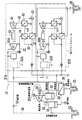
図1において、参照符号10は高圧地熱流体に対して動作する本発明に基づく地熱電力プラントを示している。この地熱流体は供給井戸12から供給され、通常は、約80%の飽和蒸気と20%の塩水の混合体から成る約800psiaの圧力の地熱流体を生成する。このようにして井戸12により生成された流体組成物はまず第1分離装置14に供給され、当該分離装置で二つの経路、すなわち、参照符号15で示される蒸気を含む経路と、参照符号16により示される高圧液体を含む経路とに分離される。その後、経路15における高圧の飽和蒸気は、高圧蒸気タービン18に供給される。なお、タービン18は発電器19に直接連結されており、タービン18における高圧蒸気の膨張により発電器19が駆動して、電気グリッド(図示せず)に供給されるべき電気が発生するようになっている。
【0012】
高圧放熱蒸気はタービン18から参照符号20に示すように排出されて第2分離装置21に供給され、ここで蒸気成分と液体成分とに分離することができる。この場合、蒸気成分は参照符号27A、27B等で示される複数の電力プラントモジュールの各々に平行に供給される。また、配管20を介してタービン18から排出された高圧の放熱蒸気は導管22を介して第1熱交換器23に送られる。なお、熱交換器23には配管16中の高圧液体も供給される。第1熱交換器23における熱交換処理では、ウェルヘッド部における温度及び圧力を有する高圧液体が冷却されて、導管24を介して廃棄井戸25に送られる。この際、この高圧液体に含まれる熱が配管22中の蒸気成分に移って蒸気成分を過熱し、低圧の乾燥蒸気を生成する。その後、低圧蒸気は導管26を介して参照符号27A、27B等で示される複数の電力プラントモジュールの各々に平行に供給される。
【0013】
すなわち、導管26中の低圧乾燥飽和蒸気若しくは過熱処理された蒸気は電力プラントモジュール27A、27B等の蒸気タービン30A、30B等の各投入ステージに供給される。図1においては二つのモジュールのみが示されているが、実際には、10個またはそれ以上の数のモジュールを使用することを企図している。ここでは、本発明の説明を簡単にするために、モジュール27Aについてのみ詳述する。
【0014】
蒸気タービン30Aの投入ステージに供給された低圧蒸気は当該タービン中において膨張し、当該蒸気エネルギーの一部が蒸気タービン30Aと発電器32との間の連結により電気に変換される際に、放熱した低圧蒸気を生成する。その後、タービン30Aから排出された放熱低圧蒸気は冷却器/気化器34に供給されて凝縮され、配管35中に凝縮液を生成する。この凝縮液は、好ましくは第2分離装置21により生成された液体成分の一部とともに、電力プラントモジュールの予熱器37に供給される。このようにして、凝縮液と好ましくは液体成分とが当該予熱器において放熱した後、冷却された液体は混合されて廃棄井戸38に廃棄される。
【0015】
上記の冷却器/気化器34は、周囲の諸条件に従って、有機性の流体、好ましくはペンタン若しくはイソペンタン、を含んでおり、当該流体は冷却器の一方の側において上記低圧蒸気の凝縮により気化する。その後、このようにして冷却器/気化器により生成された有機性流体の蒸気は有機性蒸気タービン40に供給されて膨張し、放熱した有機性蒸気が配管41中に生成されるとともに、有機性蒸気タービン40が発電器32を駆動する。
【0016】
次いで、冷却器42がタービン40から排出された有機性の放熱蒸気を受け取り、冷却器42中の冷却液によって、当該有機性放熱蒸気が凝縮されて液体となる。この有機性液体はポンプ43の作用により予熱器37を介して上記冷却器/気化器34に戻され、冷却器/気化器34に供給される前に予熱される。なお、冷却器42中の冷却液は空気若しくは水などの液体でよい。
【0017】
さらに、当該モジュール27Aの蒸気タービン30Aにはバイパス配管31が取り付けられており、モジュールの有機蒸気タービン40の動作に支障を来すことなく、蒸気タービン30Aを保守点検のために取り出すことを可能にしている。
【0018】
図1は二つの廃棄井戸、すなわち井戸25と38を示しているが、単一の廃棄井戸を用いることも可能である。このような構成は、当該電力プラントの配管24における冷却された液体が冷却処理中に沈澱を生じ得るような場合に特に望ましい。すなわち、このような場合には、電力プラントモジュールの予熱器37により生成されたほとんど純粋な水が、塩水を希釈するために、配管24中の冷却された液体と混合することができるので、当該冷却された液体を廃棄井戸に移送する間に沈澱の発生を阻止することができる。
【0019】
保守点検と供給井戸12により生成される地熱源流体の圧力および温度の偶然の減少に備えるべく、図1に示す地熱電力プラントの動作に融通性を付与するために、タービン18はバイパス配管50によりバイパス処理されており、当該供給井戸12からの地熱流体が各電力プラントモジュールの分離装置52A、52Bに直接供給されるようになっている。また、井戸12の高圧に対処するために、配管50中の減圧装置53が使用される。したがって、電力プラントモジュール27Aにおける分離装置52Aに供給される地熱流体の圧力は当該モジュールの蒸気タービン30Aに対応する投入口側動作圧力と同一である。
【0020】
配管50の動作時には、蒸気タービン18が閉じて分離装置14が不動作状態になる。その結果、配管26は低圧の蒸気を何ら送通しなくなる。一方、分離装置52Aおよび52Bは、第1分離装置14が蒸気タービン18と連携して機能するのと同様に、地熱流体を二つの蒸気流に分割する。従って、低圧蒸気が分離装置52Aから蒸気タービン30Aに供給される。
【0021】
各モジュールの主要部分は前述の如く動作するが、通常、冷却器/気化器により生成される凝縮液のみが予熱器37に利用できる。たいていの場合、配管50における地熱流体の塩水成分は濃縮されかつ腐食性が高いため、これを予熱器に適用することは実用的でないと考えられている。しかしながら、適当な諸条件下においては、当該塩水成分を予熱器に供給することが可能であり、冷却器/気化器により生成された凝縮液が塩水を希釈して予熱器中の沈澱の発生を回避する。
【0022】
上述の如く、バイパス配管50を実際のプラント中に備えることにより、蒸気タービン18の保守点検中の動作に関する融通性が得られる。したがって、バイパス配管を開放にしてタービンを動作系統から取り出せば、当該電力プラントモジュールの動作を続行しかつオンラインの状態に保つことができる。それゆえ、この電力プラントより取得できる全電力は発電器19をオフラインとすることにより減少するが、電力プラントは相当量の電気を依然として生成することが可能である。勿論、当該電力プラントのモジュール上の特性により、電力プラントの出力の減少を小さなものに押さえたまま、モジュール27A、27B等を保守点検のためにラインから個々に取り外すことが可能である。
【0023】
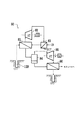
図2は、モジュール中の発電器32と蒸気タービン30Aおよび有機性蒸気タービン40との好ましい連結状態を示している。すなわち、この好ましい配列構成においては、フォルクディスク(Falk disc)連結機構が各タービン30Aおよび40の出力軸に参照符号60に示す如く固着されている。他方、図2の参照符号61により示すように、発電器32の対向出力軸には同種の連結機構が付設されている。これらの連結機構の間には減速ギアユニット62(Lufkin社製)が配され、発電器32がこれらのタービンの回転速度よりも幾分遅い速度で動作するようになっている。
【0024】
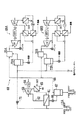
図3は図1に示す実施例の一変更態様を示しており、ここでは、閉じた動作サイクル型の高圧蒸気タービンが、図1の開放した動作サイクル型の蒸気タービンの代わりに用いられている。図3の電力プラント60においては、供給井戸12Aからの高圧地熱流体が熱交換器61に送り込まれて、水との熱交換処理により、配管62中に蒸気が生成され、さらに、蒸気は蒸気タービン63に供給されて発電器64を駆動する。その後、タービン63から排出された放熱蒸気が冷却器65に供給されて凝縮処理が行われた後、凝縮液がポンプ(図示せず)を介して熱交換器61に帰還する。この場合、冷却器65は水冷式でも空冷式でもよい。
【0025】
熱交換器61に存する地熱流体は蒸気と塩水との混合流体となり、井戸12Aからの塩水よりは冷却されているが、その圧力は比較的高い。この圧力は、図1に示す実施例における供給源からの塩水に対して動作する減圧装置53と多分に同様に、減圧装置66において減少される。このようにして圧力が減少された後、流体は分離装置67に送られ、蒸気の部分が液体の部分から分離される。なお、蒸気は実質的に飽和しており、導管68を介してモジュール69A、69B等に送られる。これらのモジュールは前述のモジュール27A、27B等と同等である。
【0026】
モジュール69A、69B等のデミスター70A、70B等は、蒸気がこれらモジュールの蒸気タービンに供給される前に、蒸気中の水分を分離するべく作用する。その後、これらモジュール中の蒸気タービンから排出された蒸気は、上述のモジュールの場合と同様に有機性蒸気タービンに供給された有機性流体を気化するための冷却器/気化器に供給される。さらに、図3に示すモジュールにおける冷却器/気化器からの蒸気の凝縮液もまた図1の場合と同様に予熱処理に利用される。加えて、減圧装置66に存する流体は分離装置72Aおよび72Bに平行に直接供給することができる。
【0027】
さらに、電力プラント60には、図1のものと同様のタービン63のバイパスが付設されている。すなわち、減圧装置71は、各モジュールの分離装置72A、72Bに供給井戸12Aから塩水を直接供給するべく、高圧塩水を熱交換器61に対して選択的にバイパス処理することができる。これらの分離装置は流体の流れを蒸気経路と液体経路とに分離し、次いで、各モジュールの蒸気経路は当該モジュールの蒸気タービンに蒸気を供給する。一方、液体経路は相当の熱量を有している井戸12Aから供給された塩水を含んでおり、当該塩水は、各モジュールの冷却器/気化器により生成され、かつ、それらの予熱器に供給された凝縮蒸気と混合することができる。したがって、タービン63、あるいは、これに付属する部品のいずれかが定期的な点検のために閉塞されると、バイパス減圧装置71が開放されて各モジュールをオンライン状態にする。
【0028】
図4は本発明のさらに他の実施例を示しており、当該実施例は、図3に示すような閉じた動作サイクルの高圧蒸気タービンが使用され、さらに、減圧装置の代わりに図1に示すような蒸気タービンが使用されている点で、図1および図3の実施例の組み合わせと考えられる。図4に示すように、実施例80は供給井戸12Bからの高圧塩水を受け取る高圧熱交換器81を含む。この塩水の熱は水と交換されて、高圧蒸気タービン82に供給されて発電器83を駆動するための蒸気を生成する。また、タービン82により生成された放熱蒸気は冷却器83に供給されて凝縮され、この凝縮液はポンプ(図示せず)を介して熱交換器81に帰還する。
【0029】
さらに、熱交換器81に存する冷却された蒸気と塩水との混合流体は分離装置84に供給されて、蒸気成分と液体成分とに分離される。次いで、この蒸気成分は蒸気タービン85に供給されて膨張し、発電器を駆動するとともに、熱交換器86に供給される放熱蒸気を生成する。熱交換器86には、分離装置84からの液体成分もまた供給され、液体成分とタービン85からの放熱蒸気との間の熱交換処理が行われる。この結果、蒸気が乾燥されかつ可能な限り過熱されて、図1に示すようなモジュールに供給されるような低圧で乾燥飽和した、すなわち、過熱処理された蒸気が生成される。さらに、熱交換器86からの冷却された塩水は、好ましくは廃棄井戸を介して、廃棄処理される。
【0030】
この実施例においては、タービン82に存する放熱蒸気が冷却器83に供給される。さらに、所望に応じて、放熱蒸気は、冷却器/気化器34に存する蒸気凝縮液とともに冷却器/気化器に供給することができ、予熱器37に供給して熱交換器81に帰還することができる。
【0031】
本発明の方法および装置により供されることとなる利点および改良点は上記における本発明の好ましい実施例についての説明により明らかとなる。なお、本明細書中の特許請求の範囲に記載される本発明の精神および範囲に逸脱することなく種々の変更並びに変形を行うことが可能である。
【図面の簡単な説明】
【図1】高圧地熱流体を用いて動作する本発明による地熱電力プラントのブロック図である。
【図2】図1に示す電力プラントの一部を成すモジュールにおける蒸気タービンと有機性蒸気タービンとの出力に単一の発電器を連結するための連結手段を示す概略図である。
【図3】本発明の他の実施例のブロック図である。
【図4】本発明のさらに他の実施例の一部を示すブロック図である。
【符号の説明】
10 地熱電力プラント
12 供給井戸
14 第1分離装置
15 蒸気経路
16 液体経路
18 高圧蒸気タービン
19 発電器
21 第2分離装置
23 第1熱交換器
25 廃棄井戸
27A、27B 電力プラントモジュール
30A、30B 蒸気タービン
32 発電器
34 冷却器/気化器
37 予熱器
38 廃棄井戸
40 有機性蒸気タービン
42 冷却器
43 ポンプ
50 バイパス配管
52A、52B 分離装置
53 減圧装置[0001]
[Industrial applications]
The present invention relates to a geothermal power plant operating on high pressure geothermal fluid.
[0002]
[Prior art]
Many geothermal sources currently being researched and developed produce large amounts of hot brine at pressures on the order of 150 psia, some of which produce a mixture of steam and brine at high pressures, for example, 800 psia. In the latter case, the salt water is usually extremely corrosive, and various problems occur when such salt water is used and handled. For example, a geothermal well has recently been drilled in Hawaii to extract a high pressure fluid containing about 80% steam and 20% saline, which is usually only saturated steam and such wells However, there has been the problem of maintaining pressures as high as 800 psia over many years of continuous use.
[0003]
In order to cope with such uncertainties, it has been customary to use a low-pressure steam system capable of reducing the high pressure as described above by providing a pressure reducing valve to the fluid obtained from the well. However, such conventional arrangements are costly and inefficient in terms of plant life and lost power.
[0004]
An alternative to this is that the back-pressure steam turbine that drives the generator can convert the high-pressure steam obtained from the well into low-pressure steam by the turbine and supply it simultaneously to many modules that can operate with low-pressure steam. It is considered. In this case, each module can utilize a cooler that acts as a vaporizer for a low-pressure steam turbogenerator or an organic steam turbogenerator. However, if the geothermal fluid produces only high-pressure saturated steam, the steam expansion in the turbine occurs in the wet region of the temperature-entropy diagram, releasing water vapor containing water droplets and causing low-pressure steam turbines in various modules. It is no longer suitable for feeding to the charging stage in.
[0005]
[Problems to be solved by the invention]
Accordingly, it is an object of the present invention to provide a new and improved geothermal power plant operable with high pressure geothermal fluids without the disadvantages of the prior art described above.
[0006]
[Means for Solving the Problems]
According to the present invention, a geothermal power plant using high-pressure geothermal fluid includes a first separation device that separates geothermal fluid into two paths, a path including high-pressure steam and a path including high-pressure liquid. The high-pressure steam expands in a first turbine for generating power and producing heat-treated high-pressure exhaust steam containing a significant amount of moisture. The high-pressure steam thus radiated is supplied to a second separator for separating the discharged steam into a vapor component and a liquid component. Further, the high-pressure liquid generated by the first separation device is supplied to a first heat exchanger, and the heat exchanger is provided with a vapor component from the second separation device to transfer heat to the vapor component. Is supplied. That is, the first heat exchanger serves to dry and superheat the vapor components as much as possible to produce a low pressure, dry saturated, superheated vapor as much as possible and a cooled high pressure liquid. .
[0007]
In this case, at least one power plant module generates a low pressure steam turbine that produces electricity in response to the low pressure steam and operates in response to the radiated low pressure steam supplied to a cooler / vaporizer containing an organic fluid. It is attached in a state where it is included. In the cooler / vaporizer, the radiated low-pressure vapor becomes a condensate as the organic fluid is vaporized. Thereafter, the vaporized organic fluid is supplied to an organic steam turbine, which generates electricity and generates radiated organic vapor. Further, the radiated organic vapor is condensed into a liquid by a cooler, and the liquid returns to the cooler / vaporizer via a preheater by pumping. Condensate from the organic vapor cooler is also transferred to the preheater where it is cooled, and then discarded in a waste well.
[0008]
The high-pressure liquid generated by the first separation device is usually highly corrosive and cannot be used in most applications. However, in the first heat exchanger, the second heat is used in the steam turbine of each module. The vapor component produced by the separation device can be used for drying and for the purpose of heating as much as possible. In addition, the condensate generated by the cooler / vaporizer in the module contains a significant amount of heat and can be used for pre-heat treatment rather than transferring directly to waste wells.
[0009]
When a plurality of such modules are used, the low-pressure steam can be supplied in parallel to the steam turbine in each of the modules. In this case, since the condensate from the second separation device has a temperature corresponding to the discharge temperature of the high-pressure steam turbine, it can also be used for the purpose of preheating. As a result, the liquid component generated by the second separation device can be supplied in parallel to the preheating device of each module.
[0010]
【Example】
Hereinafter, embodiments of the present invention will be described with reference to the drawings.
[0011]
In FIG. 1,
[0012]
The high-pressure heat-dissipating steam is discharged from the
[0013]
That is, the low pressure dry saturated steam or the superheated steam in the
[0014]
The low-pressure steam supplied to the input stage of the
[0015]
The cooler /
[0016]
Next, the cooler 42 receives the organic radiant vapor discharged from the
[0017]
Further, a
[0018]
Although FIG. 1 shows two waste wells,
[0019]
To provide for flexibility in the operation of the geothermal power plant shown in FIG. 1 in preparation for maintenance and accidental reductions in the pressure and temperature of the geothermal source fluid generated by the supply well 12, the
[0020]
During the operation of the
[0021]
The main part of each module operates as described above, but usually only condensate generated by the cooler / vaporizer is available to the
[0022]
As described above, the provision of the
[0023]
FIG. 2 shows a preferred connection between the
[0024]
FIG. 3 shows a modification of the embodiment shown in FIG. 1, in which a closed working cycle high pressure steam turbine is used instead of the open working cycle steam turbine of FIG. . In the
[0025]
The geothermal fluid present in the
[0026]
The
[0027]
Further, the
[0028]
FIG. 4 shows yet another embodiment of the present invention, in which a closed working cycle high pressure steam turbine as shown in FIG. 3 is used, and in addition to FIG. In that such a steam turbine is used, it is considered a combination of the embodiments of FIGS. 1 and 3. As shown in FIG. 4, embodiment 80 includes a high-
[0029]
Further, the mixed fluid of the cooled steam and the salt water present in the
[0030]
In this embodiment, the heat radiation steam present in the
[0031]
The advantages and improvements offered by the method and apparatus of the present invention will become apparent from the foregoing description of the preferred embodiment of the invention. It should be noted that various changes and modifications can be made without departing from the spirit and scope of the present invention described in the claims herein.
[Brief description of the drawings]
FIG. 1 is a block diagram of a geothermal power plant according to the present invention that operates using high-pressure geothermal fluid.
2 is a schematic diagram showing connection means for connecting a single generator to the output of a steam turbine and an organic steam turbine in a module forming part of the power plant shown in FIG.
FIG. 3 is a block diagram of another embodiment of the present invention.
FIG. 4 is a block diagram showing a part of still another embodiment of the present invention.
[Explanation of symbols]
DESCRIPTION OF
Claims (12)
(a)高圧の地熱流体を、高圧蒸気を含む一つの経路(15)と高圧液体を含む他の一つの経路(16)とから成る二経路に分離するための第1分離装置(14)と、
(b)前記高圧蒸気経路内に配置され、高圧蒸気に応じて動作して、電気を発生しかつ放熱した高圧蒸気を生じる第1蒸気タービン(18)と、
(c)前記放熱高圧蒸気を蒸気成分と液体成分とに分離するための第2分離装置(21)と、
(d)少なくとも一つの電力プラントモジュール(27A、27B)であって、前記蒸気成分に応じて動作して電気と放熱した低圧蒸気とを生成するための低圧蒸気タービン(30A、30B)と、有機性流体を含んでいて前記放熱低圧蒸気を受け取りかつこれを凝縮液に変換し、さらに、前記有機性流体を気化するための冷却器/気化器(34)と、前記冷却器/気化器により生成された有機性流体の蒸気に応じて動作して、電気を発生しかつ放熱した有機性流体の蒸気を生じるための有機性蒸気タービン(40)と、前記放熱した有機性流体の蒸気を凝縮して液体にするための冷却器(42)と、前記液体を加熱するための予熱器(37)と、前記予熱器で加熱された液体を前記冷却器/気化器に帰還するためのポンプ(43)と、前記冷却器/気化器から予熱器に凝縮液を送るための手段(35)と、を含む電力プラントモジュール(27A、27B)と、を有することを特徴とする地熱電力プラント。 A geothermal power plant (10) operating on high pressure geothermal fluid, comprising:
(A) a first separator (14) for separating a high-pressure geothermal fluid into two paths including one path (15) containing high-pressure steam and another path (16) containing high-pressure liquid; ,
(B) a first steam turbine (18) disposed in the high-pressure steam path, operable in response to the high-pressure steam, to generate electricity and generate radiated high-pressure steam;
(C) a second separation device (21) for separating the heat-release high-pressure steam into a vapor component and a liquid component;
(D) at least one power plant module (27A, 27B) comprising a low pressure steam turbine (30A, 30B) operating in response to the steam component to generate electricity and radiated low pressure steam; A cooler / vaporizer (34) for containing the radiating low-pressure vapor and containing it and converting it into a condensate, and further comprising a cooler / vaporizer (34) for vaporizing the organic fluid and produced by the cooler / vaporizer. operates according to the vapor of organic fluid, generates an electrical and an organic vapor turbine for generating steam for the heat radiation organic fluid (40) to condense the vapor of the heat dissipation organic fluid (42) , a preheater (37) for heating the liquid, and a pump (43) for returning the liquid heated by the preheater to the cooler / vaporizer. ), and the Geothermal power plant, characterized in that it comprises a means (35) for feeding the condensate preheater from却器/ vaporizer, a power plant module comprising (27A, 27B), the.
(a)前記蒸気に応じて動作する、電気と放熱蒸気を生成するための蒸気タービン(30A、30B)と、
(b)有機性流体を含んでいて、熱を有機性流体に移すことにより放熱蒸気を凝縮して凝縮液を生成し、このことにより、有機性流体を気化する冷却器/気化器(34)と、
(c)前記冷却器/気化器により生成された有機性流体の蒸気に応じて動作して、電気を生じ、かつ、放熱した有機性流体の蒸気を生成する有機性蒸気タービン(40)と、
(d)前記放熱した有機性流体の蒸気を受け取って液状の有機性流体を生成する有機性蒸気冷却器(42)と、
(e)前記液状の有機性流体を前記冷却器/気化器に返還するためのポンプ(43)と、
(f)前記液状の有機性流体が冷却器/気化器に返還される前にこれを予熱するための予熱器(37)と、を有し、前記予熱器(37)が冷却器/気化器(34)から凝縮液を供給されることを特徴とする電力プラントモジュール。 A power plant module (27A, 27B) for a geothermal power plant including a steam processing function,
(A) a steam turbine (30A, 30B) for generating electricity and heat-dissipating steam that operates in response to the steam;
(B) a cooler / vaporizer (34) that contains an organic fluid and condenses the heat-dissipating vapor by transferring heat to the organic fluid to form a condensate, thereby evaporating the organic fluid. When,
(C) an organic steam turbine (40) that operates in response to the organic fluid vapor generated by the cooler / vaporizer to generate electricity and generate the radiated organic fluid vapor;
(D) an organic vapor cooler (42) that receives the heat-dissipated organic fluid vapor to generate a liquid organic fluid;
(E) a pump (43) for returning the liquid organic fluid to the cooler / vaporizer;
(F) has a preheater and (37), for preheating this before organic fluid of the liquid is returned to the cooler / evaporator, it said preheater (37) is a cooler / vaporizer An electric power plant module supplied with a condensate from (34) .
Applications Claiming Priority (2)
| Application Number | Priority Date | Filing Date | Title |
|---|---|---|---|
| US95545492A | 1992-10-02 | 1992-10-02 | |
| US955,454 | 1992-10-02 |
Publications (2)
| Publication Number | Publication Date |
|---|---|
| JPH06341367A JPH06341367A (en) | 1994-12-13 |
| JP3594635B2 true JP3594635B2 (en) | 2004-12-02 |
Family
ID=25496849
Family Applications (1)
| Application Number | Title | Priority Date | Filing Date |
|---|---|---|---|
| JP24775893A Expired - Lifetime JP3594635B2 (en) | 1992-10-02 | 1993-10-04 | Geothermal power plant operating on high pressure geothermal fluid |
Country Status (7)
| Country | Link |
|---|---|
| US (1) | US5970714A (en) |
| JP (1) | JP3594635B2 (en) |
| CN (1) | CN1097240A (en) |
| IL (1) | IL107117A (en) |
| MX (1) | MX9306132A (en) |
| NZ (1) | NZ248730A (en) |
| RU (1) | RU2126098C1 (en) |
Families Citing this family (41)
| Publication number | Priority date | Publication date | Assignee | Title |
|---|---|---|---|---|
| US6212890B1 (en) * | 1992-10-02 | 2001-04-10 | Ormat Industries Ltd. | Geothermal power plant and condenser therefor |
| US6009711A (en) * | 1997-08-14 | 2000-01-04 | Ormat Industries Ltd. | Apparatus and method for producing power using geothermal fluid |
| US6585047B2 (en) * | 2000-02-15 | 2003-07-01 | Mcclung, Iii Guy L. | System for heat exchange with earth loops |
| US6715294B2 (en) * | 2001-01-24 | 2004-04-06 | Drs Power Technology, Inc. | Combined open cycle system for thermal energy conversion |
| US6912853B2 (en) * | 2002-08-28 | 2005-07-05 | Ormat Technologies, Inc. | Method of and apparatus for increasing the output of a geothermal steam power plant |
| DE102009014036A1 (en) * | 2009-03-20 | 2010-09-23 | Siemens Aktiengesellschaft | Apparatus and method for producing high efficiency steam |
| AU2010229676B2 (en) * | 2009-03-26 | 2014-08-28 | Solar Storage Company | Intermediate pressure storage system for thermal storage |
| US20110100002A1 (en) * | 2009-11-02 | 2011-05-05 | Greenfire Partners Llc | Process to obtain thermal and kinetic energy from a geothermal heat source using supercritical co2 |
| IT1400467B1 (en) * | 2010-03-25 | 2013-06-11 | Nasini | PLANT FOR ENERGY PRODUCTION BASED ON THE RANKINE CYCLE WITH ORGANIC FLUID. |
| US8752381B2 (en) * | 2010-04-22 | 2014-06-17 | Ormat Technologies Inc. | Organic motive fluid based waste heat recovery system |
| US20130299123A1 (en) * | 2010-12-07 | 2013-11-14 | Joseph John Matula | Geothermal System |
| CN102252457A (en) * | 2011-05-30 | 2011-11-23 | 杨贻方 | Geothermal power generation air-conditioning system |
| JP5999322B2 (en) * | 2011-06-03 | 2016-09-28 | 戸田工業株式会社 | Power generation system |
| JP5763495B2 (en) * | 2011-10-03 | 2015-08-12 | 株式会社東芝 | Binary power generation system |
| US9018778B2 (en) | 2012-01-04 | 2015-04-28 | General Electric Company | Waste heat recovery system generator varnishing |
| US9024460B2 (en) | 2012-01-04 | 2015-05-05 | General Electric Company | Waste heat recovery system generator encapsulation |
| US8984884B2 (en) * | 2012-01-04 | 2015-03-24 | General Electric Company | Waste heat recovery systems |
| JP5819796B2 (en) * | 2012-10-19 | 2015-11-24 | 株式会社神戸製鋼所 | Rotating machine drive system |
| RU2534917C2 (en) * | 2013-03-05 | 2014-12-10 | Федеральное Государственное Бюджетное Образовательное Учреждение Высшего Профессионального Образования "Дагестанский Государственный Технический Университет" (Дгту) | Turbine for geothermal power plant |
| RU2535873C1 (en) * | 2013-05-20 | 2014-12-20 | Открытое акционерное общество "Научно-производственный центр по сверхглубокому бурению и комплексному изучению недр Земли" (ОАО "НПЦ "Недра") | Method for extraction and use of concentrated geothermal brines |
| CH710999A2 (en) | 2015-04-27 | 2016-10-31 | Von Düring Man Ag | Method for utilizing the internal energy of an aquifer fluid in a geothermal plant. |
| GB2539026A (en) * | 2015-06-04 | 2016-12-07 | Green Energy Group As | Geothermal steam processing |
| CN106089614B (en) * | 2016-06-14 | 2018-12-11 | 华南理工大学 | A kind of temperature difference driving turbine |
| CN106677846B (en) * | 2016-11-16 | 2018-05-08 | 南京航空航天大学 | The low temperature organic Rankine cycle power generation system and its method of indirect utilization wind energy |
| DK180226B1 (en) * | 2018-03-16 | 2020-08-24 | Apmh Invest Iv Aps | Geothermal plant that can be connected to a geothermal well |
| CN108915813A (en) * | 2018-07-17 | 2018-11-30 | 杨胜祥 | The geothermal power station to be generated electricity using stratum deep geothermal |
| WO2022149052A1 (en) * | 2021-01-05 | 2022-07-14 | Enel Green Power S.P.A. | Regenerative reheating geothermal power plant and method |
| US11359576B1 (en) | 2021-04-02 | 2022-06-14 | Ice Thermal Harvesting, Llc | Systems and methods utilizing gas temperature as a power source |
| US11486370B2 (en) | 2021-04-02 | 2022-11-01 | Ice Thermal Harvesting, Llc | Modular mobile heat generation unit for generation of geothermal power in organic Rankine cycle operations |
| US11421663B1 (en) | 2021-04-02 | 2022-08-23 | Ice Thermal Harvesting, Llc | Systems and methods for generation of electrical power in an organic Rankine cycle operation |
| US11644015B2 (en) | 2021-04-02 | 2023-05-09 | Ice Thermal Harvesting, Llc | Systems and methods for generation of electrical power at a drilling rig |
| US11493029B2 (en) | 2021-04-02 | 2022-11-08 | Ice Thermal Harvesting, Llc | Systems and methods for generation of electrical power at a drilling rig |
| US11592009B2 (en) | 2021-04-02 | 2023-02-28 | Ice Thermal Harvesting, Llc | Systems and methods for generation of electrical power at a drilling rig |
| US11293414B1 (en) | 2021-04-02 | 2022-04-05 | Ice Thermal Harvesting, Llc | Systems and methods for generation of electrical power in an organic rankine cycle operation |
| US11480074B1 (en) | 2021-04-02 | 2022-10-25 | Ice Thermal Harvesting, Llc | Systems and methods utilizing gas temperature as a power source |
| US12312981B2 (en) | 2021-04-02 | 2025-05-27 | Ice Thermal Harvesting, Llc | Systems and methods utilizing gas temperature as a power source |
| US11255315B1 (en) | 2021-04-02 | 2022-02-22 | Ice Thermal Harvesting, Llc | Controller for controlling generation of geothermal power in an organic Rankine cycle operation during hydrocarbon production |
| US12123406B2 (en) * | 2021-08-18 | 2024-10-22 | Babak Bob Arefi | Geothermal processes and systems for enhancing electricity generation via increasing a pressure on a primary fluid |
| US11480160B1 (en) | 2021-11-16 | 2022-10-25 | King Fahd University Of Petroleum And Minerals | Hybrid solar-geothermal power generation system |
| US12534990B2 (en) | 2022-12-29 | 2026-01-27 | Ice Thermal Harvesting, Llc | Power generation assemblies for hydraulic fracturing systems and methods |
| US12180861B1 (en) | 2022-12-30 | 2024-12-31 | Ice Thermal Harvesting, Llc | Systems and methods to utilize heat carriers in conversion of thermal energy |
Family Cites Families (14)
| Publication number | Priority date | Publication date | Assignee | Title |
|---|---|---|---|---|
| DE1551245A1 (en) * | 1965-03-29 | 1970-05-06 | Komplex Nagyberendezesek Expor | Method and device for controlling thermal power plants with multi-fuel operation |
| US3862545A (en) * | 1972-10-24 | 1975-01-28 | Chevron Res | Geothermal brine energy to generate power |
| US3937024A (en) * | 1973-06-07 | 1976-02-10 | The Babcock & Wilcox Company | Control system for a two boiler, single turbine generator power producing unit |
| US4120158A (en) * | 1976-11-15 | 1978-10-17 | Itzhak Sheinbaum | Power conversion and systems for recovering geothermal heat |
| US4357802A (en) * | 1978-02-06 | 1982-11-09 | Occidental Petroleum Corporation | Geothermal energy production |
| JPS5791385A (en) * | 1980-11-27 | 1982-06-07 | Toshiba Corp | Binary cycle plant of terrestrial heat |
| JPS57183579A (en) * | 1981-05-06 | 1982-11-11 | Hitachi Ltd | Terrestrial heat generating plant using medium of low boiling point |
| US4512851A (en) * | 1983-02-15 | 1985-04-23 | Swearingen Judson S | Process of purifying a recirculating working fluid |
| JPS6098178A (en) * | 1983-11-01 | 1985-06-01 | Mitsubishi Heavy Ind Ltd | geothermal power plant |
| US4542625A (en) * | 1984-07-20 | 1985-09-24 | Bronicki Lucien Y | Geothermal power plant and method for operating the same |
| US4573321A (en) * | 1984-11-06 | 1986-03-04 | Ecoenergy I, Ltd. | Power generating cycle |
| US4732005A (en) * | 1987-02-17 | 1988-03-22 | Kalina Alexander Ifaevich | Direct fired power cycle |
| IL88571A (en) * | 1988-12-02 | 1998-06-15 | Ormat Turbines 1965 Ltd | Method of and apparatus for producing power using steam |
| US5038567A (en) * | 1989-06-12 | 1991-08-13 | Ormat Turbines, Ltd. | Method of and means for using a two-phase fluid for generating power in a rankine cycle power plant |
-
1993
- 1993-09-21 NZ NZ248730A patent/NZ248730A/en unknown
- 1993-09-27 IL IL10711793A patent/IL107117A/en not_active IP Right Cessation
- 1993-09-30 CN CN93114143A patent/CN1097240A/en active Pending
- 1993-10-01 RU RU93056197A patent/RU2126098C1/en active
- 1993-10-01 MX MX9306132A patent/MX9306132A/en unknown
- 1993-10-04 JP JP24775893A patent/JP3594635B2/en not_active Expired - Lifetime
-
1996
- 1996-08-14 US US08/689,846 patent/US5970714A/en not_active Expired - Lifetime
Also Published As
| Publication number | Publication date |
|---|---|
| MX9306132A (en) | 1994-04-29 |
| US5970714A (en) | 1999-10-26 |
| IL107117A0 (en) | 1993-12-28 |
| RU2126098C1 (en) | 1999-02-10 |
| IL107117A (en) | 2003-03-12 |
| CN1097240A (en) | 1995-01-11 |
| JPH06341367A (en) | 1994-12-13 |
| NZ248730A (en) | 1996-03-26 |
Similar Documents
| Publication | Publication Date | Title |
|---|---|---|
| JP3594635B2 (en) | Geothermal power plant operating on high pressure geothermal fluid | |
| JP4891369B2 (en) | Power generation equipment using geothermal fluid | |
| US5664419A (en) | Method of and apparatus for producing power using geothermal fluid | |
| US5038567A (en) | Method of and means for using a two-phase fluid for generating power in a rankine cycle power plant | |
| US6347520B1 (en) | Method for Kalina combined cycle power plant with district heating capability | |
| RU2123606C1 (en) | Method and device to realize thermodynamic cycle | |
| JP3391515B2 (en) | Apparatus and method for obtaining power from high pressure geothermal fluid | |
| US9388797B2 (en) | Method and apparatus for producing power from geothermal fluid | |
| CN101842557B (en) | Method and device for converting thermal energy of a low temperature heat source into mechanical energy | |
| KR910004380B1 (en) | Method and apparatus for implementing a therhodyanmic cycle with intercooling | |
| US8667799B2 (en) | Cascaded power plant using low and medium temperature source fluid | |
| JP2634918B2 (en) | Thermodynamic cycle execution method and apparatus | |
| FI102405B (en) | Method for improving the total utility energy production and power plant of a thermal power machine with a liquid cooled thermal power machine | |
| US9671138B2 (en) | Cascaded power plant using low and medium temperature source fluid | |
| US9341086B2 (en) | Cascaded power plant using low and medium temperature source fluid | |
| US9784248B2 (en) | Cascaded power plant using low and medium temperature source fluid | |
| US8601814B2 (en) | Geothermal binary cycle power plant with geothermal steam condensate recovery system | |
| NZ232060A (en) | Method for implementing a thermodynamic cycle | |
| JP2001520342A (en) | Gas / steam combined turbine equipment and its operation method | |
| JPS63277808A (en) | Thermodynamic cycle method using mixture as working fluid | |
| CN1003317B (en) | Cascade power plant with low-temperature and medium-temperature heat source fluid | |
| JPH03111606A (en) | Water generation binary power generator | |
| AP170A (en) | Method of and means for using a two-phase fluid for generating power in a ranking cycle power plant. | |
| WO2015075537A2 (en) | Cascaded power plant using low and medium temperature source fluid | |
| MXPA98006482A (en) | Apparatus and method for producing energy using a geoterm fluid |
Legal Events
| Date | Code | Title | Description |
|---|---|---|---|
| TRDD | Decision of grant or rejection written | ||
| A01 | Written decision to grant a patent or to grant a registration (utility model) |
Free format text: JAPANESE INTERMEDIATE CODE: A01 Effective date: 20040803 |
|
| A61 | First payment of annual fees (during grant procedure) |
Free format text: JAPANESE INTERMEDIATE CODE: A61 Effective date: 20040901 |
|
| R150 | Certificate of patent or registration of utility model |
Free format text: JAPANESE INTERMEDIATE CODE: R150 |
|
| FPAY | Renewal fee payment (event date is renewal date of database) |
Free format text: PAYMENT UNTIL: 20080910 Year of fee payment: 4 |
|
| FPAY | Renewal fee payment (event date is renewal date of database) |
Free format text: PAYMENT UNTIL: 20080910 Year of fee payment: 4 |
|
| FPAY | Renewal fee payment (event date is renewal date of database) |
Free format text: PAYMENT UNTIL: 20090910 Year of fee payment: 5 |
|
| FPAY | Renewal fee payment (event date is renewal date of database) |
Free format text: PAYMENT UNTIL: 20100910 Year of fee payment: 6 |
|
| FPAY | Renewal fee payment (event date is renewal date of database) |
Free format text: PAYMENT UNTIL: 20100910 Year of fee payment: 6 |
|
| FPAY | Renewal fee payment (event date is renewal date of database) |
Free format text: PAYMENT UNTIL: 20110910 Year of fee payment: 7 |
|
| FPAY | Renewal fee payment (event date is renewal date of database) |
Free format text: PAYMENT UNTIL: 20120910 Year of fee payment: 8 |
|
| FPAY | Renewal fee payment (event date is renewal date of database) |
Free format text: PAYMENT UNTIL: 20130910 Year of fee payment: 9 |
|
| R250 | Receipt of annual fees |
Free format text: JAPANESE INTERMEDIATE CODE: R250 |
|
| EXPY | Cancellation because of completion of term |