JP3591663B2 - Image signal transmission method and image signal transmission device - Google Patents
Image signal transmission method and image signal transmission device Download PDFInfo
- Publication number
- JP3591663B2 JP3591663B2 JP27011294A JP27011294A JP3591663B2 JP 3591663 B2 JP3591663 B2 JP 3591663B2 JP 27011294 A JP27011294 A JP 27011294A JP 27011294 A JP27011294 A JP 27011294A JP 3591663 B2 JP3591663 B2 JP 3591663B2
- Authority
- JP
- Japan
- Prior art keywords
- image signal
- conversion
- band
- signal transmission
- wavelet
- Prior art date
- Legal status (The legal status is an assumption and is not a legal conclusion. Google has not performed a legal analysis and makes no representation as to the accuracy of the status listed.)
- Expired - Fee Related
Links
Images
Landscapes
- Compression, Expansion, Code Conversion, And Decoders (AREA)
- Image Processing (AREA)
- Compression Or Coding Systems Of Tv Signals (AREA)
- Compression Of Band Width Or Redundancy In Fax (AREA)
Description
【0001】
【目次】
以下の順序で本発明を説明する。
産業上の利用分野
従来の技術(図14〜図16)
発明が解決しようとする課題
課題を解決するための手段(図1)
作用(図1)
実施例(図1〜図13)
発明の効果
【0002】
【産業上の利用分野】
本発明は画像信号伝送方法及び画像信号伝送装置に関し、例えば限られた伝送容量を持つ伝送媒体による画像信号の遠隔地伝送や、テープレコーダ/デイスクレコーダ等への記録及び再生を行なうものに適用して好適なものである。
【0003】
【従来の技術】
従来、例えばテレビ会議システムなどのように画像信号を遠隔地に伝送するいわゆる画像信号伝送システムや、画像信号をデイジタル化してビデオテープレコーダやビデオデイスクレコーダに記録し再生する装置においては、伝送路や記録媒体を効率よく利用するため、デイジタル化した画像信号の相関を利用して有意情報を効率的に符号化することにより伝送情報量や記録情報量を削減し、伝送効率や記録効率を高めるようになされている。相関を利用する符号化方法としては、離散コサイン変換(DCT)やウエーブレツト変換等を用いて原信号を変換した後、量子化して伝送するという変換符号化方法が一般的である。
【0004】
図14にDCTやHaar関数を用いるウエーブレツト変換等の変換符号化を用いる画像信号符号化装置1を示す。この画像信号符号化装置1において、入力画像信号S1は変換回路2に入力され、DCTやウエーブレツト変換等で変換されて係数S2となる。係数S2は量子化器3で量子化されて係数S3となる。係数S3はスキヤンパス変換回路4に入力されてスキヤンパス順に並び換えられ係数S4となる。係数S4は可変長符号化回路5に入力され、例えばハフマン符号化と零のランレングス符号化を組み合わせた可変長符号化を適用され係数S5となり、この係数S5が画像信号符号化装置1の出力として送出される。
【0005】
この画像信号符号化方法において、量子化は一般に人間の視覚特性を考慮して低次係数は細かく、高次係数を粗く量子化して伝送情報量が削減されるように行われる。変換回路の例として3段階のウエーブレツト変換でなる2次元ウエーブレツト変換回路の構成を図15に示す。またこの2次元ウエーブレツト変換回路の1段階分は図16のウエーブレツト変換回路で実現される。図16のウエーブレツト変換回路において、入力信号S6は、水平方向のローパスフイルタ(LPF)と水平方向のハイパスフイルタ(HPF)によつてフイルタリングされた後、サブサンプルされて係数S7、S8になる。係数S7、S8は、それぞれ垂直方向のローパスフイルタと垂直方向のハイパスフイルタによつてフイルタリングされた後サブサンプルされて係数S9〜S12となり、この係数S9〜S12がウエーブレツト変換回路の出力として送出される。このようにして1段階の変換で入力信号S6は4つの帯域の係数S9〜S12に分割される。
【0006】
このウエーブレツト変換回路を3段階分組み合わせて、2次元ウエーブレツト変換回路2が構成される。2次元ウエーブレツト変換回路2において、入力画像信号S1は1段階目のウエーブレツト(W)変換回路2Aに入力され、4つの帯域に分割されて係数S13〜S16が出力される。係数S13〜S16のうち水平及び垂直共に低次の帯域の係数S13は2段階目のウエーブレツト変換回路2Bに入力され、再び4つの帯域に分割されて係数S17〜S20が出力される。係数S17〜S20のうち水平及び垂直共に低次の帯域の係数S17は3段階目のウエーブレツト変換回路2Cに入力され、さらに4つの帯域に分割されてS21〜S24が出力される。最後に係数S14〜S16、S18〜S20、S21〜S24が多重化回路(MUX)2Dで多重化されて係数S2となり、係数S2が変換回路2の出力として送出される。
【0007】
【発明が解決しようとする課題】
しかしながらDCTやウエーブレツト変換のような変換符号化では、変換方法の基底の形に向かない画像、例えばDCTにとつては鋭いエツジのある画像、Haar基底によるウエーブレツト変換にとつては滑らかな画像を変換しようとした際に、変換後も電力を集中できずに係数が一様に分布し、量子化を行なうと著しく画質が劣化してしまうという問題があつた。
【0008】
本発明は以上の点を考慮してなされたもので、画像信号をウエーブレツト変換して量子化して伝送する際に画像の特性によらず画質の劣化を未然に防止し得る画像信号伝送方法及び画像信号伝送装置を提案しようとするものである。
【0009】
【課題を解決するための手段】
かかる課題を解決するため本発明においては、画像信号(S25)をウエーブレツト変換によつて複数帯域の成分に分割し、量子化して伝送する画像信号伝送方法において、各帯域での変換後のウエーブレツト係数の絶対値和が、変換前のウエーブレツト係数の絶対値和よりも小さい場合に、当該帯域を再帰的に再分割するようにした。
また本発明においては、画像信号(S25)をウエーブレツト変換によつて複数帯域の成分に分割し、量子化して伝送する画像信号伝送装置において、入力画像信号の変換後の各帯域の係数値の分布状況に応じて、再分割の効果の有無を判断する再分割判定手段(12(17、18、19、20))と、当該再分割判定手段(12(17、18、19、20))の判断結果に応じて各帯域を再帰的に再分割する再分割手段(11(13、14、15、16))とを設け、再分割判定手段(12(17、18、19、20))は、各帯域において、変換前と変換後におけるウエーブレツト係数の絶対値和を比較して、変換後の絶対値和が小さい場合に、当該帯域を再帰的に再分割するようにした。
【0010】
さらに本発明においては、画像信号(S25)をウエーブレツト変換によつて複数帯域の成分に分割し、量子化して伝送する画像信号伝送方法において、各帯域内で、絶対値が所定の閾値以下であるような係数の数が、変換前より変換後に多い場合、当該帯域を再帰的に再分割するようにした。
さらに本発明においては、画像信号(S25)をウエーブレツト変換によつて複数帯域の成分に分割し、量子化して伝送する画像信号伝送装置において、入力画像信号の変換後の各帯域の係数値の分布状況に応じて、再分割の効果の有無を判断する再分割判定手段(12(17、18、19、20))と、当該再分割判定手段(12(17、18、19、20))の判断結果に応じて各帯域を再帰的に再分割する再分割手段(11(13、14、15、16))とを設け、再分割判定手段(12(17、18、19、20))は、各帯域において、絶対値が所定の閾値以下であるような係数の数が、変換前より変換後に多い場合、当該帯域を再帰的に再分割するように判断するようにした。
【0011】
【作用】
画像信号(S25)をウエーブレツト変換によつて複数帯域の成分に分割し、量子化して伝送する際に、各帯域での変換後のウエーブレツト係数の絶対値和が、変換前のウエーブレツト係数の絶対値和よりも小さい場合に、当該帯域を再帰的に再分割することにより、入力画像内の画素値の分布状況に応じて、その分布状況に適した変換基底を構成し得る。これによりどのような原画像に対しても、効果的な変換を行なうことができ、また量子化を行なつた後も目立つた劣化は起こり難くなる。
また、画像信号(S25)をウエーブレツト変換によつて複数帯域の成分に分割し、量子化して伝送する画像信号伝送方法において、各帯域内で、絶対値が所定の閾値以下であるような係数の数が、変換前より変換後に多い場合、当該帯域を再帰的に再分割するることにより、入力画像内の画素値の分布状況に応じて、その分布状況に適した変換基底を構成し得る。これによりどのような原画像に対しても、効果的な変換を行なうことができ、また量子化を行なつた後も目立つた劣化は起こり難くなる。
【0012】
【実施例】
以下図面について本発明の一実施例を詳述する。
【0013】
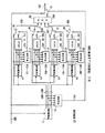
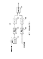
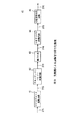
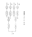
図1において、10は全体として本発明の実施例による変換回路を示し、従来について上述した図14の画像信号符号化装置1の変換回路2に適用することで本発明による画像信号伝送方法及び画像信号伝送装置を実現する。図1において入力画像信号S25は、図15について上述したウエーブレツト変換回路によつて実現される1段階のウエーブレツト(W)変換回路11に入力され、4つの帯域に分割されて係数S26〜S29になる。この係数S26〜S29と入力画像信号S25とは、判定回路12に入力される。判定回路12はウエーブレツト変換回路11でのウエーブレツト変換が有効な変換であつたか否か判断し制御信号S30を出力する。
【0014】
ウエーブレツト変換回路11から出力される係数S26は、ウエーブレツト変換回路11と同じウエーブレツト(W)変換回路13に入力され、4つの帯域に分割されて係数S31〜S34になる。またこの係数S31〜S34と係数S26が判定回路17に入力される。判定回路17ではウエーブレツト変換回路13での変換が有効な変換であつたか否かを判断し、制御信号S35を出力する。係数S31〜S34は多重化回路(MUX)21に入力され、多重化されて係数S51となる。係数S26と係数S51はウエーブレツト変換回路13での変換が有効な変換であつたか否かの制御信号S35の値に応じて、選択回路25で選択されて係数S55となる。
【0015】
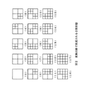
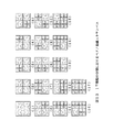
係数S27、S28、S29についても、それぞれウエーブレツト(W)変換回路14、15、16、判定回路18、19、20、多重化回路(MUX)22、23、24、選択回路26、27、28で同様の操作が行なわれる。この結果得られた係数S55〜S58は多重化回路(MUX)29で多重化されて係数S59となる。係数S25と係数S59は制御信号S30の値に応じて、選択回路30で選択されて係数S60となり、変換回路10の出力として送出される。この変換回路10によつて実現できる17種類の分割形態を、図2に列挙して示す。この変換回路10ではウエーブレツト変換を2段階までとしたが、変換回路を3段階以上に増やしていくことも容易に可能であり、この場合分割形態の種類もさらに多くなる。
【0016】
変換回路10の判定回路12(17〜20)の構成を図3に示す。変換回路10のウエーブレツト変換の基底としてHaar基底などの正規直交変換を選んだときに有効な手段として、変換の前後の係数の絶対値和を比較することで分割又は非分割の判定を行なつている。この判定回路12(17〜20)では変換後の係数S26〜S29(S31〜S34、S36〜S39、S41〜S44、S46〜S49)と変換前の係数S25(S26、S27、S28、S29)とを比較することにより変換の有効性を評価する。
【0017】
実際上判定回路12において、変換後の係数S26〜S29は多重化回路(MUX)31に入力され、多重化されて係数S61となる。この係数S61は逐次絶対値和計算回路32に入力される。絶対値和計算回路32は係数S61の絶対値和を計算し、係数S62として出力する。一方変換前の係数S25は逐次絶対値和計算回路33に入力される。絶対置和計算回路33は係数S25の絶対値和を計算し、係数S63として出力する。係数S62とS63は比較回路34に入力される。比較回路34ではどちらが小さいかを判定し、その結果を「0」又は「1」の制御信号でなる係数S64として出力する。
【0018】
この実施例の内容を4×4画素の画像に対するHaar基底によるウエーブレツト変換を例として説明する。4×4画素の画像に対するHaar基底ウエーブレツト変換の変換基底は、図4の示すようになる。ウエーブレツト変換の基底構成の形は、この1種類しかない。それに対して入力画像信号の各帯域の再分割を再帰的に行なういわゆるウエーブレツトパケツト変換と呼ばれる変換では、帯域2〜4に対して、さらに分割を進めたり帯域1の分割を行なわなかつたりする変換の中から、効果的な変換を選ぶということを行なう。
【0019】
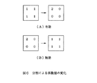
例えば帯域2に対して、さらに分割を進めるということは、図5(A)の形の基底で表されていた画像を、図5(B)の形の基底で表すということに他ならない。このような分割は、例えば帯域2の中に同じような値の係数が一様に分布している場合には有効な分割である。なぜならこのような場合には、変換後の形の基底の方が特定の基底、この場合には左上の基底に電力を集中できるからである。例として、帯域2の中の係数分布が図6(A)の左側であつた場合と図6(B)の左側であつた場合を考える。正規化されたHaar基底による変換によつて、それぞれその右側のように変換される。
【0020】
ここで図3について上述した判定回路12によれば、図6(A)の変換は有効となり、図6(B)の変換は無効になる。これは正規直交のウエーブレツトパケツト変換の前後でエネルギーは保存されていることを利用した方法である。変換の前後でエネルギーは保存されているにもかかわらず、変換後の係数の絶対値和が小さくなるということは特定の基底への電力集中が進んでいるということであり、変換後の係数の絶対値和が大きくなるということは特定の基底への電力集中が失われているということから、このような判断を行なつている。
【0021】
なお判定回路12は図3について上述した回路構成のほかにも、図3との対応部分に同一符号を付した図7に示すように、閾値上下判定回路35A、35B及びカウント回路36A、36Bによつて、分割の前後で閾値以下の絶対値を持つ係数の数を比べるものや、図3との対応部分に同一符号を付した図8に示すように、エントロピー計算回路37A、37Bによつて、分割の前後で係数のエントロピーを比べるものを用いることもできる。
【0022】
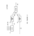
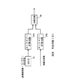
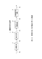
ここで図9に、画像信号をブロツク分解してブロツク毎にウエーブレツトパケツトの分割を切り替える画像信号符号化装置40を示す。この画像信号符号化装置40においては、入力画像信号S71はマクロブロツク変換回路41に入力され、マクロブロツク順に並び換えられて係数S72となる。係数S72は図1の変換回路10によつて実現されるウエーブレツトパケツト変換回路42に入力され、ブロツク毎にウエーブレツトパケツト変換されて係数S73となる。係数S73は量子化器43で量子化されて係数S74となる。
【0023】
係数S74はスキヤンパス変換回路44に入力され、スキヤンパス順に並び換えられて係数S75となる。係数S75は可変長符号化回路45に入力され、例えばハフマン符号化と零のランレングス符号化を組み合わせた可変長符号化を適用され係数S76となり、この係数S76が画像信号符号化装置40の出力として送出される。この場合分割をブロツク毎に切り替えることで基底の最適化をさらに高め、より効率の良い符号化が可能となる。
【0024】
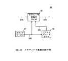
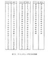
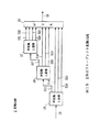
スキヤンパス変換回路44を図10に示す。このスキヤンパス変換回路44では、8×8の画像ブロツクに対するスキヤンパスとして、ペアノ曲線を用いるようになされている。実際上8×8画像ブロツクの量子化された64画素は、ブロツクの左上から1ライン毎にスキヤンパス変換回路44に係数S74として入力される。係数S74はカウンタ47の発生する出力S80を書き込みアドレスとして、一旦スキヤンパス変換用RAM46に蓄えられ、アドレスデコーダROM48の発生させた読み出しアドレスS81に従つて順次係数S75として出力される。ここでアドレスデコーダROM48のメモリマツプを図11に示す。
【0025】
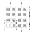
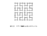
またペアノ曲線によるスキヤンパスの効果を、8×8の画像を例として説明する。8×8の離散点に対するペアノ曲線は図12に示すようになる。8×8の画像に対して、図1に上述した変換回路10によつて2段階までのウエーブレツトパケツト変換を行なう場合を考える。変換回路10によつて実現できる分割方法は図2に上述した17種類であるが、図12に示したペアノ曲線は、図13に示すようにこの17種類の全てに対してパスが帯域内で完結していることが分かる。
【0026】
パスが帯域を跨らないので、この1つのパスだけでどのような分割に対してもある程度は効率良く符号化が出来る。この性質は8×8画素のブロツクに対する3段階までのウエーブレツトパケツト変換に限ることではなく、あらゆる正方ブロツクの何段階のウエーブレツトパケツト変換に対しても成り立つ性質である。またスキヤンパスによる符号化をさらに高めたいときには、分割毎にスキヤンを切り替えるという方法も可能である。この方法ではハード構成は多少大きくなるが、各分割に対して最も効率的なスキヤンパスを適用できるので、ペアノ曲線によるスキヤンパスのみの場合よりも効率的な符号化が可能になる。
【0027】
以上の構成によれば、画像信号をウエーブレツト変換によつて複数帯域の成分に分割し、量子化して伝送する際に、入力画像の変換後の各帯域の係数の値の分布状況に応じて、効果的と思われるときには各帯域の再分割を再帰的に行なうようにしたことにより、入力画像内の画素値の分布状況に応じて、その分布状況に適した変換基底を構成して、どのような原画像に対しても効果的な変換を行なうことができる。
【0028】
なお上述の実施例においては、画像ブロツクとして4×4画素あるいは8×8画素の画像を取り上げて説明したが、画像のサイズはこれに限定されているわけではなく、例えば16×16画素の画像ブロツクに分解して変換することも可能であるし、720×496画素の画像全体を変換することも可能である。
【0029】
また上述の実施例においては、分割の制御を2次元ウエーブレツト変換を1つの単位として行なつているが、水平方向のみあるいは垂直方向のみを再帰的に分割するようにしても上述の実施例と同様の効果を実現できる。
【0030】
【発明の効果】
上述のように本発明によれば、画像信号をウエーブレツト変換によつて複数帯域の成分に分割し、量子化して伝送する際に、各帯域での変換後のウエーブレツト係数の絶対値和が、変換前のウエーブレツト係数の絶対値和よりも小さい場合に、当該帯域を再帰的に再分割することにより、入力画像内の画素値の分布状況に応じて、その分布状況に適した変換基底を構成し得る。これによりどのような原画像に対しても、効果的な変換を行なうことができ、また量子化を行なつた後も目立つた劣化は起こり難くなる。かくして画像の特性によらず伝送の際に画質の劣化を未然に防止し得る画像信号伝送方法及び画像信号伝送装置を実現できる。
また本発明によれば、画像信号をウエーブレツト変換によつて複数帯域の成分に分割し、量子化して伝送する画像信号伝送方法において、各帯域内で、絶対値が所定の閾値以下であるような係数の数が、変換前より変換後に多い場合、当該帯域を再帰的に再分割するることにより、入力画像内の画素値の分布状況に応じて、その分布状況に適した変換基底を構成し得る。これによりどのような原画像に対しても、効果的な変換を行なうことができ、また量子化を行なつた後も目立つた劣化は起こり難くなる。かくして画像の特性によらず伝送の際に画質の劣化を未然に防止し得る画像信号伝送方法及び画像信号伝送装置を実現できる。
【図面の簡単な説明】
【図1】本発明による画像信号伝送方法及び画像信号伝送装置の一実施例の変換回路の構成を示すブロツク図である。
【図2】図1の変換回路によつて実現できる17種類の分割形態の説明に供する略線図である。
【図3】図1の変換回路内の判定回路の構成を示すブロツク図である。
【図4】4×4画素についてのHaar基底によるウエーブレツト変換の基底の説明に供する略線図である。
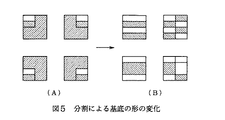
【図5】分割による基底の形の変化の説明に供する略線図である。
【図6】分割による係数値の変化の説明に供する略線図である。
【図7】図1の変換回路内の判定回路の他の構成を示すブロツク図である。
【図8】図1の変換回路内の判定回路のさらに他の構成を示すブロツク図である。
【図9】ブロツクに分解してからウエーブレツトパケツト変換を行なう画像信号符号化装置の構成を示すブロツク図である。
【図10】図9の画像信号符号化装置のスキヤンパス変換回路の構成を示すブロツク図である。
【図11】スキヤンパス変換回路内のスキヤンパス変換用アドレスデコーダROMの内容を示す図表である。
【図12】ペアノ曲線によるスキヤンパスの説明に供する略線図である。
【図13】17種類の分割形態に対応するペアノ曲線スキヤンパスを示す略線図である。
【図14】変換を用いる画像信号符号化装置の構成を示すブロツク図である。
【図15】変換回路として2次元ウエーブレツト変換回路の構成を示すブロツク図である。
【図16】2次元ウエーブレツト変換の1段階分のウエーブレツト変換回路の構成を示すブロツク図である。
【符号の説明】
1、40……画像信号符号化装置、2、10……変換回路、3、43……量子化器、4、44……スキヤンパス変換回路、5、45……可変長符号化回路、11、13〜16……ウエーブレツト(W)変換回路、12、17〜20……判定回路、21〜24、29、31……多重化回路(MUX)、25〜28、30……選択回路、32、33……絶対値計算回路、34……比較回路、35A、35B……閾値上下判定回路、36A、36B……カウント回路、37A、37B……エントロピー計算回路、41……マクロブロツク変換回路、42……ウエーブレツトパケツト変換回路、46……スキヤンパス変換用RAM、47……カウンタ、48……アドレスデコーダ。[0001]
【table of contents】
The present invention will be described in the following order.
Industrial application Conventional technology (FIGS. 14 to 16)
Means for Solving the Problems to be Solved by the Invention (FIG. 1)
Action (Figure 1)
Example (FIGS. 1 to 13)
BACKGROUND OF THE INVENTION
[Industrial applications]
The present invention relates to an image signal transmission method and an image signal transmission apparatus, and is applied to, for example, a method for remotely transmitting an image signal using a transmission medium having a limited transmission capacity, and recording and reproduction on a tape recorder / disc recorder or the like. It is suitable.
[0003]
[Prior art]
Conventionally, in a so-called image signal transmission system for transmitting an image signal to a remote place, such as a video conference system, or in an apparatus for digitizing an image signal and recording and reproducing the same on a video tape recorder or a video disk recorder, a transmission path or the like is used. In order to use the recording medium efficiently, it is necessary to reduce the amount of transmission information and recording information and to increase the transmission efficiency and recording efficiency by efficiently encoding significant information using the correlation of the digitized image signal. It has been made. As an encoding method using correlation, a transform encoding method is generally used in which an original signal is transformed using a discrete cosine transform (DCT), a wavelet transform, or the like, and then quantized and transmitted.
[0004]
FIG. 14 shows an image
[0005]
In this image signal encoding method, quantization is generally performed such that low-order coefficients are fine and high-order coefficients are coarsely quantized in consideration of human visual characteristics to reduce the amount of transmission information. As an example of the conversion circuit, FIG. 15 shows a configuration of a two-dimensional wavelet conversion circuit formed by three stages of wavelet conversion. Further, one stage of the two-dimensional wavelet conversion circuit is realized by the wavelet conversion circuit of FIG. In the wavelet conversion circuit of FIG. 16, an input signal S6 is filtered by a horizontal low-pass filter (LPF) and a horizontal high-pass filter (HPF), and then sub-sampled into coefficients S7 and S8. . The coefficients S7 and S8 are filtered by a low-pass filter in the vertical direction and a high-pass filter in the vertical direction and then sub-sampled to obtain coefficients S9 to S12. These coefficients S9 to S12 are sent out as outputs of the wavelet transform circuit. Is done. In this way, the input signal S6 is divided into coefficients S9 to S12 of four bands by one-stage conversion.
[0006]
The two-dimensional
[0007]
[Problems to be solved by the invention]
However, in transform coding such as DCT or wavelet transform, an image not suitable for the shape of the basis of the transform method, for example, an image having a sharp edge for DCT, or a smooth image for wavelet transform using Haar basis. When converting, there is a problem that the power cannot be concentrated even after the conversion, the coefficients are uniformly distributed, and if the quantization is performed, the image quality is remarkably deteriorated.
[0008]
The present invention has been made in consideration of the above points, and provides an image signal transmission method and an image signal transmission method capable of preventing deterioration of image quality regardless of image characteristics when image signals are wavelet-transformed and quantized and transmitted. An image signal transmission device is proposed.
[0009]
[Means for Solving the Problems]
In order to solve this problem, according to the present invention, in an image signal transmission method in which an image signal (S25) is divided into components of a plurality of bands by a wavelet transform, quantized and transmitted, the converted wave in each band is used. When the absolute value sum of the let coefficients is smaller than the absolute value sum of the wavelet coefficients before the conversion, the band is recursively redivided.
Further, in the present invention, in an image signal transmitting apparatus which divides an image signal (S25) into components of a plurality of bands by wavelet transform, quantizes and transmits the components, the coefficient value of each band after the conversion of the input image signal is obtained. Subdivision determining means (12 (17, 18, 19, 20)) for determining whether or not there is an effect of subdivision according to the distribution situation, and the subdivision determining means (12 (17, 18, 19, 20)) (11 (13, 14, 15, 16)) for recursively re-dividing each band according to the judgment result of (1), and the re-dividing judgment means (12 (17, 18, 19, 20)). Compares the sum of absolute values of the wavelet coefficients before and after conversion in each band, and recursively redivides the band if the sum of absolute values after conversion is small.
[0010]
Further, according to the present invention, in an image signal transmission method of dividing an image signal (S25) into components of a plurality of bands by wavelet transform, quantizing the image signal, and transmitting the quantized signal, the absolute value of each image signal is not more than a predetermined threshold value in each band. When the number of such coefficients is larger after conversion than before conversion, the band is recursively re-divided.
Further, in the present invention, in an image signal transmitting apparatus which divides an image signal (S25) into components of a plurality of bands by wavelet transform, quantizes and transmits the components, the coefficient value of each band after the conversion of the input image signal is obtained. Subdivision determining means (12 (17, 18, 19, 20)) for determining whether or not there is an effect of subdivision according to the distribution situation, and the subdivision determining means (12 (17, 18, 19, 20)) (11 (13, 14, 15, 16)) for recursively re-dividing each band according to the judgment result of (1), and the re-dividing judgment means (12 (17, 18, 19, 20)). In each band, when the number of coefficients whose absolute value is equal to or smaller than a predetermined threshold value is larger after conversion than before conversion, the band is determined to be recursively re-divided.
[0011]
[Action]
When the image signal (S25) is divided into components of a plurality of bands by the wavelet transform, and quantized and transmitted, the sum of the absolute values of the converted wavelet coefficients in each band is equal to the wavelet coefficient before the conversion. If the absolute value is smaller than the sum of the absolute values, the band can be recursively re-divided, so that a conversion base suitable for the distribution state can be formed according to the distribution state of the pixel values in the input image. This makes it possible to perform effective conversion on any original image, and makes it difficult for noticeable deterioration to occur even after quantization has been performed.
Further, in an image signal transmission method in which the image signal (S25) is divided into a plurality of bands by a wavelet transform, and quantized and transmitted, a coefficient whose absolute value is equal to or smaller than a predetermined threshold value in each band. Is larger after conversion than before conversion, by recursively subdividing the band, a conversion base suitable for the distribution state can be formed according to the distribution state of pixel values in the input image. . This makes it possible to perform effective conversion on any original image, and makes it difficult for noticeable deterioration to occur even after quantization has been performed.
[0012]
【Example】
An embodiment of the present invention will be described below in detail with reference to the drawings.
[0013]
In FIG. 1,
[0014]
The coefficient S26 output from the
[0015]
For the coefficients S27, S28 and S29, the wavelet (W)
[0016]
FIG. 3 shows the configuration of the determination circuit 12 (17 to 20) of the
[0017]
In practice, in the
[0018]
The contents of this embodiment will be described by taking as an example a wavelet transform based on a Haar basis for an image of 4 × 4 pixels. The transformation basis of the Haar basis wavelet transformation for the image of 4 × 4 pixels is as shown in FIG. There is only one type of basis configuration for the wavelet transform. On the other hand, in a conversion called repetitive so-called wavelet packet conversion in which re-division of each band of the input image signal is performed recursively, the
[0019]
For example, further division of
[0020]
Here, according to the
[0021]
In addition to the circuit configuration described above with reference to FIG. 3, the
[0022]
Here, FIG. 9 shows an image
[0023]
The coefficient S74 is input to the scan
[0024]
FIG. 10 shows the scan
[0025]
The effect of the scan pass by the Peano curve will be described using an 8 × 8 image as an example. A Peano curve for 8 × 8 discrete points is as shown in FIG. It is assumed that the wavelet packet conversion of up to two stages is performed on the 8.times.8 image by the
[0026]
Since the path does not extend over the band, coding can be performed to some extent efficiently with any one of the divisions using only this one path. This property is not limited to the wavelet packet conversion of up to three stages for the block of 8.times.8 pixels, but is also true for any number of stages of the wavelet packet conversion of any square block. If it is desired to further enhance the coding by the scan path, a method of switching the scan for each division is also possible. Although the hardware configuration is slightly larger in this method, the most efficient scan path can be applied to each division, so that more efficient encoding can be performed than when only the scan path using the Peano curve is used.
[0027]
According to the above configuration, when an image signal is divided into components of a plurality of bands by the wavelet transform, and quantized and transmitted, according to the distribution state of the coefficient values of each band after the conversion of the input image. When it seems to be effective, by performing re-division of each band recursively, according to the distribution state of the pixel values in the input image, a conversion base suitable for the distribution state is formed. Effective conversion can be performed on such an original image.
[0028]
In the above-described embodiment, an image of 4 × 4 pixels or 8 × 8 pixels has been described as an image block. However, the size of the image is not limited to this. For example, an image of 16 × 16 pixels is used. It is also possible to convert the image by decomposing it into blocks, or to convert the entire image of 720 × 496 pixels.
[0029]
In the above-described embodiment, the division control is performed using two-dimensional wavelet transform as one unit. However, the division may be recursively divided only in the horizontal direction or only in the vertical direction. Similar effects can be achieved.
[0030]
【The invention's effect】
As described above, according to the present invention, when an image signal is divided into components of a plurality of bands by a wavelet transform, and quantized and transmitted, the sum of absolute values of the converted wavelet coefficients in each band is calculated. If the absolute value of the wavelet coefficient before conversion is smaller than the sum of the absolute values, the band is recursively re-divided to obtain a transform base suitable for the distribution state of the pixel value in the input image. Can be configured. This makes it possible to perform effective conversion on any original image, and makes it difficult for noticeable deterioration to occur even after quantization has been performed. Thus, it is possible to realize an image signal transmission method and an image signal transmission apparatus capable of preventing deterioration of image quality during transmission regardless of image characteristics.
Further, according to the present invention, in an image signal transmission method for dividing an image signal into components of a plurality of bands by a wavelet transform, quantizing the image signal, and transmitting the quantized image signal, the absolute value is not more than a predetermined threshold value in each band. If the number of coefficients is larger after conversion than before conversion, the band is recursively re-divided to form a conversion base suitable for the distribution state according to the distribution state of pixel values in the input image. I can do it. This makes it possible to perform effective conversion on any original image, and makes it difficult for noticeable deterioration to occur even after quantization has been performed. Thus, it is possible to realize an image signal transmission method and an image signal transmission apparatus capable of preventing deterioration of image quality during transmission regardless of image characteristics.
[Brief description of the drawings]
FIG. 1 is a block diagram showing a configuration of a conversion circuit of an embodiment of an image signal transmission method and an image signal transmission device according to the present invention.
FIG. 2 is a schematic diagram for explaining 17 types of division forms that can be realized by the conversion circuit of FIG. 1;
FIG. 3 is a block diagram showing a configuration of a determination circuit in the conversion circuit of FIG.
FIG. 4 is a schematic diagram for explaining a basis of a wavelet transformation based on a Haar basis for 4 × 4 pixels;
FIG. 5 is a schematic diagram for explaining a change in shape of a base due to division;
FIG. 6 is a schematic diagram for explaining changes in coefficient values due to division;
FIG. 7 is a block diagram showing another configuration of the determination circuit in the conversion circuit of FIG. 1;
FIG. 8 is a block diagram showing still another configuration of the determination circuit in the conversion circuit of FIG. 1;
FIG. 9 is a block diagram showing a configuration of an image signal encoding apparatus that performs wavelet packet transformation after decomposing the image into blocks.
FIG. 10 is a block diagram showing a configuration of a scan path conversion circuit of the image signal encoding device of FIG. 9;
FIG. 11 is a table showing contents of a scan path conversion address decoder ROM in the scan path conversion circuit;
FIG. 12 is a schematic diagram illustrating a scan path using a Peano curve.
FIG. 13 is a schematic diagram showing Peano curve scan paths corresponding to 17 types of division modes.
FIG. 14 is a block diagram showing a configuration of an image signal encoding device using conversion.
FIG. 15 is a block diagram showing a configuration of a two-dimensional wavelet conversion circuit as a conversion circuit.
FIG. 16 is a block diagram showing a configuration of a wavelet conversion circuit for one stage of two-dimensional wavelet conversion.
[Explanation of symbols]
1, 40 image signal coding device, 2, 10, conversion circuit, 3, 43 quantizer, 4, 44 scan path conversion circuit, 5, 45 variable length coding circuit, 11, 13-16: Wavelet (W) conversion circuit, 12, 17-20: Judgment circuit, 21-24, 29, 31 ... Mux circuit (MUX), 25-28, 30 ... Selection circuit, 32 .., 33... Absolute value calculation circuit, 34... Comparison circuit, 35A, 35B... Threshold value upper / lower determination circuit, 36A, 36B ... count circuit, 37A, 37B ... entropy calculation circuit, 41 ... macroblock conversion circuit 42 a wavelet packet conversion circuit, 46 a scan path conversion RAM, 47 a counter, 48 an address decoder.
Claims (4)
上記各帯域での変換後のウエーブレツト係数の絶対値和が、変換前のウエーブレツト係数の絶対値和よりも小さい場合に、当該帯域を再帰的に再分割するようにした
ことを特徴とする画像信号伝送方法。 In an image signal transmission method for dividing an image signal into components of a plurality of bands by a wavelet transform, quantizing and transmitting the divided signals,
When the sum of absolute values of the wavelet coefficients after conversion in each band is smaller than the sum of absolute values of the wavelet coefficients before conversion, the band is recursively redivided.
An image signal transmission method characterized by the above-mentioned.
上記各帯域内で、絶対値が所定の閾値以下であるような係数の数が、変換前より変換後に多い場合、当該帯域を再帰的に再分割するようにしたIn each of the bands, when the number of coefficients whose absolute value is equal to or smaller than a predetermined threshold is larger after conversion than before conversion, the band is recursively redivided.
ことを特徴とする画像信号伝送方法。An image signal transmission method characterized by the above-mentioned.
入力画像信号の変換後の上記各帯域の係数値の分布状況に応じて、再分割の効果の有無を判断する再分割判定手段と、Depending on the distribution of the coefficient values of the respective bands after the conversion of the input image signal, re-division determining means for determining whether or not there is an effect of sub-division,
当該再分割判定手段の判断結果に応じて各帯域を再帰的に再分割する再分割手段とRe-dividing means for re-dividing each band recursively according to the judgment result of the sub-dividing judgment means;
を具え、With
上記再分割判定手段は、上記各帯域において、変換前と変換後におけるウエーブレツト係数の絶対値和を比較して、変換後の絶対値和が小さい場合に、当該帯域を再帰的に再分割するようにしたThe subdivision determining means compares the sum of absolute values of the wavelet coefficients before and after the conversion in each band, and recursively redivides the band if the sum of the absolute values after the conversion is small. Did
ことを特徴とする画像信号伝送装置。An image signal transmission device, characterized in that:
入力画像信号の変換後の上記各帯域の係数値の分布状況に応じて、再分割の効果の有無を判断する再分割判定手段と、Depending on the distribution of the coefficient values of the respective bands after the conversion of the input image signal, re-division determining means for determining whether or not there is an effect of sub-division,
当該再分割判定手段の判断結果に応じて各帯域を再帰的に再分割する再分割手段とRe-dividing means for re-dividing each band recursively according to the judgment result of the sub-dividing judgment means;
を具え、With
上記再分割判定手段は、上記各帯域において、絶対値が所定の閾値以下であるような係数の数が、変換前より変換後に多い場合、当該帯域を再帰的に再分割するように判断するIf the number of coefficients whose absolute value is equal to or smaller than a predetermined threshold value is larger after conversion than before conversion in each of the bands, the subdivision determination unit determines to redivide the band recursively.
ことを特徴とする画像信号伝送装置。An image signal transmission device, characterized in that:
Priority Applications (1)
| Application Number | Priority Date | Filing Date | Title |
|---|---|---|---|
| JP27011294A JP3591663B2 (en) | 1994-08-31 | 1994-08-31 | Image signal transmission method and image signal transmission device |
Applications Claiming Priority (1)
| Application Number | Priority Date | Filing Date | Title |
|---|---|---|---|
| JP27011294A JP3591663B2 (en) | 1994-08-31 | 1994-08-31 | Image signal transmission method and image signal transmission device |
Publications (2)
| Publication Number | Publication Date |
|---|---|
| JPH0879755A JPH0879755A (en) | 1996-03-22 |
| JP3591663B2 true JP3591663B2 (en) | 2004-11-24 |
Family
ID=17481713
Family Applications (1)
| Application Number | Title | Priority Date | Filing Date |
|---|---|---|---|
| JP27011294A Expired - Fee Related JP3591663B2 (en) | 1994-08-31 | 1994-08-31 | Image signal transmission method and image signal transmission device |
Country Status (1)
| Country | Link |
|---|---|
| JP (1) | JP3591663B2 (en) |
-
1994
- 1994-08-31 JP JP27011294A patent/JP3591663B2/en not_active Expired - Fee Related
Also Published As
| Publication number | Publication date |
|---|---|
| JPH0879755A (en) | 1996-03-22 |
Similar Documents
| Publication | Publication Date | Title |
|---|---|---|
| JP3337583B2 (en) | Variable length encoder | |
| EP0580454B1 (en) | Coding and decoding of digital data | |
| JP3085024B2 (en) | Image recompressor and image recording device | |
| JPH05236447A (en) | Compressed video data generation method | |
| JP2008005504A (en) | Flag encoding method, flag decoding method, and apparatus using the method | |
| JP3016456B2 (en) | Adaptive variable length coding method | |
| JPH05137114A (en) | Digital video tape recorder | |
| JP3591663B2 (en) | Image signal transmission method and image signal transmission device | |
| JP2963958B2 (en) | High efficiency coding device | |
| JP3166501B2 (en) | Image recompression method and image recompression device | |
| KR100361804B1 (en) | Apparatus and method for compressing and depressing movable images using Wavelet theory | |
| JP3559314B2 (en) | Image compression device | |
| JPH02122767A (en) | Encoding/decoding system for picture signal | |
| JPH0787496A (en) | Image signal transmission method and image signal transmission device | |
| JPH06113140A (en) | Image processing device | |
| KR0134324B1 (en) | Variable length method of data compression | |
| JP2597003B2 (en) | Image signal compression coding device | |
| JPH0366228A (en) | Block encoder and decoder | |
| JP2710135B2 (en) | Adaptive coding between frames / intra-frame | |
| Nasiopoulos et al. | A high-quality fixed-length compression scheme for color images | |
| JPH09224246A (en) | Image compression encoding and image compression decoding device | |
| JPH1188183A (en) | Wavelet converter, its method, wavelet inverse converter, its method, image coder, its method, image decoder and its method | |
| JP2620163B2 (en) | High efficiency coding device | |
| KR0166720B1 (en) | Variable length encoder | |
| JP2700355B2 (en) | Image data compression device |
Legal Events
| Date | Code | Title | Description |
|---|---|---|---|
| A977 | Report on retrieval |
Free format text: JAPANESE INTERMEDIATE CODE: A971007 Effective date: 20031209 |
|
| A131 | Notification of reasons for refusal |
Free format text: JAPANESE INTERMEDIATE CODE: A131 Effective date: 20031219 |
|
| A521 | Written amendment |
Free format text: JAPANESE INTERMEDIATE CODE: A523 Effective date: 20040217 |
|
| TRDD | Decision of grant or rejection written | ||
| A01 | Written decision to grant a patent or to grant a registration (utility model) |
Free format text: JAPANESE INTERMEDIATE CODE: A01 Effective date: 20040806 |
|
| A61 | First payment of annual fees (during grant procedure) |
Free format text: JAPANESE INTERMEDIATE CODE: A61 Effective date: 20040819 |
|
| FPAY | Renewal fee payment (event date is renewal date of database) |
Free format text: PAYMENT UNTIL: 20080903 Year of fee payment: 4 |
|
| FPAY | Renewal fee payment (event date is renewal date of database) |
Free format text: PAYMENT UNTIL: 20080903 Year of fee payment: 4 |
|
| FPAY | Renewal fee payment (event date is renewal date of database) |
Free format text: PAYMENT UNTIL: 20090903 Year of fee payment: 5 |
|
| LAPS | Cancellation because of no payment of annual fees |