JP3586773B2 - Bed fall warning device - Google Patents
Bed fall warning device Download PDFInfo
- Publication number
- JP3586773B2 JP3586773B2 JP2001276777A JP2001276777A JP3586773B2 JP 3586773 B2 JP3586773 B2 JP 3586773B2 JP 2001276777 A JP2001276777 A JP 2001276777A JP 2001276777 A JP2001276777 A JP 2001276777A JP 3586773 B2 JP3586773 B2 JP 3586773B2
- Authority
- JP
- Japan
- Prior art keywords
- bed
- alarm device
- control box
- fall prediction
- patient
- Prior art date
- Legal status (The legal status is an assumption and is not a legal conclusion. Google has not performed a legal analysis and makes no representation as to the accuracy of the status listed.)
- Expired - Fee Related
Links
Images


Classifications
-
- A—HUMAN NECESSITIES
- A61—MEDICAL OR VETERINARY SCIENCE; HYGIENE
- A61B—DIAGNOSIS; SURGERY; IDENTIFICATION
- A61B5/00—Measuring for diagnostic purposes; Identification of persons
- A61B5/103—Detecting, measuring or recording devices for testing the shape, pattern, colour, size or movement of the body or parts thereof, for diagnostic purposes
- A61B5/11—Measuring movement of the entire body or parts thereof, e.g. head or hand tremor, mobility of a limb
- A61B5/1113—Local tracking of patients, e.g. in a hospital or private home
- A61B5/1115—Monitoring leaving of a patient support, e.g. a bed or a wheelchair
Landscapes
- Health & Medical Sciences (AREA)
- Life Sciences & Earth Sciences (AREA)
- Heart & Thoracic Surgery (AREA)
- Medical Informatics (AREA)
- Physics & Mathematics (AREA)
- Dentistry (AREA)
- Biophysics (AREA)
- Pathology (AREA)
- Engineering & Computer Science (AREA)
- Biomedical Technology (AREA)
- Physiology (AREA)
- Oral & Maxillofacial Surgery (AREA)
- Molecular Biology (AREA)
- Surgery (AREA)
- Animal Behavior & Ethology (AREA)
- General Health & Medical Sciences (AREA)
- Public Health (AREA)
- Veterinary Medicine (AREA)
- Invalid Beds And Related Equipment (AREA)
- Accommodation For Nursing Or Treatment Tables (AREA)
Description
【0001】
【発明の属する技術分野】
本発明は病院、福祉施設、在宅介護において衰弱した手術後の患者や高齢者のベッドからの転落事故を未然に防ぐために通報・警報するため、また全国的に患者の抑制廃止運動が展開されているが適切な集中管理設備がなく看護人による巡廻監視強化しかないのが現状であり、その対策用のベッド落下予知警報装置に関する技術。
【0002】
【従来の技術】
年々高齢化が進むなかで病院、福祉施設の看護人等の不足等もあり入院・入所患者のベッド落下事故の多発に加えて患者の抑制廃止運動が高まることは多くの病院、福祉施設がかかえる大きな問題点で病院内・福祉施設内等を細めに巡廻する以外に方法は見受けられないのが現状である。特に夜間勤務帯では少人数のためベッド落下事故を見落しやすく現実に事故が増加傾向にもある。そこで、ベッド落下事故防止法ではないが痴呆徘徊検知法として室内監視カメラ等の利用も見受けられたが、現在はプライバシー侵害等で使用禁止の風潮にある。その他の方法としてマット式センサや離床センサシート等が商品化されているが、これらの方法では患者がベッドから落ちた後の検知になることや、マットを避けて通過する場合もあり特に病院等では患者に接触する物であることから非衛生的商品と見られたり感染症防止対策の一つとして床等にも物(マット等)を置かない運動も展開されつつあり特にベッド落下事故を防ぐ手段には適用困難である。
また先願出願として特許・公告NO. H07−034793の「ベッドにおける徘徊検出手段」があるが、これは特殊ベッド用に作られた赤外線センサ方式で痴呆徘徊専用装置としたものである。
この装置は特殊ベッド柵の両端・上部に投光器と受光器を装備したもので、痴呆徘徊患者がセンサを取付けた柵の上部を乗り越える時に検知されるもので検知エリアが患者に接近しすぎるためベッド上での患者の寝返りや挙動に伴う身体・衣服・布団・シーツ・カーテン等による誤動作発生等も懸念され、まだ市場では見受けられない。現状ではベッド落下防止対策としては依然として看護人等による巡廻監視体制の強化などが求められている。
【0003】
【発明が解決しようとする課題】
しかし、看護人等の不足の中で常時巡廻監視することは困難であるので集中監視を行なう方法が検討されてきているが、まだ適切な設備、技術が開発されていない。そこで本発明が解決する為の課題として次の事項を解決する必要がある。
1.メーカ別、機種別の多種多様なベッドに適用出来るようにする。
2.数多くの患者の行動・状況にも対応出来るようにする。
3.ベッドにセンサ装置が簡単に取付け取外しが出来るようにする。
4.センサ部等が軽量・コンパクトで病室内等で目立たないような装置にする。
5.既設の押ボタンスイッチと共用出来るようにする。
6.既設のナースコール回線に出力出来るようにする。
7.感染症対策や安全衛生面からも装置は、患者や寝具、病室床面等と非接触式にする。
以上の課題を解決してベッド落下事故を未然に防ぐための装置を開発する。
【0004】
【課題を解決するための手段】
本発明に係るベッド落下予知警報装置は、患者又は高齢者がベッドから転落する事故を未然に防ぐために通報するベッド落下予知警報装置であって、ベッドフレームに、ベッドフレーム挟み取付治具部及び締付けボルトを介して取付けられる制御ボックスと、先端に光センサ拡散反射型が装着され、他端が前記制御ボックスの上部に配設された曲折可能なフレキシブルパイプと、前記制御ボックス内に配置され、前記フレキシブルパイプ内を通る前記光センサ拡散反射型の光センサケーブルが接続され、その出力がナースコール用の押しボタンスイッチに並列に接続される信号処理回路とを有し、前記フレキシブルパイプの他端が配設された前記制御ボックスと前記ベッドフレーム挟み取付治具部とは一体化構造となって、前記ベッドから降りようとする患者又は高齢者の身体や衣服を、前記光センサ拡散反射型の照射による反射光で検知して前記制御ボックス内の信号処理回路により、その接点信号を並列接続している前記押ボタンスイッチのナースコール回線に連結して出力する。
これにより患者がベッドから降りようとする初期段階で看護人がかけつけて制止したりサポートすることでベッド落下事故を未然に防ぐことができる。
【0005】
【発明の実施の形態】
添付した図面を参照しつつ本発明を具体化した実施の形態につき説明し本発明の理解に供する。ここに図1は本発明の一実施の形態に係るベッド落下予知警報装置の構成を示す。
図2は本発明のベッド落下予知警報装置の実施例を示す。
図3は本発明のベッド落下予知警報装置の制御回路ブロック図を示す。
図4は光センサ部本体と制御ボックス本体を分離構造とした本発明のベッド落下予知警報装置の構成を示す。
図5は本発明のベッド落下予知警報装置の実施例を示す。
図6はベッド落下予知警報装置の応用回路方式として出力信号をAC電源ラインを通じて他の部屋で信号入力できて警報・光表示装置に出力させる応用実施例を示す。この回路に使用する部品には、市販商品を組込み利用する。
図7はベッド落下予知警報装置の応用回路方式で、出力信号を無線伝送出力方式として他の部屋等でも無線受信できて警報連絡を受けることが出来る微弱電波利用での応用実施例を示す、この回路の無線部には市販商品を組込むものである。
【0006】
【実施例】
以上の各図について詳細を説明する。
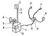
図1はベッド落下予知警報装置の構成図を示す。フレキシブルパイプ2の先端に、光センサ拡散反射型1を装着して前記フレキシブルパイプ2の他端を制御ボックス本体6上部に配設して同じく前記制御ボックス本体6上部にベッドフレーム挟み取付治具部4と締付けボルト5を配設している。
前記制御ボックス本体6には前面部に表示灯付き電源スイッチ7を設置している。また前記制御ボックス本体6内には信号処理回路8が組込まれている。前記光センサ拡散反射型1の光センサケーブル3は前記フレキシブルパイプ2の中を通って前記制御ボックス本体6の信号処理回路8内の入力信号回路31に接続している。
前記制御ボックス6からは制御ケーブル10が中継ボックス13を通じてACアダプター9の電源ケーブルと出力信号回路32と押ボタンスイッチ12に結線されている。
出力信号回路32は押しボタンスイッチ12と並列に接続され、ナースコールユニット14のナースコールコネクター付ケーブル11を通じて既設のナースセンターへ連結される。
図2は前記ベッド落下予知警報装置の実施例を示すもので、ベッド17のベッドフレーム18の下部に制御ボックス本体6をベッドフレーム取付け治具部4と締付けボルト5で取付け、前記フレキシブルパイプ2の先端に取付けている光センサ拡散反射型1の照射方向を患者が前記ベッド17を降りなれている位置に向けてベッド柵20より少し離した位置に誤動作を受けないで身体及び衣服を照射するようにフレキシブルパイプ2を曲折して位置・調整をして設定する。表示灯付き電源スイッチ7をONにした状態で患者がベッド17から降りようとするとき身体及び衣服が光センサ拡散反射型1の照射範囲に入った時に反射光による検知信号が信号処理回路8の入力信号回路31に入り、出力信号回路32を通じて接点信号がナースコールコネクター付ケーブル11よりナースコールコネクター15を通じてナースセンターに通報・警報が入るようになっている。その時点で看護人が患者の所へ出向き患者の動作を制止及びサポートすることにより、ベッドからの落下事故を未然に防止する事が出来る。
なお押ボタンスイッチ12も並列接続されて通常の押ボタンスイッチによるナースコールも出来る。
図3はベッド落下予知警報装置の電気回路を回路構成ブロック図として示している。光センサ拡散反射型1の検知信号は信号処理回路8を通じて押ボタンスイッチ12と中継ボックス13にて並列接続され、ナースコールコネクター付きケーブル11を通じてナースコールコネクター15より接点信号出力をナースセンターに出力させ通報・警報することが出来る。
図4に示すところのベッド落下予知警報装置についてはフレキシブルパイプ2の先端に光センサ拡散反射型1を装着して前記フレキシブルパイプ2の他端にベッドフレーム挟み取付治具22を配設した光センサ部本体36とは別にベッドフレーム挟み取付治具部4を上部に配設した制御ボックス本体6とニつへ分離構造化した事を特徴とするベッド落下予知警報装置を示す。
図5に示すところのベッド落下予知警報装置は実施例を示すもので、制御ボックス本体6をベッドフレーム18に取付けて光センサ部本体36をヘッドボード34あるいはフットボード35の上部に挟みつけて取付ける方法や、ベッドフレーム18下部に光センサ部本体36を挟みつけて取付ける方法で、隙間が狭い場所の取り付けが可能になったことから、患者の生活習慣・特性に会わせて光センサ部本体36の取付位置・方向を変えて、その患者の初期動作を検知できる最適位置に取り付けられることを特徴にしたベッド落下予知警報装置を示す。
図6は制御ボックス本体6の中の信号処理回路8にAC電源ライン信号送信回路23を配設して、AC電源コンセント25に差し込むことで検知信号がAC電源ライン内を伝わって他の室のAC電源コンセント26を通じてAC電源ライン信号入力警報装置28に入り警報を発することが出来る。
図7は前記制御ボックス本体6の信号処理回路8の出力信号回路32に無線送信回路29を配設して、検知信号は無線受信警報装置30に通報・警報される。以上本発明の実施の形態を説明したが本発明はこの実施の形態に限定されるものではなく、フレキシブルパイプを伸縮式アンテナパイプに変更したりして、本発明の要旨を脱しない条件の変更は全て本発明の適用範囲である。
また制御ボックス本体6のベッドフレーム挟み取付治具部4は前記に示すような取付治具のみに限定されるものではなく要旨を脱しない取付治具は本発明の適用範囲である。
【0007】
【発明の効果】
本発明により虚弱な手術後の患者や高齢者等がベッドから降りようとする時に患者の身体や衣服等をいち早く光センサ拡散反射型で検知してナースセンターへ通報・警報されるため看護人が患者のところへ出向き、ベッドから降りようとする動作を制止及びサポートしてベッド落下事故を未然に防止する事ができる。
本発明は事故を未然に防ぐための看護人をサポートをするための装置であり、押ボタンスイッチと光センサ拡散反射型のベッド落下予知警報装置の出力信号の並列接続方式により既存のナースコールシステムを改造することなく本発明を附加するだけで使用できるため安価なベッド落下予知警報システムになる。また近年は高齢化時代を迎えて病院・施設での抑制廃止の方向がきまり転落・転倒事故の増加にともない訴訟件数も増加してきている。
しかし限られた人数で巡廻監視強化にも限界があることから多くの病院施設でも困難な局面にたたされている。また感染症の問題を始め安全・衛生面からも患者や看護人をサポートするための道具としても本発明は十分活用できる。
以上の理由からベッド落下予知警報装置は多大な効果を生み出すことになる。
【図面の簡単な説明】
【図1】ベッド落下予知警報装置の説明図を示す。
【図2】ベッド落下予知警報装置の実施例を示す。
【図3】ベッド落下予知警報装置の回路ブロック図を示す。
【図4】ベッド落下予知警報装置の説明図を示す。
【図5】ベッド落下予知警報装置の実施例を示す。
【図6】AC電源ライン信号型・ベッド落下予知警報装置の実施例を示す。
【図7】無線信号型・ベッド落下予知警報装置の実施例を示す。
【符号の説明】
1:光センサ拡散反射型、2:フレキシブルパイプ、3:光センサケーブル、4:ベッドフレーム挟み取付治具部、5:締付けボルト、6:制御ボックス本体、7:表示灯付き電源スイッチ、8:信号処理回路、9:ACアダプター(AC/DC)、10:制御ケーブル、11:ナースコールコネクター付ケーブル、12:押ボタンスイッチ、13:中継ボックス、14:ナースコールユニット、15:ナースコールコネクター、16:電源コンセント、17:ベッド、18:ベッドフレーム、19:ベッド支柱、20:ベッド柵、21:フレキシブルパイプ固定部、22:ベッドフレーム挟み取付治具、23:AC電源ライン信号送信回路、24:AC電源ライン出力信号用電源コード、25:AC電源コンセント、26:AC電源コンセント、27:AC電源ライン入力信号用電源コード、28:AC電源ライン信号入力警報装置、29:無線送信回路、30:無線受信警報装置、31:入力信号回路、32:出力信号回路、34:ヘッドボード、35:フットボード、36:光センサ部本体[0001]
TECHNICAL FIELD OF THE INVENTION
The present invention has been developed to report and warn patients to prevent fallout from beds of patients and elderly people after surgery in hospitals, welfare facilities, and home care that have been debilitated, and to abolish patient suppression campaigns nationwide. there is a current situation is not only Megumegu monitoring strengthening by the nurse without proper centralized management equipment, base head fall prediction technology related to an alarm device for the measures.
[0002]
[Prior art]
As aging progresses year by year, there is a shortage of nurses at hospitals and welfare facilities, etc. At present, there is no other method except for patrols in hospitals and welfare facilities due to major problems. Especially in the night shift, it is easy to overlook bed falling accidents due to the small number of people, and there are actually increasing accidents. Therefore, although it is not a bed fall accident prevention method, use of an indoor surveillance camera or the like has been found as a method for detecting dementia wandering, but the use is currently banned due to privacy violation. As other methods, mat-type sensors and sensor sheets for getting out of bed have been commercialized, but in these methods, patients can be detected after falling off the bed, or they may pass by avoiding the mat, especially in hospitals etc. Is an unsanitary product because it is in contact with the patient, and as one of the measures to prevent infectious diseases, exercises that do not place objects (mats, etc.) on the floor etc. are also being developed, especially preventing falling beds accidents It is difficult to apply to the means.
Further, as a prior application, there is a “wandering detection means in bed” of Patent Publication No. H07-034793, which is a device dedicated to dementia wandering by an infrared sensor system made for a special bed.
This device is equipped with a transmitter and a receiver at both ends and upper part of the special bed fence, and is detected when a patient with dementia wanders over the fence on which the sensor is installed.The detection area is too close to the patient because the detection area is too close to the patient. There is also concern about the occurrence of malfunctions due to the body, clothes, futons, sheets, curtains, etc. associated with the patient turning over and behaviour, and is not yet found in the market. At present, there is still a need for measures to prevent beds from falling, such as strengthening the patrol monitoring system by nurses.
[0003]
[Problems to be solved by the invention]
However, it is difficult to constantly perform patrol monitoring due to the shortage of nurses and the like, and methods for centralized monitoring have been studied. However, appropriate facilities and technologies have not yet been developed. Therefore, the following items need to be solved as problems to be solved by the present invention.
1. It can be applied to a wide variety of beds by manufacturer and model.
2. Be able to respond to the behaviors and situations of many patients.
3. A sensor device is easily attached to and detached from the bed.
4. The sensor is designed to be lightweight and compact so that it is not noticeable in hospital rooms.
5. To be able to share with existing pushbutton switches.
6. Output to the existing nurse call line.
7. The device should be non-contact type with patients, bedding, hospital room floor, etc. from the viewpoint of infection control and health and safety.
To solve the above problems, we will develop a device to prevent bed fall accidents.
[0004]
[Means for Solving the Problems]
A bed fall prediction alarm device according to the present invention is a bed fall prediction alarm device for notifying a patient or an elderly person of falling down from a bed in order to prevent the accident, and the bed frame includes a bed frame sandwiching jig and a fastening device. A control box attached via bolts, an optical sensor diffuse reflection type mounted at the tip, a bendable flexible pipe disposed at the other end above the control box, and disposed in the control box; The optical sensor cable of the optical sensor diffuse reflection type passing through the flexible pipe is connected, and a signal processing circuit whose output is connected in parallel to a push button switch for a nurse call is provided. The arranged control box and the bed frame sandwiching jig have an integrated structure, and can be lowered from the bed. The push button that detects the body or clothing of the patient or elderly person to be detected by the light reflected by the light sensor diffuse reflection type illumination, and connects the contact signals in parallel by a signal processing circuit in the control box. Connect to the switch's nurse call line and output .
Thus, the bed drop accident can be prevented beforehand by the nurse to stop and support the patient at the initial stage when the patient tries to get out of the bed.
[0005]
BEST MODE FOR CARRYING OUT THE INVENTION
Embodiments embodying the present invention will be described with reference to the accompanying drawings to provide an understanding of the present invention. FIG. 1 shows a configuration of a bed fall prediction alarm device according to an embodiment of the present invention.
FIG. 2 shows an embodiment of the bed fall prediction alarm device of the present invention.
FIG. 3 shows a block diagram of a control circuit of the alarm device for predicting a bed drop according to the present invention.
FIG. 4 shows a configuration of the bed fall prediction alarm device of the present invention in which the optical sensor unit main body and the control box main body are separated.
FIG. 5 shows an embodiment of the bed fall prediction alarm device of the present invention.
FIG. 6 shows an application example of an application circuit system of the bed fall prediction alarm device, in which an output signal can be input in another room through an AC power supply line and output to an alarm / light display device. Commercially available products are incorporated and used as components used in this circuit.
FIG. 7 is an application circuit system of a bed fall prediction alarm device, which shows an application example using a weak radio wave which can receive an alarm signal and receive an alarm communication in another room as an output signal by a wireless transmission output method. Commercial products are incorporated in the radio section of the circuit.
[0006]
【Example】
Details of each of the above figures will be described.
FIG. 1 shows a configuration diagram of a bed fall prediction alarm device. The tip of the
The control box
From the
The
Figure 2 is mounted in the embodiment indicates a bed frame mounting
The
FIG. 3 shows an electric circuit of the bed fall prediction alarm device as a circuit configuration block diagram. The detection signal of the optical sensor diffuse
FIG optical sensor disposed mounting
Bed fall prediction alarm system where FIG. 5 shows an embodiment, the
FIG. 6 shows an arrangement in which an AC power supply line
In FIG. 7, a
The mounting jig bed frame scissors mounting
[0007]
【The invention's effect】
According to the present invention, when a patient or an elderly person after a fragile operation tries to get out of bed, the patient's body or clothes are detected as soon as possible by a light sensor diffuse reflection type and notified to a nurse center and an alarm is issued, so that a nurse is required. The movement to go to the patient and get out of the bed is stopped and supported, thereby preventing the bed falling accident.
The present invention is a device for supporting a nurse to prevent an accident before it occurs, and an existing nurse call system is provided by a parallel connection method of a push button switch and an output signal of an optical sensor diffuse reflection type bed fall prediction alarm device. Since the present invention can be used only by adding the present invention without remodeling, an inexpensive bed fall prediction alarm system can be provided. In recent years, the number of lawsuits has been increasing with the increase in falls and fall accidents due to the elimination of deterrence at hospitals and facilities in the age of aging.
However, many hospital facilities are facing difficult situations due to the limited number of people and the limited ability to enhance patrol surveillance. In addition, the present invention can be sufficiently used as a tool for supporting patients and nurses from the viewpoint of safety and hygiene including the problem of infectious diseases.
For the above reasons, the bed fall prediction alarm device produces a great effect.
[Brief description of the drawings]
FIG. 1 is an explanatory view of a bed fall prediction alarm device.
FIG. 2 shows an embodiment of a bed fall prediction alarm device.
FIG. 3 shows a circuit block diagram of a bed fall prediction alarm device.
FIG. 4 is an explanatory diagram of a bed fall prediction alarm device.
FIG. 5 shows an embodiment of a bed fall prediction alarm device.
FIG. 6 shows an embodiment of an AC power line signal type / bed fall prediction alarm device.
FIG. 7 shows an embodiment of a wireless signal type bed fall prediction alarm device.
[Explanation of symbols]
1: Light sensor diffuse reflective, 2: flexible pipe, 3: optical sensor cable, 4: bed frame scissors mounting jig unit, 5: tighten bolts, 6: control box body, 7: power switch-out with indicator , 8: signal processing circuit, 9: AC adapter (AC / DC), 10: control cable, 11: cable with nurse call connector, 12: push button switch, 13: relay box, 14: nurse call unit, 15: nurse call connector, 16: power outlet, 17: bed, 18: bed frame, 19: bed posts, 20: Bed rail, 21: flexible pipe fixing portion, 22: bed frame scissors mounting jig, 23: AC power line signal transmission Circuit, 24: AC power line output signal power cord, 25: AC power outlet, 26: AC power outlet G, 27: AC power line input signal power cord, 28: AC power line signal input alarm, 29: wireless transmission circuit, 30: wireless reception alarm, 31: input signal circuit, 32: output signal circuit, 34: headboard, 35: foot board, 36: optical sensor body
Claims (2)
ベッドフレームに、ベッドフレーム挟み取付治具部及び締付けボルトを介して取付けられる制御ボックスと、
先端に光センサ拡散反射型が装着され、他端が前記制御ボックスの上部に配設された曲折可能なフレキシブルパイプと、
前記制御ボックス内に配置され、前記フレキシブルパイプ内を通る前記光センサ拡散反射型の光センサケーブルが接続され、その出力がナースコール用の押しボタンスイッチに並列に接続される信号処理回路とを有し、
前記フレキシブルパイプの他端が配設された前記制御ボックスと前記ベッドフレーム挟み取付治具部とは一体化構造となって、
前記ベッドから降りようとする患者又は高齢者の身体や衣服を、前記光センサ拡散反射型の照射による反射光で検知して前記制御ボックス内の信号処理回路により、その接点信号を並列接続している前記押ボタンスイッチのナースコール回線に連結して出力することを特徴とするベッド落下予知警報装置。 A bed fall prediction alarm device that notifies a patient or an elderly person to prevent an accident of falling off the bed,
A control box attached to the bed frame via a bed frame sandwiching mounting jig and a fastening bolt;
A bendable flexible pipe with an optical sensor diffuse reflection type mounted at the tip and the other end disposed above the control box,
A signal processing circuit arranged in the control box, connected to the optical sensor diffuse reflection type optical sensor cable passing through the flexible pipe, and having an output connected in parallel to a nurse call push button switch. And
The control box in which the other end of the flexible pipe is disposed and the bed frame sandwiching mounting jig have an integrated structure,
The body or clothes of the patient or the elderly trying to get off the bed is detected by the light reflected by the diffuse reflection type light sensor, and the contact signals are connected in parallel by a signal processing circuit in the control box. A bed fall prediction alarm device, which outputs the signal by connecting to a nurse call line of the push button switch .
Priority Applications (1)
| Application Number | Priority Date | Filing Date | Title |
|---|---|---|---|
| JP2001276777A JP3586773B2 (en) | 2000-09-19 | 2001-09-12 | Bed fall warning device |
Applications Claiming Priority (3)
| Application Number | Priority Date | Filing Date | Title |
|---|---|---|---|
| JP2000283197 | 2000-09-19 | ||
| JP2000-283197 | 2000-09-19 | ||
| JP2001276777A JP3586773B2 (en) | 2000-09-19 | 2001-09-12 | Bed fall warning device |
Publications (3)
| Publication Number | Publication Date |
|---|---|
| JP2002165845A JP2002165845A (en) | 2002-06-11 |
| JP2002165845A5 JP2002165845A5 (en) | 2004-08-19 |
| JP3586773B2 true JP3586773B2 (en) | 2004-11-10 |
Family
ID=26600201
Family Applications (1)
| Application Number | Title | Priority Date | Filing Date |
|---|---|---|---|
| JP2001276777A Expired - Fee Related JP3586773B2 (en) | 2000-09-19 | 2001-09-12 | Bed fall warning device |
Country Status (1)
| Country | Link |
|---|---|
| JP (1) | JP3586773B2 (en) |
Families Citing this family (4)
| Publication number | Priority date | Publication date | Assignee | Title |
|---|---|---|---|---|
| AU2004210462A1 (en) * | 2003-02-06 | 2004-08-19 | Conseng Pty Ltd | A bed monitoring system |
| JP4607921B2 (en) * | 2007-06-28 | 2011-01-05 | 日本電信電話株式会社 | Pre-bed motion detection apparatus, pre-bed motion detection program, and pre-bed motion detection method |
| JP5167159B2 (en) * | 2009-01-29 | 2013-03-21 | 株式会社ケアコム | Nurse call system |
| KR101096242B1 (en) * | 2009-07-20 | 2011-12-22 | (주)더난 | The falled patient monitoring system using the pressure-pad |
-
2001
- 2001-09-12 JP JP2001276777A patent/JP3586773B2/en not_active Expired - Fee Related
Also Published As
| Publication number | Publication date |
|---|---|
| JP2002165845A (en) | 2002-06-11 |
Similar Documents
| Publication | Publication Date | Title |
|---|---|---|
| JPH0371131B2 (en) | ||
| US4947152A (en) | Patient monitoring system | |
| US9293026B2 (en) | Bed exit night light with increased functionality | |
| US8432287B2 (en) | Apparatus for controlling room lighting in response to bed exit | |
| US7151457B2 (en) | Detection warning system for caregivers in a home | |
| JP3198412B2 (en) | Safety management system | |
| US8823529B2 (en) | Patient movement monitoring system | |
| US20160019771A1 (en) | Bed status system for a patient support apparatus | |
| US9338617B2 (en) | Smart monitoring sensor system for monitoring mobility | |
| JP2006325683A (en) | Rolling-over management system | |
| JP3586773B2 (en) | Bed fall warning device | |
| TWI528333B (en) | Off-bed detection device | |
| JP4944291B2 (en) | Lighting system | |
| JP2007167624A (en) | Bed-leaving detecting and reporting system | |
| US20030038725A1 (en) | Crib gate position indicator | |
| US6225913B1 (en) | Crib gate position indicator | |
| JP2006263396A (en) | Wandering/falling down/overturn reporting device | |
| US20060030182A1 (en) | Patient presence monitoring system and method | |
| JP4674250B2 (en) | Cordless infrared sensor | |
| EP0529926A1 (en) | Remote sensor for monitoring departure from bed | |
| NL1008136C2 (en) | Method and device for registering movement patterns of people. | |
| JP2008059487A (en) | Supervising device and method | |
| TWM465161U (en) | Bed guard alarming device of medical bed | |
| JP2002125807A (en) | Bed provided with floor part elevating mechanism which has prevention function against being caught | |
| NL1014597C2 (en) | Equipment for monitoring person lying in bed comprises transmitter emitting electro-magnetic beam, such as light beam or infra-red beam, detection devices for any disturbance in beam, devices for presenting detected disturbance |
Legal Events
| Date | Code | Title | Description |
|---|---|---|---|
| A871 | Explanation of circumstances concerning accelerated examination |
Free format text: JAPANESE INTERMEDIATE CODE: A871 Effective date: 20031125 |
|
| A975 | Report on accelerated examination |
Free format text: JAPANESE INTERMEDIATE CODE: A971005 Effective date: 20040128 |
|
| A131 | Notification of reasons for refusal |
Free format text: JAPANESE INTERMEDIATE CODE: A131 Effective date: 20040210 |
|
| RD02 | Notification of acceptance of power of attorney |
Free format text: JAPANESE INTERMEDIATE CODE: A7422 Effective date: 20040331 |
|
| A521 | Written amendment |
Free format text: JAPANESE INTERMEDIATE CODE: A523 Effective date: 20040408 |
|
| A521 | Written amendment |
Free format text: JAPANESE INTERMEDIATE CODE: A821 Effective date: 20040331 |
|
| A521 | Written amendment |
Free format text: JAPANESE INTERMEDIATE CODE: A821 Effective date: 20040408 |
|
| TRDD | Decision of grant or rejection written | ||
| A01 | Written decision to grant a patent or to grant a registration (utility model) |
Free format text: JAPANESE INTERMEDIATE CODE: A01 Effective date: 20040706 |
|
| A61 | First payment of annual fees (during grant procedure) |
Free format text: JAPANESE INTERMEDIATE CODE: A61 Effective date: 20040726 |
|
| R150 | Certificate of patent or registration of utility model |
Free format text: JAPANESE INTERMEDIATE CODE: R150 |
|
| FPAY | Renewal fee payment (event date is renewal date of database) |
Free format text: PAYMENT UNTIL: 20080820 Year of fee payment: 4 |
|
| FPAY | Renewal fee payment (event date is renewal date of database) |
Free format text: PAYMENT UNTIL: 20090820 Year of fee payment: 5 |
|
| FPAY | Renewal fee payment (event date is renewal date of database) |
Free format text: PAYMENT UNTIL: 20090820 Year of fee payment: 5 |
|
| FPAY | Renewal fee payment (event date is renewal date of database) |
Free format text: PAYMENT UNTIL: 20100820 Year of fee payment: 6 |
|
| FPAY | Renewal fee payment (event date is renewal date of database) |
Free format text: PAYMENT UNTIL: 20100820 Year of fee payment: 6 |
|
| FPAY | Renewal fee payment (event date is renewal date of database) |
Free format text: PAYMENT UNTIL: 20110820 Year of fee payment: 7 |
|
| FPAY | Renewal fee payment (event date is renewal date of database) |
Free format text: PAYMENT UNTIL: 20120820 Year of fee payment: 8 |
|
| S531 | Written request for registration of change of domicile |
Free format text: JAPANESE INTERMEDIATE CODE: R313531 |
|
| S531 | Written request for registration of change of domicile |
Free format text: JAPANESE INTERMEDIATE CODE: R313531 |
|
| S533 | Written request for registration of change of name |
Free format text: JAPANESE INTERMEDIATE CODE: R313533 |
|
| S531 | Written request for registration of change of domicile |
Free format text: JAPANESE INTERMEDIATE CODE: R313531 |
|
| R360 | Written notification for declining of transfer of rights |
Free format text: JAPANESE INTERMEDIATE CODE: R360 |
|
| FPAY | Renewal fee payment (event date is renewal date of database) |
Free format text: PAYMENT UNTIL: 20130820 Year of fee payment: 9 |
|
| R360 | Written notification for declining of transfer of rights |
Free format text: JAPANESE INTERMEDIATE CODE: R360 |
|
| R370 | Written measure of declining of transfer procedure |
Free format text: JAPANESE INTERMEDIATE CODE: R370 |
|
| FPAY | Renewal fee payment (event date is renewal date of database) |
Free format text: PAYMENT UNTIL: 20130820 Year of fee payment: 9 |
|
| R370 | Written measure of declining of transfer procedure |
Free format text: JAPANESE INTERMEDIATE CODE: R370 |
|
| FPAY | Renewal fee payment (event date is renewal date of database) |
Free format text: PAYMENT UNTIL: 20130820 Year of fee payment: 9 |
|
| R350 | Written notification of registration of transfer |
Free format text: JAPANESE INTERMEDIATE CODE: R350 |
|
| R250 | Receipt of annual fees |
Free format text: JAPANESE INTERMEDIATE CODE: R250 |
|
| R250 | Receipt of annual fees |
Free format text: JAPANESE INTERMEDIATE CODE: R250 |
|
| R250 | Receipt of annual fees |
Free format text: JAPANESE INTERMEDIATE CODE: R250 |
|
| R250 | Receipt of annual fees |
Free format text: JAPANESE INTERMEDIATE CODE: R250 |
|
| R250 | Receipt of annual fees |
Free format text: JAPANESE INTERMEDIATE CODE: R250 |
|
| LAPS | Cancellation because of no payment of annual fees |