JP3586355B2 - Raw fuel loading apparatus and method for vertical furnace - Google Patents
Raw fuel loading apparatus and method for vertical furnace Download PDFInfo
- Publication number
- JP3586355B2 JP3586355B2 JP09147197A JP9147197A JP3586355B2 JP 3586355 B2 JP3586355 B2 JP 3586355B2 JP 09147197 A JP09147197 A JP 09147197A JP 9147197 A JP9147197 A JP 9147197A JP 3586355 B2 JP3586355 B2 JP 3586355B2
- Authority
- JP
- Japan
- Prior art keywords
- raw fuel
- furnace
- charging
- storage hopper
- bell
- Prior art date
- Legal status (The legal status is an assumption and is not a legal conclusion. Google has not performed a legal analysis and makes no representation as to the accuracy of the status listed.)
- Expired - Fee Related
Links
Images
Landscapes
- Filling Or Emptying Of Bunkers, Hoppers, And Tanks (AREA)
- Blast Furnaces (AREA)
- Vertical, Hearth, Or Arc Furnaces (AREA)
Description
【0001】
【発明の属する技術分野】
本発明は、高炉、キューポラ炉、溶融炉等の竪型炉へ原燃料を装入するために用いる竪型炉の原燃料装入装置及びその装入方法に関する。
【0002】
【従来の技術】
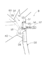
従来、竪型炉の原燃料装入装置として、本出願人が先に実公昭57−18427号公報で提示した竪型炉の原燃料装入装置Bがあり、その構造の概略を図5に示す。
図示するように、竪型炉50の鉄皮51の内面には、先部が竪型炉50の中心に向けて伸延する水平リンク52の基部が枢支連結されており、水平リンク52の先部には先部が下方に向けて伸延する垂直リンク53の基部が枢支連結され、リンク機構54が形成されている。垂直リンク53の先部の前面には、アーマープレート(又は反撥板)55が貼着されている。そして、この垂直リンク53の下部には水平押出棒56の先部が枢支連結されており、一方、水平押出棒56の基部は竪型炉50の鉄皮51の外面に取付けられている作動シリンダ57の伸縮ロッドに枢支連結されている。なお、図5において、58は炉体を示し、59は原料を示し、60は昇降自在なベルを示し、61は漏斗部を示し、62は既原料堆積部を示す。
前記した構成によって、作動シリンダ57を作動して水平押出棒56を進出すると、図5に示すように、垂直状態にあった反撥板55は点線で示すように急角度で内側に向けて傾斜することになる。従って、ベル60を下降させると、漏斗部61とベル60との間隙から原料59が外方に向けて傾斜面を滑りながら放射線状に落下して反撥板55に当接し、その後、落下方向を竪型炉50の内方に変更された後、炉体58の中央部に向けて放射線を描きながら落下することになる。
【0003】
【発明が解決しようとする課題】
しかしながら、前記した竪型炉の原燃料装入装置Bは、未だ、以下の解決すべき課題を有していた。
即ち、原料59は反撥板55によって反射されるため、既原料堆積部62に着地した際、原料は、垂直方向の力の成分のみならず、水平方向の力の成分を有するため、水平方向の流れ込みが生じ、所定の位置に正確に堆積するのが困難となる。
特に、本出願人が先に特願平8−31178号において提示した竪型炉へのダスト塊成鉱、自己還元性鉱塊、鉄屑、固体燃料等の原燃料装入方法においては、炉体の中央部と周辺部に異なった種類の原料や燃料を正確に充填する必要があるが、上記した竪型炉の原燃料装入装置Bでは、このような正確な充填は不可能となる。
本発明はかかる事情に鑑みてなされたもので、原燃料に水平力を与えずに竪型炉に装入することによって、銘柄の異なる複数の原燃料を炉体の所定の位置に正確に装入することができる竪型炉の原燃料装入装置及びその方法を提供することを目的とする。
【0004】
【課題を解決するための手段】
前記目的に沿う請求項1記載の竪型炉の原燃料装入装置は、竪型炉の炉頂部装入口の上方に昇降自在に設けられる上下端が開口された直円筒からなる貯留ホッパーの下端開口部に接離可能かつ昇降可能に設けられた円錐体からなるベルと、水平移動自在となって、前記竪型炉の炉体軸線を中心として半径方向に対称的に2又は3以上に分割され、下部がテーパー状に縮径して底部に排出口を備える原燃料ガイド部材とを備え、前記貯留ホッパーから投入される原燃料を炉内中央部とその周辺部に選択的に装入する切替えガイド装置を、前記竪型炉の炉頂部に設けている。
請求項2記載の竪型炉の原燃料装入装置は、請求項1記載の竪型炉の原燃料装入装置において、前記ベルの下端の直径を、前記炉内中央部の原燃料装入範囲の直径以上とし、前記原燃料ガイド部材の排出口の直径を、前記炉内中央部の原燃料装入範囲の直径以内としている。
請求項3記載の竪型炉の原燃料装入装置は、請求項1又は2に記載の竪型炉の原燃料装入装置において、前記ベルの下端及び/又は前記原燃料ガイド部材の排出口の下端に直筒部を設けている。
【0005】
そして、請求項4記載の竪型炉の原燃料装入方法は、前記請求項1〜3のいずれかに記載の原燃料装入装置を用いて、前記竪型炉の炉頂部装入口の上方に設けられる原燃料の前記貯留ホッパーからの原燃料を、前記炉内中央部とその周辺部に選択的に装入する竪型炉の原燃料装入方法において、前記炉内中央部の装入は、前記分割された原燃料ガイド部材を炉体軸線に対して半径方向移動して合体させ、下部をテーパー状に縮径した筒状の原燃料ガイド部材を形成し、前記炉頂部装入口に装着した後、前記貯留ホッパーに前記原燃料を供給し、該貯留ホッパーと該貯留ホッパーの下端開口部に設けたベルとを下降させて該貯留ホッパーの下端開口部を前記筒状の原燃料ガイド部材の上部に載置した後、前記ベルのみを下降させて前記原燃料を切り出し、前記筒状の原燃料ガイド部材内を流下させて前記炉内中央部に装入し、前記炉内周辺部の装入は、前記貯留ホッパーに前記原燃料を供給した後、待機位置にあって前記分割された原燃料ガイド部材の間に、該貯留ホッパーと該貯留ホッパーの下端開口部に設けたベルとを一体的に下降し、該貯留ホッパーを前記竪型炉の炉頂部装入口に載置した後、前記ベルのみを下降させて前記原燃料を放射状に切り出し、前記炉内周辺部に装入する。
請求項5記載の竪型炉の原燃料装入方法は、請求項4記載の竪型炉の原燃料装入方法において、前記炉内周辺部に燃料率の高い第1の原燃料(例えば炭材と金属化率(M.Fe/T.Fe)の低い鉄源の混合物、又は炭材)を装入し、前記炉内中央部に鉄源率の高い第2の原燃料(例えば金属化率(M.Fe/T.Fe)の高い鉄源及び浸炭用炭材)を装入する。
【0006】
【発明の実施の形態】
続いて、添付した図面を参照しつつ、本発明を具体化した実施の形態につき説明し、本発明の理解に供する。
まず、図1〜図3を参照して本発明の一実施の形態に係る竪型炉の原燃料装入装置Aの全体構成について説明する。
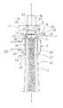
図示するように、竪型炉の原燃料装入装置Aは、竪型炉10の炉体11の上部に設けられ、実質的に、図示しない鉄皮によって外面を被覆されている炉体11の頂部に連設される筒状のガス回収フード12と、ガス回収フード12内に同心円的にかつ固定状態に配設される円筒部14と、この円筒部14の上方に昇降自在に配設される原燃料の貯留ホッパー15と、貯留ホッパー15の排出口を形成する下端開口部33に開閉弁として取付けられるベル16と、ガス回収フード12の上方に配設され炉体11の軸線X−Xを中心として半径方向に対称的に移動自在な左、右半割体17、18(それぞれ、原燃料ガイド部材片の一例)からなる原燃料ガイド部材19とを備え、前記円筒部14の上端部が炉頂部装入口を構成している。
【0007】
次に、前記した構成を有する竪型炉の原燃料装入装置Aの各部の構成について、図1〜図4を参照して具体的に説明する。
図示するように、断面円形の筒状のガス回収フード12の中央胴部20は、その上、下端部21、22より直径を大きくしており、下端部22は竪型炉10の炉体11の上端部23に気密状態に連設されている。なお、炉体11の上端部23はガス回収フード12の下端部22と略同一の直径を有する。また、ガス回収フード12の中央胴部20の一方にはガス排出口24が設けられており、ガス排出口24にはガス回収ダクト25がフランジを介して連結されている。
【0008】
ガス回収フード12内には、ガス回収フード12の上、下端部21、22と略等しい直径を有する円筒部14が同心円的にかつ固定状態に配設されている。即ち、円筒部14の上端開口部26はガス回収フード12の上端部21に連結されており、その下端開口部27は炉体11の上端部23に向けて伸延されている。そして、円筒部14の下端開口部27と炉体11の上端部23との間には、環状のガス流出路28が形成されている。
中央落下空間30は、円筒部14の直上に配設された左、右半割体17、18が合体した時の原燃料ガイド部材19の排出口13を上端とし、炉体11の中央部の上方に整合状態に位置されており、一方、周辺落下空間31は、中央落下空間30の周辺部に位置されている。
【0009】
図1〜図3に示すように、円筒部14の直上には、上下端が開口された直円筒からなる貯留ホッパー15が昇降自在に配設されている。
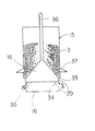
図1〜図4に示すように、貯留ホッパー15の下端開口部33には、円錐体からなるベル16が接離自在に取付けられている。ベル16の底部は左、右半割体17、18が合体した時に形成される原燃料ガイド部材19の排出口13と略同一面積を有している。
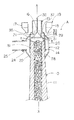
そして、図2に示すように、第1の原燃料aを下方装入位置にある貯留ホッパー15から周辺落下空間31を通して炉体11の周辺部に落下する場合には、ベル16は貯留ホッパー15の下端開口部33から少し下がった位置の円筒部14内に位置して、貯留ホッパー15の下端開口部33を開けた状態にしている。
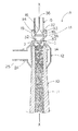
一方、図3に示すように、第2の原燃料bを上方装入位置にある貯留ホッパー15から中央落下空間30を通して炉体11の中央部に落下する場合には、ベル16は貯留ホッパー15と共に原燃料ガイド部材19内に位置される。
なお、前記昇降するベル16及び左右に分割される原燃料ガイド部材19を有して前述した切替えガイド装置が構成され、貯留ホッパー15から投入される原燃料b、aを炉内中央部とその周辺部に選択的に投入している。
【0010】
そして、貯留ホッパー15は、図3に示す状態では、ベル16と共に原燃料ガイド部材19内に位置される。また、この上方装入位置で、ベル16を貯留ホッパー15の下端開口部33から下方に離隔させることによって、図4に示すように、貯留ホッパー15の下端開口部33とベル16の原燃料滑走面34との間には、放射状切出口35が形成される。なお、前記したベル16と貯留ホッパー15の一体的な昇降動作、及び、貯留ホッパー15に対するベル16の相対的な下降動作は、ベル16の頂部に立設されたロッド36の上端部を、図示しないクレーン等を用いて昇降自在に吊支することによって容易に行うことができる。また、図1〜図4に示すように、貯留ホッパー15の下部外周面には載置ブラケット37が設けられており、この載置ブラケット37を介して、貯留ホッパー15は、図2に示す状態では、ガス回収フード12の上端部21に載置支持され、図3に示す状態では、原燃料ガイド部材19の上部に支持されることになる。
【0011】
図1〜図3に示すように、ガス回収フード12の上部には、半径方向に開閉自在な原燃料ガイド部材19が配設されている。即ち、原燃料ガイド部材19は、炉体11の軸線X−Xを中心として半径方向に対称的に水平移動自在な左、右半割体17、18からなり、下部がテーパー状に縮径している。左、右半割体17、18を移動させる装置は各種形態のものが考えられるが、例えば、ガス回収フード12の上端部21と略同じ高さを有する床面上に一対の走行台車を、炉体11の軸線X−Xを中心として左、右対称に移動自在に載置し、これらの走行台車に左、右半割体17、18をそれぞれ搭載することが考えられる。
これらの左、右半割体17、18は、図2に示すように、貯留ホッパー15が下方装入位置にある場合、左、右待機位置に位置されている。一方、図3に示すように、貯留ホッパー15が上方装入位置にある場合、即ち、ベル16及び貯留ホッパー15が上部位置にあり、中央落下空間30が確保された状態では、左、右半割体17、18が合体されて原燃料ガイド部材19が形成されることになる。この際、原燃料ガイド部材19は貯留ホッパー15の下部を囲繞すると共に、その下部内面には、貯留ホッパー15から切り出される第2の原燃料bを中央落下空間30内に流下させるための原燃料流下傾斜面38が形成されることになる。
なお、ベル16の下端の直径を、炉内中央部の原燃料装入範囲の直径以上とし、原燃料ガイド部材19の排出口13の直径を、炉内中央部の原燃料装入範囲の直径以内とするのが好ましい。また、本実施の形態では、原燃料ガイド部材19は2分割構造としたが、3分割構造あるいはそれ以上の分割構造とすることもできる。
【0012】
次に、前記した構成を有する竪型炉の原燃料装入装置Aによる竪型炉10の炉体11の原料の装入作業について説明する。なお、本実施の形態は、竪型炉10の炉体11内の周辺部に燃料率の高い第1の原燃料a(例えば、コークスとダスト塊成鉱)を、中央部に鉄源率の高い第2の原燃料b(例えば、スクラップ)を、それぞれ、装入する場合である。
まず、図2を参照して、切替えガイド装置を周辺装入に設定して、炉体11内の周辺部に第1の原燃料aを装入する場合について説明する。
左、右待機位置にある原燃料ガイド部材19の左、右半割体17、18間に、クレーン等を用いてベル16と貯留ホッパー15とを一体的に下降し、貯留ホッパー15を載置ブラケット37を介してガス回収フード12の上端部21上に載置する。クレーン等を用いてさらにベル16のみを下降し、ベル16によって中央落下空間30を閉じると共に、貯留ホッパー15の下端開口部33とベル16の原燃料滑走面34との間に放射状切出口35を形成する。
これによって、貯留ホッパー15内に貯留されていた第1の原燃料aは、原燃料滑走面34に沿って放射状に流下して周辺落下空間31内に流入される。その後、第1の原燃料aは、周辺落下空間31内で、ベル下端直筒部29と円筒部14の内周面とによって整流作用を受ける。従って、第1の原燃料aは、水平方向成分は消失した状態で炉体11内の周辺部に垂直に落下する。このように、第1の原燃料aが水平方向に飛散するのを確実に防止できるので、第1の原燃料aを正確かつ確実に炉体11内の周辺部に堆積することができる。
【0013】
次に、図3を参照して、切替えガイド装置を中心装入に設定して、炉体11の中央部に第2の原燃料bを装入する場合について説明する。
図示するように、左、右半割体17、18を炉体11の軸線X−Xに対して半径方向移動して合体させ、筒状の原燃料ガイド部材19を形成して、炉頂部装入口に装着した後、クレーン等を用いて貯留ホッパー15とベル16とを下降して、貯留ホッパー15を載置ブラケット37を介して原燃料ガイド部材19の上面に載置する。
これによって、貯留ホッパー15の下部とベル16とは原燃料ガイド部材19によって囲繞されることになる。次に、クレーン等を用いてベル16のみを下降し、貯留ホッパー15の下端開口部33とベル16の原燃料滑走面34との間に放射状切出口35を形成すると、貯留ホッパー15内に貯留されていた第2の原燃料bは、原燃料滑走面34に沿って放射状に流下して原燃料ガイド部材19の原燃料流下傾斜面38に当接した後、この原燃料流下傾斜面38に沿って炉体11の軸線X−Xに向けて流下し、原燃料ガイド部材19の下端の直筒部32で整流作用を受ける。従って、第2の原燃料bも、水平方向成分は消失した状態で炉体11の中央部、即ち、炉内中央部に垂直に落下することになる。このように、第2の原燃料bが水平方向に飛散するのを確実に防止できるので、第2の原燃料bを正確かつ確実に炉体11の中央部に堆積することができる。
このように、本実施の形態では、内容の異なる複数の原燃料a、bを炉体11内の所定位置に正確かつ確実に装入することができる。
【0014】
特に、本実施の形態では、炉体11の頂部に連設されるガス回収フード12内に同心円的にかつ固定状態に円筒部14が配設され、円筒部14の上方に貯留ホッパー15が昇降自在に配設され、貯留ホッパー15の下端開口部33には第1の原燃料aを周辺落下空間31に向けて流下させる原燃料滑走面34を有するベル16が上下方向に接離自在に取付けられ、かつ、ガス回収フード12の上方には、炉体11の軸線X−Xを中心として半径方向に対称的に移動自在な左、右半割体17、18からなる原燃料ガイド部材19が配設されており、原燃料ガイド部材19の下部内面には第2の原燃料bを中央落下空間30に向けて流下させる原燃料流下傾斜面38が形成されている。
従って、貯留ホッパー15内に供給される第1及び第2の原燃料a、bを、貯留ホッパー15から炉体11内の周辺部と中央部に向けて、それぞれ、殆ど直線状に落下することができるので棚掛現象を防止でき、これらの原燃料a、bの装入作業を、正確、確実かつ円滑に行うことができる。
以上、本発明を、一実施の形態を参照して説明してきたが、本発明は何ら前記した実施の形態に記載の構成に限定されるものではなく、特許請求の範囲に記載されている事項の範囲内で考えられるその他の実施の形態や変容例も含むものである。
【0015】
【発明の効果】
請求項1〜3記載の竪型炉の原燃料装入装置及び請求項4及び5記載の竪型炉の原燃料装入方法においては、貯留ホッパーから投入される原燃料を炉内中央部とその周辺部に選択的に装入する切替えガイド装置を、竪型炉の炉頂部に設けたので、竪型炉の原燃料の投入を中央部とその周辺部に区別して正確に投入することができる。
従って、貯留ホッパー内に供給される複数の原燃料を、貯留ホッパーから炉体内の所定箇所に向けて、それぞれ、殆ど直線状に落下することができるので棚掛現象を防止でき、これらの原料の装入作業を、正確、確実かつ円滑に行うことができる。
また、切替えガイド装置が、貯留ホッパーの下端開口部に昇降可能に設けられたベルと、貯留ホッパーと炉頂部装入口との間に着脱可能に設けられ、テーパー状に下部が縮径して底部に排出口を備える筒状の原燃料ガイド部材とを備えているので、昇降するベル付きの貯留ホッパーをそのまま使用し、原燃料ガイド部材を使用する場合と使用しない場合とで、炉内中央部とその周辺部に投入位置を簡便に切り換えることができる。
さらに、原燃料ガイド部材が、複数区分に縦割可能な構造となって、分割された原燃料ガイド部材が水平移動して、炉頂部装入口に着脱自在となっているので、原燃料ガイド部材の炉頂部への装着が容易となり、装置の簡略化が図れる。
請求項2記載の竪型炉の原燃料装入装置においては、ベルの下端の直径を、炉内中央部の原燃料装入範囲の直径以上とし、原燃料ガイド部材の排出口の直径を、炉内中央部の原燃料装入範囲の直径以内としているので、投入する原燃料の落下位置が正確に制御できる。
【0016】
請求項3記載の竪型炉の原燃料装入装置においては、ベルの下端及び/又は原燃料ガイド部材の排出口の下端に直筒部を設けることによって、原燃料の落下を安定させることができる他、ベルの下端及び/又は原燃料ガイド部材の排出口の早期磨耗を防止できる。
更には特に、請求項5記載の竪型炉の原燃料装入方法においては、切替えガイド装置を用いて、貯留ホッパーからの燃料率の高い第1の原燃料を炉内周辺部に正確に投入し、鉄源率の高い第2の原燃料を炉内中央部に正確に投入することができる。これによって、竪型炉の安定操業を行うことができる。
貯留ホッパーの下端開口部に設けたベルを介して第1の原燃料を放射状に切り出しているので、炉内周辺部に均等に投入され、また、更にベルから放射状に投入された第2の原燃料を下方の縮径する原燃料ガイド部材を介して中央に集めて炉内に投入しているので、炉内中央部に集中的に第2の原燃料が投入される。この場合、原燃料ガイド部材を使用するか否かで、それぞれ原燃料の投入位置が決められることになる。
そして、原燃料ガイド部材を予め縦割しておき、これらを水平移動して所定位置に組み立てるようにしているので、貯留ホッパーを所定位置に配置した状態で、原燃料ガイド部材の操作が行え、その制御が簡略化される。
【図面の簡単な説明】
【図1】本発明の一実施の形態に係る竪型炉の原燃料装入装置の全体構成説明図である。
【図2】本発明の一実施の形態に係る第1の原燃料を装入する際の竪型炉の原燃料装入装置の全体構成説明図である。
【図3】本発明の一実施の形態に係る第2の原燃料を装入する際の竪型炉の原燃料装入装置の全体構成説明図である。
【図4】貯留ホッパーとベルの拡大正面図である。
【図5】従来の竪型炉の原燃料装入装置の要部構成拡大説明図である。
【符号の説明】
A 竪型炉の原燃料装入装置 a 第1の原燃料
b 第2の原燃料 10 竪型炉
11 炉体 12 ガス回収フード
13 排出口 14 円筒部
15 貯留ホッパー 16 ベル
17 左半割体 18 右半割体
19 原燃料ガイド部材 20 中央胴部
21 上端部 22 下端部
23 上端部 24 ガス排出口
25 ガス回収ダクト 26 上端開口部
27 下端開口部 28 ガス流出路
29 ベル下端直筒部 30 中央落下空間
31 周辺落下空間 32 直筒部
33 下端開口部 34 原燃料滑走面
35 放射状切出口 36 ロッド
37 載置ブラケット 38 原燃料流下傾斜面[0001]
TECHNICAL FIELD OF THE INVENTION
The present invention relates to an apparatus and a method for charging raw fuel for a vertical furnace used for charging raw fuel into a vertical furnace such as a blast furnace, a cupola furnace, and a melting furnace.
[0002]
[Prior art]
Conventionally, as a raw fuel charging apparatus for a vertical furnace, there is a raw fuel charging apparatus B for a vertical furnace which the present applicant has previously presented in Japanese Utility Model Publication No. 57-18427, and the structure thereof is schematically shown in FIG. Show.
As shown in the figure, the base of a
With the above-described configuration, when the operating
[0003]
[Problems to be solved by the invention]
However, the above-described raw fuel charging apparatus B for a vertical furnace still has the following problems to be solved.
That is, since the
In particular, in the method of charging raw fuel such as dust agglomerate, self-reducing ore, iron scrap, and solid fuel into a vertical furnace, which the present applicant has previously proposed in Japanese Patent Application No. 8-31178. It is necessary to precisely fill the center and periphery of the body with different types of raw materials and fuels, but with the above-described raw material charging apparatus B for a vertical furnace, such accurate filling becomes impossible. .
The present invention has been made in view of the above circumstances, and by loading a raw fuel into a vertical furnace without applying a horizontal force to the raw fuel, a plurality of raw fuels having different brands are accurately loaded at predetermined positions of the furnace body. It is an object of the present invention to provide an apparatus and a method for charging raw fuel of a vertical furnace which can be charged.
[0004]
[Means for Solving the Problems]
The raw fuel charging apparatus of the vertical furnace according to claim 1, wherein along the object, the lower end of the reservoir hopper top and bottom ends provided vertically movably above the furnace top BuSo inlet of the shaft furnace is made of a straight cylinder which is open A bell made of a conical body that can be moved toward and away from the opening and that can be moved up and down, and is horizontally movable and divided into two or more parts symmetrically in the radial direction about the furnace body axis of the vertical furnace A raw fuel guide member having a tapered lower portion and a discharge port at the bottom, and selectively charging raw fuel supplied from the storage hopper into a central portion in the furnace and a peripheral portion thereof. the switching guide device is provided on the furnace top portion of the shaft furnace.
Claim 2 raw fuel charging apparatus of the vertical furnace according, in raw fuel charging apparatus of the vertical furnace according to claim 1, wherein the diameter of the lower end of the bell, raw fuel charging of the furnace central portion The diameter of the outlet of the raw fuel guide member is set to be equal to or larger than the diameter of the raw fuel charging range in the central part of the furnace.
The raw fuel charging apparatus for a vertical furnace according to claim 3 is the raw fuel charging apparatus for a vertical furnace according to claim 1 or 2 , wherein the lower end of the bell and / or the outlet of the raw fuel guide member. Is provided with a straight cylindrical portion at the lower end.
[0005]
A raw fuel charging method for a vertical furnace according to a fourth aspect of the present invention uses the raw fuel charging apparatus according to any one of the first to third aspects , wherein the raw fuel charging apparatus is provided above the furnace top charging inlet of the vertical furnace. in the raw fuel from the reservoir hopper, the furnace central portion and the raw fuel charging method of the vertical furnace for selectively charged into the peripheral portion of the raw fuel provided, charging of the furnace central portion Is moved in the radial direction with respect to the furnace body axis and united the divided raw fuel guide member, forming a cylindrical raw fuel guide member having a tapered lower portion at the lower portion, and at the furnace top charging inlet After mounting, the raw fuel is supplied to the storage hopper, and the storage hopper and the bell provided at the lower end opening of the storage hopper are lowered to lower the lower end opening of the storage hopper into the cylindrical raw fuel guide. After placing on the top of the member, only the bell is lowered to remove the raw fuel. The raw fuel flows down through the cylindrical raw fuel guide member and is charged into the central part of the furnace. The peripheral part of the furnace is charged at the standby position after supplying the raw fuel to the storage hopper. The storage hopper and a bell provided at the lower end opening of the storage hopper are integrally lowered between the divided raw fuel guide members, and the storage hopper is mounted on the furnace top of the vertical furnace. After being placed at the entrance, only the bell is lowered to radially cut out the raw fuel, and the raw fuel is charged into the peripheral part in the furnace.
According to a fifth aspect of the present invention, there is provided a method for charging raw fuel in a vertical furnace according to the fourth aspect, wherein the first raw fuel having a high fuel rate (for example, A mixture of a raw material and an iron source having a low metallization ratio (M.Fe / T.Fe) or a carbon material) is charged, and a second raw fuel having a high iron source ratio (for example, An iron source having a high ratio (M.Fe / T.Fe) and a carbon material for carburizing) are charged.
[0006]
BEST MODE FOR CARRYING OUT THE INVENTION
Next, embodiments of the present invention will be described with reference to the accompanying drawings to provide an understanding of the present invention.
First, an overall configuration of a raw fuel charging apparatus A for a vertical furnace according to an embodiment of the present invention will be described with reference to FIGS.
As shown in the figure, a raw material charging device A for a vertical furnace is provided on an upper part of a furnace body 11 of a
[0007]
Next, the configuration of each part of the raw fuel charging apparatus A for a vertical furnace having the above-described configuration will be specifically described with reference to FIGS.
As shown in the figure, the
[0008]
Inside the
The
[0009]
As shown in FIGS. 1 to 3, a
As shown in FIGS. 1 to 4, a
As shown in FIG. 2, when the first raw fuel a falls from the
On the other hand, as shown in FIG. 3, when the second raw fuel b falls from the
The switching guide device described above is configured to have the
[0010]
The
[0011]
As shown in FIGS. 1 to 3, a raw
These left and
The diameter of the lower end of the
[0012]
Next, the charging operation of the raw material of the furnace body 11 of the
First, a case in which the switching guide device is set to peripheral charging and the first raw fuel a is charged into the peripheral portion in the furnace body 11 will be described with reference to FIG.
The
Thereby, the first raw fuel a stored in the
[0013]
Next, a case where the switching guide device is set to the central charging and the second raw fuel b is charged into the central portion of the furnace body 11 will be described with reference to FIG.
As shown in the figure, the left and
Thus, the lower part of the
As described above, in the present embodiment, a plurality of raw fuels a and b having different contents can be accurately and reliably charged into a predetermined position in the furnace body 11.
[0014]
In particular, in the present embodiment, the
Therefore, the first and second raw fuels a and b supplied into the
As described above, the present invention has been described with reference to one embodiment. However, the present invention is not limited to the configuration described in the above-described embodiment, and is described in the claims. Other embodiments and modifications that can be considered within the scope of the present invention are also included.
[0015]
【The invention's effect】
In the apparatus for charging raw fuel for a vertical furnace according to claims 1 to 3 and the method for charging raw fuel for a vertical furnace according to claims 4 and 5 , the raw fuel supplied from a storage hopper is placed in a central part of the furnace. A switching guide device for selectively charging the periphery of the furnace is provided at the furnace top of the vertical furnace, so that the supply of raw fuel for the vertical furnace can be accurately distinguished between the central part and the periphery. it can.
Therefore, a plurality of raw fuels supplied into the storage hopper can be almost linearly dropped from the storage hopper toward a predetermined position in the furnace, respectively, so that a shelving phenomenon can be prevented. The charging operation can be performed accurately, reliably and smoothly.
Further, a switching guide device is provided detachably between a bell provided at the lower end opening of the storage hopper so as to be able to move up and down, and a storage hopper and a furnace top inlet, and the lower portion is tapered at the lower portion to reduce the diameter of the bottom portion. And a cylindrical raw fuel guide member having a discharge port, so that the storage hopper with a bell that goes up and down can be used as it is, and when the raw fuel guide member is used and not used, the central part of the furnace And the surroundings can be easily switched to the input position.
Further, the raw fuel guide member has a structure that can be vertically divided into a plurality of sections, and the divided raw fuel guide member moves horizontally and is detachably attached to the furnace top charging port. Can be easily mounted on the furnace top, and the apparatus can be simplified.
In the raw fuel charging apparatus for a vertical furnace according to claim 2, the diameter of the lower end of the bell is set to be equal to or larger than the diameter of the raw fuel charging range in the central part of the furnace, and the diameter of the outlet of the raw fuel guide member is Since the diameter of the raw fuel is not more than the diameter of the raw fuel charging range in the central part of the furnace, the falling position of the raw fuel to be charged can be accurately controlled.
[0016]
In the raw fuel charging apparatus for a vertical furnace according to the third aspect, by providing a straight cylindrical portion at the lower end of the bell and / or the lower end of the discharge port of the raw fuel guide member, the falling of the raw fuel can be stabilized. In addition, it is possible to prevent premature wear of the lower end of the bell and / or the outlet of the raw fuel guide member.
Furthermore, in particular, in the raw fuel charging method for a vertical furnace according to the fifth aspect, the first raw fuel having a high fuel rate from the storage hopper is accurately charged into the periphery of the furnace by using the switching guide device. In addition, the second raw fuel having a high iron source rate can be accurately injected into the central part of the furnace. Thereby, the stable operation of the vertical furnace can be performed.
Since the first raw fuel is radially cut out through the bell provided at the lower end opening of the storage hopper, the first raw fuel is uniformly injected into the furnace inner peripheral portion, and furthermore, the second raw fuel is radially injected from the bell. Since the fuel is collected at the center via the raw fuel guide member for reducing the diameter of the fuel and injected into the furnace, the second raw fuel is intensively injected into the center of the furnace. In this case, the input position of the raw fuel is determined depending on whether or not the raw fuel guide member is used.
And, the raw fuel guide members are vertically divided in advance, and they are horizontally moved and assembled at a predetermined position, so that the raw fuel guide members can be operated with the storage hopper arranged at the predetermined position, The control is simplified.
[Brief description of the drawings]
FIG. 1 is an explanatory diagram of the entire configuration of a raw fuel charging apparatus for a vertical furnace according to an embodiment of the present invention.
FIG. 2 is an explanatory diagram of the entire configuration of a raw fuel charging apparatus for a vertical furnace when charging a first raw fuel according to an embodiment of the present invention.
FIG. 3 is an explanatory view of the entire configuration of a raw fuel charging apparatus for a vertical furnace when charging a second raw fuel according to an embodiment of the present invention.
FIG. 4 is an enlarged front view of a storage hopper and a bell.
FIG. 5 is an enlarged explanatory view of a main part configuration of a conventional raw fuel charging apparatus for a vertical furnace.
[Explanation of symbols]
Reference Signs List A Raw fuel charging device for vertical furnace a First raw fuel b Second
Claims (5)
Priority Applications (1)
| Application Number | Priority Date | Filing Date | Title |
|---|---|---|---|
| JP09147197A JP3586355B2 (en) | 1997-03-25 | 1997-03-25 | Raw fuel loading apparatus and method for vertical furnace |
Applications Claiming Priority (1)
| Application Number | Priority Date | Filing Date | Title |
|---|---|---|---|
| JP09147197A JP3586355B2 (en) | 1997-03-25 | 1997-03-25 | Raw fuel loading apparatus and method for vertical furnace |
Publications (2)
| Publication Number | Publication Date |
|---|---|
| JPH10267538A JPH10267538A (en) | 1998-10-09 |
| JP3586355B2 true JP3586355B2 (en) | 2004-11-10 |
Family
ID=14027318
Family Applications (1)
| Application Number | Title | Priority Date | Filing Date |
|---|---|---|---|
| JP09147197A Expired - Fee Related JP3586355B2 (en) | 1997-03-25 | 1997-03-25 | Raw fuel loading apparatus and method for vertical furnace |
Country Status (1)
| Country | Link |
|---|---|
| JP (1) | JP3586355B2 (en) |
Cited By (1)
| Publication number | Priority date | Publication date | Assignee | Title |
|---|---|---|---|---|
| WO2009031367A1 (en) | 2007-09-07 | 2009-03-12 | Nippon Steel Corporation | Vertical furnace |
-
1997
- 1997-03-25 JP JP09147197A patent/JP3586355B2/en not_active Expired - Fee Related
Cited By (1)
| Publication number | Priority date | Publication date | Assignee | Title |
|---|---|---|---|---|
| WO2009031367A1 (en) | 2007-09-07 | 2009-03-12 | Nippon Steel Corporation | Vertical furnace |
Also Published As
| Publication number | Publication date |
|---|---|
| JPH10267538A (en) | 1998-10-09 |
Similar Documents
| Publication | Publication Date | Title |
|---|---|---|
| AU748255B2 (en) | Continuous charge preheating, melting, refining and casting | |
| US5343492A (en) | Closed induction furnace for the melting and casting of substances | |
| US20010055739A1 (en) | Compact continuous charging apparatus | |
| JP2756602B2 (en) | Charging equipment for blast furnace | |
| US5263689A (en) | Apparatus for making alloy power | |
| KR101252646B1 (en) | Pig casting machine and method for manufacturing cold pig iron using the same | |
| JP3586355B2 (en) | Raw fuel loading apparatus and method for vertical furnace | |
| CS216824B2 (en) | Facility for dosing the fine grained material | |
| KR101850659B1 (en) | Apparatus for supplying recarburizer of electric furnace using tire powder and supplying method thereof | |
| JPH0480086B2 (en) | ||
| JPH03247716A (en) | Device for removing dust attached to the bottom surface of the dispersion plate of the pre-reduction furnace in melt reduction equipment | |
| JPH09509734A (en) | Charging device for arc furnace | |
| US3253723A (en) | Method of and apparatus for charging scrap | |
| US4451925A (en) | Charging system for electric arc furnaces | |
| US2982534A (en) | Rotary furnace apparatus | |
| US5497977A (en) | Process and apparatus for preheating and inserting scrap into a smelting furnace | |
| JPH10267539A (en) | Vertical furnace charging equipment | |
| JP2012132056A (en) | Top bunker of blast furnace | |
| JP3756642B2 (en) | Sorting and charging equipment for the center of the blast furnace | |
| CN223660156U (en) | Slag charge device of electroslag furnace | |
| US3796326A (en) | Cupola furnace having a closure arrangement | |
| JPS5933163B2 (en) | Variable raw material distribution device for blast furnace | |
| JPH05179337A (en) | Method and apparatus for charging heat insulating material into molten steel ladle | |
| JP3572781B2 (en) | Central charging equipment for blast furnace raw materials | |
| JP7063635B2 (en) | Wire loading station in steelmaking methods and systems |
Legal Events
| Date | Code | Title | Description |
|---|---|---|---|
| A131 | Notification of reasons for refusal |
Free format text: JAPANESE INTERMEDIATE CODE: A131 Effective date: 20040406 |
|
| A521 | Written amendment |
Free format text: JAPANESE INTERMEDIATE CODE: A523 Effective date: 20040604 |
|
| TRDD | Decision of grant or rejection written | ||
| A01 | Written decision to grant a patent or to grant a registration (utility model) |
Free format text: JAPANESE INTERMEDIATE CODE: A01 Effective date: 20040727 |
|
| A61 | First payment of annual fees (during grant procedure) |
Free format text: JAPANESE INTERMEDIATE CODE: A61 Effective date: 20040806 |
|
| FPAY | Renewal fee payment (event date is renewal date of database) |
Free format text: PAYMENT UNTIL: 20080813 Year of fee payment: 4 |
|
| FPAY | Renewal fee payment (event date is renewal date of database) |
Free format text: PAYMENT UNTIL: 20090813 Year of fee payment: 5 |
|
| FPAY | Renewal fee payment (event date is renewal date of database) |
Free format text: PAYMENT UNTIL: 20090813 Year of fee payment: 5 |
|
| FPAY | Renewal fee payment (event date is renewal date of database) |
Free format text: PAYMENT UNTIL: 20100813 Year of fee payment: 6 |
|
| FPAY | Renewal fee payment (event date is renewal date of database) |
Free format text: PAYMENT UNTIL: 20100813 Year of fee payment: 6 |
|
| FPAY | Renewal fee payment (event date is renewal date of database) |
Free format text: PAYMENT UNTIL: 20110813 Year of fee payment: 7 |
|
| FPAY | Renewal fee payment (event date is renewal date of database) |
Free format text: PAYMENT UNTIL: 20120813 Year of fee payment: 8 |
|
| FPAY | Renewal fee payment (event date is renewal date of database) |
Free format text: PAYMENT UNTIL: 20130813 Year of fee payment: 9 |
|
| FPAY | Renewal fee payment (event date is renewal date of database) |
Free format text: PAYMENT UNTIL: 20130813 Year of fee payment: 9 |
|
| S531 | Written request for registration of change of domicile |
Free format text: JAPANESE INTERMEDIATE CODE: R313531 |
|
| FPAY | Renewal fee payment (event date is renewal date of database) |
Free format text: PAYMENT UNTIL: 20130813 Year of fee payment: 9 |
|
| R350 | Written notification of registration of transfer |
Free format text: JAPANESE INTERMEDIATE CODE: R350 |
|
| FPAY | Renewal fee payment (event date is renewal date of database) |
Free format text: PAYMENT UNTIL: 20130813 Year of fee payment: 9 |
|
| S533 | Written request for registration of change of name |
Free format text: JAPANESE INTERMEDIATE CODE: R313533 |
|
| FPAY | Renewal fee payment (event date is renewal date of database) |
Free format text: PAYMENT UNTIL: 20130813 Year of fee payment: 9 |
|
| R350 | Written notification of registration of transfer |
Free format text: JAPANESE INTERMEDIATE CODE: R350 |
|
| LAPS | Cancellation because of no payment of annual fees |