JP3585102B2 - Cartridge insertion / ejection device - Google Patents
Cartridge insertion / ejection device Download PDFInfo
- Publication number
- JP3585102B2 JP3585102B2 JP25791799A JP25791799A JP3585102B2 JP 3585102 B2 JP3585102 B2 JP 3585102B2 JP 25791799 A JP25791799 A JP 25791799A JP 25791799 A JP25791799 A JP 25791799A JP 3585102 B2 JP3585102 B2 JP 3585102B2
- Authority
- JP
- Japan
- Prior art keywords
- cartridge
- drive arm
- arm member
- elastic member
- cartridge container
- Prior art date
- Legal status (The legal status is an assumption and is not a legal conclusion. Google has not performed a legal analysis and makes no representation as to the accuracy of the status listed.)
- Expired - Fee Related
Links
Images


Description
【0001】
【発明の属する技術分野】
本発明は、カートリッジ挿入排出装置に係り、より詳細には記憶媒体を収納したカートリッジを記録再生装置の本体内に挿入および排出するカートリッジ挿入排出装置に関する。
【0002】
【従来の技術】
従来、記憶媒体を収納したMD、FD、MOなどのカートリッジは、記録再生装置の本体内に挿入して記録再生位置に移動させることで、所定の情報を記録再生する。この際、記録再生装置の本体内には、カートリッジを記録再生位置に挿入および排出するカートリッジ挿入排出装置が設けられている。
【0003】
図11は、このようにMD記録再生装置に採用した従来のカートリッジ挿入排出装置を示す斜視図である。また、図12は、図11に示した牽引部60を示す斜視図である。また、図13は、図12に示したカートリッジコンテナ62の詳細を示す一部切り欠いた斜視図である。また、図14は、図11に示したMDカートリッジ1を記録再生位置に移動した状態を示す図である。また、図15は、図11に示した駆動アーム部材70の動作を示す動作説明図であり、図15(a)は排出状態を、図15(b)はMDカートリッジ1を挿入した状態を、図15(c)は記録再生位置に移動した状態を各々示している。また、図16は、図12に示した弾性部材66の動作を示す動作説明図であり、図16(a)は排出時の状態を、図16(b)はMDカートリッジ1挿入時の状態を、図16(c)はMDカートリッジ1挿入後の状態を各々示している。
【0004】
図11に示すように、MD記録再生装置に採用した従来のカートリッジ挿入排出装置は、MDカートリッジ1を挿入して記録再生する記録再生装置の本体50内に設けられており、この本体50内に挿入したMDカートリッジ1を保持して挿入排出方向に摺動するように形成した牽引部60と、この牽引部60をMDカートリッジ1の挿入排出方向に摺動させる駆動アーム部材70と、この駆動アーム部材70の動作に合わせて牽引部60を記録再生位置に上下動させる昇降部80とを備えている。
【0005】
ここで、記録再生装置の本体50内には、底部にMDカートリッジ1を挿入して所定の情報を記録再生する光ピックアップ、ターンテーブルなどの記録再生部品(図示せず)を配置した記録再生面52を備えている。そして、この記録再生面52には、回転軸70aを中心に回転可能に軸支された駆動アーム部材70と、この駆動アーム部材70の両側で回転可能に軸支された昇降部80とが支持されている。この駆動アーム部材70と昇降部80とは、図示されていないが、モータ、ギヤ、カムなどの駆動源に接続して動力を伝達され、ある決まったタイミングで回転動作を実行するように形成されている。
また、昇降部80は、牽引部60の両側に係合して回転軸82aを中心に回転することで牽引部60を上下動させる回転アーム82と、MDカートリッジ1の排出時に牽引部60を固定するロック部材84と、このロック部材84が弾性係合して固定される係合部86とにより形成されている。
【0006】
また、牽引部60は、図12に示すように、薄板状に形成されて両側面をほぼ直角に屈曲させたローディングシャシ64と、このローディングシャシ64内でMDカートリッジ1を保持して挿入排出方向に摺動するカートリッジコンテナ62とにより形成されている。ここで、ローディングシャシ64には、表面に細長く開口して平行に延在する2つの軌道溝64a、64bを形成している。また、カートリッジコンテナ62には、上面に突出する3つのガイドピン62a、62b、62cを備えている。そして、カートリッジコンテナ62は、ローディングシャシ64の内部からガイドピン62a、62b、62cを軌道溝64a、64bに係合するとともに、図示されていないローラを結合することで摺動可能に装着されている。また、ローディングシャシ64には、軌道溝64aの近傍に一端を固定し、他端を軌道溝64aを介してカートリッジコンテナ62に装着されたコイルバネ形状の弾性部材66を設けている。これによりカートリッジコンテナ62は、弾性部材66の付勢により常に所定の方向に付勢されている。
【0007】
また、MDカートリジ1には、両側に底面から凹状に開口する2つの牽引用溝部1a、1bを設けている。この牽引用溝部1a、1bは、図13に示すように、カートリッジコンテナ62の一端側に保持部62d、62eを設け、MDカートリッジ1をカートリッジコンテナ62に挿入した際に牽引用溝部1a、1bに保持部62d、62eに係合するように形成している。また、カートリッジコンテナ62には、MDカートリッジ1の後端に板状に延在して略L字に屈曲した凹状の係合凹部62fを一体に形成している。この係合凹部62fは、駆動アーム部材70の係合凸部70b(図15参照)が係合して回転することでカートリッジコンテナ62を摺動できるように設けてある。
【0008】
再び図11を参照して、このように形成された従来のカートリッジ挿入排出装置は、MDカートリジ1を牽引部60に挿入すると、駆動アーム部材70が回転軸70aを中心にして回転し、カートリッジコンテナ62とMDカートリジ1とを牽引部60内に摺動させる。その後、回転アーム82が回転軸82aを中心に回転して牽引部60を、図14に示すように、降下させてMDカートリジ1を記録再位面52の記録再位置に位置決めする。この際、ロック部材84は、MDカートリジ1が位置決されると同時に係合部86との弾性係合が解除される。
【0009】
また、駆動アーム部材70は、図15(a)に示すように、排出待機位置において停止しているMDカートリッジ1を挿入方向に押すと、カートリッジコンテナ62が駆動アーム部材70を回転させて開始検出スイッチ(図示せず)を押すことによりMDカートリッジ1のローディング動作が始まる。そして、駆動アーム部材70は、回転軸70aを中心に回転することで係合凹部62fに係合凸部70bを係合してカートリッジコンテナ62を摺動させてMDカートリジ1を図15(b)に示すように牽引部60内(図示されないターンテーブルの略上方)に収納する。
【0010】
この際、駆動アーム部材70の係合凸部70bは、カートリッジコンテナ62の係合凹部62fに遊びJ(駆動アーム部材70が牽引できない分)を設けている。この遊びJは、係合凸部70bと係合凹部62fとの係合を確実にし、余裕のある構造に形成するために設けてある。そして、牽引部60内にMDカートリジ1が収納されると、図11に示した回転アーム82が回転して牽引部60を図15(c)に示すように記録再生位置に降下させる。この際、係合凸部70bと係合凹部62fとの間に前述した遊びJを設けることで、駆動アーム部材70の係合凸部70bとカートリッジコンテナ62の係合凹部62fとの係合が容易に外れて牽引部60を降下させることができる。
【0011】
また、カートリッジコンテナ62は、駆動アーム部材70により摺動する場合、常に弾性部材66(図12参照)により所定の方向に付勢している。この弾性部材66は、カートリッジコンテナ62を容易に摺動するために設けているとともに、前述した遊びJを吸収するために設けてある。この弾性部材66は、図16(a)に示すように、カートリッジコンテナ62が排出待機位置にある場合、このカートリッジコンテナ62を常に排出方向に付勢している。そして、この弾性部材66は、カートリッジコンテナ62が駆動アーム部材70により摺動すると、図16(b)に示すように、牽引部60のほぼ中心位置でカートリッジコンテナ62に付勢力がかからない中立状態になる。また、弾性部材66は、カートリッジコンテナ62が更に摺動すること、図16(c)に示すように、カートリッジコンテナ62をMDカートリジ1の挿入方向に付勢してチャッキング待機位置に待機させる。これによりカートリッジコンテナ62は、弾性部材66により図15(b)に示した遊びJを挿入方向に吸収して、図15(c)示したように確実に降下して記録再生面52に位置決めされる。
このように、従来のカートリッジ挿入排出装置は、MDカートリジ1を挿入したカートリッジコンテナ62を弾性部材66により排出位置からチャッキング待機位置に付勢力が作用するように設け、確実に記録再生面52に降下して位置決めするように形成していた。
【0012】
【発明が解決しようとする課題】
しかしながら、従来のカートリッジ挿入排出装置では、図16(b)に示した中立状態の弾性部材66が図16(c)に示した挿入方向の付勢に切り替わる際、弾性部材66の反力によりカートリッジコンテナ62の摺動速度が加速されてチャッキング待機位置で衝撃によりMDカートリッジ1がカートリッジコンテナ62から外れてしまうため、図13に示した保持部62d、62eの保持力を強くする必要があった。このように保持部62d、62eの保持力を強くした場合、MDカートリッジ1をカートリッジコンテナ62に挿入する挿入力が増加して挿入感が悪くなるという不具合があった。
【0013】
また、従来のカートリッジ挿入排出装置では、図16(b)に示した中立状態の弾性部材66が図16(a)及び図16(b)に示した排出方向または挿入方向いずれかの付勢力に変わってカートリッジコンテナ62を摺動させて停止する際、加速による衝撃音が発生してしまう。また、この衝撃音を吸収するために衝撃吸収材などの構造を採用すると、製品全体のコストが高くなるという不具合があった。
【0014】
さらに、従来のカートリッジ挿入排出装置では、図16(b)に示したように特に弾性部材66が中立状態にある場合、図11に示したMDカートリッジ1の挿入方向と直交する上下方向に弾性部材66が動いて変位するため、本体50内の部品が弾性部材66と当接しないように形成することで本体50の上下方向の厚みが厚くなり大型化してしまうという不具合や、当接しないよう本装置との配設部品に考慮する必要があった。
本発明はこのような課題を解決し、摺動動作の衝撃による衝撃音及びカートリッジの外れを防止し、録再生位置に確実に位置決め可能なカートリッジ挿入排出装置を提供することを目的とする。
【0015】
【課題を解決するための手段】
本発明は上述の課題を解決するために、記憶媒体を収納したカートリッジを挿入してローディングする本体と、この本体内に挿入したカートリッジを保持して挿入排出方向に摺動可能に形成されたカートリッジコンテナ及びこのカートリッジコンテナを挿入排出方向に摺動可能に支持するローディングシャシを備えた牽引部と、このカートリッジコンテナに係合してカートリッジの挿入排出方向に摺動させる駆動アーム部材と、本体内でローディングシャシと係合して駆動アーム部材の動作に合わせてローディングシャシを上下動させてローディング位置に位置決めする昇降部とを備え、カートリッジコンテナの挿入方向後端に凹状の係合凹部を形成して駆動アーム部材を係合させるとともに、この係合凹部に設けられて駆動アーム部材に当接して上方向と排出方向とに常に付勢する弾性部材を設ける。
【0016】
ここで、弾性部材は、カートリッジコンテナの係合凹部に一端を固定して他端を駆動アーム部材に当接させることで付勢するコイルバネであることが好ましい。また、弾性部材は、カートリッジコンテナの係合凹部に一体形成した板バネを駆動アーム部材に当接させることで付勢していることが好ましい。
【0017】
【発明の実施の形態】
次に、添付図面を参照して本発明によるカートリッジ挿入排出装置の実施の形態を詳細に説明する。図1は、本発明によるカートリッジ挿入排出装置をMD記録再生装置に採用した実施の形態を示す斜視図である。また、図2は、図1に示した牽引部20の詳細を示す斜視図である。また、図3は、図2に示したカートリッジ挿入排出装置にMDカートリッジ1を挿入する状態を示す図である。また、図4は、図3に示した駆動アーム部材30の動作を示す動作説明図である。また、図5は、図3に示した駆動アーム部材30の動作後の状態を示す図である。また、図6は、図5に示した矢印C方向から見た図である。また、図7は、図5に示したMDカートリッジ1を記録再生位置に移動した状態を示す図である。また、図8は、図7に示した矢印E方向から見た図である。
【0018】
図1に示すように、本発明によるカートリッジ挿入排出装置をMD記録再生装置に採用した実施の形態は、図11に示した従来技術と同様に、MDカートリッジ1を挿入して記録再生する記録再生装置の本体10内に設けられており、この本体10内に挿入したMDカートリッジ1を保持して挿入排出方向に摺動可能に設けた牽引部20と、この牽引部20に係合してMDカートリッジ1の挿入排出方向に摺動させる駆動アーム部材30と、この駆動アーム部材30の動作に合わせて牽引部20を上下動させる昇降部40とを備えている。
【0019】
ここで、記録再生装置の本体10内には、MDカートリッジ1を挿入して所定の情報を記録再生する光ピックアップ、ターンテーブルなどの記録再生部品(図示せず)を底部に配置した記録再生面12を備えている。そして、この記録再生面12には、回転軸30aを中心に回転可能に軸支された駆動アーム部材30と、この駆動アーム部材30の動作に合わせて両側面で回転する昇降部40とが支持されている。この駆動アーム部材30と昇降部40とは、図示されていないが、モータ、ギヤ、カムなどの駆動源に接続され、この駆動源からの動力によりある決まったタイミングで回転動作をするように形成されている。
そして、昇降部40には、牽引部20の両側に係合して回転軸42aを中心に回転することで牽引部20を上下動させる回転アーム42と、MDカートリッジ1の排出時に牽引部20を固定するロック部材44と、このロック部材44が係合して固定される係合部46とにより形成されている。
【0020】
また、牽引部20は、薄板状に形成されて両側をほぼ直角に屈曲させたローディングシャシ24と、このローディングシャシ24内でMDカートリッジ1を保持して挿入排出方向に摺動するカートリッジコンテナ22とにより形成されている。ここで、ローディングシャシ22には、表面に細長く開口して平行に延在する2つの軌道溝24a、24bを形成している。また、カートリッジコンテナ22には、上面に突出する3つのガイドピン22a、22b、22cを備えている。そして、カートリッジコンテナ22は、ローディングシャシ24の内部からガイドピン22a、22b、22cを軌道溝24a、24bに挿入するとともに、図示されていないローラを結合することで摺動可能に装着されている。
【0021】
また、図2に示すようにMDカートリジ1は、図12に示した従来技術と同様に、両側に底面から凹状に開口する2つの牽引用溝部1a、1bを設けており、この牽引用溝部1a、1bがカートリッジコンテナ22の両側に設けた保持部22d、22eに係合することで位置決めされる。また、カートリッジコンテナ22には、MDカートリッジ1の挿入方向後端に板状に延在して略L字に屈曲した凹状の係合凹部22fを一体に形成している。この係合凹部22fは、駆動アーム部材30の係合凸部30bが係合して回転軸30aを中心に回転することでカートリッジコンテナ22を摺動させるために形成されている。
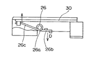
【0022】
ここで、牽引部20は、図12に示した従来技術とは異なり、カートリッジコンテナ22を付勢するコイルバネ状に形成された弾性部材26を図2に示したようにカートリッジコンテナ22の係合凹部22f近傍に設けている。このカートリッジコンテナ22には、係合凹部22fの近傍に挿入排出方向に延在する支持ピン22gと固定ピン22hとを形成している。そして、弾性部材26は、支持ピン22gに挿入して支持する螺旋状に巻かれたトーション部26aと、このトーション部26aから延在して固定ピン22hに固定される固定部26bと、駆動アーム部材30の係合凸部30bに当接させる付勢部26cとを一体に形成している。この弾性部材26は、駆動アーム部材30に対して支持ピン22gを支点として図2に示したトーション部26aの付勢による矢印A方向の付勢と、図2に示した矢印B点を支点とした弾性部材26によるベンドの付勢とを同時に加えている。従って、カートリッジコンテナ22は、この弾性部材26の付勢により挿入方向に付勢力が加えられて摺動するように形成されている。
【0023】
このように形成された本発明によるカートリッジ挿入排出装置をMD記録再生装置に採用した実施の形態を使用する場合、まず、図3に示したようにMDカートリジ1を牽引部20に挿入する。この際、駆動アーム部材30は、排出待機位置に停止しているカートリッジコンテナ22にMDカートリッジ1を挿入すると、カートリッジコンテナ22により係合凸部30bが押されて回転軸30aを中心にして回転する。これにより、駆動アーム部材30は、所定の開始検出スイッチ(図示せず)を押して自動的に回転を開始してMDカートリッジ1のローディング動作を実行する。
【0024】
そして、駆動アーム部材30が自動的に回転すると、図4に示すように、係合凸部30bが弾性部材26により付勢された状態でカートリッジコンテナ22をローディングシャシ24内に摺動させる。また、カートリッジコンテナ22をローディングシャシ24内に摺動すると、図5に示すように、MDカートリジ1が牽引部20の内部(図示されないターンテーブルの略上方)に収納される。この際、弾性部材26は、図2に示した矢印B点を支点とするベンドの付勢力により駆動アーム部材30をカートリッジコンテナ22の係合凹部22f片側に付勢することで摺動による衝撃を吸収している。
【0025】
また、弾性部材26は、図6に示すように、トーション部26aの付勢力により付勢部26cが駆動アーム部材30(図2に示した矢印A方向)に付勢を加える。これによりカートリッジコンテナ22は、付勢部26cの付勢力により固定部26b側を図6に示した矢印D方向に付勢する。そして、このように弾性部材26がカートリッジコンテナ22を付勢した状態で、図1に示した昇降部40の回転アーム42が回転して牽引部20を図7に示すように記録再生位置に降下させる。この際、牽引部20は、弾性部材26が駆動アーム部材30を付勢した状態で降下する。牽引部20が降下した後、図8に示すように弾性部材26が駆動アーム部材30を付勢した状態にあるため、安定した挿入排出動作を実行することができる。
このように、本発明によるカートリッジ挿入排出装置をMD記録再生装置に採用した実施の形態によると、弾性部材26がカートリッジコンテナ22を常に付勢しているため、従来技術のように摺動速度が加速されてチャッキング待機位置で衝撃が加えられることを防止することができる。
【0026】
また、このように弾性部材26が常にカートリッジコンテナ22を付勢することで、従来技術のように摺動して停止する際に加速により発生する衝撃音を吸収することが可能になる。
さらに、弾性部材26をカートリッジコンテナ22に装着してローディングシャシ24内に配置しているため、弾性部材26の変位によって本体10の上下方向の厚みを厚くする必要がなく大型化することを防止することができる。
ここで、本実施の形態では、コイルバネ形状に形成された弾性部材26によりカートリッジコンテナ22を付勢した実施の形態を説明したが、これに限定するものではなく、例えば、板バネによる弾性部材を使用して付勢してもよい。図9は、このように板バネからなる図2に示した弾性部材の他の実施の形態を示す斜視図である。また、図10は、図2に示した弾性部材の更なる他の実施の形態を示す斜視図である。
【0027】
図9に示すように、図2に示した弾性部材の他の実施の形態は、カートリッジコンテナ28の係合凹部28fにネジ穴28hを設け、このネジ穴28hにネジ2により締結される固定部27bと、この固定部27bから傾斜して延在する延在部27aと、この延在部27aから更に延在する付勢部27cとを一体に備え板バネ状に形成されている。ここで付勢部27cには、側面から上方向に垂直に延在し、この側面に直交する方向に弾性を備えた側壁27dを一体に形成している。このように形成された弾性部材27は、係合凹部28fにネジ2によりネジ止めされて付勢部27cと側壁27dとが駆動アーム部材30に当接するように形成されている。ここで、弾性部材27は、係合凹部28fにネジ2によりネジ止めすることに限定されるものではなく、例えば、カシメにより固定してもよい。
【0028】
また、このように形成された弾性部材27は、固定部27bを支点とする図9に示した矢印F方向への付勢と、側壁27dによる図9に示した矢印G方向への付勢とを各々駆動アーム部材30に加えている。これにより弾性部材27は、図3乃至図8に示したコイルバネ状の弾性部材と同様に動作し、常にカートリッジコンテナ(図示せず)を付勢する。
従って、このように形成された弾性部材の他の実施の形態によると、図2に示した弾性部材と同様の効果を得ることが出来るとともに、板バネ状に形成しているため、板厚および板面積を調節することで駆動アーム部材を付勢する付勢力を自由に調節することが可能になる。
【0029】
一方、このように係合凹部にネジ止めする弾性部材とは異なり、係合凹部に板バネ部を直接形成する弾性部材の更なる他の実施の形態がある。この弾性部材の更なる他の実施の形態は、図10に示すように、カートリッジコンテナ29の係合凹部29fに直接、駆動アーム部材30に当接して付勢する垂直付勢バネ29iと側部付勢バネ29jとを一体に形成している。これにより、駆動アーム部材30は、垂直付勢バネ29iにより図10に示した矢印I方向に付勢されるとともに、側部付勢バネ29jにより図10に示した矢印H方向に付勢される。
従って、このように形成された弾性部材の更なる他の実施の形態は、図9に示した弾性部材の他の実施の形態と同様の効果を得ることが出来るとともに、係合凹部29fに直接、垂直付勢バネ29iと側部付勢バネ29jとを形成することで部品点数を削減して製品全体のコストを低減することが可能になる。
【0030】
以上、本発明によるカートリッジ挿入排出装置の実施の形態を詳細に説明したが、本発明は前述した実施の形態に限定されるものではなく、その要旨を逸脱しない範囲で変更可能である。
例えば、本発明によるカートリッジ挿入排出装置をMD記録再生装置に採用した実施の形態を説明したが、これに限定されるものではなく、FD、MOなどの記憶媒体を記録再生する記録再生装置に採用することも可能である。
【0031】
【発明の効果】
このように本発明によるカートリッジ挿入排出装置によれば、弾性部材の付勢力において中立点が無くなるため、カートリッジ挿入方向の摺動停止時に発生する衝撃を防止でき、カートリッジの保持力を増加しなくても安定した動作が可能となる。
また、カートリッジを保持して排出方向および挿入方向のいずれかに弾性部材の付勢により加速して停止する際、本体内で発生する衝撃音を吸収することが可能になり、衝撃音を無くすことができる。
さらに、弾性部材を牽引部の内部に収納しているため、弾性部材の変位によって記録再生装置の本体内部を上下方向に厚く形成する必要がなく大型化することを防止することができる。
【図面の簡単な説明】
【図1】本発明によるカートリッジ挿入排出装置をMD記録再生装置に採用した実施の形態を示す斜視図。
【図2】図1に示した牽引部の詳細を示す斜視図。
【図3】図2に示したカートリッジ挿入排出装置にMDカートリッジを挿入する状態を示す図。
【図4】図3に示した駆動アーム部材の動作を示す動作説明図。
【図5】図3に示した駆動アーム部材の動作後の状態を示す図。
【図6】図5に示した矢印C方向から見た図。
【図7】図5に示したMDカートリッジを記録再生位置に移動した状態を示す図。
【図8】図7に示した矢印E方向から見た図。
【図9】図2に示した弾性部材の他の実施の形態を示す斜視図。
【図10】図2に示した弾性部材の更なる他の実施の形態を示す斜視図。
【図11】従来のカートリッジ挿入排出装置を示す斜視図。
【図12】図11に示した牽引部を示す斜視図。
【図13】図12に示したカートリッジコンテナの詳細を示す一部切り欠いた斜視図。
【図14】図11に示したMDカートリッジを記録再生位置に移動した状態を示す図。
【図15】図11に示した駆動アーム部材の動作を示す動作説明図。
【図16】図12に示した弾性部材の動作を示す動作説明図。
【符号の説明】
1 MDカートリッジ
1a、1b 牽引用溝部
10 本体
12 記録再生面
20 牽引部
22 カートリッジコンテナ
22a、22b、22c ガイドピン
22d、22e 保持部
22f 係合凹部
22g 支持ピン
22h 固定ピン
24 ローディングシャシ
24a、24b 軌道溝
30 駆動アーム部材
30a 回転軸
30b 係合凸部
40 昇降部
42 回転アーム
42a 回転軸
44 ロック部材
46 係合部[0001]
TECHNICAL FIELD OF THE INVENTION
The present invention relates to a cartridge insertion / ejection device, and more particularly, to a cartridge insertion / ejection device for inserting and ejecting a cartridge containing a storage medium into a main body of a recording / reproducing device.
[0002]
[Prior art]
2. Description of the Related Art Conventionally, a cartridge such as an MD, FD, or MO containing a storage medium records and reproduces predetermined information by inserting it into a main body of a recording and reproducing apparatus and moving it to a recording and reproducing position. In this case, a cartridge insertion / ejection device for inserting and ejecting a cartridge into and from a recording / reproduction position is provided in the main body of the recording / reproduction device.
[0003]
FIG. 11 is a perspective view showing a conventional cartridge insertion / ejection apparatus employed in the MD recording / reproducing apparatus. FIG. 12 is a perspective view showing the
[0004]
As shown in FIG. 11, a conventional cartridge insertion / ejection device employed in an MD recording / reproducing apparatus is provided in a
[0005]
Here, in the
In addition, the
[0006]
Further, as shown in FIG. 12, the pulling
[0007]
Further, the
[0008]
Referring to FIG. 11 again, in the conventional cartridge insertion / ejection device thus formed, when the
[0009]
When the
[0010]
At this time, the engagement convex
[0011]
When the
As described above, in the conventional cartridge insertion / ejection device, the
[0012]
[Problems to be solved by the invention]
However, in the conventional cartridge insertion / ejection device, when the
[0013]
Further, in the conventional cartridge insertion / ejection device, the neutral
[0014]
Further, in the conventional cartridge insertion / ejection device, as shown in FIG. 16B, particularly when the
SUMMARY OF THE INVENTION It is an object of the present invention to provide a cartridge inserting / ejecting device which solves such a problem, prevents an impact sound due to an impact of a sliding operation and a detachment of a cartridge, and can reliably position the cartridge at a recording / reproduction position.
[0015]
[Means for Solving the Problems]
In order to solve the above-mentioned problem, the present invention is to insert a cartridge containing a storage medium and Loading The main body and the cartridge inserted in the main body are formed so as to be slidable in the insertion / ejection direction while holding the cartridge. A cartridge container and a loading chassis that supports the cartridge container so as to be slidable in the insertion / ejection direction. Towing part and this Cartridge container Engage with Te A drive arm member that slides in the cartridge insertion / ejection direction and Loading chassis With the operation of the drive arm member Loading chassis Move up and down Loading And an elevating part for positioning at the position, A concave engagement recess is formed at the rear end of the cartridge container in the insertion direction to engage the drive arm member. Provided in When it comes into contact with the drive arm member, Is provided with an elastic member which always urges.
[0016]
Here, the elastic member is , Cartridge container Engagement recess To One end Energized by fixing the other end to the drive arm member Coil spring Is preferred. Also, the elastic member , Cartridge container Engagement recess To Oneness It is preferable that the formed leaf spring is biased by abutting the driving arm member.
[0017]
BEST MODE FOR CARRYING OUT THE INVENTION
Next, an embodiment of a cartridge insertion / ejection device according to the present invention will be described in detail with reference to the accompanying drawings. FIG. 1 is a perspective view showing an embodiment in which the cartridge insertion / ejection device according to the present invention is employed in an MD recording / reproducing device. FIG. 2 is a perspective view showing details of the
[0018]
As shown in FIG. 1, in the embodiment in which the cartridge insertion / ejection device according to the present invention is employed in an MD recording / reproducing apparatus, similarly to the prior art shown in FIG. A
[0019]
Here, in the
The lifting
[0020]
The
[0021]
As shown in FIG. 2, the
[0022]
Here, unlike the prior art shown in FIG. 12, the
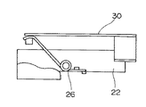
[0023]
When using the embodiment in which the cartridge insertion / ejection device according to the present invention thus formed is employed in an MD recording / reproducing device, first, the
[0024]
Then, when the
[0025]
As shown in FIG. 6, the
As described above, according to the embodiment in which the cartridge insertion / ejection device according to the present invention is employed in the MD recording / reproducing device, since the
[0026]
In addition, since the
Further, since the
Here, in the present embodiment, the embodiment in which the
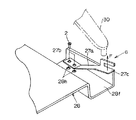
[0027]
As shown in FIG. 9, another embodiment of the elastic member shown in FIG. 27b, an extending portion 27a extending obliquely from the fixed
[0028]
Further, the elastic member 27 thus formed is urged in the direction of arrow F shown in FIG. 9 with the fixing
Therefore, according to another embodiment of the elastic member formed as described above, the same effect as the elastic member shown in FIG. 2 can be obtained, and since the elastic member is formed in a leaf spring shape, the plate thickness and By adjusting the plate area, the urging force for urging the drive arm member can be freely adjusted.
[0029]
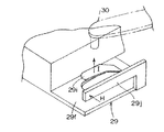
On the other hand, there is still another embodiment of an elastic member in which a leaf spring portion is directly formed in the engaging concave portion, unlike the elastic member screwed to the engaging concave portion. As shown in FIG. 10, a further embodiment of the elastic member includes a
Therefore, the other embodiment of the elastic member formed as described above can obtain the same effect as that of the other embodiment of the elastic member shown in FIG. By forming the
[0030]
As described above, the embodiment of the cartridge insertion / ejection device according to the present invention has been described in detail. However, the present invention is not limited to the above-described embodiment, and can be changed without departing from the gist thereof.
For example, an embodiment has been described in which the cartridge insertion / ejection device according to the present invention is applied to an MD recording / reproducing device. However, the present invention is not limited to this. It is also possible.
[0031]
【The invention's effect】
As described above, according to the cartridge insertion / ejection device of the present invention, since the neutral point is eliminated in the urging force of the elastic member, it is possible to prevent an impact generated when the slide stops in the cartridge insertion direction, without increasing the holding force of the cartridge. This also enables stable operation.
Further, when the cartridge is held and accelerated and stopped by the urging of the elastic member in either the ejection direction or the insertion direction, the impact sound generated in the main body can be absorbed, and the impact sound can be eliminated. Can be.
Further, since the elastic member is housed in the traction portion, it is not necessary to form the inside of the main body of the recording / reproducing apparatus vertically thick due to the displacement of the elastic member, and it is possible to prevent an increase in size.
[Brief description of the drawings]
FIG. 1 is a perspective view showing an embodiment in which a cartridge insertion / ejection device according to the present invention is employed in an MD recording / reproducing device.
FIG. 2 is a perspective view showing details of a traction unit shown in FIG. 1;
FIG. 3 is a diagram showing a state where an MD cartridge is inserted into the cartridge insertion / ejection device shown in FIG. 2;
FIG. 4 is an operation explanatory view showing an operation of the drive arm member shown in FIG. 3;
FIG. 5 is a view showing a state after the operation of the drive arm member shown in FIG. 3;
FIG. 6 is a view as seen from the direction of arrow C shown in FIG. 5;
FIG. 7 is a diagram showing a state in which the MD cartridge shown in FIG. 5 has been moved to a recording / reproducing position.
FIG. 8 is a view as seen from a direction of an arrow E shown in FIG. 7;
FIG. 9 is a perspective view showing another embodiment of the elastic member shown in FIG. 2;
FIG. 10 is a perspective view showing still another embodiment of the elastic member shown in FIG. 2;
FIG. 11 is a perspective view showing a conventional cartridge insertion / ejection device.
FIG. 12 is a perspective view showing the traction unit shown in FIG. 11;
FIG. 13 is a partially cutaway perspective view showing details of the cartridge container shown in FIG. 12;
FIG. 14 is a view showing a state where the MD cartridge shown in FIG. 11 has been moved to a recording / reproducing position.
FIG. 15 is an operation explanatory view showing an operation of the drive arm member shown in FIG. 11;
FIG. 16 is an operation explanatory view showing the operation of the elastic member shown in FIG. 12;
[Explanation of symbols]
1 MD cartridge
1a, 1b Tow groove
10 body
12 Recording / playback surface
20 Towing unit
22 Cartridge container
22a, 22b, 22c Guide pin
22d, 22e holding part
22f engagement recess
22g support pin
22h Fixed pin
24 Loading chassis
24a, 24b Track groove
30 Drive arm members
30a Rotary axis
30b engaging projection
40 lifting section
42 rotating arm
42a Rotary axis
44 Lock member
46 Engagement part
Claims (3)
前記本体内に挿入した前記カートリッジを保持して挿入排出方向に摺動可能に形成されたカートリッジコンテナ及びこのカートリッジコンテナを挿入排出方向に摺動可能に支持するローディングシャシを備えた牽引部と、
前記カートリッジコンテナに係合して前記カートリッジの挿入排出方向に摺動させる駆動アーム部材と、
前記本体内で前記ローディングシャシと係合して前記駆動アーム部材の動作に合わせて前記ローディングシャシを上下動させてローディング位置に位置決めする昇降部とを備え、
前記カートリッジコンテナの挿入方向後端に凹状の係合凹部を形成して前記駆動アーム部材を係合させるとともに、この係合凹部に設けられて前記駆動アーム部材に当接して上方向と排出方向とに常に付勢する弾性部材を設けたことを特徴とするカートリッジ挿入排出装置。 A main body into which a cartridge containing a storage medium is inserted and loaded ;
A traction unit having a cartridge container formed to be slidable in the insertion / ejection direction while holding the cartridge inserted in the main body, and a loading chassis for supporting the cartridge container slidably in the insertion / ejection direction ;
A drive arm member to slide in the insertion and ejection direction before Symbol cartridge engaged with the cartridge container,
An elevating unit that engages with the loading chassis in the main body and moves the loading chassis up and down in accordance with the operation of the drive arm member to position the loading chassis at a loading position;
A concave engagement recess is formed at the rear end of the cartridge container in the insertion direction to engage the drive arm member. The drive arm member is provided in the engagement recess and contacts the drive arm member to move upward and to the discharge direction. A cartridge inserting / ejecting device, characterized in that an elastic member that constantly urges the cartridge is provided.
前記弾性部材は、前記カートリッジコンテナの係合凹部に一端を固定して他端を前記駆動アーム部材に当接させることで付勢するコイルバネであることを特徴とするカートリッジ挿入排出装置。The cartridge insertion / ejection device according to claim 1,
The cartridge insertion / ejection device , wherein the elastic member is a coil spring that is biased by fixing one end to an engagement recess of the cartridge container and bringing the other end into contact with the drive arm member.
前記弾性部材は、前記カートリッジコンテナの係合凹部に一体形成した板バネを前記駆動アーム部材に当接させることで付勢していることを特徴とするカートリッジ挿入排出装置。The cartridge insertion / ejection device according to claim 1,
The cartridge insertion / ejection device , wherein the elastic member is urged by bringing a leaf spring integrally formed in an engagement concave portion of the cartridge container into contact with the drive arm member.
Priority Applications (1)
| Application Number | Priority Date | Filing Date | Title |
|---|---|---|---|
| JP25791799A JP3585102B2 (en) | 1999-09-10 | 1999-09-10 | Cartridge insertion / ejection device |
Applications Claiming Priority (1)
| Application Number | Priority Date | Filing Date | Title |
|---|---|---|---|
| JP25791799A JP3585102B2 (en) | 1999-09-10 | 1999-09-10 | Cartridge insertion / ejection device |
Publications (2)
| Publication Number | Publication Date |
|---|---|
| JP2001084676A JP2001084676A (en) | 2001-03-30 |
| JP3585102B2 true JP3585102B2 (en) | 2004-11-04 |
Family
ID=17312997
Family Applications (1)
| Application Number | Title | Priority Date | Filing Date |
|---|---|---|---|
| JP25791799A Expired - Fee Related JP3585102B2 (en) | 1999-09-10 | 1999-09-10 | Cartridge insertion / ejection device |
Country Status (1)
| Country | Link |
|---|---|
| JP (1) | JP3585102B2 (en) |
-
1999
- 1999-09-10 JP JP25791799A patent/JP3585102B2/en not_active Expired - Fee Related
Also Published As
| Publication number | Publication date |
|---|---|
| JP2001084676A (en) | 2001-03-30 |
Similar Documents
| Publication | Publication Date | Title |
|---|---|---|
| US5878013A (en) | Recording and reproducing apparatus | |
| JP2882989B2 (en) | Optical disk recording and playback device | |
| JP3523120B2 (en) | Magneto-optical recording / reproducing device | |
| JPH10208359A (en) | Electronic apparatus | |
| US5586092A (en) | Magnetooptic disk player | |
| KR100437111B1 (en) | Optical disk roading apparatus for optical disk drive | |
| JP3585102B2 (en) | Cartridge insertion / ejection device | |
| KR20090113034A (en) | Optical disk apparatus | |
| US20070050792A1 (en) | Optical recording and playback apparatus to open and close a safety door | |
| JP2831608B2 (en) | Mini disc player | |
| JPH07192370A (en) | Cartridge insertion / drawing-out device of magneto-optical disk player | |
| JPH07334903A (en) | Disk player | |
| WO2000002201A1 (en) | Disk drive | |
| JP3791242B2 (en) | Recording medium mounting device | |
| JP3728979B2 (en) | Recording medium mounting device | |
| WO2007077678A1 (en) | Slot-in type disk device | |
| KR0155772B1 (en) | Mini disk player | |
| JP2000021067A (en) | Disk device | |
| JPH04372765A (en) | Shutter opening and closing mechanism of disk cartridge | |
| JP3596803B2 (en) | Information recording medium drive | |
| JP2672706B2 (en) | Loading device | |
| JP2990931B2 (en) | Cassette loading device | |
| JPS61296561A (en) | Disc driving device | |
| JP2001332000A (en) | Recording and/or reproducing device | |
| JPH09306130A (en) | Magnetic recording and reproducing device |
Legal Events
| Date | Code | Title | Description |
|---|---|---|---|
| A131 | Notification of reasons for refusal |
Free format text: JAPANESE INTERMEDIATE CODE: A131 Effective date: 20040330 |
|
| A521 | Written amendment |
Free format text: JAPANESE INTERMEDIATE CODE: A523 Effective date: 20040518 |
|
| TRDD | Decision of grant or rejection written | ||
| A01 | Written decision to grant a patent or to grant a registration (utility model) |
Free format text: JAPANESE INTERMEDIATE CODE: A01 Effective date: 20040629 |
|
| A61 | First payment of annual fees (during grant procedure) |
Free format text: JAPANESE INTERMEDIATE CODE: A61 Effective date: 20040729 |
|
| R150 | Certificate of patent or registration of utility model |
Free format text: JAPANESE INTERMEDIATE CODE: R150 |
|
| FPAY | Renewal fee payment (event date is renewal date of database) |
Free format text: PAYMENT UNTIL: 20070813 Year of fee payment: 3 |
|
| FPAY | Renewal fee payment (event date is renewal date of database) |
Free format text: PAYMENT UNTIL: 20080813 Year of fee payment: 4 |
|
| FPAY | Renewal fee payment (event date is renewal date of database) |
Free format text: PAYMENT UNTIL: 20080813 Year of fee payment: 4 |
|
| FPAY | Renewal fee payment (event date is renewal date of database) |
Free format text: PAYMENT UNTIL: 20090813 Year of fee payment: 5 |
|
| FPAY | Renewal fee payment (event date is renewal date of database) |
Free format text: PAYMENT UNTIL: 20100813 Year of fee payment: 6 |
|
| LAPS | Cancellation because of no payment of annual fees |