JP3583353B2 - Communication terminal device and base station device - Google Patents
Communication terminal device and base station device Download PDFInfo
- Publication number
- JP3583353B2 JP3583353B2 JP2000201665A JP2000201665A JP3583353B2 JP 3583353 B2 JP3583353 B2 JP 3583353B2 JP 2000201665 A JP2000201665 A JP 2000201665A JP 2000201665 A JP2000201665 A JP 2000201665A JP 3583353 B2 JP3583353 B2 JP 3583353B2
- Authority
- JP
- Japan
- Prior art keywords
- signal
- base station
- communication terminal
- reception quality
- channel signal
- Prior art date
- Legal status (The legal status is an assumption and is not a legal conclusion. Google has not performed a legal analysis and makes no representation as to the accuracy of the status listed.)
- Expired - Fee Related
Links
Images


Classifications
-
- H—ELECTRICITY
- H04—ELECTRIC COMMUNICATION TECHNIQUE
- H04B—TRANSMISSION
- H04B7/00—Radio transmission systems, i.e. using radiation field
- H04B7/14—Relay systems
- H04B7/15—Active relay systems
- H04B7/155—Ground-based stations
-
- H—ELECTRICITY
- H04—ELECTRIC COMMUNICATION TECHNIQUE
- H04L—TRANSMISSION OF DIGITAL INFORMATION, e.g. TELEGRAPHIC COMMUNICATION
- H04L1/00—Arrangements for detecting or preventing errors in the information received
- H04L1/20—Arrangements for detecting or preventing errors in the information received using signal quality detector
-
- H—ELECTRICITY
- H04—ELECTRIC COMMUNICATION TECHNIQUE
- H04L—TRANSMISSION OF DIGITAL INFORMATION, e.g. TELEGRAPHIC COMMUNICATION
- H04L1/00—Arrangements for detecting or preventing errors in the information received
- H04L1/0001—Systems modifying transmission characteristics according to link quality, e.g. power backoff
- H04L1/0002—Systems modifying transmission characteristics according to link quality, e.g. power backoff by adapting the transmission rate
- H04L1/0003—Systems modifying transmission characteristics according to link quality, e.g. power backoff by adapting the transmission rate by switching between different modulation schemes
-
- H—ELECTRICITY
- H04—ELECTRIC COMMUNICATION TECHNIQUE
- H04L—TRANSMISSION OF DIGITAL INFORMATION, e.g. TELEGRAPHIC COMMUNICATION
- H04L1/00—Arrangements for detecting or preventing errors in the information received
- H04L1/0001—Systems modifying transmission characteristics according to link quality, e.g. power backoff
- H04L1/0009—Systems modifying transmission characteristics according to link quality, e.g. power backoff by adapting the channel coding
-
- H—ELECTRICITY
- H04—ELECTRIC COMMUNICATION TECHNIQUE
- H04W—WIRELESS COMMUNICATION NETWORKS
- H04W24/00—Supervisory, monitoring or testing arrangements
-
- H—ELECTRICITY
- H04—ELECTRIC COMMUNICATION TECHNIQUE
- H04W—WIRELESS COMMUNICATION NETWORKS
- H04W88/00—Devices specially adapted for wireless communication networks, e.g. terminals, base stations or access point devices
- H04W88/02—Terminal devices
-
- H—ELECTRICITY
- H04—ELECTRIC COMMUNICATION TECHNIQUE
- H04W—WIRELESS COMMUNICATION NETWORKS
- H04W88/00—Devices specially adapted for wireless communication networks, e.g. terminals, base stations or access point devices
- H04W88/08—Access point devices
Landscapes
- Engineering & Computer Science (AREA)
- Computer Networks & Wireless Communication (AREA)
- Signal Processing (AREA)
- Quality & Reliability (AREA)
- Mobile Radio Communication Systems (AREA)
- Digital Transmission Methods That Use Modulated Carrier Waves (AREA)
Description
【0001】
【発明の属する技術分野】
本発明は、ディジタル移動体通信システムに用いられる通信装置に関し、特に、W−CDMA(Wide band−Code Division Multiple Access)方式のディジタル移動体通信システムに用いられる基地局装置および通信端末装置に関する。
【0002】
【従来の技術】
近年、W−CDMA方式のディジタル移動体通信システムにおいては、下り回線を用いた高速データ通信(下り高速パケット通信)が提案されている。以下、下り回線を用いた高速データ通信について、図18を参照して説明する。図18は、下り回線を用いた高速データ通信が行われるシステムの様子を示す模式図である。
【0003】
図18において、通信端末装置13は、基地局装置11がカバーするエリアと基地局装置12がカバーするエリアに存在しているものとする。まず、基地局装置11は、自局がカバーするエリアに存在する通信端末装置に対して、共通制御チャネル(CPICH:Common PIlot CHannel)を用いて共通既知信号を送信する。同様に、基地局装置12は、自局がカバーするエリアに存在する通信端末装置に対して、CPICHを用いて共通既知信号を送信する。
【0004】
以下、説明の簡略化のために、CPICHを用いて通信される信号を「CPICH信号」とする。同様に、ダウンリンクシェアードチャネル(DSCH:Downlink Shared CHannel)を用いて通信される信号を「DSCH信号」とし、個別物理チャネル(DPCH:Dedicated Physical CHannel)を用いて通信される信号を「DPCH信号」とする。
【0005】
通信端末装置13は、基地局装置11により送信されたCPICH信号および基地局装置12により送信されたCPICH信号の受信品質を測定する。次に、通信端末装置13は、DSCH信号の要求先として、基地局装置11および基地局装置12のうち、良好な品質で受信できたCPICH信号を送信した基地局装置(ここでは基地局装置11とする。)を選択する。
【0006】
この後、通信端末装置13は、基地局装置11により送信されたCPICH信号の受信品質に基づいて、通信端末装置13におけるDSCH信号の受信品質が所要品質を実現するように、DSCH信号に用いことが可能な変調方式および誤り訂正符号化方式を決定する。通信端末装置13は、このように決定した変調方式および誤り訂正符号化方式を通知するための情報と、DSCH信号の要求先として基地局装置11を通知するための情報と、を含むDPCH信号を送信する。
【0007】
なお、通信端末装置13だけでなく、基地局装置11がカバーするエリアおよび基地局装置12がカバーするエリアに存在する他の通信端末装置も、上述したような手順に従って、DPCH信号を送信する。
【0008】
基地局装置11および基地局装置12は、通信端末装置13を含む通信端末装置により送信されたDPCH信号を受信し、自局に対してDSCH信号を要求している通信端末装置を認識する。さらに、基地局装置12および基地局装置12は、自局にDSCH信号の送信を要求している通信端末装置のうち、通知された変調方式および誤り訂正符号化方式に基づいて、下り回線(すなわちDSCH)の状況が良く、かつ、下り回線のサービス要求が良い(遅延時間が短い)通信端末装置を選択する。
【0009】
この後、基地局装置11および基地局装置12は、選択した通信端末装置に対して、この通信端末装置により通知された変調方式および誤り訂正符号化方式を用いてDSCH信号を送信する。
【0010】
このようにして、基地局装置11および基地局装置12は、下り回線の状況が良く、かつ、下り回線のサービス要求が良い通信端末装置に対して、高速データ通信を行うことができる。
【0011】
なお、通信端末装置13は、1つの基地局装置(一例として基地局装置11とする。)がカバーするエリアのみに存在している場合には、基地局装置11により送信されたCPICH信号の受信品質に基づいて、DSCH信号に用いることが可能な変調方式および誤り訂正符号化方式を決定する。この後、通信端末装置13は、決定した変調方式および誤り訂正符号化方式を通知するための情報を含むDPCH信号を送信する。以後、基地局装置11においては、上述したようなものと同様の処理が行われる。
【0012】
【発明が解決しようとする課題】
しかしながら、上記従来の下り回線を用いた高速データ通信においては、実際には、基地局装置におけるDSCH信号の送信電力とCPICH信号の送信電力とが、基地局装置毎に異なるので、以下に示すような問題がある。
【0013】
まず、第1に、通信端末装置は、CPICH信号の受信品質に基づいて、DSCH信号に用いることが可能な変調方式および誤り訂正符号化方式を決定しているが、基地局装置におけるDSCH信号の送信電力がCPICH信号の送信電力より小さい場合には、DSCH信号の受信品質が所要品質を満たすための変調方式および誤り訂正符号化方式よりも高速な方式を選択することになる。このため、通信端末装置におけるDSCH信号の受信品質が所要品質を下回る可能性がある。
【0014】
具体例として、基地局装置におけるDSCH信号の送信電力がCPICH信号の送信電力よりも小さいために、図19に示すように、通信端末装置におけるCPICH信号の受信品質が25[dB]となり、通信端末装置におけるDSCH信号の受信品質が20[dB]となった場合について説明する。
【0015】
この場合、通信端末装置は、CPICH信号の受信品質に基づいて、DSCH信号の受信品質が所要品質を満たすように、DSCH信号に用いる変調方式としてQPSK変調方式を選択する。ところが、実際のDSCHの受信品質は、CPICH信号よりも5[dB]だけ低いので、QPSK変調が用いられたDSCH信号の受信品質は、所要品質を下回ることになる。通信端末装置が、所要品質を満たすDSCH信号を受信するためには、BPSK変調が用いられたDSCH信号を受信する必要がある。
【0016】
逆に、通信端末装置は、基地局装置におけるDSCH信号の送信電力がCPICH信号の送信電力より大きい場合には、DSCH信号の受信品質が所要品質を満たすための変調方式および誤り訂正符号化方式よりも低速な方式を選択することになる。このため、通信端末装置は、本来、より高速なデータ通信が可能となるような変調方式および誤り訂正符号化方式によるDSCH信号を受信することができるのにもかかわらず、実際には、推定されたCPICH信号の受信品質に基づいて決定された変調方式および誤り訂正符号化方式によるDSCH信号を受信することになる。
【0017】
具体例として、図19において、通信端末装置におけるCPICH信号の受信品質が20[dB]となり、通信端末装置におけるDSCH信号の受信品質が25[dB]となった場合について説明する。
【0018】
この場合、この場合、通信端末装置は、CPICH信号の受信品質に基づいて、DSCH信号の受信品質が所要品質を満たすように、DSCH信号に用いる変調方式としてBPSK変調方式を選択する。ところが、実際のDSCHの受信品質は、CPICH信号よりも5[dB]だけ高いので、通信端末装置は、BPSK変調よりも高速なQPSK変調が用いられたDSCH信号を受信しても、その所要品質を満たすことができる。
【0019】
第2に、通信端末装置が、複数の基地局装置がカバーするエリアに存在する場合には、通信端末装置における受信品質が高いCPICH信号を送信した基地局装置を、DSCH信号の要求先として選択するので、上記複数の基地局装置におけるDSCH信号の送信電力とCPICH信号の送信電力の大きさによっては、最良の品質で受信できるDSCH信号を送信する基地局装置を正確に選択することが不可能となる。
【0020】
具体的には、図18において、基地局装置11におけるDSCH信号の送信電力とCPICH信号の送信電力が同じであり、基地局装置12におけるDSCH信号の送信電力がCPICH信号の送信電力より10[dB]だけ低いものとし、さらに、通信端末装置13においては、基地局装置11から送信されたCPICH信号の受信品質が8[dB]となり、基地局装置12により送信されたCPICH信号の受信品質が12[dB]となったとする。
【0021】
この場合、従来方式では、CPICH信号の受信品質の良い基地局装置12をDSCH信号の要求先として選択してしまう。しかしながら、実際には、基地局装置11からDSCH信号を送信した場合の受信品質は8[dB]となるのに対して、基地局装置12からDSCH信号を送信した場合の受信品質は2[dB]となってしまう。よって、本来品質のよい基地局装置11から受信していれば得られた8[dB]の品質に対して6[dB]も低い2[dB]の品質しか得られなくなってしまう。
【0022】
以上のように、上記従来の下り回線を用いた高速データ通信においては、通信端末装置は、基地局装置により送信されるDSCH信号の受信品質を正確に推定することができないので、通信端末装置は、最良の品質でDSCH信号を受信することができない(基地局装置は、通信端末装置により最良の品質で受信されるDSCH信号を通信端末装置に対して送信できない)という問題がある。
【0023】
本発明は、かかる点に鑑みてなされたものであり、最良の品質でDSCH信号を受信できる通信端末装置、または、通信端末装置に最良の品質で受信されるDSCH信号を送信できる基地局装置を提供することを目的とする。
【0024】
【課題を解決するための手段】
本発明の通信端末装置は、基地局装置により送信された制御チャネル信号の受信品質を測定する測定手段と、前記基地局装置により決定された変調方式および符号化方式にて前記基地局装置により送信されたデータチャネル信号を受信するとともに前記基地局装置における制御チャネル信号の送信電力値の情報およびデータチャネル信号の送信電力値の情報を受信する受信手段と、前記測定手段により測定された制御チャネル信号の受信品質と前記受信手段にて受信した制御チャネル信号の前記送信電力値の情報およびデータチャネル信号の前記送信電力値の情報とに基づいて、前記基地局装置により送信される前記データチャネル信号の受信品質を推定する推定手段と、を具備する構成を採る。
【0025】
この構成によれば、基地局装置は、通信端末装置におけるデータチャネル信号の受信品質を正確に認識することができるので、データチャネル信号の受信品質が所要品質を満たし、かつ、最良のデータチャネル信号(最適な変調・符号化方式が用いられたデータチャネル信号)を受信することができるように、データチャネル信号に用いることが可能な変調・符号化方式を正確に決定することができる。
【0026】
本発明の通信端末装置は、前記推定手段において推定されたデータチャネルの受信品質に基づいて、前記変調方式および前記符号化方式を決定する決定手段を具備する構成を採る。
【0027】
この構成によれば、通信端末装置は、データチャネル信号の受信品質を正確に認識することができるので、データチャネル信号の受信品質が所要品質を満たし、かつ、最良のデータチャネル信号(最適な変調・符号化方式が用いられたデータチャネル信号)を受信することができるように、データチャネル信号に用いることが可能な変調・符号化方式を正確に決定することができる。
本発明の通信端末装置は、前記推定手段は、制御チャネル信号の送信電力値とデータチャネルの送信電力値の比を、測定した制御チャネル信号の受信品質に反映した値を推定したデータチャネルの受信品質とする構成を採る。
この構成によれば、データチャネル信号の受信品質を正確に認識することができるので、データチャネル信号の受信品質が所要品質を満たし、かつ、最良のデータチャネル信号(最適な変調・符号化方式が用いられたデータチャネル信号)を受信することができるように、データチャネル信号に用いることが可能な変調・符号化方式を正確に決定することができる。
【0028】
本発明の通信端末装置は、データチャネル信号の要求先として、すべての基地局装置のうち推定されたデータチャネル信号の受信品質が良好である対象基地局装置を選択する選択手段を具備し、前記受信手段は、前記推定手段により推定された前記対象基地局装置に対応するデータチャネル信号の受信品質に基づいて決定された変調方式および符号化方式が前記対象基地局装置により用いられたデータチャネル信号を受信する構成を採る。
【0029】
この構成によれば、通信端末装置は、各基地局装置により送信されるデータチャネル信号の受信品質を正確に推定することができるので、データチャネル信号の要求先として、最良の品質で受信できるデータチャネル信号を送信する基地局装置を正確に選択することができる。さらに、基地局装置は、通信端末装置に送信するデータチャネル信号に用いることが可能な変調・符号化方式を正確に決定することができる。
【0030】
本発明の通信端末装置は、前記受信手段において受信した信号からデータチャネルの信号を取り出す第1逆拡散手段と、前記受信手段において受信した信号から前記基地局装置における制御チャネル信号およびデータチャネル信号の送信電力値の情報を取り出す第2逆拡散手段と、を具備し、前記推定手段は、測定手段により測定された制御チャネル信号の受信品質と、前記第2拡散手段において取り出された制御チャネル信号およびデータチャネル信号の送信電力値の情報に基づいて、データチャネルの受信品質を推定する構成を採る。
【0031】
この構成によれば、符号多重化されたデータチャネルの信号と、基地局装置における制御チャネル信号およびデータチャネル信号の送信電力値の情報と、を分離することができ、データチャネル信号の受信品質を正確に認識することができるので、データチャネル信号の受信品質が所要品質を満たし、かつ、最良のデータチャネル信号(最適な変調・符号化方式が用いられたデータチャネル信号)を受信することができるように、データチャネル信号に用いることが可能な変調・符号化方式を正確に決定することができる。
【0032】
本発明の基地局装置は、上記いずれかに記載の通信端末装置と無線通信を行う構成を採る。
【0033】
この構成によれば、良好な通信を行う基地局装置を提供することができる。
【0034】
本発明の通信方法は、通信相手により送信された制御チャネル信号の受信品質を測定する測定工程と、前記通信相手により決定された変調方式および符号化方式にて前記通信相手により送信されたデータチャネル信号を受信するとともに前記通信相手における制御チャネル信号の送信電力値の情報およびデータチャネル信号の送信電力値の情報を受信する受信工程と、前記測定工程により測定された制御チャネル信号の受信品質と前記受信工程にて受信した制御チャネル信号の前記送信電力値の情報およびデータチャネル信号の前記送信電力値の情報とに基づいて、前記通信相手により送信される前記データチャネル信号の受信品質を推定する推定工程と、を具備するようにした。
【0035】
この方法によれば、基地局装置は、通信端末装置におけるデータチャネル信号の受信品質を正確に認識することができるので、データチャネル信号の受信品質が所要品質を満たし、かつ、最良のデータチャネル信号(最適な変調・符号化方式が用いられたデータチャネル信号)を受信することができるように、データチャネル信号に用いることが可能な変調・符号化方式を正確に決定することができる。
【0036】
本発明の通信方法は、前記推定工程において推定されたデータチャネルの受信品質に基づいて、前記変調方式および前記符号化方式を決定する決定工程を具備するようにした。
【0037】
この方法によれば、通信端末装置は、各基地局装置により送信されるデータチャネル信号の受信品質を正確に推定することができるので、データチャネル信号の要求先として、最良の品質で受信できるデータチャネル信号を送信する基地局装置を正確に選択することができる。さらに、基地局装置は、通信端末装置に送信するデータチャネル信号に用いることが可能な変調・符号化方式を正確に決定することができる。
本発明の通信方法は、前記推定工程は、制御チャネル信号の送信電力値とデータチャネルの送信電力値の比を、測定した制御チャネル信号の受信品質に反映した値を推定したデータチャネルの受信品質とするようにした。
この方法によれば、データチャネル信号の受信品質を正確に認識することができるので、データチャネル信号の受信品質が所要品質を満たし、かつ、最良のデータチャネル信号(最適な変調・符号化方式が用いられたデータチャネル信号)を受信することができるように、データチャネル信号に用いることが可能な変調・符号化方式を正確に決定することができる。
本発明の通信方法は、データチャネル信号の要求先として、すべての基地局装置のうち推定されたデータチャネル信号の受信品質が良好である対象基地局装置を選択する選択工程を具備し、前記受信工程は、前記推定工程により推定された前記対象基地局装置に対応するデータチャネル信号の受信品質に基づいて決定された変調方式および符号化方式が前記対象基地局装置により用いられたデータチャネル信号を受信するようにした。
この方法によれば、各基地局装置により送信されるデータチャネル信号の受信品質を正確に推定することができるので、データチャネル信号の要求先として、最良の品質で受信できるデータチャネル信号を送信する基地局装置を正確に選択することができる。さらに、基地局装置は、通信端末装置に送信するデータチャネル信号に用いることが可能な変調・符号化方式を正確に決定することができる。
【0038】
【発明の実施の形態】
本発明の骨子は、基地局装置により送信された制御チャネル信号の通信端末装置における受信品質と、上記基地局装置における制御チャネル信号およびデータチャネル信号の送信電力値に基づいて、データチャネル信号に用いる変調方式および符号化方式を決定することである。また、本発明の骨子は、基地局装置により送信された制御チャネル信号の通信端末装置における受信品質と、上記基地局装置における制御チャネル信号およびデータチャネル信号の送信電力値に基づいて、すべての基地局装置の中からデータチャネル信号の要求先となる基地局装置を選択することである。
【0039】
以下、本発明の実施の形態について、図面を参照して詳細に説明する。実施の形態1および実施の形態2では、通信端末装置が、1つの基地局装置がカバーするエリアのみに存在する場合について説明し、実施の形態3および実施の形態4では、通信端末装置が、複数の基地局装置がカバーするエリアに存在する場合について説明する。
【0040】
(実施の形態1)
本実施の形態では、通信端末装置が、変調・符号化方式を決定する場合について説明する。まず、本実施の形態の概要について図1を参照して説明する。図1は、本発明の実施の形態1にかかる基地局装置および通信端末装置による無線通信の様子の一例を示す模式図である。図1において、通信端末装置102は、基地局装置101がカバーするエリアに存在し、基地局装置101と無線通信を行う。なお、図示されていないが、通信端末装置102以外の通信端末装置も、基地局装置101がカバーするエリアに存在し、基地局装置101と無線通信を行う。
【0041】
まず、基地局装置101は、通信端末装置に対して、CPICHを用いて共通既知信号を送信する。また、基地局装置101は、BCH(Broadcast Channel)を用いて、自局のCPICH信号の送信電力とDSCH信号の送信電力を示す情報(以下単に「送信電力情報」という。)および既知信号を含む信号を通信端末装置に対して送信する。なお、BCHを用いて通信される信号を「BCH信号」とする。
【0042】
ここで、CPICHは、基地局装置が各通信端末装置に対して共通既知信号を送信するためのチャネルである。DSCHは、基地局装置が、高伝送レートのパケット等のデータを所定の通信端末装置に対して送信するためのチャネルである。上りのDPCHは、各通信端末装置が、基地局装置に対して既知信号および音声データ等を含む信号を送信するチャネルであり、下りのDPCHは、基地局装置が、各通信端末装置に対して、既知信号、DSCHの送信先となる通信端末装置を示す情報や音声データ等を含む信号を送信するチャネルである。
【0043】
通信端末装置102は、基地局装置101により送信されたCPICH信号の受信品質、および、基地局装置101により送信されたBCH信号に含まれた送信電力情報を用いて、基地局装置101により送信されるDSCH信号の受信品質を推定する。さらに、通信端末装置102は、推定されたDSCH信号の受信品質に基づいて、このDSCH信号に用いることが可能な変調方式および誤り訂正符号化方式(以下単に「変調・符号化方式」という。)を決定し、基地局装置101に対して、決定した変調・符号化方式を通知するための情報(以下「MCS1」という。)を含むDPCH信号を送信する。
【0044】
基地局装置101は、通信端末装置102を含む通信端末装置により送信されたDPCH信号に含まれたMCS1に基づいて、すべての通信端末装置のうち、下り回線(すなわちDSCH)の状況が良く、かつ、下り回線のサービス要求が良い(遅延時間が短い)通信端末装置を選択する。この後、基地局装置101は、選択した通信端末装置に対して、この通信端末装置により通知された変調・符号化方式を用いてDSCH信号を送信する。以上が、本実施の形態の概要である。
【0045】
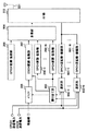
次いで、上記のような基地局装置および通信端末装置の構成について説明する。まず、本実施の形態にかかる基地局装置の構成について、図2を参照して説明する。図2は、本発明の実施の形態1にかかる基地局装置の構成を示すブロック図である。
【0046】
図2において、RF部202は、アンテナ201により受信された信号(受信信号)に対して、周波数変換等の所定の受信処理を行う。また、RF部202は、後述する多重部210からの多重信号に対して周波数変換等の所定の送信処理を行い、送信処理された多重信号をアンテナ201を介して送信する。
【0047】
DPCH逆拡散・復調部203−1〜203−Nは、RF部202により所定の受信処理がなされた受信信号に対して、それぞれ、通信端末装置1〜通信端末装置NのDPCHに割り当てられた拡散符号を用いて逆拡散処理を行う。さらに、DPCH逆拡散・復調部203−1〜203−Nは、逆拡散処理により得られた信号に対して復調処理を行うことにより復調信号を生成し、生成された復調信号からMCS1を抽出して割り当て部204に出力する。
【0048】
割り当て部204は、DPCH逆拡散・復調部203−1〜203−NからのMCS1を用いて、通信端末装置1〜Nのうち最も高速にDSCH信号を送信できる通信端末装置を選択する。さらに、割り当て部204は、選択した通信端末装置をバッファ205およびDPCH変調・拡散部206−1〜206−Nに報知し、選択した通信端末装置およびこの通信端末装置により通知された変調・符号化方式を、DSCH変調・拡散部207に報知する。
【0049】
バッファ205は、有線網を介して各通信端末装置に対する送信データを保持し、保持した送信データのうち割り当て部204により報知された通信端末装置の送信データをDSCH変調・拡散部207に出力する。DSCH変調・拡散部207は、バッファ205からの送信データに対して、割り当て部204により報知された変調・符号化方式に対応する誤り訂正符号化処理、変調処理および拡散処理を行い、割り当て部204により報知された通信端末装置のDSCH信号を生成する。
【0050】
DPCH変調・拡散部206−1〜206−Nは、それぞれ、通信端末装置1〜Nの送信データ、割り当て部204により報知された通信端末装置をDSCH信号の送信先とする旨を示す情報(以下「MCS2」という。)、および、既知信号を含む信号に対して、変調処理を行う。さらに、DPCH変調・拡散部206−1〜206−Nは、変調された信号に対して、それぞれ、通信端末装置1〜NのDPCHに割り当てられた拡散符号を用いて逆拡散処理を行うことにより、通信端末装置1〜NのDPCH信号を生成する。
【0051】
BCH変調・拡散部208は、CPICH信号の送信電力およびDSCH信号の送信電力を用いて送信電力情報を生成し、この送信電力情報および既知信号を含む信号に対して変調処理を行う。さらに、BCH変調・拡散部208は、変調処理された信号に対して、BCHに割り当てられた拡散符号を用いて拡散処理を行うことにより、BCH信号を生成する。
【0052】
CPICH変調・拡散部209は、既知信号を含む信号に対して変調処理を行う。さらに、CPICH変調・拡散部209は、変調処理された信号に対してCPICHに割り当てられた拡散符号を用いて拡散処理を行うことにより、CPICH信号を生成する。
【0053】
多重部210は、DPCH変調・拡散部206−1〜206−Nのそれぞれにより生成された通信端末装置1〜NのDPCH信号、DSCH変調・拡散部207により生成されたDSCH信号、BCH変調・拡散部208により生成されたBCH信号、および、CPICH変調・拡散部209により生成されたCPICH信号を多重することにより、多重信号を生成する。多重部210は、生成した多重信号を上述したRF部202に出力する。
【0054】
次に、本実施の形態にかかる通信端末装置の構成について、図3を参照して説明する。図3は、本発明の実施の形態1にかかる通信端末装置の構成を示すブロック図である。
【0055】
図3において、RF部302は、アンテナ301により受信された信号(受信信号)に対して、周波数変換等の所定の受信処理を行う。また、RF部302は、後述するDPCH変調・拡散部310からのDPCH信号に対して、周波数変換等の所定の送信処理を行い、送信処理がなされたDPCH信号をアンテナ301を介して送信する。
【0056】
CPICH逆拡散部303は、RF部302により受信処理された受信信号に対して、CPICHに割り当てられた拡散符号を用いて逆拡散処理を行う。測定部304は、CPICH逆拡散部303により逆拡散処理された信号(すなわちCPICH信号)の受信品質(例えばSIR等)を測定し、測定されたCPICH信号の受信品質をSIR推定部305に出力する。
【0057】
BCH逆拡散部306は、RF部302により受信処理された受信信号に対して、BCHに割り当てられた拡散符号を用いて逆拡散処理を行う。BCH復調部307は、BCH逆拡散部306により逆拡散処理された受信信号に対して復調処理を行うことにより、復調信号を生成する。また、BCH復調部307は、生成された復調信号から送信電力情報を抽出し、抽出した送信電力情報をSIR推定部305に出力する。
【0058】
SIR推定部305は、測定部304からのCPICH信号の受信品質、および、BCH復調部307からの送信電力情報を用いて、DSCH信号の受信品質を推定する。
【0059】
MCS1決定部308は、推定されたDSCH信号の受信品質に基づいて、DSCH信号に用いることが可能な変調・符号化方式を決定し、決定結果に従ってMCS1を作成して多重部309に出力する。
【0060】
多重部309は、既知信号、送信データ、およびMCS1決定部308からのMCS1を多重することにより、多重信号を生成する。DPCH変調・拡散部310は、多重部309からの多重信号に対して、変調処理を行う。また、DPCH変調・拡散部310は、変調処理された多重信号に対して、本通信端末装置のDPCHに割り当てられた拡散符号を用いて拡散処理を行うことにより、DPCH信号を生成する。さらに、DPCH変調・拡散部310は、生成したDPCH信号を上述したRF部302に出力する。
【0061】
一方、DPCH逆拡散部311は、RF部302により受信処理された受信信号に対して、本通信端末装置に割り当てられた拡散符号を用いて逆拡散処理を行う。DPCH復調部312は、DPCH逆拡散部311により逆拡散処理された信号に対して復調処理を行うことにより、復調信号を生成する。また、DPCH復調部312は、生成された復調信号からMCS2を抽出することにより、いずれの通信端末装置に対してDSCH信号が送信されたかを認識する。さらに、DPCH復調部312は、認識結果をDSCH逆拡散部313およびDSCH復調部314に出力する。
【0062】
DSCH逆拡散部313は、DPCH復調部312からの認識結果により、本通信端末装置に対してDSCH信号が送信された旨を認識した場合には、RF部302により受信処理された受信信号に対して、MCS1決定部308で決定された変調・符号化方式に対応する逆拡散処理を行う。DSCH復調部314は、DSCH逆拡散部313により逆拡散された受信信号に対して、MCS1決定部308で決定された変調・符号化方式に対応する復調処理を行うことにより、受信データを生成する。
【0063】
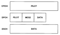
次いで、上記構成を有する基地局装置および通信端末装置の動作について、図1〜図3に加えて、図4および図5を参照して説明する。図4は、本発明の実施の形態1にかかる基地局装置に用いられるフレームフォーマットの一例を示す模式図である。図5は、本発明の実施の形態1にかかる通信端末装置に用いられるDPCHのフレームフォーマットの一例を示す模式図である。
【0064】
基地局装置において、CPICH変調・拡散部209では、図4に示すような既知信号(PILOT)は、変調された後、CPICHに割り当てられた拡散符号を用いて拡散処理される。これによりCPICH信号が生成される。生成されたCPICH信号は、多重部210に出力される。
【0065】
BCH変調・拡散部208では、CPICH信号の送信電力およびDSCH信号の送信電力を用いて送信電力情報が生成され、この送信電力情報および既知信号は、図4に示すように時間多重される。なお、図4に示すように、BCH信号、CPICH信号、DPCH信号およびDSCH信号は、同一周波数帯域に符号(コード)多重されていることが明かである。さらに、時間多重された信号は、変調された後、BCHに割り当てられた拡散符号を用いて拡散処理される。これによりBCH信号が生成される。生成されたBCH信号は、多重部210に出力される。
【0066】
DSCH変調・拡散部207により生成されたDSCH信号は、多重部210に出力される。DPCH変調・拡散部206−1〜206−Nにより生成されたDPCH信号は、多重部210に出力される。なお、DSCH変調・拡散部207により生成されるDSCH信号およびDPCH変調・拡散部206−1〜206−Nにより生成されるDPCH信号の詳細については後述する。
【0067】
多重部210では、BCH信号、CPICH信号、DSCH信号、および、通信端末装置1〜NのDPCH信号は、図4に示すように符号多重される。これにより、多重信号が生成される。生成された多重信号は、RF部202により所定の送信処理がなされた後、アンテナ201を介して送信される。このように送信された信号は、通信端末装置1〜N(図3に示した構成を有する通信端末装置)により受信される。
【0068】
通信端末装置1〜Nにおいて、上記のように基地局装置により送信された信号は、アンテナ301により受信された後、RF部302により受信処理される。受信処理された受信信号は、CPICH逆拡散部303、BCH逆拡散部306、DPCH逆拡散部311およびDSCH逆拡散部313に出力される。なお、DPCH逆拡散部311およびDSCH逆拡散部313における処理の詳細については後述する。
【0069】
CPICH逆拡散部303では、RF部302により受信処理された受信信号に対して、本通信端末装置に割り当てられた拡散符号を用いて逆拡散処理がなされた後、復調処理がなされる。これにより、復調信号すなわちCPICH信号が生成される。生成されたCPICH信号は、測定部304に出力される。
【0070】
測定部304では、生成されたCPICH信号の受信品質(例えばSIR等)が測定される。測定されたCPICH信号の受信品質は、SIR推定部305に出力される。
【0071】
BCH逆拡散部306では、RF部302により受信処理された受信信号に対して、BCHに割り当てられた拡散符号を用いて逆拡散処理がなされる。BCH復調部307では、BCH逆拡散部306により逆拡散された受信信号に対して復調処理がなされることにより、復調信号が生成される。さらに、生成された復調信号から送信電力情報が抽出され、抽出された送信電力情報は、SIR推定部305に出力される。
【0072】
SIR推定部305では、測定部304からのCPICH信号の受信品質、および、BCH復調部307からの送信電力情報を用いて、DSCH信号の受信品質(受信SIR)が推定される。なお、ここで推定されたDSCH信号の受信品質とは、基地局装置により送信されるDSCH信号の本通信端末装置における受信品質に相当する。具体的には、次に示す式によりDSCH信号の受信品質が測定される。
【0073】
DSCH信号のSIRの推定値[dB]=
CPICH信号の受信SIR[dB]+DSCH信号の送信電力[dB]
−CPICH信号の送信電力[dB] −▲1▼
SIR推定部305により推定されたDSCH信号の受信品質は、MCS1決定部308に出力される。
【0074】
MCS1決定部308では、SIR推定部305により推定されたDSCH信号の受信品質に基づいて、DSCH信号に用いることが可能な変調・符号化方式が決定される。具体的には、例えば、(推定されたDSCH信号の受信品質)対(所要サービス品質を実現するための変調・符号化方式)を示すテーブルをあらかじめ作成しておき、このテーブルを用いて、推定されたDSCH信号の受信品質に対応する変調・符号化方式を決定することができる。
【0075】
さらに、MCS1決定部308では、決定された変調・符号化方式を通知するための情報(すなわちMCS1)が作成される。作成されたMCS1は、多重部309に出力される。
【0076】
多重部309では、既知信号、送信データ、および、MCS1決定部308からのMCS1が多重されることにより、多重信号が生成される。すなわち、例えば、図5に示すように、PILOTの部分に既知信号が挿入され、MCS1の部分にMCS1が挿入され、DATAの部分に送信データが挿入されることにより、多重信号が生成される。生成された多重信号は、DPCH変調・拡散部310において、本通信端末装置のDPCHに割り当てられた拡散符号を用いて拡散処理される。これにより、DPCH信号が生成される。生成されたDPCH信号は、RF部302により送信処理がなされた後、アンテナ301を介して基地局装置に送信される。
【0077】
このように通信端末装置1〜Nにより送信された信号は、基地局装置により受信される。基地局装置において、上記のように通信端末装置1〜Nに送信された信号は、アンテナ201を介して受信された後、RF部202により受信処理される。RF部202により受信処理された受信信号は、DPCH逆拡散・復調部203−1〜203−Nに出力される。
【0078】
DPCH逆拡散・復調部203−1〜203−Nでは、まず、RF部202により受信処理された受信信号に対して、それぞれ、通信端末装置1〜NのDPCHに割り当てられた拡散符号を用いて逆拡散処理がなされる。さらに、DPCH逆拡散・復調部203−1〜203−Nでは、逆拡散処理により得られた信号に対して復調処理がなされることにより復調信号が生成される。この後、DPCH逆拡散・復調部203−1〜203−Nでは、復調信号からそれぞれ通信端末装置1〜NのMCS1が抽出される。抽出された通信端末装置1〜NのMCS1は、割り当て部204に出力される。
【0079】
割り当て部204では、DPCH逆拡散・復調部203−1〜203−NからのMCS1を用いて、通信端末装置1〜Nのうち最も高速にDSCH信号を送信できる通信端末装置が選択される。この後、割り当て部204からバッファ205およびDPCH変調・拡散部206−1〜206−Nに対して、DSCH信号の送信先としていずれの通信端末装置が選択されたが報知される。また、割り当て部204からDSCH変調・拡散部207に対して、DSCH信号の送信先としていずれの通信端末装置が選択されたか、および、この通信端末装置により通知された変調・符号化方式が報知される。
【0080】
バッファ205からDSCH変調・拡散部207に対して、割り当て部204から報知された通信端末装置に対応する送信データが出力される。バッファ205により出力された送信データは、DSCH変調・拡散部207において、バッ割り当て部204により報知された変調・符号化方式に対応する誤り訂正符号化処理、変調処理および拡散処理がなされる。これにより、割り当て部204により報知された通信端末装置のDSCH信号が生成される。生成されたDSCH信号は、多重部210に出力される。
【0081】
DPCH変調・拡散部206−1〜206−Nでは、それぞれ、通信端末装置1〜Nの送信データ、割り当て部204により報知された通信端末装置をDSCH信号の送信先とする旨を示すMCS2、および、既知信号を含む信号が生成される。すなわち、例えば、DPCH変調・拡散部206−1(206−N)では、図4を参照するに、既知信号がPILOT部分に挿入され、MCS2がMCS2の部分に挿入され、通信端末装置1(通信端末装置N)の送信データがDATAの部分に挿入される。
【0082】
さらに、DPCH変調・拡散部206−1〜206−Nでは、上記のように生成された信号は、変調処理がなされた後、それぞれ、通信端末装置1〜NのDPCHに割り当てられた拡散符号を用いて逆拡散処理がなされる。これにより、DPCH変調・拡散部206−1〜206−Nでは、それぞれ通信端末装置1〜NのDPCH信号が生成される。生成された通信端末装置1〜NのDPCH信号は、多重部210に出力される。
【0083】
多重部210では、DPCH変調・拡散部206−1〜206−Nのそれぞれにより生成された通信端末装置1〜NのDPCH信号、DSCH変調・拡散部207により生成されたDSCH信号、BCH変調・拡散部208により生成されたBCH信号、および、CPICH変調・拡散部209により生成されたCPICH信号が多重されることにより、多重信号が生成される。なお、CPICH信号およびBCH信号の生成については、上述した通りである。
【0084】
多重部210により生成された多重信号は、RF部202により送信処理された後、アンテナ201を介して送信される。このように送信された信号は、通信端末装置1〜Nにより受信される。
【0085】
通信端末装置1〜Nにおいて、上記のように基地局装置により送信された信号は、アンテナ301により受信され、RF部302により受信処理された後、CPICH逆拡散部303、BCH逆拡散部306、DPCH逆拡散部311およびDSCH逆拡散部313に出力される。BCH逆拡散部306およびCPICH逆拡散部303における処理については、上述した通りである。
【0086】
DPCH逆拡散部311では、RF部302により受信処理された信号に対して、本通信端末装置に割り当てられた拡散符号を用いた逆拡散処理がなされる。DPCH逆拡散部311により逆拡散処理された受信信号は、DPCH復調部312により復調される。これにより復調信号が生成される。
【0087】
さらに、DPCH復調部312では、生成された復調信号からMCS2が抽出される。DPCH復調部312では、このMCS2を用いて、基地局装置からいずれの通信端末装置に対してDSCH信号が送信されたかが認識される。DPCH復調部312からDSCH逆拡散部313およびDSCH復調部314に対して、認識結果が出力される。
【0088】
DSCH逆拡散部313では、DPCH復調部312からの認識結果により、本通信端末装置に対してDSCH信号が送信された旨が認識された場合には、RF部302により受信処理された受信信号に対して、MCS1決定部308で決定された変調・符号化方式に対応する逆拡散処理がなされる。逆拡散処理がなされた受信信号は、DSCH復調部314において、MCS1決定部308で決定された変調・符号化方式に対応する復調処理がなされる。これにより、受信データが生成される。以上が、本実施の形態にかかる基地局装置および通信端末装置の動作である。
【0089】
次いで、本実施の形態にかかる基地局装置および通信端末装置による効果について、上述した図19を参照して説明する。なお、基地局装置におけるCPICH信号の送信電力が50[dB]であり、基地局装置におけるDSCH信号の送信電力が45[dB]であり、通信端末装置におけるCPICH信号の受信品質が25[dB]であるものとする。
【0090】
この場合、通信端末装置においては、上記▲1▼式に従って、DSCH信号の受信品質は、25(CPICH信号の受信品質)+45(DSCH信号の送信電力)−50(CPICH信号の送信電力)=20[dB]として推定される。すなわち、図19に示すように、DSCH信号の受信品質が正確に推定される。
【0091】
このように、本実施の形態においては、基地局装置がDSCH信号とCPICH信号の送信電力に関する送信電力情報を通信端末装置に報知し、通信端末装置が、CPICH信号の受信品質、および、基地局装置から報知された送信電力情報を用いて、DSCH信号の受信品質を推定し、推定した受信品質に基づいてDSCH信号に用いることが可能な変調・符号化方式を決定する。これにより、通信端末装置は、DSCH信号の受信品質を正確に認識することができるので、DSCH信号の受信品質が所要品質を満たし、かつ、最良のDSCH信号(最適な変調・符号化方式が用いられたDSCH信号)を受信することができるように、DSCH信号に用いることが可能な変調・符号化方式を正確に決定することができる。
【0092】
したがって、通信端末装置に最良の品質で受信されるDSCH信号を送信できる基地局装置を提供することができるとともに、最良の品質でDSCH信号を受信できる通信端末装置を提供することができる。
【0093】
(実施の形態2)
本実施の形態では、基地局装置が変調・符号化方式を決定する場合について説明する。本実施の形態の概要について、図10を参照して説明する。図10は、本発明の実施の形態2にかかる基地局装置および通信端末装置による無線通信の様子の一例を示す模式図である。
【0094】
まず、図10において、通信端末装置1002がCPICH信号の受信品質を基地局装置に報知し、基地局装置1001は、通信端末装置1002におけるCPICH信号の受信品質と、基地局装置1001におけるDSCH信号とCPICH信号の送信電力の比とを用いて、通信端末装置1002におけるDSCH信号の受信品質を推定する。
【0095】
また、基地局装置1001は、推定されたDSCH信号の受信品質に基づいて、すべての通信端末装置のうち、下り回線(すなわちDSCH)の状況が良く、かつ、下り回線のサービス要求が良い(遅延時間が短い)通信端末装置(ここでは通信端末装置1002とする)を選択する。
【0096】
この後、基地局装置1001は、選択された通信端末装置1002におけるCPICH信号の受信品質に基づいて、DSCH信号に用いることが可能な変調・符号化方式を決定する。さらに、基地局装置1001は、選択された通信端末装置1002に対して、決定された変調・符号化方式を用いてDSCH信号を送信する。以上が、本実施の形態の概要である。
【0097】
次いで、上記のような基地局装置および通信端末装置の構成について説明する。まず、本実施の形態にかかる基地局装置の構成について、図6を参照して説明する。図6は、本発明の実施の形態2にかかる基地局装置の構成を示すブロック図である。なお、図6における実施の形態1(図2)と同様の構成については、図2におけるものと同一の符号を付して、詳しい説明を省略する。
【0098】
DPCH逆拡散・復調部601−1〜601−Nは、RF部202により所定の受信処理がなされた受信信号に対して、それぞれ、通信端末装置1〜通信端末装置NのDPCHに割り当てられた拡散符号を用いて逆拡散処理を行う。さらに、DPCH逆拡散・復調部601−1〜601−Nは、逆拡散処理により得られた信号に対して復調処理を行うことにより復調信号を生成し、生成された復調信号からCPICH信号の受信品質を示す情報を抽出しそれぞれ選択部602−1〜602−Nに出力する。
【0099】
選択部602−1〜602−Nは、それぞれ、DPCH逆拡散・復調部601−1〜601−NからのCPICH信号の受信品質を示す情報を用いて、通信端末装置1〜Nに対するDSCH信号に用いることが可能な変調・符号化方式を決定し、決定結果を割り当て部603に出力する。
【0100】
割り当て部603は、選択部602−1〜602−Nによる決定結果を用いて、通信端末装置1〜Nのうち最も高速にDSCH信号を送信できる通信端末装置を選択する点を除いて、実施の形態1における割り当て部204と同一の構成を有する。
【0101】
多重部604は、DPCH変調・拡散部206−1〜206−Nのそれぞれにより生成された通信端末装置1〜NのDPCH信号、DSCH変調・拡散部207により生成されたDSCH信号、および、CPICH変調・拡散部209により生成されたCPICH信号を多重することにより、多重信号を生成する。
【0102】
次に、本実施の形態にかかる通信端末装置の構成について、図7を参照して説明する。図7は、本発明の実施の形態2にかかる通信端末装置の構成を示すブロック図である。なお、図7における実施の形態1(図3)と同様の構成については、図3におけるものと同一の符号を付して、詳しい説明を省略する。多重部701は、既知信号、送信データ、および、測定部304からのCPICH信号の受信品質を示す情報を多重することにより、多重信号を生成する。
【0103】
次いで、上記構成を有する基地局装置および通信端末装置の動作について、図6および図7に加えて、図8および図9を参照して説明する。図8は、本発明の実施の形態2にかかる基地局装置に用いられるフレームフォーマットの一例を示す模式図である。図9は、本発明の実施の形態2にかかる通信端末装置に用いられるDPCHのフレームフォーマットの一例を示す模式図である。なお、本実施の形態における実施の形態1と同様になされる動作については、詳しい説明を省略する。
【0104】
基地局装置において、多重部604では、CPICH信号、DSCH信号、および、通信端末装置1〜NのDPCH信号は、図8に示すように符号多重される。これにより、多重信号が生成される。生成された多重信号は、RF部202およびアンテナ201を介して送信される。このように送信された信号は、通信端末装置1〜N(図7に示した構成を有する通信端末装置)により受信される。
【0105】
通信端末装置1〜Nにおいて、測定部304では、CPICH信号の受信品質が測定され、測定されたCPICH信号の受信品質を示す情報が生成される。CPICH信号の受信品質を示す情報は、多重部701に出力される。
【0106】
多重部701では、既知信号、送信データ、および、CPICH信号の受信品質を示す情報が多重されることにより、多重信号が生成される。すなわち、例えば、図9に示すように、PILOTの部分に既知信号が挿入され、SIRの部分にCPICH信号の受信品質が挿入され、DATAの部分に送信データが挿入されることにより、多重信号が生成される。以後、上述したように、DPCH変調・拡散部310によりDPCH信号が生成され、生成されたDPCH信号は、RF部302およびアンテナ301を介して基地局装置に送信される。
【0107】
このように通信端末装置1〜Nにより送信された信号は、基地局装置により受信される。基地局装置において、上記のように通信端末装置1〜Nに送信された信号は、アンテナ201およびRF部202を介して、DPCH逆拡散・復調部601−1〜601−Nに出力される。
【0108】
DPCH逆拡散・復調部601−1〜601−Nでは、RF部202からの受信信号に対して逆拡散処理がなされた後、逆拡散処理により得られた信号に対して復調処理が行われることにより復調信号が生成される。さらに、生成された復調信号からCPICH信号の受信品質を示す情報が抽出される。DPCH逆拡散・復調部601−1〜601−Nのそれぞれにより抽出された通信端末装置1〜NのCPICH信号の受信品質を示す情報は、それぞれ選択部602−1〜602−Nに出力される。
【0109】
選択部602−1〜602−Nでは、それぞれ、DPCH逆拡散・復調部601−1〜601−NからのCPICH信号の受信品質を示す情報、および、CPICH信号およびDSCH信号の送信電力を用いて、通信端末装置1〜NにおけるDSCH信号の受信品質が推定される。DSCH信号の受信品質の推定方法は、実施の形態1(図3)における通信端末装置のSIR推定部305によるものと同一である。
【0110】
さらに、選択部602−1〜602−Nでは、推定されたDSCH信号の受信品質に基づいて、それぞれ、通信端末装置1〜Nに対するDSCH信号に用いることが可能な変調・符号化方式が決定される。変調・符号化方式の決定方法は、実施の形態1(図3)における通信端末装置のMCS1決定部308によるものと同一である。選択部602−1〜602−Nのそれぞれにより決定された通信端末装置1〜Nに対応する変調・符号化方式は、割り当て部603に出力される。
【0111】
割り当て部603では、選択部602−1〜602−Nのそれぞれからの通信端末装置1〜Nに対応する変調・符号化方式を用いて、通信端末装置1〜Nのうち最も高速にDSCH信号を送信できる通信端末装置が選択される。この後、割り当て部603からバッファ205およびDPCH変調・拡散部206−1〜206−Nに対して、DSCH信号の送信先としていずれの通信端末装置が選択されたが報知される。また、割り当て部603からDSCH変調・拡散部207に対して、DSCH信号の送信先としていずれの通信端末装置が選択されたか、および、この通信端末装置により通知された変調・符号化方式が報知される。
【0112】
以後、バッファ205、DSCH変調・拡散部207、および、DPCH変調・拡散部206−1〜206−Nでは、実施の形態1で説明したような処理がなされる。
【0113】
多重部604では、DPCH変調・拡散部206−1〜206−Nのそれぞれにより生成された通信端末装置1〜NのDPCH信号、DSCH変調・拡散部207により生成されたDSCH信号、および、CPICH変調・拡散部209により生成されたCPICH信号が多重されることにより、多重信号が生成される。
【0114】
生成された多重信号は、RF部202およびアンテナ201を介して、通信端末装置1〜Nに送信される。このように送信された信号は、通信端末装置1〜Nにより受信される。以後の通信端末装置1〜Nにおける処理については、実施の形態1におけるものと同様であるので、詳しい説明を省略する。
【0115】
このように、本実施の形態においては、通信端末装置が、CPICH信号の受信品質を基地局装置に報知し、基地局装置は、通信端末装置により報知されたCPICH信号の受信品質と、基地局装置におけるDSCH信号およびCPICH信号の送信電力とを用いて、通信端末装置におけるDSCH信号の受信品質を推定する。さらに、基地局装置は、推定された通信端末装置におけるDSCH信号の受信品質に基づいて、DSCH信号に用いることが可能な変調・符号化方式を決定する。これにより、基地局装置は、通信端末装置におけるDSCH信号の受信品質を正確に認識することができるので、DSCH信号の受信品質が所要品質を満たし、かつ、最良のDSCH信号(最適な変調・符号化方式が用いられたDSCH信号)を受信することができるように、DSCH信号に用いることが可能な変調・符号化方式を正確に決定することができる。
【0116】
したがって、通信端末装置に最良の品質で受信されるDSCH信号を送信できる基地局装置を提供することができるとともに、最良の品質でDSCH信号を受信できる通信端末装置を提供することができる。
【0117】
(実施の形態3)
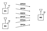
実施の形態3および実施の形態4では、通信端末装置が、複数の基地局装置がカバーするエリアに存在する場合について説明する。本実施の形態では、通信端末装置が、DSCH信号の要求先となる基地局装置、および、変調・符号化方式を決定する場合について説明する。まず、本実施の形態の概要について図11を参照して説明する。図11は、本発明の実施の形態3にかかる基地局装置および通信端末装置による無線通信の様子の一例を示す模式図である。
【0118】
図11において、通信端末装置1103は、複数の基地局装置がカバーするエリア(ここでは、基地局装置1101がカバーするエリアおよび基地局装置1102がカバーするエリア)に存在する。なお、図示されていないが、通信端末装置1103以外の通信端末装置も、基地局装置1101がカバーするエリアおよび基地局装置1102がカバーするエリアに存在しているものとする。
【0119】
まず、基地局装置1101および基地局装置1102は、それぞれ、固有のBCH信号を送信する。また、基地局装置1101および基地局装置1102は、それぞれ、固有のCPICH信号を送信する。なお、BCH信号およびCPICH信号は実施の形態1におけるものと同一である。
【0120】
通信端末装置1103は、基地局装置1101により送信されたCPICH信号の受信品質、および、基地局装置1101により送信されたBCH信号に含まれた送信電力情報を用いて、基地局装置1101により送信されるDSCH信号の受信品質を推定する。また、通信端末装置1103は、基地局装置1102により送信されたCPICH信号の受信品質、および、基地局装置1102により送信されたBCH信号に含まれた送信電力情報を用いて、基地局装置1102により送信されるDSCH信号の受信品質を推定する。
【0121】
さらに、通信端末装置1103は、DSCH信号の要求先として、推定された受信品質が最良となったDSCH信号に対応する基地局装置(ここでは、基地局装置1101とする。)を選択する。また、通信端末装置1103は、選択された基地局装置1101に対応するDSCH信号の推定された受信品質に基づいて、このDSCH信号に用いることが可能な変調・符号化方式を決定する。
【0122】
この後、通信端末装置1103は、DSCH信号の要求先を通知するための情報(以下「基地局選択情報」という。)と、MCS1(すなわち、決定した変調・符号化方式を通知するための情報)とを含むDPCH信号を送信する。
【0123】
基地局装置1101および基地局装置1102は、各通信端末装置からのDPCH信号を受信し、DPCH信号に含まれた基地局選択情報を用いて、自局にDSCH信号の送信を要求している通信端末装置を認識する。さらに、基地局装置1101および基地局装置1102は、自局にDSCH信号の送信を要求しているすべての通信端末装置のうち、下り回線(すなわちDSCH)の状況が良く、かつ、下り回線のサービス要求が良い(遅延時間が短い)通信端末装置を選択する。
【0124】
この後、基地局装置1101および基地局装置1102は、選択した通信端末装置に対して、この通信端末装置により通知された変調・符号化方式を用いてDSCH信号を送信する。ここでは、通信端末装置1103は、基地局装置1101からDSCH信号を受信することになる。以上が、本実施の形態の概要である。
【0125】
次いで、上記のような基地局装置および通信端末装置の構成について説明する。まず、本実施の形態にかかる通信端末装置の構成について、図12を参照して説明する。図12は、本発明の実施の形態3にかかる通信端末装置の構成を示すブロック図である。なお、図12における実施の形態1(図3)と同様の構成については、図3におけるものと同一の符号を付して、詳しい説明を省略する。
【0126】
図12において、CPICH逆拡散部1201は、RF部302により受信処理された受信信号に対して、各基地局装置のCPICHに割り当てられた拡散符号を用いて逆拡散処理を行うことにより、基地局装置毎にCPICH信号を生成する。
【0127】
測定部1202は、CPICH逆拡散部1201により生成された基地局装置毎のCPICH信号の受信品質(例えばSIR等)を測定し、測定された基地局装置毎のCPICH信号の受信品質をSIR推定部1205に出力する。
【0128】
BCH逆拡散部1203は、RF部302により受信処理された受信信号に対して、各基地局装置のBCHに割り当てられた拡散符号を用いて逆拡散処理を行う。BCH復調部1204は、BCH逆拡散部1203により逆拡散処理された受信信号に対して復調処理を行うことにより、基地局装置毎の復調信号を生成する。また、BCH復調部1204は、生成された基地局装置毎の復調信号から送信電力情報を抽出し、抽出した基地局装置毎の送信電力情報をSIR推定部1205に出力する。
【0129】
SIR推定部1205は、測定部1202からの基地局装置毎のCPICH信号の受信品質、および、BCH復調部1204からの基地局装置毎の送信電力情報を用いて、DSCH信号の受信品質を基地局装置毎に推定する。SIR推定部1205は、推定された基地局装置毎のDSCH信号の受信品質を、基地局決定部1206およびMCS1決定部1207に出力する。
【0130】
基地局決定部1206は、推定された基地局装置毎のDSCH信号の受信品質を用いて、DSCH信号の要求先として、推定された受信品質が最良となったDSCH信号に対応する基地局装置を選択する。この基地局決定部1206は、選択結果をMCS1決定部1207に出力するとともに、DSCH信号の要求先を通知するための基地局選択情報を生成して多重部1208に出力する。
【0131】
MCS1決定部1207は、SIR推定部1205により推定された基地局装置毎のDSCH信号の受信品質、および、基地局決定部1206からの選択結果に基づいて、まず、DSCH信号の要求先として選択された基地局装置に対応するDSCH信号の受信品質を取り出す。さらに、MCS1決定部1207は、取り出した受信品質を用いて、DSCH信号に用いることが可能な変調・符号化方式を決定し、決定した変調・符号化方式を通知するためのMCS1を生成する。
【0132】
多重部1208は、送信データ、基地局選択情報およびMCS1を多重することにより、多重信号を生成する。
【0133】
次に、本実施の形態にかかる基地局装置の構成について、図13を参照して説明する。図13は、本発明の実施の形態3にかかる基地局装置の構成を示すブロック図である。なお、図13における実施の形態1(図2)と同様の構成については、図2におけるものと同一の符号を付して、詳しい説明を省略する。
【0134】
図13において、DPCH逆拡散・復調部1301−1〜1301−Nは、それぞれ、復調信号からMCS1および基地局選択情報を抽出して判定部1302−1〜1302−Nに出力する点を除いて、実施の形態1(図2)におけるDPCH逆拡散・復調部203−1〜203−Nと同様の構成を有する。
【0135】
判定部1302−1〜1302−Nは、それぞれ、DPCH逆拡散・復調部1301−1〜1301−Nからの基地局選択情報が自局にDSCH信号の送信を要求している旨を示す場合には、DPCH逆拡散・復調部1301−1〜1301−NからのMCS1を割り当て部204に出力する。
【0136】
次いで、上記構成を有する基地局装置および通信端末装置の動作について、図12および図13に加えて、図14を参照して説明する。図14は、本発明の実施の形態3にかかる通信端末装置に用いられるDPCHのフレームフォーマットの一例を示す模式図である。なお、本実施の形態における実施の形態1と同様になされる動作については、詳しい説明を省略する。
【0137】
通信端末装置1〜Nにおいて、基地局装置により送信された信号は、上述したように、アンテナ301およびRF部302を介して、CPICH逆拡散部1201、BCH逆拡散部1203、DPCH逆拡散部311およびDSCH逆拡散部313に出力される。DPCH逆拡散部311およびDSCH逆拡散部313における処理は、実施の形態1で説明した通りである。
【0138】
CPICH逆拡散部1201では、RF部302により受信処理された受信信号に対して、各基地局装置のCPICHに割り当てられた拡散符号を用いて逆拡散処理が行われる。これにより、基地局装置毎にCPICH信号が生成される。
【0139】
測定部1202では、CPICH逆拡散部1201により生成された基地局装置毎のCPICH信号の受信品質(例えばSIR等)が測定される。測定された基地局装置毎のCPICH信号の受信品質は、SIR推定部1205に出力される。
【0140】
BCH逆拡散部1203では、RF部302により受信処理された受信信号に対して、各基地局装置のBCHに割り当てられた拡散符号を用いて逆拡散処理が行われる。BCH復調部1204では、BCH逆拡散部1203により逆拡散処理された受信信号に対して復調処理が行われることにより、基地局装置毎の復調信号が生成される。さらに、生成された基地局装置毎の復調信号から送信電力情報が抽出され、抽出された基地局装置毎の送信電力情報は、SIR推定部1205に出力される。なお、送信電力情報については、実施の形態1で説明したものと同様なものである。
【0141】
SIR推定部1205では、測定部1202からの基地局装置毎のCPICH信号の受信品質、および、BCH復調部1204からの基地局装置毎の送信電力情報を用いて、基地局装置毎にDSCH信号の受信品質が推定される。推定された基地局装置毎のDSCH信号の受信品質は、基地局決定部1206およびMCS1決定部1207に出力される。
【0142】
基地局決定部1206では、推定された基地局装置毎のDSCH信号の受信品質を用いて、DSCH信号の要求先として、推定された受信品質が最良となったDSCH信号に対応する基地局装置が選択される。さらに、選択結果に基づいて、DSCH信号の要求先を通知するための基地局選択情報が生成される。この後、選択結果がMCS1決定部1207に出力されるとともに、生成された基地局選択情報が多重部1208に出力される。
【0143】
MCS1決定部1207では、SIR推定部1205により推定された基地局装置毎のDSCH信号の受信品質、および、基地局決定部1206からの選択結果に基づいて、まず、DSCH信号の要求先として選択された基地局装置に対応するDSCH信号の受信品質が取り出される。さらに、取り出された受信品質を用いて、DSCH信号に用いることが可能な変調・符号化方式が決定され、決定された変調・符号化方式を通知するためのMCS1が生成される。なお、MCS1の生成については、実施の形態1におけるMCS1決定部308によるものと同様であるので、詳しい説明を省略する。生成されたMCS1は、多重部1208に出力される。
【0144】
多重部1208では、既知信号、送信データ、MCS1決定部1207からのMCS1、および、基地局決定部1206からの基地局選択情報が多重されることにより、多重信号が生成される。すなわち、例えば、図14に示すように、PILOTの部分に既知信号が挿入され、MCS1の部分にMCS1が挿入され、BS番号の部分に基地局選択情報が挿入され、DATAの部分に送信データが挿入されることにより、多重信号が生成される。生成された多重信号は、実施の形態1で説明したように、DPCH変調・拡散部310、RF部302およびアンテナ301を介して送信される。
【0145】
このように通信端末装置1〜Nにより送信された信号は、基地局装置により受信される。基地局装置において、上記のように通信端末装置1〜Nに送信された信号は、アンテナ201およびRF部202を介して、DPCH逆拡散・復調部1301−1〜1301−Nに出力される。
【0146】
DPCH逆拡散・復調部1301−1〜1301−Nでは、それぞれ、まず、実施の形態1(図2)のDPCH逆拡散・復調部203−1〜203−Nにおけるものと同様の処理がなされることにより、復調信号が生成される。さらに、DPCH逆拡散・復調部1301−1〜1301−Nでは、復調信号からMCS1および基地局選択情報が抽出される。DPCH逆拡散・復調部1301−1〜1301−Nにより抽出されたMCS1および基地局選択情報は、それぞれ、判定部1302−1〜1302−Nに出力される。
【0147】
判定部1302−1〜1302−Nでは、まず、それぞれDPCH逆拡散・復調部1301−1〜1301−Nからの基地局選択情報が、自局にDSCH信号の送信を要求する旨を示しているか否かの判定がなされる。判定部1302−1〜1302−Nのうち、自局にDSCH信号の送信を要求する旨を示す基地局選択情報が得られた判定部により、その判定部が有するMCS1が割り当て部204に出力される。
【0148】
割り当て部204では、実施の形態1で説明したものと同様の処理がなされることにより、通信端末装置1〜Nのうち最も高速にDSCH信号を送信できる通信端末装置が選択される。以後、実施の形態1と同様に、多重部210により多重信号が生成され、生成された多重信号は、RF部202およびアンテナ201を介して通信端末装置に送信される。
【0149】
次いで、本実施の形態にかかる基地局装置および通信端末装置による効果について、具体例を挙げて説明する。基地局装置AにおけるDSCH信号の送信電力とCPICH信号の送信電力が同じであり、基地局装置BにおけるDSCH信号の送信電力がCPICH信号の送信電力より10[dB]だけ低いものとし、さらに、通信端末装置においては、基地局装置Aおよび基地局装置Bにより送信されたCPICH信号の受信品質が同一であるものとする。
【0150】
この場合には、基地局装置Aにより送信されたDSCH信号の受信品質は、50+0=50[dB]として推定され、基地局装置Bにより送信されたDSCH信号の受信品質は、50−10=40[dB]として推定される。この結果、通信端末装置は、DSCH信号の要求先として、基地局装置Aを選択する。
【0151】
したがって、CPICH信号の受信品質は同一であっても、通信端末装置は、DSCH信号の要求先として、より受信品質の良いDSCH信号を送信する基地局装置を選択することができる。
【0152】
このように、本実施の形態においては、各基地局装置は、CPICH信号、および、DSCH信号とCPICH信号の送信電力に関する送信電力情報を通信端末装置に報知し、通信端末装置は、各基地局装置により送信されたCPICH信号および送信電力情報を用いて、各基地局装置により送信されるDSCH信号の受信品質を推定する。さらに、通信端末装置は、すべての基地局装置のうち、推定された受信品質が最良となったDSCH信号に対応する基地局装置を、DSCH信号の要求先として選択する。これにより、通信端末装置は、各基地局装置により送信されるDSCH信号の受信品質を正確に推定することができるので、DSCH信号の要求先として、最良の品質で受信できるDSCH信号を送信する基地局装置を正確に選択することができる。
【0153】
さらに、通信端末装置は、選択された基地局装置に対応するDSCH信号の推定された受信品質に基づいて、このDSCH信号に用いることが可能な変調・符号化方式を決定する。これにより、通信端末装置は、選択された基地局装置により送信されるDSCH信号に用いることが可能な変調・符号化方式を正確に決定することができる。
【0154】
したがって、通信端末装置に最良の品質で受信されるDSCH信号を送信できる基地局装置を提供することができるとともに、最良の品質でDSCH信号を受信できる通信端末装置を提供することができる。
【0155】
(実施の形態4)
本実施の形態では、通信端末装置がDSCH信号の要求先となる基地局装置を決定し、基地局装置が変調・符号化方式を決定する場合について説明する。本発明の概要について、再度図11を参照して説明する。
【0156】
図11において、まず、基地局装置1101および基地局装置1102は、それぞれ、固有のBCH信号を送信する。また、基地局装置1101および基地局装置1102は、それぞれ、固有のCPICH信号を送信する。なお、BCH信号およびCPICH信号は実施の形態1におけるものと同一である。
【0157】
通信端末装置1103は、基地局装置1101により送信されたCPICH信号の受信品質、および、基地局装置1101により送信されたBCH信号に含まれた送信電力情報を用いて、基地局装置1101により送信されるDSCH信号の受信品質を推定する。また、通信端末装置1103は、基地局装置1102により送信されたCPICH信号の受信品質、および、基地局装置1102により送信されたBCH信号に含まれた送信電力情報を用いて、基地局装置1102により送信されるDSCH信号の受信品質を推定する。
【0158】
さらに、通信端末装置1103は、DSCH信号の要求先として、推定された受信品質が最良となったDSCH信号に対応する基地局装置(ここでは、基地局装置1101とする。)を選択し、基地局装置1101に対して、推定されたDSCH信号の受信品質を報知する。
【0159】
選択された基地局装置1101は、通信端末装置により報知されたDSCH信号の受信品質に基づいて、すべての受信品質のうち、下り回線(すなわちDSCH)の状況が良く、かつ、下り回線のサービス要求が良い(遅延時間が短い)通信端末装置(ここでは通信端末装置1103とする)を選択する。
【0160】
この後、基地局装置1101は、選択された通信端末装置1103におけるCPICH信号の受信品質に基づいて、DSCH信号に用いることが可能な変調・符号化方式を決定する。さらに、基地局装置1101は、選択された通信端末装置1002に対して、決定された変調・符号化方式を用いてDSCH信号を送信する。以上が、本実施の形態の概要である。
【0161】
次いで、上記のような基地局装置および通信端末装置の構成について説明する。まず、本実施の形態にかかる通信端末装置の構成について、図15を参照して説明する。図15は、本発明の実施の形態4にかかる通信端末装置の構成を示すブロック図である。なお、図15における実施の形態3(図12)と同様の構成については、図12におけるものと同一の符号を付して、詳しい説明を省略する。
【0162】
図15において、基地局決定部1501は、SIR推定部1205により推定された基地局装置毎のDSCH信号の受信品質を用いて、DSCH信号の要求先として、推定された受信品質が最良となったDSCH信号に対応する基地局装置を選択する。さらに、基地局決定部1501は、DSCH信号の要求先を通知するための基地局選択情報を生成し、この基地局選択情報と、選択された基地局装置により送信されるDSCH信号の推定された受信品質を示す情報とを多重部1502に出力する。
【0163】
多重部1502は、既知信号、送信データ、ならびに、基地局決定部1501からのDSCH信号の推定された受信品質を示す情報および基地局選択情報を多重することにより、多重信号を生成する。
【0164】
次に、本実施の形態にかかる基地局装置の構成について、図16を参照して説明する。図16は、本発明の実施の形態4にかかる基地局装置の構成を示すブロック図である。なお、図16における実施の形態3(図13)と同様の構成については、図13におけるものと同一の符号を付して、詳しい説明を省略する。
【0165】
図16において、DPCH逆拡散・復調部1601−1〜1601−Nは、それぞれ、復調信号から基地局選択情報およびDSCH信号の受信品質を示す情報を抽出して判定部1602−1〜1602−Nに出力する点を除いて、実施の形態3におけるDPCH逆拡散・復調部1301−1〜1301−Nと同様の構成を有する。
【0166】
判定部1602−1〜1602−Nは、それぞれ、DPCH逆拡散・復調部1601−1〜1601−Nからの基地局選択情報が自局にDSCH信号の送信を要求している旨を示す場合には、DPCH逆拡散・復調部1601−1〜1601−NからのDSCHの受信品質を示す情報を、選択部1603−1〜1603−Nに出力する。
【0167】
選択部1603−1〜1603−Nは、それぞれ、DPCH逆拡散・復調部1601−1〜1601−NからのDSCH信号の受信品質を示す情報を用いて、通信端末装置1〜Nに対するDSCH信号に用いることが可能な変調・符号化方式を決定し、決定結果を割り当て部1604に出力する。
【0168】
割り当て部1604は、選択部1603−1〜1603−Nによる決定結果を用いて、通信端末装置1〜Nのうち最も高速にDSCH信号を送信できる通信端末装置を選択する点を除いて、実施の形態1における割り当て部204と同一の構成を有する。
【0169】
次いで、上記構成を有する基地局装置および通信端末装置の動作について、図15および図16に加えて、図17を参照して説明する。図17は、本発明の実施の形態4にかかる通信端末装置に用いられるDPCHのフレームフォーマットの一例を示す模式図である。なお、本実施の形態における実施の形態1と同様になされる動作については、詳しい説明を省略する。
【0170】
通信端末装置1〜Nにおいて、基地局決定部1501では、SIR推定部1205により推定された基地局装置毎のDSCH信号の受信品質を用いて、DSCH信号の要求先として、推定された受信品質が最良となったDSCH信号に対応する基地局装置が選択される。さらに、基地局決定部1501では、DSCH信号の要求先を通知するための基地局選択情報が生成し、この基地局選択情報と、選択された基地局装置により送信されるDSCH信号の推定された受信品質を示す情報とが多重部1502に出力される。
【0171】
多重部1502では、既知信号、送信データ、DSCH信号の受信品質を示す情報、および、基地局選択情報が多重されることにより、多重信号が生成される。すなわち、例えば、図17に示すように、PILOTの部分に既知信号が挿入され、SIRの部分にDSCH信号の受信品質が挿入され、BS番号の部分に基地局選択情報が挿入され、DATAの部分に送信データが挿入されることにより、多重信号が生成される。以後、上述したように、DPCH変調・拡散部310によりDPCH信号が生成され、生成されたDPCH信号は、RF部302およびアンテナ301を介して基地局装置に送信される。
【0172】
このように通信端末装置1〜Nにより送信された信号は、基地局装置により受信される。基地局装置において、上記のように通信端末装置1〜Nに送信された信号は、アンテナ201およびRF部202を介して、DPCH逆拡散・復調部1601−1〜1601−Nに出力される。
【0173】
DPCH逆拡散・復調部1601−1〜1601−Nでは、それぞれ、復調信号から基地局選択情報およびDSCH信号の受信品質を示す情報が抽出される。DPCH逆拡散・復調部1601−1〜1601−Nにより抽出された基地局選択情報およびDSCH信号の受信品質を示す情報は、それぞれ、判定部1602−1〜1602−Nに出力される。
【0174】
判定部1602−1〜1602−Nでは、まず、それぞれDPCH逆拡散・復調部1601−1〜1601−Nからの基地局選択情報が、自局にDSCH信号の送信を要求する旨を示しているか否かの判定がなされる。判定部1602−1〜1602−Nのうち、自局にDSCH信号の送信を要求する旨を示す基地局選択情報が得られた判定部により、その判定部が有するDSCHの受信品質を示す情報が、後段に設けられた選択部に出力される。
【0175】
選択部1603−1〜1603−Nのうち前段の判定部からDSCH信号の受信信号が出力された選択部では、DSCH信号の受信品質に基づいて、DSCH信号に用いることが可能な変調・符号化方式が決定される。なお、変調・符号化方式の決定方法については、実施の形態1(図3)におけるMCS1決定部308によるものと同様であるので、詳細な説明を省略する。選択部1603−1〜1603−Nにおける決定結果は、割り当て部1604に出力される。
【0176】
割り当て部1604では、選択部1603−1〜1603−Nのそれぞれからの通信端末装置1〜Nに対応する変調・符号化方式を用いて、通信端末装置1〜Nのうち最も高速にDSCH信号を送信できる通信端末装置が選択される。以後、実施の形態1で説明したように、多重部210により多重信号が生成される。生成された多重信号は、RF部202およびアンテナ201を介して通信端末装置に送信される。
【0177】
このように、本実施の形態においては、各基地局装置は、CPICH信号、および、DSCH信号とCPICH信号の送信電力に関する情報を通信端末装置に報知し、通信端末装置は、各基地局装置により送信されたCPICH信号および送信電力を用いて、各基地局装置により送信されるDSCH信号の受信品質を推定する。さらに、通信端末装置は、すべての基地局装置のうち、推定された受信品質が最良となったDSCH信号に対応する基地局装置を、DSCH信号の要求先として選択する。これにより、通信端末装置は、各基地局装置により送信されるDSCH信号の受信品質を正確に推定することができるので、DSCH信号の要求先として、最良の品質で受信できるDSCH信号を送信する基地局装置を正確に選択することができる。
【0178】
さらに、通信端末装置は、選択された基地局装置に対して、この基地局装置により送信されるDSCH信号の推定された受信品質を報知する。これにより、基地局装置は、通信端末装置に送信するDSCH信号に用いることが可能な変調・符号化方式を正確に決定することができる。
【0179】
したがって、通信端末装置に最良の品質で受信されるDSCH信号を送信できる基地局装置を提供することができるとともに、最良の品質でDSCH信号を受信できる通信端末装置を提供することができる。
【0180】
なお、上記実施の形態1〜4においては、送信側におけるDSCH信号とCPICH信号の送信電力と、受信側におけるCPICH信号の受信品質とを用いて、受信側におけるDSCH信号の受信品質を推定し、さらに、推定されたDSCH信号の受信品質に基づいて、送信側におけるDSCH信号に用いることが可能な変調・符号化方式を決定する場合について説明した。ただし、本発明は、以下の条件を満たす限りにおいては、データチャネル(上記実施の形態では「DSCH」)の名前、データチャネルを推定するために用いる制御チャネル(上記実施の形態では「CPICH」)、およびこれらのチャネルにより通信される情報の種類等が、適宜変更された場合についても適用可能なものである。すなわち、データチャネルと制御チャネルは、時間多重または符号多重されている必要がある。
【0181】
また、上記実施の形態1〜4においては、送信側が、送信側のデータチャネルおよび制御チャネルの送信電力を受信側に報知するための報知チャネルとして、BCHを用いた場合について説明したが、データチャネルおよび制御チャネルに多重(時間多重または符号多重)されるチャネルDPCH等のその他のチャネルを、報知チャネルとして用いることも可能である。
【0182】
さらに、上記実施の形態3および4においては、通信端末装置が、2つの基地局装置がカバーするエリアに存在する場合を例にとり説明したが、本発明は、通信端末装置が、1つの基地局装置がカバーするエリア、または、3つ以上の基地局装置がカバーするエリアに存在する場合についても適用可能なものである。
【0183】
【発明の効果】
以上説明したように、本発明によれば、最良の品質でDSCH信号を受信できる通信端末装置、または、通信端末装置に最良の品質で受信されるDSCH信号を送信できる基地局装置を提供することができる。
【図面の簡単な説明】
【図1】本発明の実施の形態1にかかる基地局装置および通信端末装置による無線通信の様子の一例を示す模式図
【図2】上記実施の形態1にかかる基地局装置の構成を示すブロック図
【図3】上記実施の形態1にかかる通信端末装置の構成を示すブロック図
【図4】上記実施の形態1にかかる基地局装置に用いられるフレームフォーマットの一例を示す模式図
【図5】上記実施の形態1にかかる通信端末装置に用いられるDPCHのフレームフォーマットの一例を示す模式図
【図6】本発明の実施の形態2にかかる基地局装置の構成を示すブロック図
【図7】上記実施の形態2にかかる通信端末装置の構成を示すブロック図
【図8】上記実施の形態2にかかる基地局装置に用いられるフレームフォーマットの一例を示す模式図
【図9】上記実施の形態2にかかる通信端末装置に用いられるDPCHのフレームフォーマットの一例を示す模式図
【図10】上記実施の形態2にかかる基地局装置および通信端末装置による無線通信の様子の一例を示す模式図
【図11】本発明の実施の形態3にかかる基地局装置および通信端末装置による無線通信の様子の一例を示す模式図
【図12】上記実施の形態3にかかる通信端末装置の構成を示すブロック図
【図13】上記実施の形態3にかかる基地局装置の構成を示すブロック図
【図14】上記実施の形態3にかかる通信端末装置に用いられるDPCHのフレームフォーマットの一例を示す模式図
【図15】本発明の実施の形態4にかかる通信端末装置の構成を示すブロック図
【図16】上記実施の形態4にかかる基地局装置の構成を示すブロック図
【図17】上記実施の形態4にかかる通信端末装置に用いられるDPCHのフレームフォーマットの一例を示す模式図
【図18】従来の基地局装置および通信端末装置による無線通信の様子の一例を示す模式図
【図19】通信端末装置におけるDSCH信号およびCPICH信号の受信品質を示す模式図
【符号の説明】
203−1〜203−N DPCH逆拡散・復調部
204 割り当て部
303 CPICH逆拡散部
304 測定部
305 SIR推定部
308 MCS1決定部
313 DSCH逆拡散部
314 DSCH復調部[0001]
TECHNICAL FIELD OF THE INVENTION
The present invention relates to a communication device used in a digital mobile communication system, and more particularly, to a base station device and a communication terminal device used in a W-CDMA (Wide band-Code Division Multiple Access) digital mobile communication system.
[0002]
[Prior art]
In recent years, in a W-CDMA digital mobile communication system, high-speed data communication (downlink high-speed packet communication) using a downlink has been proposed. Hereinafter, high-speed data communication using the downlink will be described with reference to FIG. FIG. 18 is a schematic diagram showing a state of a system in which high-speed data communication using a downlink is performed.
[0003]
In FIG. 18, it is assumed that
[0004]
Hereinafter, for simplification of description, a signal communicated using the CPICH is referred to as a “CPICH signal”. Similarly, a signal communicated using a downlink shared channel (DSCH) is referred to as a “DSCH signal”, and a signal communicated using a dedicated physical channel (DPCH) is referred to as a “DPCH signal”. And
[0005]
[0006]
Thereafter, the
[0007]
In addition, not only the
[0008]
The
[0009]
Thereafter,
[0010]
In this manner, the
[0011]
When the
[0012]
[Problems to be solved by the invention]
However, in the above-described conventional high-speed data communication using the downlink, actually, the transmission power of the DSCH signal and the transmission power of the CPICH signal in the base station device are different for each base station device. Problem.
[0013]
First, the communication terminal apparatus determines a modulation scheme and an error correction coding scheme that can be used for the DSCH signal based on the reception quality of the CPICH signal. When the transmission power is smaller than the transmission power of the CPICH signal, a method that is higher in speed than the modulation method and the error correction coding method for satisfying the required quality of the DSCH signal is selected. For this reason, the reception quality of the DSCH signal in the communication terminal apparatus may be lower than the required quality.
[0014]
As a specific example, since the transmission power of the DSCH signal in the base station apparatus is smaller than the transmission power of the CPICH signal, the reception quality of the CPICH signal in the communication terminal apparatus becomes 25 [dB] as shown in FIG. The case where the reception quality of the DSCH signal in the device becomes 20 [dB] will be described.
[0015]
In this case, the communication terminal apparatus selects the QPSK modulation scheme as the modulation scheme used for the DSCH signal based on the reception quality of the CPICH signal so that the reception quality of the DSCH signal satisfies the required quality. However, since the actual DSCH reception quality is lower than the CPICH signal by 5 [dB], the reception quality of the DSCH signal using the QPSK modulation is lower than the required quality. In order for a communication terminal apparatus to receive a DSCH signal satisfying required quality, it is necessary to receive a DSCH signal using BPSK modulation.
[0016]
Conversely, when the transmission power of the DSCH signal in the base station apparatus is larger than the transmission power of the CPICH signal, the communication terminal apparatus performs a modulation scheme and an error correction coding scheme for ensuring that the reception quality of the DSCH signal satisfies the required quality. Will also choose the slower method. For this reason, although the communication terminal apparatus can originally receive the DSCH signal by the modulation scheme and the error correction coding scheme that enables higher-speed data communication, the communication terminal apparatus is actually estimated. The DSCH signal according to the modulation scheme and the error correction coding scheme determined based on the reception quality of the CPICH signal is received.
[0017]
As a specific example, a case where the reception quality of the CPICH signal in the communication terminal apparatus is 20 [dB] and the reception quality of the DSCH signal in the communication terminal apparatus is 25 [dB] in FIG. 19 will be described.
[0018]
In this case, in this case, the communication terminal apparatus selects the BPSK modulation method as the modulation method used for the DSCH signal based on the reception quality of the CPICH signal so that the reception quality of the DSCH signal satisfies the required quality. However, the actual reception quality of the DSCH is higher than that of the CPICH signal by 5 [dB]. Therefore, even when the communication terminal apparatus receives the DSCH signal using the QPSK modulation faster than the BPSK modulation, the communication terminal apparatus needs the required quality. Can be satisfied.
[0019]
Second, when the communication terminal device is present in an area covered by a plurality of base station devices, the base station device that has transmitted a CPICH signal with high reception quality in the communication terminal device is selected as a request destination of the DSCH signal. Therefore, depending on the transmission power of the DSCH signal and the transmission power of the CPICH signal in the plurality of base station apparatuses, it is impossible to accurately select the base station apparatus that transmits the DSCH signal that can be received with the best quality. It becomes.
[0020]
Specifically, in FIG. 18, the transmission power of the DSCH signal and the transmission power of the CPICH signal in the
[0021]
In this case, in the conventional system, the
[0022]
As described above, in the conventional high-speed data communication using the downlink, the communication terminal apparatus cannot accurately estimate the reception quality of the DSCH signal transmitted by the base station apparatus. However, there is a problem that the DSCH signal cannot be received with the best quality (the base station apparatus cannot transmit the DSCH signal received with the best quality by the communication terminal apparatus to the communication terminal apparatus).
[0023]
The present invention has been made in view of such a point, and a communication terminal apparatus capable of receiving a DSCH signal with the best quality, or a base station apparatus capable of transmitting a DSCH signal received with the best quality to the communication terminal apparatus The purpose is to provide.
[0024]
[Means for Solving the Problems]
A communication terminal device according to the present invention includes a measuring unit that measures reception quality of a control channel signal transmitted by a base station device, and a modulation scheme and a coding scheme determined by the base station device.AtThe data channel signal transmitted by the base station apparatusWith receivingControl channel signal in the base station apparatusTransmission power value informationReceiving means for receiving information on the transmission power value of the data channel signal and the reception quality of the control channel signal measured by the measuring meansReceived by the receiving meansControl channel signalInformation on the transmission power value ofAnd data channel signalSaidTransmission power valueInformationAnd based onThe data channel signal transmitted by the base station deviceAnd an estimating means for estimating the reception quality.
[0025]
According to this configuration, the base station device can accurately recognize the reception quality of the data channel signal in the communication terminal device, so that the reception quality of the data channel signal satisfies the required quality and the best data channel signal A modulation / coding scheme that can be used for a data channel signal can be accurately determined so that a (data channel signal using an optimal modulation / coding scheme) can be received.
[0026]
The communication terminal device of the present invention includes:Determining means for determining the modulation method and the coding method based on the reception quality of the data channel estimated by the estimation means;Take the configuration.
[0027]
According to this configuration, since the communication terminal apparatus can accurately recognize the reception quality of the data channel signal, the reception quality of the data channel signal satisfies the required quality and the best data channel signal (optimum modulation) A modulation / coding scheme that can be used for a data channel signal can be accurately determined so that a data channel signal using a coding scheme can be received.
In the communication terminal apparatus according to the present invention, the estimating means may be configured to receive a data channel in which a ratio of the transmission power value of the control channel signal to the transmission power value of the data channel is estimated as a value reflecting the measured reception quality of the control channel signal. Adopt a quality configuration.
According to this configuration, the reception quality of the data channel signal can be accurately recognized, so that the reception quality of the data channel signal satisfies the required quality and the best data channel signal (optimum modulation / coding scheme is used). It is possible to accurately determine a modulation and coding scheme that can be used for the data channel signal so that the used data channel signal) can be received.
[0028]
The communication terminal apparatus according to the present invention includes a selection unit that selects, as a request destination of a data channel signal, a target base station apparatus having good reception quality of an estimated data channel signal among all base station apparatusesWherein the receiving means comprises:A configuration for receiving a data channel signal in which a modulation scheme and a coding scheme determined based on reception quality of a data channel signal corresponding to the target base station apparatus estimated by the estimation unit are used by the target base station apparatus. Take.
[0029]
According to this configuration, the communication terminal apparatus can accurately estimate the reception quality of the data channel signal transmitted by each base station apparatus. It is possible to accurately select a base station device that transmits a channel signal. Further, the base station apparatus can accurately determine a modulation / coding scheme that can be used for a data channel signal transmitted to the communication terminal apparatus.
[0030]
A communication terminal device according to the present invention includes a first despreading unit that extracts a data channel signal from a signal received by the receiving unit, and a control channel signal and a data channel signal in the base station device from the signal received by the receiving unit. Second despreading means for extracting information on the transmission power value, wherein the estimating means determines the reception quality of the control channel signal measured by the measuring means, the control channel signal extracted by the second spreading means, A configuration for estimating the reception quality of the data channel based on information on the transmission power value of the data channel signal is employed.
[0031]
According to this configuration, it is possible to separate the signal of the code-multiplexed data channel from the information on the transmission power values of the control channel signal and the data channel signal in the base station apparatus, and to improve the reception quality of the data channel signal. Since the data channel signal can be accurately recognized, the reception quality of the data channel signal satisfies the required quality, and the best data channel signal (a data channel signal using an optimal modulation and coding scheme) can be received. As described above, it is possible to accurately determine a modulation / coding scheme that can be used for a data channel signal.
[0032]
A base station apparatus according to the present invention employs a configuration for performing wireless communication with any one of the communication terminal apparatuses described above.
[0033]
According to this configuration, it is possible to provide a base station device that performs good communication.
[0034]
A communication method according to the present invention comprises: a measuring step of measuring reception quality of a control channel signal transmitted by a communication partner; and a modulation method and an encoding system determined by the communication partner.AtData channel signal transmitted by the communication partnerAnd the communication partnerControl channel signal atTransmission power value informationAnd a receiving step of receiving information on the transmission power value of the data channel signal,The communication partner based on the reception quality of the control channel signal measured in the measurement step and the information on the transmission power value of the control channel signal and the information on the transmission power value of the data channel signal received in the reception step. The data channel signal transmitted byAnd an estimating step of estimating the reception quality.
[0035]
According to this method, the base station device can accurately recognize the reception quality of the data channel signal in the communication terminal device, so that the reception quality of the data channel signal satisfies the required quality and the best data channel signal A modulation / coding scheme that can be used for a data channel signal can be accurately determined so that a (data channel signal using an optimal modulation / coding scheme) can be received.
[0036]
The communication method of the present invention includes:A determination step of determining the modulation scheme and the coding scheme based on the reception quality of the data channel estimated in the estimation step.I did it.
[0037]
According to this method, the communication terminal apparatus can accurately estimate the reception quality of the data channel signal transmitted by each base station apparatus. It is possible to accurately select a base station device that transmits a channel signal. Further, the base station apparatus can accurately determine a modulation / coding scheme that can be used for a data channel signal transmitted to the communication terminal apparatus.
In the communication method according to the present invention, the estimating step includes the step of: estimating a value reflecting a ratio of the transmission power value of the control channel signal to the transmission power value of the data channel to the measured reception quality of the control channel signal. I was trying to.
According to this method, the reception quality of the data channel signal can be accurately recognized, so that the reception quality of the data channel signal satisfies the required quality and the best data channel signal (optimum modulation / coding scheme is used). It is possible to accurately determine a modulation and coding scheme that can be used for the data channel signal so that the used data channel signal) can be received.
The communication method of the present invention includes a selection step of selecting, as a request destination of the data channel signal, a target base station apparatus having good reception quality of the estimated data channel signal among all base station apparatuses, The step, the modulation scheme and the coding scheme determined based on the reception quality of the data channel signal corresponding to the target base station apparatus estimated in the estimation step, the data channel signal used by the target base station apparatus To receive.
According to this method, it is possible to accurately estimate the reception quality of the data channel signal transmitted by each base station apparatus. Therefore, a data channel signal that can be received with the best quality is transmitted as a request destination of the data channel signal. The base station device can be accurately selected. Further, the base station apparatus can accurately determine a modulation / coding scheme that can be used for a data channel signal transmitted to the communication terminal apparatus..
[0038]
BEST MODE FOR CARRYING OUT THE INVENTION
The gist of the present invention is used for a data channel signal based on the reception quality of a control channel signal transmitted by a base station device in a communication terminal device and the transmission power values of the control channel signal and the data channel signal in the base station device. It is to determine a modulation scheme and a coding scheme. Further, the gist of the present invention is that all base stations are controlled based on the reception quality of the control channel signal transmitted by the base station apparatus in the communication terminal apparatus and the transmission power values of the control channel signal and the data channel signal in the base station apparatus. The purpose is to select a base station device to which a data channel signal is requested from among the station devices.
[0039]
Hereinafter, embodiments of the present invention will be described in detail with reference to the drawings. Embodiments 1 and 2 describe a case where a communication terminal device exists only in an area covered by one base station device. In Embodiment 3 and Embodiment 4, the communication terminal device A case where a plurality of base station apparatuses exist in an area covered by the base station apparatus will be described.
[0040]
(Embodiment 1)
In the present embodiment, a case will be described where a communication terminal apparatus determines a modulation and coding scheme. First, an outline of the present embodiment will be described with reference to FIG. FIG. 1 is a schematic diagram illustrating an example of wireless communication performed by the base station device and the communication terminal device according to the first embodiment of the present invention. In FIG. 1, a
[0041]
First, the
[0042]
Here, the CPICH is a channel for the base station device to transmit a common known signal to each communication terminal device. The DSCH is a channel for the base station device to transmit data such as a high transmission rate packet to a predetermined communication terminal device. The uplink DPCH is a channel in which each communication terminal device transmits a signal including a known signal and voice data to the base station device, and the downlink DPCH is a channel in which the base station device transmits the signal to each communication terminal device. , A known signal, a channel for transmitting a signal including information indicating a communication terminal device to which the DSCH is to be transmitted, voice data, and the like.
[0043]
The
[0044]
Based on MCS1 included in the DPCH signal transmitted by the communication terminal apparatus including
[0045]
Next, the configurations of the above-described base station device and communication terminal device will be described. First, the configuration of the base station apparatus according to the present embodiment will be described with reference to FIG. FIG. 2 is a block diagram illustrating a configuration of the base station apparatus according to the first embodiment of the present invention.
[0046]
2, the
[0047]
DPCH despreading / demodulating sections 203-1 to 203-N respectively apply spread signals assigned to DPCHs of communication terminal apparatuses 1 to N to the reception signals subjected to predetermined reception processing by
[0048]
[0049]
The
[0050]
DPCH modulation / spreading sections 206-1 to 206-N transmit data of communication terminal apparatuses 1 to N and information indicating that the communication terminal apparatus notified by allocating
[0051]
BCH modulation / spreading
[0052]
CPICH modulation / spreading
[0053]
Multiplexing
[0054]
Next, the configuration of the communication terminal device according to the present embodiment will be described with reference to FIG. FIG. 3 is a block diagram illustrating a configuration of the communication terminal device according to the first embodiment of the present invention.
[0055]
3, an
[0056]
[0057]
[0058]
[0059]
[0060]
The
[0061]
On the other hand,
[0062]
When the
[0063]
Next, operations of the base station apparatus and the communication terminal apparatus having the above configurations will be described with reference to FIGS. 4 and 5 in addition to FIGS. FIG. 4 is a schematic diagram illustrating an example of a frame format used for the base station device according to the first embodiment of the present invention. FIG. 5 is a schematic diagram illustrating an example of a DPCH frame format used in the communication terminal device according to the first embodiment of the present invention.
[0064]
In the base station apparatus, in the CPICH modulation / spreading
[0065]
In BCH modulation / spreading
[0066]
The DSCH signal generated by DSCH modulation / spreading
[0067]
In
[0068]
In the communication terminal devices 1 to N, the signal transmitted by the base station device as described above is received by the
[0069]
In
[0070]
The
[0071]
The
[0072]
[0073]
Estimated value of SIR of DSCH signal [dB] =
Reception SIR [dB] of CPICH signal + transmission power [dB] of DSCH signal
-Transmission power of CPICH signal [dB]-(1)
The reception quality of the DSCH signal estimated by
[0074]
The
[0075]
Further, the
[0076]
Multiplexing
[0077]
The signals transmitted by the communication terminal devices 1 to N are received by the base station device. In the base station apparatus, the signals transmitted to the communication terminal apparatuses 1 to N as described above are received by the
[0078]
The DPCH despreading / demodulating units 203-1 to 203-N first use the spreading codes assigned to the DPCHs of the communication terminal devices 1 to N for the reception signals received and processed by the
[0079]
[0080]
The transmission data corresponding to the communication terminal apparatus notified from
[0081]
In DPCH modulation / spreading sections 206-1 to 206-N, transmission data of communication terminal apparatuses 1 to N, MCS2 indicating that the communication terminal apparatus broadcast by allocating
[0082]
Further, in the DPCH modulation / spreading sections 206-1 to 206-N, the signals generated as described above are subjected to modulation processing and then subjected to spreading codes assigned to the DPCHs of the communication terminal apparatuses 1 to N, respectively. A despreading process is performed by using this. Thereby, DPCH signals of communication terminal apparatuses 1 to N are generated in DPCH modulation / spreading sections 206-1 to 206-N, respectively. The generated DPCH signals of communication terminal apparatuses 1 to N are output to multiplexing
[0083]
In
[0084]
The multiplexed signal generated by the
[0085]
In the communication terminal apparatuses 1 to N, the signal transmitted by the base station apparatus as described above is received by the
[0086]
[0087]
Further, in
[0088]
When the
[0089]
Next, effects of the base station apparatus and the communication terminal apparatus according to the present embodiment will be described with reference to FIG. The transmission power of the CPICH signal in the base station device is 50 [dB], the transmission power of the DSCH signal in the base station device is 45 [dB], and the reception quality of the CPICH signal in the communication terminal device is 25 [dB]. It is assumed that
[0090]
In this case, in the communication terminal device, the reception quality of the DSCH signal is 25 (the reception quality of the CPICH signal) +45 (the transmission power of the DSCH signal) −50 (the transmission power of the CPICH signal) = 20 according to the above equation (1). It is estimated as [dB]. That is, as shown in FIG. 19, the reception quality of the DSCH signal is accurately estimated.
[0091]
As described above, in the present embodiment, the base station apparatus notifies the communication terminal apparatus of transmission power information regarding the transmission power of the DSCH signal and the CPICH signal, and the communication terminal apparatus receives the CPICH signal reception quality and the base station. Using the transmission power information broadcast from the apparatus, the reception quality of the DSCH signal is estimated, and a modulation and coding scheme that can be used for the DSCH signal is determined based on the estimated reception quality. This allows the communication terminal apparatus to accurately recognize the reception quality of the DSCH signal, so that the reception quality of the DSCH signal satisfies the required quality and the best DSCH signal (using the optimal modulation / coding scheme). Thus, a modulation and coding scheme that can be used for the DSCH signal can be accurately determined so that the received DSCH signal can be received.
[0092]
Therefore, it is possible to provide a base station apparatus capable of transmitting a DSCH signal received with the best quality to a communication terminal apparatus, and to provide a communication terminal apparatus capable of receiving a DSCH signal with the best quality.
[0093]
(Embodiment 2)
In the present embodiment, a case will be described where the base station apparatus determines a modulation and coding scheme. An outline of the present embodiment will be described with reference to FIG. FIG. 10 is a schematic diagram illustrating an example of wireless communication performed by the base station device and the communication terminal device according to the second embodiment of the present invention.
[0094]
First, in FIG. 10,
[0095]
Further, based on the estimated DSCH signal reception quality,
[0096]
Thereafter,
[0097]
Next, the configurations of the above-described base station device and communication terminal device will be described. First, the configuration of the base station apparatus according to the present embodiment will be described with reference to FIG. FIG. 6 is a block diagram illustrating a configuration of the base station apparatus according to the second embodiment of the present invention. In addition, about the structure similar to Embodiment 1 (FIG. 2) in FIG. 6, the same code | symbol as the thing in FIG. 2 is attached | subjected, and detailed description is abbreviate | omitted.
[0098]
DPCH despreading / demodulating sections 601-1 to 601-N respectively apply spread signals assigned to DPCHs of communication terminal apparatuses 1 to N to the reception signals on which predetermined reception processing has been performed by
[0099]
The selecting units 602-1 to 602-N use the information indicating the reception quality of the CPICH signals from the DPCH despreading / demodulating units 601-1 to 601-N to convert the DSCH signals to the communication terminal devices 1 to N, respectively. A usable modulation / coding scheme is determined, and the determination result is output to allocating
[0100]
The allocating
[0101]
Multiplexing
[0102]
Next, the configuration of the communication terminal device according to the present embodiment will be described with reference to FIG. FIG. 7 is a block diagram illustrating a configuration of the communication terminal device according to the second embodiment of the present invention. In addition, about the structure similar to Embodiment 1 (FIG. 3) in FIG. 7, the same code | symbol as the thing in FIG. 3 is attached | subjected, and detailed description is abbreviate | omitted. Multiplexing
[0103]
Next, operations of the base station apparatus and the communication terminal apparatus having the above configurations will be described with reference to FIGS. 8 and 9 in addition to FIGS. 6 and 7. FIG. 8 is a schematic diagram illustrating an example of a frame format used for the base station apparatus according to the second embodiment of the present invention. FIG. 9 is a schematic diagram illustrating an example of a DPCH frame format used for the communication terminal device according to the second embodiment of the present invention. The detailed description of the same operation as that of the first embodiment in the present embodiment is omitted.
[0104]
In the base station apparatus, in
[0105]
In the communication terminals 1 to N, the
[0106]
The
[0107]
The signals transmitted by the communication terminal devices 1 to N are received by the base station device. In the base station apparatus, the signals transmitted to communication terminal apparatuses 1 to N as described above are output to DPCH despreading / demodulating sections 601-1 to 601-N via
[0108]
In the DPCH despreading / demodulation units 601-1 to 601-N, after the reception signal from the
[0109]
The selection units 602-1 to 602-N use the information indicating the reception quality of the CPICH signal from the DPCH despreading / demodulation units 601-1 to 601-N, and the transmission power of the CPICH signal and the DSCH signal, respectively. , The reception quality of the DSCH signal in the communication terminal apparatuses 1 to N is estimated. The method of estimating the reception quality of the DSCH signal is the same as that by the
[0110]
Further, in selecting sections 602-1 to 602-N, modulation / coding schemes that can be used for DSCH signals for communication terminal apparatuses 1 to N are determined based on the estimated reception qualities of the DSCH signals, respectively. You. The method of determining the modulation and coding scheme is the same as that of the
[0111]
The allocating
[0112]
Thereafter, the
[0113]
In
[0114]
The generated multiplexed signal is transmitted to communication terminal apparatuses 1 to N via
[0115]
As described above, in the present embodiment, the communication terminal device reports the reception quality of the CPICH signal to the base station device, and the base station device compares the reception quality of the CPICH signal reported by the communication terminal device with the base station device. Using the DSCH signal and the transmission power of the CPICH signal in the device, the reception quality of the DSCH signal in the communication terminal device is estimated. Further, the base station apparatus determines a modulation / coding scheme that can be used for the DSCH signal based on the estimated reception quality of the DSCH signal in the communication terminal apparatus. Thereby, the base station apparatus can accurately recognize the reception quality of the DSCH signal in the communication terminal apparatus, so that the reception quality of the DSCH signal satisfies the required quality and the best DSCH signal (optimum modulation / code Therefore, a modulation / coding scheme that can be used for a DSCH signal can be accurately determined so that a DSCH signal using a DSCH signal can be received.
[0116]
Therefore, it is possible to provide a base station apparatus capable of transmitting a DSCH signal received with the best quality to a communication terminal apparatus, and to provide a communication terminal apparatus capable of receiving a DSCH signal with the best quality.
[0117]
(Embodiment 3)
Embodiments 3 and 4 describe a case where a communication terminal apparatus exists in an area covered by a plurality of base station apparatuses. In the present embodiment, a case will be described where a communication terminal apparatus determines a base station apparatus to which a DSCH signal is requested and a modulation / coding scheme. First, an outline of the present embodiment will be described with reference to FIG. FIG. 11 is a schematic diagram illustrating an example of wireless communication performed by the base station device and the communication terminal device according to the third embodiment of the present invention.
[0118]
In FIG. 11,
[0119]
First,
[0120]
[0121]
Further,
[0122]
Thereafter,
[0123]
The
[0124]
Thereafter,
[0125]
Next, the configurations of the above-described base station device and communication terminal device will be described. First, the configuration of the communication terminal device according to the present embodiment will be described with reference to FIG. FIG. 12 is a block diagram illustrating a configuration of the communication terminal device according to the third embodiment of the present invention. In addition, about the structure similar to Embodiment 1 (FIG. 3) in FIG. 12, the same code | symbol as the thing in FIG. 3 is attached | subjected, and detailed description is abbreviate | omitted.
[0126]
In FIG. 12,
[0127]
The
[0128]
[0129]
[0130]
The base
[0131]
The
[0132]
[0133]
Next, the configuration of the base station apparatus according to the present embodiment will be described with reference to FIG. FIG. 13 is a block diagram showing a configuration of the base station apparatus according to the third embodiment of the present invention. In addition, about the structure similar to Embodiment 1 (FIG. 2) in FIG. 13, the same code | symbol as the thing in FIG. 2 is attached | subjected, and detailed description is abbreviate | omitted.
[0134]
In FIG. 13, DPCH despreading / demodulating sections 1301-1 to 1301-N extract MCS1 and base station selection information from the demodulated signal, respectively, and output them to determination sections 1302-1 to 1302-N. Has the same configuration as DPCH despreading / demodulating sections 203-1 to 203-N in Embodiment 1 (FIG. 2).
[0135]
Determining sections 1302-1 to 1302-N respectively determine that base station selection information from DPCH despreading / demodulating sections 1301-1 to 1301-N indicates that their own station is requesting transmission of a DSCH signal. Outputs MCS1 from DPCH despreading / demodulating sections 1301-1 to 1301-N to allocating
[0136]
Next, operations of the base station apparatus and the communication terminal apparatus having the above configurations will be described with reference to FIG. 14 in addition to FIG. 12 and FIG. FIG. 14 is a schematic diagram illustrating an example of a DPCH frame format used in the communication terminal device according to the third embodiment of the present invention. The detailed description of the same operation as that of the first embodiment in the present embodiment is omitted.
[0137]
In communication terminal apparatuses 1 to N, the signals transmitted by the base station apparatus are transmitted via
[0138]
[0139]
The
[0140]
In
[0141]
The
[0142]
The base
[0143]
The
[0144]
[0145]
The signals transmitted by the communication terminal devices 1 to N are received by the base station device. In the base station apparatus, the signals transmitted to communication terminal apparatuses 1 to N as described above are output to DPCH despreading / demodulating sections 1301-1 to 1301-N via
[0146]
First, in DPCH despreading / demodulating sections 1301-1 to 1301-N, processing similar to that in DPCH despreading / demodulating sections 203-1 to 203-N of Embodiment 1 (FIG. 2) is performed. As a result, a demodulated signal is generated. Further, in DPCH despreading / demodulating sections 1301-1 to 1301-N, MCS1 and base station selection information are extracted from the demodulated signal. MCS1 and base station selection information extracted by DPCH despreading / demodulating sections 1301-1 to 1301-N are output to determining sections 1302-1 to 1302-N, respectively.
[0147]
In determination sections 1302-1 to 1302-N, first, whether the base station selection information from DPCH despreading / demodulation sections 1301-1 to 1301-N indicates that it requests its own station to transmit a DSCH signal A determination is made as to whether or not it is. Among the determination units 1302-1 to 1302-N, the MCS1 of the determination unit is output to the
[0148]
[0149]
Next, effects of the base station apparatus and the communication terminal apparatus according to the present embodiment will be described with reference to specific examples. The transmission power of the DSCH signal and the transmission power of the CPICH signal in the base station apparatus A are the same, and the transmission power of the DSCH signal in the base station apparatus B is lower than the transmission power of the CPICH signal by 10 [dB]. In the terminal device, it is assumed that the reception quality of the CPICH signals transmitted by the base station device A and the base station device B is the same.
[0150]
In this case, the reception quality of the DSCH signal transmitted by the base station device A is estimated as 50 + 0 = 50 [dB], and the reception quality of the DSCH signal transmitted by the base station device B is 50−10 = 40. It is estimated as [dB]. As a result, the communication terminal device selects the base station device A as the request destination of the DSCH signal.
[0151]
Therefore, even if the reception quality of the CPICH signal is the same, the communication terminal apparatus can select a base station apparatus that transmits a DSCH signal with higher reception quality as a request destination of the DSCH signal.
[0152]
As described above, in the present embodiment, each base station apparatus reports the CPICH signal and the transmission power information on the transmission power of the DSCH signal and the CPICH signal to the communication terminal apparatus, and the communication terminal apparatus The reception quality of the DSCH signal transmitted by each base station device is estimated using the CPICH signal transmitted by the device and the transmission power information. Further, the communication terminal apparatus selects a base station apparatus corresponding to the DSCH signal having the best estimated reception quality among all the base station apparatuses as a request destination of the DSCH signal. By this means, the communication terminal apparatus can accurately estimate the reception quality of the DSCH signal transmitted by each base station apparatus. The station device can be selected accurately.
[0153]
Further, the communication terminal apparatus determines a modulation / coding scheme that can be used for the DSCH signal based on the estimated reception quality of the DSCH signal corresponding to the selected base station apparatus. As a result, the communication terminal apparatus can accurately determine a modulation / coding scheme that can be used for the DSCH signal transmitted by the selected base station apparatus.
[0154]
Therefore, it is possible to provide a base station apparatus capable of transmitting a DSCH signal received with the best quality to a communication terminal apparatus, and to provide a communication terminal apparatus capable of receiving a DSCH signal with the best quality.
[0155]
(Embodiment 4)
In this embodiment, a case will be described where a communication terminal apparatus determines a base station apparatus to which a DSCH signal is requested, and the base station apparatus determines a modulation and coding scheme. The outline of the present invention will be described again with reference to FIG.
[0156]
In FIG. 11, first,
[0157]
[0158]
Further,
[0159]
Based on the reception quality of the DSCH signal broadcast by the communication terminal apparatus, the selected
[0160]
Thereafter,
[0161]
Next, the configurations of the above-described base station device and communication terminal device will be described. First, the configuration of the communication terminal device according to the present embodiment will be described with reference to FIG. FIG. 15 is a block diagram illustrating a configuration of the communication terminal device according to the fourth embodiment of the present invention. In addition, about the structure similar to Embodiment 3 (FIG. 12) in FIG. 15, the same code | symbol as the thing in FIG. 12 is attached | subjected, and detailed description is abbreviate | omitted.
[0162]
In FIG. 15, base
[0163]
[0164]
Next, the configuration of the base station apparatus according to the present embodiment will be described with reference to FIG. FIG. 16 is a block diagram showing a configuration of a base station apparatus according to Embodiment 4 of the present invention. In addition, about the structure similar to Embodiment 3 (FIG. 13) in FIG. 16, the same code | symbol as the thing in FIG. 13 is attached | subjected, and detailed description is abbreviate | omitted.
[0165]
In FIG. 16, DPCH despreading / demodulating sections 1601-1 to 1601-N respectively extract base station selection information and information indicating the reception quality of the DSCH signal from the demodulated signal, and determine sections 1602-1 to 1602-N. , Except for the point of output to the DPCH despreading / demodulating sections 1301-1 to 1301-N in the third embodiment.
[0166]
Determining sections 1602-1 to 1602-N are respectively configured when base station selection information from DPCH despreading / demodulating sections 1601-1 to 1601-N indicates that the own station is requesting transmission of a DSCH signal. Outputs information indicating the DSCH reception quality from DPCH despreading / demodulating sections 1601-1 to 1601-N to selecting sections 1603-1 to 1603-N.
[0167]
The selection units 1603-1 to 1603-N use the information indicating the reception quality of the DSCH signals from the DPCH despreading / demodulation units 1601-1 to 1601-N to convert the DSCH signals to the communication terminal devices 1 to N, respectively. A usable modulation / coding scheme is determined, and the determination result is output to allocating
[0168]
The allocating
[0169]
Next, operations of the base station apparatus and the communication terminal apparatus having the above configurations will be described with reference to FIG. 17 in addition to FIGS. 15 and 16. FIG. 17 is a schematic diagram illustrating an example of a DPCH frame format used in the communication terminal device according to the fourth embodiment of the present invention. The detailed description of the same operation as that of the first embodiment in the present embodiment is omitted.
[0170]
In communication terminal apparatuses 1 to N, base
[0171]
The
[0172]
The signals transmitted by the communication terminal devices 1 to N are received by the base station device. In the base station apparatus, the signals transmitted to communication terminal apparatuses 1 to N as described above are output to DPCH despreading / demodulating sections 1601-1 to 1601-N via
[0173]
In DPCH despreading / demodulating sections 1601-1 to 1601-N, base station selection information and information indicating the reception quality of the DSCH signal are extracted from the demodulated signals. The base station selection information extracted by DPCH despreading / demodulating sections 1601-1 to 1601-N and the information indicating the reception quality of the DSCH signal are output to determination sections 1602-1 to 1602-N, respectively.
[0174]
In determining sections 1602-1 to 1602-N, first, whether base station selection information from DPCH despreading / demodulating sections 1601-1 to 1601-N indicates that the own station requests transmission of a DSCH signal, respectively. A determination is made as to whether or not it is. Among the determining units 1602-1 to 1602-N, the information indicating the reception quality of the DSCH possessed by the determining unit is obtained by the determining unit that has obtained the base station selection information indicating that the own station requests the transmission of the DSCH signal. Are output to a selection unit provided at the subsequent stage.
[0175]
In the selectors of the selectors 1603-1 to 1603-N to which the received signal of the DSCH signal is output from the determination unit at the preceding stage, modulation / coding that can be used for the DSCH signal based on the reception quality of the DSCH signal The method is determined. Note that the method of determining the modulation / coding scheme is the same as that by the
[0176]
[0177]
As described above, in the present embodiment, each base station apparatus notifies the communication terminal apparatus of the CPICH signal and the information on the transmission power of the DSCH signal and the CPICH signal, and the communication terminal apparatus Using the transmitted CPICH signal and transmission power, the reception quality of the DSCH signal transmitted by each base station apparatus is estimated. Further, the communication terminal apparatus selects a base station apparatus corresponding to the DSCH signal having the best estimated reception quality among all the base station apparatuses as a request destination of the DSCH signal. By this means, the communication terminal apparatus can accurately estimate the reception quality of the DSCH signal transmitted by each base station apparatus. The station device can be selected accurately.
[0178]
Further, the communication terminal apparatus notifies the selected base station apparatus of the estimated reception quality of the DSCH signal transmitted by this base station apparatus. As a result, the base station apparatus can accurately determine a modulation / coding scheme that can be used for the DSCH signal transmitted to the communication terminal apparatus.
[0179]
Therefore, it is possible to provide a base station apparatus capable of transmitting a DSCH signal received with the best quality to a communication terminal apparatus, and to provide a communication terminal apparatus capable of receiving a DSCH signal with the best quality.
[0180]
In the first to fourth embodiments, the reception quality of the DSCH signal on the reception side is estimated using the transmission power of the DSCH signal and the CPICH signal on the transmission side and the reception quality of the CPICH signal on the reception side. Furthermore, a case has been described where a modulation / coding scheme that can be used for a DSCH signal on the transmission side is determined based on the estimated reception quality of the DSCH signal. However, according to the present invention, as long as the following conditions are satisfied, the name of the data channel (“DSCH” in the above embodiment) and the control channel (“CPICH” in the above embodiment) used to estimate the data channel , And the types of information communicated through these channels are appropriately changed. That is, the data channel and the control channel need to be time-multiplexed or code-multiplexed.
[0181]
Also, in Embodiments 1 to 4, a case has been described where the transmitting side uses BCH as a broadcast channel for broadcasting the transmission power of the data channel and control channel of the transmitting side to the receiving side. Other channels, such as a channel DPCH multiplexed (time multiplexed or code multiplexed) on the control channel, can also be used as a broadcast channel.
[0182]
Further, in the above third and fourth embodiments, a case has been described as an example where the communication terminal apparatus is present in an area covered by two base station apparatuses. The present invention can also be applied to a case where the device exists in an area covered by the device or an area covered by three or more base station devices.
[0183]
【The invention's effect】
As described above, according to the present invention, there is provided a communication terminal apparatus capable of receiving a DSCH signal with the best quality, or a base station apparatus capable of transmitting a DSCH signal received with the best quality to the communication terminal apparatus. Can be.
[Brief description of the drawings]
FIG. 1 is a schematic diagram illustrating an example of wireless communication performed by a base station device and a communication terminal device according to a first embodiment of the present invention.
FIG. 2 is a block diagram showing a configuration of a base station apparatus according to the first embodiment.
FIG. 3 is a block diagram showing a configuration of a communication terminal device according to the first embodiment.
FIG. 4 is a schematic diagram showing an example of a frame format used for the base station apparatus according to the first embodiment.
FIG. 5 is a schematic diagram showing an example of a DPCH frame format used in the communication terminal apparatus according to the first embodiment.
FIG. 6 is a block diagram showing a configuration of a base station apparatus according to a second embodiment of the present invention.
FIG. 7 is a block diagram showing a configuration of a communication terminal device according to the second embodiment.
FIG. 8 is a schematic diagram showing an example of a frame format used for the base station apparatus according to the second embodiment.
FIG. 9 is a schematic diagram showing an example of a DPCH frame format used in the communication terminal apparatus according to the second embodiment.
FIG. 10 is a schematic diagram showing an example of wireless communication performed by the base station device and the communication terminal device according to the second embodiment.
FIG. 11 is a schematic diagram illustrating an example of wireless communication performed by the base station device and the communication terminal device according to the third embodiment of the present invention.
FIG. 12 is a block diagram showing a configuration of a communication terminal device according to the third embodiment.
FIG. 13 is a block diagram showing a configuration of a base station apparatus according to the third embodiment.
FIG. 14 is a schematic diagram showing an example of a DPCH frame format used in the communication terminal apparatus according to the third embodiment.
FIG. 15 is a block diagram showing a configuration of a communication terminal device according to a fourth embodiment of the present invention.
FIG. 16 is a block diagram showing a configuration of a base station apparatus according to the fourth embodiment.
FIG. 17 is a schematic diagram showing an example of a DPCH frame format used in the communication terminal apparatus according to the fourth embodiment.
FIG. 18 is a schematic diagram showing an example of a state of wireless communication by a conventional base station device and a communication terminal device.
FIG. 19 is a schematic diagram showing reception quality of a DSCH signal and a CPICH signal in a communication terminal device.
[Explanation of symbols]
203-1 to 203-N DPCH despreading / demodulation unit
204 Assignment unit
303 CPICH despreading unit
304 measuring unit
305 SIR estimator
308 MCS1 determination unit
313 DSCH despreading unit
314 DSCH demodulation unit
Claims (10)
Priority Applications (10)
| Application Number | Priority Date | Filing Date | Title |
|---|---|---|---|
| JP2000201665A JP3583353B2 (en) | 2000-07-03 | 2000-07-03 | Communication terminal device and base station device |
| CNB018022944A CN1189058C (en) | 2000-07-03 | 2001-07-02 | Communication terminal device, and base station device |
| KR1020027002671A KR20020022140A (en) | 2000-07-03 | 2001-07-02 | Communication terminal device, and base station device |
| CZ2002769A CZ2002769A3 (en) | 2000-07-03 | 2001-07-02 | Communication terminal device, and base station device |
| AU2001267892A AU2001267892A1 (en) | 2000-07-03 | 2001-07-02 | Communication terminal device, and base station device |
| BR0106988A BR0106988A (en) | 2000-07-03 | 2001-07-02 | Communication terminal device and base station device |
| PCT/JP2001/005695 WO2002003739A1 (en) | 2000-07-03 | 2001-07-02 | Communication terminal device, and base station device |
| EP20010945746 EP1207714A1 (en) | 2000-07-03 | 2001-07-02 | Communication terminal device, and base station device |
| CA002383196A CA2383196A1 (en) | 2000-07-03 | 2001-07-02 | Communication terminal apparatus and base station apparatus |
| US10/069,642 US20020136271A1 (en) | 2000-07-03 | 2001-07-02 | Communication terminal device, and base station device |
Applications Claiming Priority (1)
| Application Number | Priority Date | Filing Date | Title |
|---|---|---|---|
| JP2000201665A JP3583353B2 (en) | 2000-07-03 | 2000-07-03 | Communication terminal device and base station device |
Publications (2)
| Publication Number | Publication Date |
|---|---|
| JP2002026808A JP2002026808A (en) | 2002-01-25 |
| JP3583353B2 true JP3583353B2 (en) | 2004-11-04 |
Family
ID=18699318
Family Applications (1)
| Application Number | Title | Priority Date | Filing Date |
|---|---|---|---|
| JP2000201665A Expired - Fee Related JP3583353B2 (en) | 2000-07-03 | 2000-07-03 | Communication terminal device and base station device |
Country Status (10)
| Country | Link |
|---|---|
| US (1) | US20020136271A1 (en) |
| EP (1) | EP1207714A1 (en) |
| JP (1) | JP3583353B2 (en) |
| KR (1) | KR20020022140A (en) |
| CN (1) | CN1189058C (en) |
| AU (1) | AU2001267892A1 (en) |
| BR (1) | BR0106988A (en) |
| CA (1) | CA2383196A1 (en) |
| CZ (1) | CZ2002769A3 (en) |
| WO (1) | WO2002003739A1 (en) |
Cited By (1)
| Publication number | Priority date | Publication date | Assignee | Title |
|---|---|---|---|---|
| JP2016149606A (en) * | 2015-02-10 | 2016-08-18 | 日本電信電話株式会社 | Radio communication system, terminal station device and radio communication method |
Families Citing this family (41)
| Publication number | Priority date | Publication date | Assignee | Title |
|---|---|---|---|---|
| AU2003206226B2 (en) * | 2002-02-09 | 2006-08-24 | Lg Electronics Inc. | DSCH power control method for WCDMA |
| US7050759B2 (en) * | 2002-02-19 | 2006-05-23 | Qualcomm Incorporated | Channel quality feedback mechanism and method |
| JP2003259413A (en) * | 2002-03-01 | 2003-09-12 | Matsushita Electric Ind Co Ltd | Base station equipment and communication terminal |
| JP4256207B2 (en) * | 2002-06-28 | 2009-04-22 | パナソニック株式会社 | Transmitting apparatus and communication mode selection table updating method |
| US7248606B2 (en) | 2002-07-29 | 2007-07-24 | Matsushita Electric Industrial Co., Ltd. | Radio apparatus and base station apparatus |
| JP3931125B2 (en) * | 2002-08-07 | 2007-06-13 | 松下電器産業株式会社 | Radio apparatus and base station apparatus |
| JP2004187247A (en) * | 2002-10-08 | 2004-07-02 | Matsushita Electric Ind Co Ltd | Base station device and communication terminal device |
| US8320301B2 (en) | 2002-10-25 | 2012-11-27 | Qualcomm Incorporated | MIMO WLAN system |
| US7986742B2 (en) | 2002-10-25 | 2011-07-26 | Qualcomm Incorporated | Pilots for MIMO communication system |
| US20040081131A1 (en) | 2002-10-25 | 2004-04-29 | Walton Jay Rod | OFDM communication system with multiple OFDM symbol sizes |
| US8208364B2 (en) * | 2002-10-25 | 2012-06-26 | Qualcomm Incorporated | MIMO system with multiple spatial multiplexing modes |
| KR100722066B1 (en) * | 2003-02-12 | 2007-05-25 | 마츠시타 덴끼 산교 가부시키가이샤 | Receiving apparatus and receiving method |
| KR100742456B1 (en) * | 2003-02-17 | 2007-07-25 | 교세라 가부시키가이샤 | Wireless unit |
| US7660282B2 (en) | 2003-02-18 | 2010-02-09 | Qualcomm Incorporated | Congestion control in a wireless data network |
| US8391249B2 (en) | 2003-02-18 | 2013-03-05 | Qualcomm Incorporated | Code division multiplexing commands on a code division multiplexed channel |
| US8081598B2 (en) | 2003-02-18 | 2011-12-20 | Qualcomm Incorporated | Outer-loop power control for wireless communication systems |
| US8150407B2 (en) | 2003-02-18 | 2012-04-03 | Qualcomm Incorporated | System and method for scheduling transmissions in a wireless communication system |
| US7155236B2 (en) | 2003-02-18 | 2006-12-26 | Qualcomm Incorporated | Scheduled and autonomous transmission and acknowledgement |
| US8023950B2 (en) | 2003-02-18 | 2011-09-20 | Qualcomm Incorporated | Systems and methods for using selectable frame durations in a wireless communication system |
| US20040160922A1 (en) | 2003-02-18 | 2004-08-19 | Sanjiv Nanda | Method and apparatus for controlling data rate of a reverse link in a communication system |
| US7945280B2 (en) | 2003-02-20 | 2011-05-17 | Fujitsu Limited | Radio channel control method and receiving apparatus |
| US8705588B2 (en) | 2003-03-06 | 2014-04-22 | Qualcomm Incorporated | Systems and methods for using code space in spread-spectrum communications |
| US7215930B2 (en) | 2003-03-06 | 2007-05-08 | Qualcomm, Incorporated | Method and apparatus for providing uplink signal-to-noise ratio (SNR) estimation in a wireless communication |
| US8477592B2 (en) | 2003-05-14 | 2013-07-02 | Qualcomm Incorporated | Interference and noise estimation in an OFDM system |
| US8489949B2 (en) | 2003-08-05 | 2013-07-16 | Qualcomm Incorporated | Combining grant, acknowledgement, and rate control commands |
| US9473269B2 (en) | 2003-12-01 | 2016-10-18 | Qualcomm Incorporated | Method and apparatus for providing an efficient control channel structure in a wireless communication system |
| US7376195B2 (en) | 2004-01-23 | 2008-05-20 | Telefonaktiebolaget L M Ericsson (Publ) | Digital communication systems having decreased memory |
| US20070274343A1 (en) * | 2004-03-30 | 2007-11-29 | Akihiko Nishio | Base Station Device, Mobile Station Device, And Data Channel Allocation Method |
| JP4099592B2 (en) * | 2004-06-10 | 2008-06-11 | ソニー株式会社 | COMMUNICATION SYSTEM, TRANSMISSION DEVICE, AND RECEPTION DEVICE |
| EP1895683B1 (en) | 2005-06-17 | 2018-07-18 | NEC Corporation | Communication control method, communication control system and control program thereof |
| JP4451400B2 (en) * | 2006-01-18 | 2010-04-14 | 株式会社エヌ・ティ・ティ・ドコモ | Transmitting apparatus and transmitting method |
| US7809395B2 (en) * | 2006-02-15 | 2010-10-05 | Broadcom Corporation | Method and system for controlling transmit circuitry in a wide band CDMA network |
| EP2034764A4 (en) * | 2006-06-19 | 2013-02-13 | Ntt Docomo Inc | Base station and method |
| JP4763539B2 (en) * | 2006-07-21 | 2011-08-31 | 富士通株式会社 | Wireless system, wireless transmitter and wireless receiver |
| JP2008109713A (en) * | 2008-01-07 | 2008-05-08 | Fujitsu Ltd | Radio channel control method, transmitting apparatus and receiving apparatus |
| JP5089504B2 (en) * | 2008-07-01 | 2012-12-05 | 株式会社エヌ・ティ・ティ・ドコモ | Wireless communication system, base station, user apparatus and method |
| WO2010068153A1 (en) | 2008-12-09 | 2010-06-17 | Telefonaktiebolaget L M Ericsson (Publ) | Method for estimating uplink control channel quality |
| US9049669B2 (en) | 2010-03-23 | 2015-06-02 | Sumitomo Electric Industries, Ltd. | Base station device and terminal device |
| JP2011223096A (en) * | 2010-04-05 | 2011-11-04 | Sumitomo Electric Ind Ltd | Base station device |
| US9839048B2 (en) | 2013-03-04 | 2017-12-05 | Telefonaktiebolaget Lm Ericsson (Publ) | Control channel quality based scheduling of radio transmissions |
| US20140362786A1 (en) * | 2013-06-05 | 2014-12-11 | Max4G, Inc. | Fixed Wireless Communication With Capacity Enhanced Dynamic Power Control |
Family Cites Families (18)
| Publication number | Priority date | Publication date | Assignee | Title |
|---|---|---|---|---|
| US5903554A (en) * | 1996-09-27 | 1999-05-11 | Qualcomm Incorporation | Method and apparatus for measuring link quality in a spread spectrum communication system |
| US6243568B1 (en) * | 1997-03-22 | 2001-06-05 | Sharp Laboratories Of America, Inc. | System and method for intuitively indicating signal quality in a wireless digital communications network |
| CN1510945A (en) * | 1997-04-17 | 2004-07-07 | NTT�ƶ�ͨ������ʽ���� | Base station device of mobile communicaton system |
| JP3202658B2 (en) * | 1997-06-20 | 2001-08-27 | 日本電気株式会社 | Variable rate CDMA transmission power control method |
| US6134230A (en) * | 1997-08-29 | 2000-10-17 | Telefonaktiebolaget Lm Ericsson | Method for selecting a link protocol for a transparent data service in a digital communications system |
| US6304624B1 (en) * | 1997-10-24 | 2001-10-16 | Fujitsu Limited | Coherent detecting method using a pilot symbol and a tentatively determined data symbol, a mobile communication receiver and an interference removing apparatus using the coherent detecting method |
| US6411799B1 (en) * | 1997-12-04 | 2002-06-25 | Qualcomm Incorporated | Method and apparatus for providing ternary power control in a communication system |
| JP3266091B2 (en) * | 1998-03-04 | 2002-03-18 | 日本電気株式会社 | Cellular system |
| BR9901046B1 (en) * | 1998-04-08 | 2013-02-05 | Method and system for controlling the transmission power of certain parts of a radio transmission. | |
| JP3216809B2 (en) * | 1998-07-24 | 2001-10-09 | 株式会社東芝 | Handover control method for CDMA mobile terminal device and recording medium recording the control program |
| US20020098860A1 (en) * | 1999-01-12 | 2002-07-25 | Pecen Mark E. | Transmit power control method and apparatus |
| US6690944B1 (en) * | 1999-04-12 | 2004-02-10 | Nortel Networks Limited | Power control of a multi-subchannel mobile station in a mobile communication system |
| US6563809B1 (en) * | 1999-04-28 | 2003-05-13 | Tantivy Communications, Inc. | Subscriber-controlled registration technique in a CDMA system |
| US6285886B1 (en) * | 1999-07-08 | 2001-09-04 | Lucent Technologies Inc. | Method for controlling power for a communications system having multiple traffic channels per subscriber |
| US6522888B1 (en) * | 1999-08-31 | 2003-02-18 | Lucent Technologies Inc. | System for determining wireless coverage using location information for a wireless unit |
| US6859444B1 (en) * | 1999-10-06 | 2005-02-22 | Utstarcom, Inc. | Method and apparatus for handover in TDMA mobile communications system |
| US6542736B1 (en) * | 2000-04-04 | 2003-04-01 | Telefonaktiebolaget Lm Ericsson (Publ) | Efficient radio link adaptation and base station sector selection in a radio communication system |
| US6385462B1 (en) * | 2000-05-26 | 2002-05-07 | Motorola, Inc. | Method and system for criterion based adaptive power allocation in a communication system with selective determination of modulation and coding |
-
2000
- 2000-07-03 JP JP2000201665A patent/JP3583353B2/en not_active Expired - Fee Related
-
2001
- 2001-07-02 AU AU2001267892A patent/AU2001267892A1/en not_active Abandoned
- 2001-07-02 WO PCT/JP2001/005695 patent/WO2002003739A1/en not_active Application Discontinuation
- 2001-07-02 KR KR1020027002671A patent/KR20020022140A/en not_active Application Discontinuation
- 2001-07-02 CN CNB018022944A patent/CN1189058C/en not_active Expired - Fee Related
- 2001-07-02 BR BR0106988A patent/BR0106988A/en not_active IP Right Cessation
- 2001-07-02 CA CA002383196A patent/CA2383196A1/en not_active Abandoned
- 2001-07-02 CZ CZ2002769A patent/CZ2002769A3/en unknown
- 2001-07-02 US US10/069,642 patent/US20020136271A1/en not_active Abandoned
- 2001-07-02 EP EP20010945746 patent/EP1207714A1/en not_active Withdrawn
Cited By (1)
| Publication number | Priority date | Publication date | Assignee | Title |
|---|---|---|---|---|
| JP2016149606A (en) * | 2015-02-10 | 2016-08-18 | 日本電信電話株式会社 | Radio communication system, terminal station device and radio communication method |
Also Published As
| Publication number | Publication date |
|---|---|
| CA2383196A1 (en) | 2002-01-10 |
| KR20020022140A (en) | 2002-03-25 |
| CN1189058C (en) | 2005-02-09 |
| BR0106988A (en) | 2002-05-07 |
| JP2002026808A (en) | 2002-01-25 |
| CZ2002769A3 (en) | 2002-10-16 |
| US20020136271A1 (en) | 2002-09-26 |
| CN1386389A (en) | 2002-12-18 |
| AU2001267892A1 (en) | 2002-01-14 |
| WO2002003739A1 (en) | 2002-01-10 |
| EP1207714A1 (en) | 2002-05-22 |
Similar Documents
| Publication | Publication Date | Title |
|---|---|---|
| JP3583353B2 (en) | Communication terminal device and base station device | |
| JP5864476B2 (en) | Method and apparatus for high rate packet data transmission | |
| US7184426B2 (en) | Method and apparatus for burst pilot for a time division multiplex system | |
| EP1408712A1 (en) | BASE STATION APPARATUS, MOBILE STATION APPARATUS, RADIO COMMUNICATION SYSTEM, AND RADIO COMMUNICATION METHOD | |
| JP3343107B2 (en) | Base station device, communication terminal device and communication method | |
| CN101379753A (en) | A method of transmitting at least one sub-packet based on feedback information in a wireless communication system | |
| KR20050020549A (en) | Method for scheduling assignment of uplink packet transmission | |
| KR20050089264A (en) | Method and apparatus for efficient delivery of ack/nack information in hybrid-arq scheme for enhanced uplink packet transmission |
Legal Events
| Date | Code | Title | Description |
|---|---|---|---|
| A521 | Request for written amendment filed |
Free format text: JAPANESE INTERMEDIATE CODE: A523 Effective date: 20040113 |
|
| A131 | Notification of reasons for refusal |
Free format text: JAPANESE INTERMEDIATE CODE: A131 Effective date: 20040406 |
|
| A521 | Request for written amendment filed |
Free format text: JAPANESE INTERMEDIATE CODE: A523 Effective date: 20040602 |
|
| TRDD | Decision of grant or rejection written | ||
| A01 | Written decision to grant a patent or to grant a registration (utility model) |
Free format text: JAPANESE INTERMEDIATE CODE: A01 Effective date: 20040727 |
|
| A61 | First payment of annual fees (during grant procedure) |
Free format text: JAPANESE INTERMEDIATE CODE: A61 Effective date: 20040728 |
|
| R150 | Certificate of patent or registration of utility model |
Free format text: JAPANESE INTERMEDIATE CODE: R150 |
|
| FPAY | Renewal fee payment (event date is renewal date of database) |
Free format text: PAYMENT UNTIL: 20070806 Year of fee payment: 3 |
|
| FPAY | Renewal fee payment (event date is renewal date of database) |
Free format text: PAYMENT UNTIL: 20080806 Year of fee payment: 4 |
|
| FPAY | Renewal fee payment (event date is renewal date of database) |
Free format text: PAYMENT UNTIL: 20080806 Year of fee payment: 4 |
|
| FPAY | Renewal fee payment (event date is renewal date of database) |
Free format text: PAYMENT UNTIL: 20090806 Year of fee payment: 5 |
|
| FPAY | Renewal fee payment (event date is renewal date of database) |
Free format text: PAYMENT UNTIL: 20090806 Year of fee payment: 5 |
|
| FPAY | Renewal fee payment (event date is renewal date of database) |
Free format text: PAYMENT UNTIL: 20100806 Year of fee payment: 6 |
|
| LAPS | Cancellation because of no payment of annual fees |