JP3583000B2 - Under-tray mounting structure for vehicle seats - Google Patents
Under-tray mounting structure for vehicle seats Download PDFInfo
- Publication number
- JP3583000B2 JP3583000B2 JP37694898A JP37694898A JP3583000B2 JP 3583000 B2 JP3583000 B2 JP 3583000B2 JP 37694898 A JP37694898 A JP 37694898A JP 37694898 A JP37694898 A JP 37694898A JP 3583000 B2 JP3583000 B2 JP 3583000B2
- Authority
- JP
- Japan
- Prior art keywords
- under
- tray
- rail
- elastic piece
- mounting structure
- Prior art date
- Legal status (The legal status is an assumption and is not a legal conclusion. Google has not performed a legal analysis and makes no representation as to the accuracy of the status listed.)
- Expired - Lifetime
Links
Images


Landscapes
- Vehicle Step Arrangements And Article Storage (AREA)
Description
【0001】
【発明の属する技術分野】
本発明は自動車用シート(座席)などの車両用シートのアンダートレイ、詳しくは、シートクッション(座部)の下方に格納して、物品の出し入れ時に前方に引き出して使用するアンダートレイの取付構造に関する。
【0002】
従来のシートクッションの底部側に取付けるアンダートレイ付のシートは、シートクッションのフレームに、断面コ字状の一対のレールを前後方向に開口が向き合うように取付け、このレールにアンダートレイを前後動可能に支持している(例えば、実開平4ー13442号公報)。
【0003】
以上のレールは金属板をコ字状に折曲し、その一部にストッパを設け、このストッパに係合する板バネをアンダートレイ側に設けて、アンダートレイの前方への移動を規制している。
【0004】
【発明が解決しようとする課題】
従って、従来品はレールを断面コ字状に金属板で形成し、板ばねなどの弾性部材をレールと別体に設ける必要がある。そのため、シートの軽量化が図れないし、また、部品点数が多く、しかも、シートに対するレールの取付に工数を要する不具合があった。
【0005】
そこで、本発明は斯様な従来品の不具合を除去することを目的とする。
【0006】
【課題を解決するための手段】
以上の目的を達成するための本発明に係る車両用シートのアンダートレイ取付構造は、前記レールをワイヤで形成し、その前端側に上向きに折曲した係止部を設け、前記アンダートレイにおける前側に設けたフランジ部より下方に延設する突片には、下向きに切欠して前記レールの係止部が係合する切欠部を設けてなるものである。
【0007】
従って、レールがワイヤ製であるため、ワイヤの弾力を利用してアンダートレイをレールに係合させてアンダートレイの前方への移動を規制し、且つ、係合状態のアンダートレイをレールから引き出し得るようにしている。
【0008】
好ましくは、アンダートレイの左右側板に、レール上に前後動可能に支持されるフランジ部を延設し、該フランジ部下方のアンダートレイ外側面にレールを上方に付勢する弾性片をアンダートレイと一体に成形することにより、レールに係合状態のアンダートレイのガタの発生を防止し得る。
【0009】
更に、前記弾性片を、そのレールに当接する先端部に対してアンダートレイに一体に止着する基端部方向に肉厚を厚くして、弾性片にかかる応力を一定にしてなることにより、弾性片をアンダートレイと共に合成樹脂で一体成形した場合に、使用による弾性片の破損を防止し得る。
【0010】
また、前記アンダートレイの弾性片近傍に、アンダートレイを上方に持ち上げた際に、弾性片にかかる応力集中を防止するストッパを設けることにより、弾性片の破損を防止できる。
【0011】
加えて、前記アンダートレイの後部外側壁には、アンダートレイを引き出し時にレールを外方に押し拡げる傾斜面が形成されているガイド片部を設けることにより、アンダートレイがレールから引き出した後、容易にレールから取り外すことができる。
【0012】
【発明の実施の形態】
以下、本発明の実施の一形態を、図面に基づいて説明する。
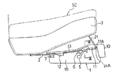
図1はアンダートレイ(1)がシートクッション(SC)の下方に格納している状態を示し、アンダートレイ(1)がワイヤ製のレール(2)に支持され、レール(2)はシートクッション(SC)の底部を構成するパン型フレーム(3)の外底面に前後両端が固定されている。
【0013】
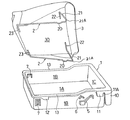
アンダートレイ(1)及びレール(2)(2)は、図6に示すように構成されている。
【0014】
アンダートレイ(1)は合成樹脂で、上部解放状の箱体状に成形され、図中(1A)は底板、(1B)(1B)は側板、(1C)は前板を各々示し、開口縁に沿って外方に直角状に折曲するフランジ部(13)が設けてあり、この左右のフランジ部(13)(13)がレール(2)(2)に支持される。
【0015】
そして、前板(1C)のフランジ部から下方に向けて操作片(10)が延設され、この操作片(10)と前板(1C)との間に指先をさし入れて引くことにより、アンダートレイ(1)がレール(2)(2)から引き出され、また、操作片(10)を上方に持ち上げることにより、格納状態のアンダートレイ(1)のレール(2)に対する係合状態が解除できるように構成されている。
【0016】
アンダートレイ(1)の左右の側板(1B)(1B)側における前側に有するフランジ部(13)(13)には、下向きに突片(11)が延設され、この突片(11)に切欠部(11A)が開口を下向きにして設けてある。
【0017】
また、左右の側板(1B)(1B)側のフランジ部(13)(13)後部には、アンダートレイ(1)の前後動方向に対して後辺側を傾斜状にし、前辺を直交状にした抜止片(12)が下方に向けて突設されている。
【0018】
更に、アンダートレイ(1)の左右の側板(1B)(1B)外側面には、弾性片(5)、ストッパ(6)、ガイド片部(7)が一体成形されている。
【0019】
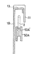
弾性片(5)は、図5に示すように、弾性部(50)と、この弾性部(50)と一体で側板(1B)に一体成形されている固定部(51)とから構成されている。
【0020】
弾性部(50)は、図3に示すように先端部(50A)にレール(2)の段部(20)が収容できるように凹溝(50A′)が形成されている。
【0021】
そして、弾性片(5)の弾性部(50)は、先端部(50A)から基端部(50B)方向に図5に示すように肉厚を徐々に厚く形成して、先端部(50A)に加わる応力集中を防止している。
【0022】
ストッパ(6)は図示するが如く、山形状に左右の側板(1B)外面に一体成形されており、アンダートレイ(1)を上方に持ち上げた際に、図5に示すように、レール(2)に突き当たり、レール(2)に突き当たる弾性片(5)の所定以上の弾性変形を規制して、弾性片(5)の破損を防止している。
【0023】
ガイド片部(7)(7)は、左右の側板(1B)(1B)は、図1に示すように、下方に傾斜する切り起こし状の弾性突起片(70)で、アンダートレイ(1)をレール(2)から引き出す際に、鎖線に示すようにレール(2)によって変形し、レール(2)から容易にアンダートレイ(1)を取り外すことができるように構成されている。
【0024】
レール(2)は剛線で図6に示すように、パン型フレーム(3)の底面に両端が固定され、前側には上向きに折曲する折曲部(21)が設けてあり、この折曲部(21)の下端の角部を係止部(21A)とし、係止部(21A)が図1に示すように、アンダートレイ(1)の格納状態において切欠部(11A)に係合している。
【0025】
従って、切欠部(11A)にレール(2)の係止部(21A)が係合すると、図1に示すように、アンダートレイ(1)の格納状態における前方移動は規制される。
【0026】
そして、このレール(2)の係止部(21A)が切欠部(11A)に係合状態において、前記弾性片(5)に対応する位置には、下向きに凸設する段部(20)がレール(2)に形成され、この段部(20)が弾性片(5)の先端部(50A)内に配置するようにしている。
【0027】
好ましくは、弾性片(5)の弾力によって弾性片がレール(2)の段部(20)に弾接して格納状態のアンダートレイ(1)にガタが生じないようにするのが好ましい。
【0028】
図中(22)(23)は、レール(2)の両端に設けて、フレーム(3)に固定されるレール(2)の端末を示す。
【0029】
次に、アンダートレイ(1)の操作を説明すると、図1のアンダートレイ(1)の格納状態において、アンダートレイ(1)はレール(2)に支持され、前述の如く、係止部(21A)が切欠部(11A)に係合しているため、左右のレール(2)(2)は係合個所で略線径分外方に拡がる。そのため、左右のレール(2)(2)の係止部(21A)の復元力によってアンダートレイ(1)を挟持し、車両の前後方向の振動等によって前方に引き出されることがない。
【0030】
アンダートレイ(1)の操作片(10)を指先で上方に持ち上げると、係止部(21A)に対する切欠部(11A)の係合状態が解除される。そのため、アンダートレイ(1)が引き出せる状態になる。
【0031】
そこで、アンダートレイ(1)を引くと、アンダートレイ(1)はフランジ部(13)がレール(2)(2)に沿って摺動して前方に引き出される。
【0032】
以上のアンダートレイ(1)の引き出し時、或いは、係止部(21)に対する係合状態を解除する際など、アンダートレイ(1)を上方に持ち上げた際、前述の如く、ストッパ(6)がレール(2)に突き当たり、弾性片(5)の弾性変形を一定に規制できるため、弾性片(5)の破損を防止できる。
【0033】
更にアンダートレイ(1)を引くと、図2に示すように、レール(2)の係止部(21A)に抜止片(12)が突き当たるため、アンダートレイ(1)の引き出しは規制され、アンダートレイ(1)の開口部の大部分がシートクッション(SC)の前方に露出する。この状態がアンダートレイ(1)内の物品の出し入れを行う状態である。
【0034】
そして、アンダートレイ(1)をレール(2)から取り外す際には、アンダートレイ(1)を上方に持ち上げると、レール(2)の係止部(21A)から抜止部(12)が外れ、更に、アンダートレイ(1)を引くと、ガイド片部(7)がレール(2)によってアンダートレイ(1)の内方に凹むため、アンダートレイ(1)がレール(2)から容易に取り外すことができる。
【0035】
レール(2)から取り外したアンダートレイ(1)をレール(2)に装着するには、アンダートレイ(1)の左右のフランジ部(13)(13)をレール(2)(2)上に載置して押し込むことにより、図1の格納状態となる。
【0036】
【発明の効果】
本発明によれば、ワイヤ製のレールを使用し、板バネなどの別部品を全く使用しないため、構造が簡単で軽量化を図ることができる。また、レールが弾性を有するため、アンダートレイの取付状態が良好になる。
【図面の簡単な説明】
【図1】本発明に係る構造の側面図である。
【図2】図1の状態からアンダートレイを引き出した状態を示す。
【図3】図1のIIIーIII線断面図である。
【図4】図2のIVーIV線断面図である。
【図5】アンダートレイの弾性片、ストッパの斜視図である。
【図6】分解斜視図である。
【符号の説明】
1 アンダートレイ
2 レール
11 アンダートレイの突片
11A アンダートレイの切欠部
13 フランジ部
21A レールの係止部[0001]
TECHNICAL FIELD OF THE INVENTION
The present invention relates to an under-tray for a vehicle seat such as an automobile seat (seat), and more particularly, to an under-tray mounting structure that is stored below a seat cushion (seat portion) and pulled out and used forward when articles are taken in and out. .
[0002]
A seat with an under tray attached to the bottom side of a conventional seat cushion has a pair of rails with a U-shaped cross section attached to the frame of the seat cushion so that the openings face each other in the front-rear direction, and the under tray can be moved back and forth on this rail (For example, Japanese Utility Model Laid-Open No. 4-134442).
[0003]
The above rail is formed by bending a metal plate into a U-shape, providing a stopper on a part of it, and providing a leaf spring that engages with this stopper on the under tray side to regulate the forward movement of the under tray. I have.
[0004]
[Problems to be solved by the invention]
Therefore, in the conventional product, it is necessary to form the rail with a metal plate having a U-shaped cross section, and to provide an elastic member such as a leaf spring separately from the rail. For this reason, there has been a problem that the seat cannot be reduced in weight, the number of parts is large, and the mounting of the rail to the seat requires a number of steps.
[0005]
Therefore, an object of the present invention is to eliminate such disadvantages of the conventional product.
[0006]
[Means for Solving the Problems]
In order to achieve the above object, the under-tray mounting structure for a vehicle seat according to the present invention is configured such that the rail is formed of a wire, and a locking portion bent upward is provided on a front end side of the under-tray. The protruding piece extending downward from the flange provided in the above is provided with a notch which is notched downward and engages with the locking portion of the rail.
[0007]
Therefore, since the rail is made of wire, the undertray can be engaged with the rail by using the elasticity of the wire to restrict the forward movement of the undertray, and the engaged undertray can be pulled out from the rail. Like that.
[0008]
Preferably, on the left and right side plates of the under tray, a flange portion supported to be movable back and forth on the rail is extended, and an elastic piece for urging the rail upward on the under tray outer surface below the flange portion is referred to as an under tray. By integrally molding, it is possible to prevent backlash of the under tray engaged with the rail.
[0009]
Furthermore, by increasing the thickness of the elastic piece in the direction of the base end portion integrally fixed to the under tray with respect to the tip end portion abutting on the rail, and by making the stress applied to the elastic piece constant, When the elastic piece is integrally formed of a synthetic resin together with the under tray, breakage of the elastic piece due to use can be prevented.
[0010]
Further, by providing a stopper in the vicinity of the elastic piece of the under tray to prevent stress concentration on the elastic piece when the under tray is lifted upward, breakage of the elastic piece can be prevented.
[0011]
In addition, the rear outer wall of the under tray is provided with a guide piece having an inclined surface for pushing and expanding the rail outward when the under tray is pulled out, so that the under tray can be easily pulled out from the rail. Can be removed from the rail.
[0012]
BEST MODE FOR CARRYING OUT THE INVENTION
Hereinafter, an embodiment of the present invention will be described with reference to the drawings.
FIG. 1 shows a state in which the under tray (1) is stored below the seat cushion (SC). The under tray (1) is supported by a wire rail (2), and the rail (2) is connected to the seat cushion (SC). SC), the front and rear ends are fixed to the outer bottom surface of the pan frame (3) constituting the bottom.
[0013]
The under tray (1) and the rails (2) and (2) are configured as shown in FIG.
[0014]
The under tray (1) is made of a synthetic resin and is formed in a box shape with an open top. In the figure, (1A) shows a bottom plate, (1B) and (1B) show side plates, and (1C) shows a front plate. A flange portion (13) that is bent outward at right angles is provided along the right side, and the left and right flange portions (13) and (13) are supported by the rails (2) and (2).
[0015]
An operation piece (10) extends downward from the flange portion of the front plate (1C), and a fingertip is inserted between the operation piece (10) and the front plate (1C) and pulled. , The under tray (1) is pulled out from the rails (2) and (2), and the operating piece (10) is lifted upward, so that the engaged state of the under tray (1) in the stored state with the rail (2) is achieved. It is configured to be released.
[0016]
Projecting pieces (11) extend downward from flange portions (13) and (13) provided on the front side of the left and right side plates (1B) and (1B) of the under tray (1). A notch (11A) is provided with the opening facing downward.
[0017]
The rear side of the flanges (13) and (13) on the left and right side plates (1B) and (1B) has a rear side inclined with respect to the longitudinal movement direction of the under tray (1), and a front side is orthogonal. The retaining piece (12) is formed so as to project downward.
[0018]
Further, elastic pieces (5), stoppers (6) and guide pieces (7) are integrally formed on the outer surfaces of the left and right side plates (1B) and (1B) of the under tray (1).
[0019]
As shown in FIG. 5, the elastic piece (5) includes an elastic part (50) and a fixed part (51) integrally formed with the elastic part (50) and integrally with the side plate (1B). I have.
[0020]
As shown in FIG. 3, the elastic portion (50) has a groove (50A ') formed at its tip (50A) so that the step (20) of the rail (2) can be accommodated.
[0021]
The elastic portion (50) of the elastic piece (5) is formed so as to gradually increase in thickness from the distal end portion (50A) to the proximal end portion (50B) as shown in FIG. Prevents stress concentration applied to the
[0022]
As shown in the figure, the stopper (6) is integrally formed on the outer surfaces of the left and right side plates (1B) in a mountain shape, and when the under tray (1) is lifted upward, as shown in FIG. ), The elastic piece (5) abutting on the rail (2) is restricted from being elastically deformed beyond a predetermined level, thereby preventing the elastic piece (5) from being damaged.
[0023]
As shown in FIG. 1, the guide pieces (7) and (7) have left and right side plates (1 </ b> B) and (1 </ b> B), which are cut-and-raised elastic protrusions (70) that are inclined downward. When the under tray (1) is pulled out from the rail (2), it is deformed by the rail (2) as shown by a chain line so that the under tray (1) can be easily removed from the rail (2).
[0024]
As shown in FIG. 6, the rail (2) is a rigid wire, both ends of which are fixed to the bottom surface of the pan-shaped frame (3), and a bent portion (21) which is bent upward is provided on the front side. The corner at the lower end of the curved portion (21) is defined as a locking portion (21A), and the locking portion (21A) engages with the notch (11A) in the retracted state of the under tray (1) as shown in FIG. are doing.
[0025]
Therefore, when the locking portion (21A) of the rail (2) engages with the notch (11A), as shown in FIG. 1, the forward movement of the under tray (1) in the retracted state is restricted.
[0026]
When the locking portion (21A) of the rail (2) is engaged with the notch (11A), a step (20) projecting downward is provided at a position corresponding to the elastic piece (5). The step (20) is formed on the rail (2) so that the step (20) is arranged in the tip (50A) of the elastic piece (5).
[0027]
Preferably, the elastic piece (5) prevents the elastic piece from resiliently contacting the step (20) of the rail (2) so as to prevent rattling of the stored under tray (1).
[0028]
In the figure, (22) and (23) indicate terminals of the rail (2) which are provided at both ends of the rail (2) and are fixed to the frame (3).
[0029]
Next, the operation of the under-tray (1) will be described. In the storage state of the under-tray (1) in FIG. 1, the under-tray (1) is supported by the rail (2), and as described above, the locking portion (21A) ) Is engaged with the notch portion (11A), so that the left and right rails (2) and (2) expand outward by substantially the wire diameter at the engagement points. Therefore, the under-tray (1) is pinched by the restoring force of the locking portion (21A) of the left and right rails (2) and (2), and is not pulled out forward due to vibration in the front-rear direction of the vehicle.
[0030]
When the operation piece (10) of the under tray (1) is lifted up with a fingertip, the engagement state of the notch (11A) with the locking part (21A) is released. Therefore, the under tray (1) can be pulled out.
[0031]
Therefore, when the under tray (1) is pulled, the flange portion (13) of the under tray (1) slides along the rails (2) and (2) and is pulled out forward.
[0032]
When the under-tray (1) is lifted upward, such as when the under-tray (1) is pulled out or when the under-tray (1) is disengaged from the engagement portion (21), the stopper (6) is moved as described above. Since the elastic piece (5) abuts against the rail (2) and the elastic deformation of the elastic piece (5) can be regulated at a constant level, the elastic piece (5) can be prevented from being damaged.
[0033]
When the under tray (1) is further pulled, as shown in FIG. 2, the retaining piece (12) collides with the locking portion (21A) of the rail (2), so that pulling out of the under tray (1) is restricted, and the under tray (1) is restricted. Most of the opening of the tray (1) is exposed in front of the seat cushion (SC). This state is a state in which articles in the under tray (1) are taken in and out.
[0034]
When removing the under tray (1) from the rail (2), when the under tray (1) is lifted upward, the retaining portion (12) comes off from the locking portion (21A) of the rail (2), and furthermore, When the under tray (1) is pulled, the guide piece (7) is recessed inward of the under tray (1) by the rail (2), so that the under tray (1) can be easily removed from the rail (2). it can.
[0035]
To attach the under tray (1) removed from the rail (2) to the rail (2), the left and right flange portions (13) and (13) of the under tray (1) are mounted on the rails (2) and (2). By pressing and placing, the storage state of FIG. 1 is obtained.
[0036]
【The invention's effect】
ADVANTAGE OF THE INVENTION According to this invention, since a rail made of a wire is used and a separate component such as a leaf spring is not used at all, the structure can be simplified and the weight can be reduced. In addition, since the rail has elasticity, the mounting state of the under tray is improved.
[Brief description of the drawings]
FIG. 1 is a side view of a structure according to the present invention.
FIG. 2 shows a state where an under tray is pulled out from the state of FIG.
FIG. 3 is a sectional view taken along line III-III of FIG. 1;
FIG. 4 is a sectional view taken along the line IV-IV in FIG. 2;
FIG. 5 is a perspective view of an elastic piece and a stopper of the under tray.
FIG. 6 is an exploded perspective view.
[Explanation of symbols]
DESCRIPTION OF SYMBOLS 1 Under
Claims (5)
前記レールをワイヤで形成し、その前端側に上向きに折曲した係止部を設け、前記アンダートレイにおける前側に設けたフランジ部より下方に延設する突片には、下向きに切欠して前記レールの係止部が係合する切欠部を設けてなる車両用シートのアンダートレイ取付構造。In a vehicle seat including a pair of rails having both ends fixed to the bottom of the seat cushion in the front-rear direction and an under tray supported movably back and forth on the rails,
The rail is formed of a wire, a locking portion bent upward is provided on the front end side, and a protruding piece extending below a flange portion provided on the front side of the under tray has a notch downward cut out. An under-tray mounting structure for a vehicle seat provided with a cutout portion with which a locking portion of a rail is engaged.
Priority Applications (1)
| Application Number | Priority Date | Filing Date | Title |
|---|---|---|---|
| JP37694898A JP3583000B2 (en) | 1998-12-28 | 1998-12-28 | Under-tray mounting structure for vehicle seats |
Applications Claiming Priority (1)
| Application Number | Priority Date | Filing Date | Title |
|---|---|---|---|
| JP37694898A JP3583000B2 (en) | 1998-12-28 | 1998-12-28 | Under-tray mounting structure for vehicle seats |
Publications (2)
| Publication Number | Publication Date |
|---|---|
| JP2000198391A JP2000198391A (en) | 2000-07-18 |
| JP3583000B2 true JP3583000B2 (en) | 2004-10-27 |
Family
ID=18508003
Family Applications (1)
| Application Number | Title | Priority Date | Filing Date |
|---|---|---|---|
| JP37694898A Expired - Lifetime JP3583000B2 (en) | 1998-12-28 | 1998-12-28 | Under-tray mounting structure for vehicle seats |
Country Status (1)
| Country | Link |
|---|---|
| JP (1) | JP3583000B2 (en) |
Families Citing this family (2)
| Publication number | Priority date | Publication date | Assignee | Title |
|---|---|---|---|---|
| KR200474366Y1 (en) * | 2012-11-28 | 2014-09-12 | 현대다이모스(주) | Under storage box locking device |
| JP6241221B2 (en) * | 2013-11-19 | 2017-12-06 | 三菱自動車工業株式会社 | Under tray arrangement structure of vehicle seat |
-
1998
- 1998-12-28 JP JP37694898A patent/JP3583000B2/en not_active Expired - Lifetime
Also Published As
| Publication number | Publication date |
|---|---|
| JP2000198391A (en) | 2000-07-18 |
Similar Documents
| Publication | Publication Date | Title |
|---|---|---|
| JP4467746B2 (en) | accessory case | |
| JP4225627B2 (en) | Vehicle drawer device | |
| US5560572A (en) | Instrument panel dovetail slide mounting assembly | |
| JP2002362264A (en) | Mounting structure for vehicle exterior members | |
| JP2007076641A (en) | Anti-rattle tongue plate assembly | |
| JP3583000B2 (en) | Under-tray mounting structure for vehicle seats | |
| JP2979079B2 (en) | Mounting structure for interior materials for automobiles | |
| JP2734999B2 (en) | Suspension rail mechanism | |
| JP3430860B2 (en) | Tray mounting device | |
| JP3789034B2 (en) | Tray cabinet tray retainer | |
| JP3203970B2 (en) | Headrest support | |
| JP4569052B2 (en) | Car body exterior holding clip | |
| JPH0327875Y2 (en) | ||
| JP7737006B2 (en) | Vehicle seats | |
| JP2603526Y2 (en) | Opening / closing slider | |
| JPS6211480Y2 (en) | ||
| JP2605159Y2 (en) | Automotive drawer | |
| JP7406954B2 (en) | Installation device for vehicle interior parts | |
| JP3437105B2 (en) | Ashtray | |
| JP2000108729A (en) | Leg cover of seat slide device | |
| JP2024171529A (en) | Seat operation lever | |
| JP2516228Y2 (en) | Guide device for slide plate for latch | |
| JPH0517404B2 (en) | ||
| JPH094288A (en) | Receiver for door | |
| JPH0244591Y2 (en) |
Legal Events
| Date | Code | Title | Description |
|---|---|---|---|
| A977 | Report on retrieval |
Free format text: JAPANESE INTERMEDIATE CODE: A971007 Effective date: 20040705 |
|
| TRDD | Decision of grant or rejection written | ||
| A01 | Written decision to grant a patent or to grant a registration (utility model) |
Free format text: JAPANESE INTERMEDIATE CODE: A01 Effective date: 20040712 |
|
| A61 | First payment of annual fees (during grant procedure) |
Free format text: JAPANESE INTERMEDIATE CODE: A61 Effective date: 20040727 |
|
| R150 | Certificate of patent or registration of utility model |
Free format text: JAPANESE INTERMEDIATE CODE: R150 |
|
| R250 | Receipt of annual fees |
Free format text: JAPANESE INTERMEDIATE CODE: R250 |
|
| FPAY | Renewal fee payment (event date is renewal date of database) |
Free format text: PAYMENT UNTIL: 20090806 Year of fee payment: 5 |
|
| FPAY | Renewal fee payment (event date is renewal date of database) |
Free format text: PAYMENT UNTIL: 20100806 Year of fee payment: 6 |
|
| FPAY | Renewal fee payment (event date is renewal date of database) |
Free format text: PAYMENT UNTIL: 20110806 Year of fee payment: 7 |
|
| FPAY | Renewal fee payment (event date is renewal date of database) |
Free format text: PAYMENT UNTIL: 20110806 Year of fee payment: 7 |
|
| FPAY | Renewal fee payment (event date is renewal date of database) |
Free format text: PAYMENT UNTIL: 20120806 Year of fee payment: 8 |
|
| FPAY | Renewal fee payment (event date is renewal date of database) |
Free format text: PAYMENT UNTIL: 20130806 Year of fee payment: 9 |
|
| R250 | Receipt of annual fees |
Free format text: JAPANESE INTERMEDIATE CODE: R250 |
|
| R250 | Receipt of annual fees |
Free format text: JAPANESE INTERMEDIATE CODE: R250 |
|
| R250 | Receipt of annual fees |
Free format text: JAPANESE INTERMEDIATE CODE: R250 |
|
| R250 | Receipt of annual fees |
Free format text: JAPANESE INTERMEDIATE CODE: R250 |
|
| R250 | Receipt of annual fees |
Free format text: JAPANESE INTERMEDIATE CODE: R250 |
|
| R250 | Receipt of annual fees |
Free format text: JAPANESE INTERMEDIATE CODE: R250 |
|
| EXPY | Cancellation because of completion of term |