JP3582741B2 - Cooling system - Google Patents
Cooling system Download PDFInfo
- Publication number
- JP3582741B2 JP3582741B2 JP31261794A JP31261794A JP3582741B2 JP 3582741 B2 JP3582741 B2 JP 3582741B2 JP 31261794 A JP31261794 A JP 31261794A JP 31261794 A JP31261794 A JP 31261794A JP 3582741 B2 JP3582741 B2 JP 3582741B2
- Authority
- JP
- Japan
- Prior art keywords
- heat transfer
- support plate
- tube
- cooling device
- transfer tube
- Prior art date
- Legal status (The legal status is an assumption and is not a legal conclusion. Google has not performed a legal analysis and makes no representation as to the accuracy of the status listed.)
- Expired - Fee Related
Links
Images


Classifications
-
- F—MECHANICAL ENGINEERING; LIGHTING; HEATING; WEAPONS; BLASTING
- F28—HEAT EXCHANGE IN GENERAL
- F28F—DETAILS OF HEAT-EXCHANGE AND HEAT-TRANSFER APPARATUS, OF GENERAL APPLICATION
- F28F9/00—Casings; Header boxes; Auxiliary supports for elements; Auxiliary members within casings
- F28F9/02—Header boxes; End plates
- F28F9/0229—Double end plates; Single end plates with hollow spaces
-
- F—MECHANICAL ENGINEERING; LIGHTING; HEATING; WEAPONS; BLASTING
- F28—HEAT EXCHANGE IN GENERAL
- F28D—HEAT-EXCHANGE APPARATUS, NOT PROVIDED FOR IN ANOTHER SUBCLASS, IN WHICH THE HEAT-EXCHANGE MEDIA DO NOT COME INTO DIRECT CONTACT
- F28D7/00—Heat-exchange apparatus having stationary tubular conduit assemblies for both heat-exchange media, the media being in contact with different sides of a conduit wall
- F28D7/02—Heat-exchange apparatus having stationary tubular conduit assemblies for both heat-exchange media, the media being in contact with different sides of a conduit wall the conduits being helically coiled
- F28D7/024—Heat-exchange apparatus having stationary tubular conduit assemblies for both heat-exchange media, the media being in contact with different sides of a conduit wall the conduits being helically coiled the conduits of only one medium being helically coiled tubes, the coils having a cylindrical configuration
-
- F—MECHANICAL ENGINEERING; LIGHTING; HEATING; WEAPONS; BLASTING
- F28—HEAT EXCHANGE IN GENERAL
- F28D—HEAT-EXCHANGE APPARATUS, NOT PROVIDED FOR IN ANOTHER SUBCLASS, IN WHICH THE HEAT-EXCHANGE MEDIA DO NOT COME INTO DIRECT CONTACT
- F28D21/00—Heat-exchange apparatus not covered by any of the groups F28D1/00 - F28D20/00
- F28D2021/0019—Other heat exchangers for particular applications; Heat exchange systems not otherwise provided for
- F28D2021/0075—Other heat exchangers for particular applications; Heat exchange systems not otherwise provided for for syngas or cracked gas cooling systems
Description
【0001】
【産業上の利用分野】
出願人によって供給されている装置のうちで、流体、例えば熱い気体を冷却する装置は市場に大規模に供給されており、例えば石油会社で実際に用いられているもののように、ガス化プロセス等に適用されている。
【0002】
【従来の技術】
このような装置のうちで公知のものが出願人による米国特許公報(及び対応する特許)US−A−4.245.696に記述されている。これらの公知の冷却装置について、実用上、多くの問題が生じており、次に記すものは最も重要な問題になっている。
(1) 冷水流における不具合として、冷却媒体としての水が沸騰して、冷却媒体の能力が著しく低下することがある。
(2) 冷却装置の製造工場或は修理工場への出し入れの間だけでなく、特に冷却水流の中断その他の不具合に伴って生ずる温度の変動下において、比較的厚い金属部品における引張応力(tension) に起因して、更に
(3) 或る種の金属部品については絶対温度値が高い値に達するので、
摩耗及び裂けが発生する。
【0003】
【発明が解決しようとする課題】
本発明は、前記のような、多管式熱交換器としての冷却装置において、前記従来の技術における問題点を解決しようとするものである。
すなわち、本発明が解決しようとする課題は、該冷却装置において、伝熱管の被支持部付近での冷却媒体或いはその蒸気の流通不整を防ぎ、同付近における部品の熱応力上昇を防ぐことである。
【0004】
【課題を解決するための手段】
内部に複数の伝熱管の束が配置され、冷却媒体が該束の周囲を流れる胴と、
前記伝熱管を暖媒体供給用室に開口させる管板と、
該管板から距離をおいて設けられ、前記伝熱管を支持し、かつ、同伝熱管が貫通する支持板と、
該支持板の前記管板に面する側で、同支持板と各伝熱管との間にそれぞれ取付けられ、かつ、前記冷却媒体の通過を許す孔を形成するリング状部材とを備えたことを特徴とする暖媒体の冷却装置を本発明は提供する。
【0005】
伝熱管と支持板との間のリング状の隙間が拡大できるということによって、本発明による冷却装置は前述の問題の一つ以上を解決する。
なぜなら、不必要な蒸気を運び去ることが促進され、前記伝熱管の入口側前部において熱によって生ずる引張応力 (temperature tension)、すなわち前記伝熱管の、前記支持板を通り抜ける箇所に同支持板の裏側(管板に面する側)付近で形成される引張応力が低められるからであり、該前部における熱引張応力(thermal tension) は半分以下に減らされ得る。
前記支持板の後側で溶接することが避けられる、すなわち、伝熱管を更に密に配列することができ、伝熱管(入口側)相互間の、支持されていない領域を小さくできる。なぜなら、前記入口側前部は、より薄く作ることができ、前記入口側前部の熱い側で更に低い絶対温度を可能にするからである。
【0006】
本発明の更なる利点、特徴及び詳細は、本発明の好ましい実施例についての、添付図面を参照した以下の説明に照らして明らかとなろう。
【0007】
【実施例】
本発明による装置の第1の好ましい実施例(図1)は、螺旋状の伝熱管の束を内部に配設した胴1を備えている。この胴1には冷却媒体の出口3が設けられている。伝熱管2は、気体の排出管5に連結された、いくつかの管寄せ(collection headers)4に取り付けられている。伝熱管2は補強された支持板7で支持され、支持板の孔6を貫通して突出している。伝熱管2の端部は管板8に強固に取り付けられ、該管板8は、支持板7に例えば溶接継手9によって強固に溶接されている。同支持板7は、胴1に溶接されている。溶接が容易であるように、伝熱管2は、好ましくは管板8の反対側に管側から溶接される。
【0008】
前記支持板7は更に容器10に強固に取り付けられ、同容器10は暖気体のための室11を内包している。この室11は、暖気体の供給口12を備え、内面が断熱材の厚い層で覆われ、同断熱材も又、容器10が気体圧に対し十分に抵抗できるように役立っている。
【0009】
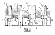
管板8と支持板7との間の領域Sにおいて冷却媒体が充分な量だけ(矢印F)流れるように、管板8に面する方で、孔21を有するリング20が又、伝熱管2と支持板7との間に取り付けられている。
比較的大きい断面を有し、支持板7に強固に溶接された管15を通じて冷却媒体は支持板を通り抜け、管板8に固着した管端部の近くの開口16を通って前記領域Sに送り込まれる。
【0010】
本発明の第二の好ましい実施例(図3及び図4)において、冷却媒体は管板32と支持板33との間の領域に接続管31から導入され、接続排出管34を経て熱交換器35から送り出される。
暖い、或いは熱い気体は接続管36を経て導入され、まっすぐな伝熱管37を経て前記領域及び残った部分を通過し、熱交換器35から導き去られ、接続排出管39から排出される。
前記伝熱管37はリング38によって支持板33の中において、管板32に面する側で強固に保持されており、同リング38は、好ましくは支持板33に溶接されている。
【0011】
請求される権利は、本明細書に記述され、かつ、図面に示された前述の実施例によって定められるものではなく、特許請求の範囲によって定められる。
【0012】
【発明の効果】
本発明は前記「課題を解決するための手段」に記された構成を有するので、支持板における伝熱管貫通部付近に冷却媒体或いはその蒸気が停滞せず、従って冷却装置の冷却能力の低下が防がれ、前記貫通部付近で伝熱管或いは支持板における熱応力が従来のものに比べて著しく低下させられ同装置の寿命がのびるという、すぐれた効果を奏する。
【図面の簡単な説明】
【図1】本発明の第1の好ましい実施例の、一部を破断して断面を示した側面図である。
【図2】図1にIIで示す部分の詳細を示す一部破断側面図である。
【図3】本発明の装置の第二の好ましい実施例を、一部を破断して示す斜視図である。
【図4】図3においてIVで示す一点鎖線に沿ったIV矢視の一部詳細図である。
【符号の説明】
1 胴
2 伝熱管
3 出口
4 管寄せ
5 排出管
6 孔
7 支持板
8 管板
9 溶接接手
10 容器
11 室
12 供給口
15 管
16 開口
20 リング
21 孔
31 接続管
32 管板
33 支持板
34 接続排出管
35 熱交換器
36 接続管
37 伝熱管
38 リング
39 接続排出管
F 矢印
S 領域[0001]
[Industrial applications]
Of the equipment supplied by the Applicant, equipment for cooling fluids, e.g. hot gases, is supplied on a large scale to the market, e.g. gasification processes such as those actually used by oil companies. Has been applied to
[0002]
[Prior art]
Known of such devices are described in Applicant's U.S. Patent Publication (and corresponding patent) U.S. Pat. No. 4,245,696. There are many practical problems with these known cooling devices, and the following are the most important.
(1) As a defect in the cold water flow, water as a cooling medium may boil and the capacity of the cooling medium may be significantly reduced.
(2) Tensile stresses in relatively thick metal parts, not only during the entry and exit of the cooling device into and out of the manufacturing or repair shop, but especially during temperature fluctuations caused by interruption of the cooling water flow and other malfunctions. (3) Since the absolute temperature value of some metal parts reaches a high value,
Wear and tear occur.
[0003]
[Problems to be solved by the invention]
An object of the present invention is to solve the problems in the conventional technique in a cooling device as a multi-tube heat exchanger as described above.
That is, the problem to be solved by the present invention is to prevent the flow of the cooling medium or its vapor in the vicinity of the supported portion of the heat transfer tube from being irregular in the cooling device, and to prevent the thermal stress from increasing in the vicinity of the part. .
[0004]
[Means for Solving the Problems]
Are arranged bundle of a plurality of heat transfer tubes therein, and the trunk coolant Ru flows around the said bundle,
A tubesheet which Ru is opened in the previous SL heat transfer tube warm medium supply chamber,
Provided at a distance from the tube plate, supporting the heat transfer tube, and a Doden'netsukan are you through the support plate,
On the side facing the front Symbol tube plate of the support plate, mounted respectively between the support plate and the heat transfer tube, and, and a ring-shaped member that form a hole that allows the passage of the cooling medium The present invention provides a cooling device for a warming medium characterized by the above-mentioned.
[0005]
The cooling device according to the invention solves one or more of the above-mentioned problems by allowing the ring-shaped gap between the heat transfer tubes and the support plate to be enlarged.
This is because the carryover of unnecessary steam is promoted, and a tensile stress caused by heat at the front side of the inlet side of the heat transfer tube, that is, a portion of the heat transfer tube passing through the support plate at the heat transfer tube. Because the tensile stress formed near the back side (the side facing the tubesheet) is reduced, the thermal tension at the front can be reduced by less than half.
Welding behind the support plate is avoided, i.e. the heat transfer tubes can be arranged more closely and the unsupported area between the heat transfer tubes (entrance side) can be reduced. Because the inlet front can be made thinner, allowing a lower absolute temperature on the hot side of the inlet front.
[0006]
Further advantages, features and details of the present invention will become apparent in view of the following description of a preferred embodiment thereof, made with reference to the accompanying drawings.
[0007]
【Example】
A first preferred embodiment of the device according to the invention (FIG. 1) comprises a shell 1 in which a bundle of helical tubes is arranged. The body 1 is provided with a cooling medium outlet 3. The heat transfer tubes 2 are attached to several collection headers 4 connected to a
[0008]
The support plate 7 is further rigidly attached to a
[0009]
On the side facing the tubesheet 8, the
Through a
[0010]
In the second preferred embodiment of the present invention (FIGS. 3 and 4), the cooling medium is introduced from the connecting pipe 31 into the area between the
The warm or hot gas is introduced via a connecting
The
[0011]
The rights claimed are not defined by the foregoing embodiments described herein and illustrated in the drawings, but by the claims.
[0012]
【The invention's effect】
Since the present invention has the configuration described in the above "Means for Solving the Problems", the cooling medium or its vapor does not stagnate in the vicinity of the heat transfer tube penetrating portion in the support plate, so that the cooling capacity of the cooling device is reduced. Thus, the heat stress in the heat transfer tube or the support plate in the vicinity of the penetrating portion is significantly reduced as compared with the conventional one, and the life of the device is prolonged.
[Brief description of the drawings]
FIG. 1 is a side view of a first preferred embodiment of the present invention, showing a cross-section with a portion cut away.
FIG. 2 is a partially cutaway side view showing details of a portion indicated by II in FIG.
FIG. 3 is a perspective view, partially cut away, of a second preferred embodiment of the device of the present invention.
FIG. 4 is a partially detailed view taken in the direction of the arrow IV along a dashed line indicated by IV in FIG. 3;
[Explanation of symbols]
DESCRIPTION OF SYMBOLS 1 Body 2 Heat transfer tube 3 Outlet 4
Claims (4)
前記伝熱管を暖媒体供給用室に開口させる管板と、
該管板から距離をおいて設けられ、前記伝熱管を支持し、かつ、同伝熱管が貫通する支持板と、
該支持板の前記管板に面する側で、同支持板と各伝熱管との間にそれぞれ取付けられ、かつ、前記冷却媒体の通過を許す孔を形成するリング状部材とを備えたことを特徴とする暖媒体の冷却装置。Are arranged bundle of a plurality of heat transfer tubes therein, and the trunk coolant Ru flows around the said bundle,
A tubesheet which Ru is opened in the previous SL heat transfer tube warm medium supply chamber,
Provided at a distance from the tube plate, supporting the heat transfer tube, and a Doden'netsukan are you through the support plate,
On the side facing the front Symbol tube plate of the support plate, mounted respectively between the support plate and the heat transfer tube, and, and a ring-shaped member that form a hole that allows the passage of the cooling medium A cooling device for a warming medium, characterized in that:
Applications Claiming Priority (2)
| Application Number | Priority Date | Filing Date | Title |
|---|---|---|---|
| NL9302034 | 1993-11-24 | ||
| NL9302034A NL194891C (en) | 1993-11-24 | 1993-11-24 | Cooling device for cooling a warm medium. |
Publications (2)
| Publication Number | Publication Date |
|---|---|
| JPH07260390A JPH07260390A (en) | 1995-10-13 |
| JP3582741B2 true JP3582741B2 (en) | 2004-10-27 |
Family
ID=19863179
Family Applications (1)
| Application Number | Title | Priority Date | Filing Date |
|---|---|---|---|
| JP31261794A Expired - Fee Related JP3582741B2 (en) | 1993-11-24 | 1994-11-22 | Cooling system |
Country Status (4)
| Country | Link |
|---|---|
| US (1) | US5671807A (en) |
| JP (1) | JP3582741B2 (en) |
| DE (1) | DE4439514C2 (en) |
| NL (1) | NL194891C (en) |
Cited By (1)
| Publication number | Priority date | Publication date | Assignee | Title |
|---|---|---|---|---|
| CN104215098A (en) * | 2014-09-16 | 2014-12-17 | 张家港市华菱化工机械有限公司 | Heat exchanger for polypropylene chemical process |
Families Citing this family (13)
| Publication number | Priority date | Publication date | Assignee | Title |
|---|---|---|---|---|
| US5979543A (en) * | 1995-10-26 | 1999-11-09 | Graham; Robert G. | Low to medium pressure high temperature all-ceramic air to air indirect heat exchangers with novel ball joints and assemblies |
| FR2785980B1 (en) * | 1998-11-16 | 2001-11-30 | Valeo Thermique Moteur Sa | HEAT EXCHANGER WITH TUBE BEAM CONTAINED IN A CYLINDRICAL HOUSING |
| DE10243522A1 (en) * | 2002-09-19 | 2004-04-01 | Modine Manufacturing Co., Racine | Plate heat exchangers |
| DE602004004908T2 (en) * | 2003-08-06 | 2007-10-31 | Shell Internationale Research Maatschappij B.V. | DEVICE AND METHOD FOR COOLING HOT GAS |
| ATE440255T1 (en) * | 2004-05-25 | 2009-09-15 | Shell Int Research | DEVICE FOR COOLING HOT GAS |
| CA2648683C (en) * | 2006-04-12 | 2014-11-18 | Shell Internationale Research Maatschappij B.V. | Apparatus and process for cooling hot gas |
| ES2342209T3 (en) | 2007-12-11 | 2010-07-02 | Alfa Laval Spiral Snc | SPIRAL HEAT EXCHANGER. |
| CA2687018A1 (en) * | 2008-12-08 | 2010-06-08 | Shell Internationale Research Maatschappij B.V. | Apparatus |
| US8672021B2 (en) * | 2010-02-12 | 2014-03-18 | Alfred N. Montestruc, III | Simplified flow shell and tube type heat exchanger for transfer line exchangers and like applications |
| CN104061814A (en) * | 2014-07-04 | 2014-09-24 | 大连海新工程技术有限公司 | Multi-layer S-shaped coiled tube type flash heater |
| CN105806105A (en) * | 2014-12-31 | 2016-07-27 | 天津华赛尔传热设备有限公司 | Plate heat exchanger |
| CN104990432A (en) * | 2015-07-31 | 2015-10-21 | 四川金锋建设有限公司 | Application method of heat exchanger tube bundle |
| CN106767040B (en) * | 2016-12-20 | 2019-02-15 | 深圳市迅凌科技有限公司 | Column loop type water cooling heat exchanger |
Family Cites Families (10)
| Publication number | Priority date | Publication date | Assignee | Title |
|---|---|---|---|---|
| US2365515A (en) * | 1943-06-10 | 1944-12-19 | Westinghouse Electric & Mfg Co | Water cooler |
| US3356135A (en) * | 1964-12-24 | 1967-12-05 | Robert K Sayre | Once-through steam generator with means to provide saturated feed water |
| DE1953628B2 (en) * | 1969-10-24 | 1973-05-24 | L & C Steinmuller GmbH, 5270 Gum mersbach | PIPE HEAT EXCHANGER |
| FR2243386B1 (en) * | 1973-09-07 | 1976-11-19 | Commissariat Energie Atomique | |
| JPS535453A (en) * | 1976-07-05 | 1978-01-19 | Mitsubishi Heavy Ind Ltd | Multi-pipe heat exchanger |
| DE2818892C2 (en) * | 1978-04-28 | 1988-12-22 | Bronswerk B.V., Amersfoort | Heat exchanger for cooling down hot gases |
| US4279293A (en) * | 1979-06-18 | 1981-07-21 | Westinghouse Electric Corp. | High temperature heat exchanger having porous tube sheet portions |
| US4537249A (en) * | 1981-02-02 | 1985-08-27 | The United States Of America As Represented By The United States Department Of Energy | Heat flux limiting sleeves |
| US4445463A (en) * | 1983-04-06 | 1984-05-01 | Syngas Company | Waste heat boiler |
| US4641706A (en) * | 1984-11-05 | 1987-02-10 | Chicago Bridge & Iron Company | Vertical shell and tube heat exchanger with spacer or clip to form uniform thickness falling films on exterior surfaces of tubes |
-
1993
- 1993-11-24 NL NL9302034A patent/NL194891C/en not_active IP Right Cessation
-
1994
- 1994-11-04 DE DE4439514A patent/DE4439514C2/en not_active Expired - Lifetime
- 1994-11-18 US US08/342,413 patent/US5671807A/en not_active Expired - Fee Related
- 1994-11-22 JP JP31261794A patent/JP3582741B2/en not_active Expired - Fee Related
Cited By (1)
| Publication number | Priority date | Publication date | Assignee | Title |
|---|---|---|---|---|
| CN104215098A (en) * | 2014-09-16 | 2014-12-17 | 张家港市华菱化工机械有限公司 | Heat exchanger for polypropylene chemical process |
Also Published As
| Publication number | Publication date |
|---|---|
| DE4439514C2 (en) | 1998-08-27 |
| NL194891B (en) | 2003-02-03 |
| JPH07260390A (en) | 1995-10-13 |
| DE4439514A1 (en) | 1995-06-01 |
| US5671807A (en) | 1997-09-30 |
| NL194891C (en) | 2003-06-04 |
| NL9302034A (en) | 1995-06-16 |
Similar Documents
| Publication | Publication Date | Title |
|---|---|---|
| JP3582741B2 (en) | Cooling system | |
| US4401153A (en) | Heat exchanger incorporating nitriding-resistant material | |
| US20170074593A1 (en) | Tube bundle heat exchanger | |
| JP3129727B2 (en) | Tube bundle heat exchanger | |
| JPS6042843B2 (en) | Waste heat boiler | |
| CN101166937A (en) | Discrete double heat exchange type hot water boiler | |
| JPH0359397A (en) | Tubular heat exchanger with fin | |
| CN108474588A (en) | It is provided with the condensate and heat exchanger of heat-exchange device | |
| TW445366B (en) | Assembly body of heat exchange coils | |
| JPH09152283A (en) | Heat exchanger | |
| US6811756B2 (en) | Exhaust gas cooler | |
| JPH0456238B2 (en) | ||
| US4867234A (en) | Heat exchanger | |
| JPS6038334B2 (en) | Equipment for generating steam in an ammonia synthesis plant | |
| EP0074434B1 (en) | Heat exchanger and use thereof | |
| JPH06201290A (en) | Heat exchanger used for cooling reaction gas at high temperature | |
| JPS5941110B2 (en) | Heat exchanger with double tube members | |
| JP2971685B2 (en) | Heat exchanger and method of manufacturing the same | |
| JP3361010B2 (en) | Multi-tube heat exchanger | |
| JPH0325038Y2 (en) | ||
| JP3998073B2 (en) | Heat exchanger | |
| US20200263929A1 (en) | Fire tube | |
| JP2694894B2 (en) | Heat exchanger | |
| JP4485253B2 (en) | Cast iron sectional pressureless hot water heater | |
| JP3054565B2 (en) | Hydrogen gas discharge device |
Legal Events
| Date | Code | Title | Description |
|---|---|---|---|
| A977 | Report on retrieval |
Free format text: JAPANESE INTERMEDIATE CODE: A971007 Effective date: 20040622 |
|
| TRDD | Decision of grant or rejection written | ||
| A01 | Written decision to grant a patent or to grant a registration (utility model) |
Free format text: JAPANESE INTERMEDIATE CODE: A01 Effective date: 20040625 |
|
| A61 | First payment of annual fees (during grant procedure) |
Free format text: JAPANESE INTERMEDIATE CODE: A61 Effective date: 20040723 |
|
| R150 | Certificate of patent or registration of utility model |
Free format text: JAPANESE INTERMEDIATE CODE: R150 |
|
| LAPS | Cancellation because of no payment of annual fees |