JP3580404B2 - ATM-M bus system maintenance operation method and ID reallocation method - Google Patents
ATM-M bus system maintenance operation method and ID reallocation method Download PDFInfo
- Publication number
- JP3580404B2 JP3580404B2 JP23199098A JP23199098A JP3580404B2 JP 3580404 B2 JP3580404 B2 JP 3580404B2 JP 23199098 A JP23199098 A JP 23199098A JP 23199098 A JP23199098 A JP 23199098A JP 3580404 B2 JP3580404 B2 JP 3580404B2
- Authority
- JP
- Japan
- Prior art keywords
- bus
- atm
- cell
- branching device
- branching
- Prior art date
- Legal status (The legal status is an assumption and is not a legal conclusion. Google has not performed a legal analysis and makes no representation as to the accuracy of the status listed.)
- Expired - Fee Related
Links
Images


Description
【0001】
【発明の属する技術分野】
本発明は、ATM(Asynchronous Transfer Mode:非同期転送モード)交換方式に適用するバス方式に関し、詳細には、ATM交換機に収容される端末間でデータ交換を行うマルチメディアバス(Mバス)方式に関する。
【0002】
【従来の技術】
本出願人は、特願平9−10231号(特開平10―210045号公報)の出願において、ATMスイッチとATM155Mbpsインタフェースを有する主装置と、該主装置に直列に収容される複数の分岐装置とからなり、該分岐装置は端末装置を収容するとともに前記ATM155Mbpsインタフェースの上りバスと下りバスに接続され、該バスの下りバスの終端が折り返されて上りバスとされている「ATM−Uバス方式」と呼ぶバス方式を提案している。
このバス方式に用いるUバス主装置は、音声/画像/データなどを全てATMセル化し、155Mbpsポートに独自のATMバスインターフェース(I/F)を有し、その配下に複数の標準ATM端末を収容するとともに、高速ATM端末を直接そのポートに収容することで、一元的に交換処理を行う小規模オフィス対応のATM装置である。
【0003】
このUバス方式を採用した小規模事業所用のUバス主装置の構成を図12に示す。Uバス主装置1は、ATM交換装置としての機能を有しており、ATMスイッチ(ATM−SW)11と、155MbpsのU−GFC制御付ATMインタフェース12’とを有して構成され、さらに図示を省略した100MbpsのLANインタフェースと、既存のWANインタフェースと、制御部と、蓄電池を具備した電源ユニットを有して構成されている。
【0004】
ATMスイッチ(ATM−SW)11は、通常のATMスイッチと同様であり、本実施例では、155Mbpsのポート8個を有している。
【0005】
Uバス主装置(ATM交換機)1の155MbpsのATMインタフェース12’は、Uバス2およびATM155Mbps端末ならびにATM155Mbps回線を直接収容できるインタフェースパッケージであり、ATMセルのヘッダ内に設けられたGFC部分を使用したU−GFC制御機能を有している。
ATMインタフェース12’は、ATMセル中のGFCとバーチャルパス(VP)とバーチャルチャネル(VC)を変換するとともにスイッチングのためのタグを付与するVP/VC変換手段と、ATM155Mbps仕様のユーザーネットワークインタフェースである155MbpsATMユニットと、光/電気変換インタフェースと、VP/VC変換のための参照テーブル(GFCを含む)を格納したSRAMと、送受信セルのU−GFC制御を行うU−GFC制御ユニットとから構成され、例えば、カード状のパッケージに形成される。
U−GFC制御ユニットは、下りバスに送り出すATMセル(下りセル)IDを蓄積する下りセル用FIFOメモリと、上りバスから受信した上りセルIDを記録する上りセル用FIFOメモリと、下りセル用FIFOメモリに蓄積された下りセルIDと上りセル用FIFOメモリに記録された上りセルIDとの一致をみる比較手段を有している。
【0006】
ATM155Mbpsインタフェース12’には、Uバスと呼ぶATMバス2およびATM端末、ATM−PNNIを介して他のATM交換機、ATM−UNIを介してATM−WANがそれぞれ接続される。
また、LANインタフェースには、100Mbpsの既存のLAN網が接続される。
さらに、既存WANインタフェースには、ISDN回線またはアナログ回線、専用線、OCN等が接続される。
【0007】
制御部は、Uバス主装置1の交換制御およびパッケージ制御ならびにネットワーク管理の制御を行う。
【0008】
Uバス2は、ATM端末を接続することができるバスであり、U−GFC制御付きのATM155Mbpsインタフェース12’に収容される。Uバス2には、分岐装置3−1,3−2,3−nを介して、複数のマルチメディア端末や画像端末などの例えば、多機能ボタン電話機である25MbpsのATMキーテレホン(ATM−KT)51、155MbpsのATM端末52、3.1KHzオーディオ(64Kbps)のアナログ電話機53、ISDN端末54、25MbpsのATM端末55が分岐装置3を介して接続され、アナログ電話機53、ISDN端末54などは既存端末用分岐装置3−3を介して接続され、さらに155Mbpsのサーバ/コンピュータなどのATM端末52が接続される。
【0009】
例えば、これらの端末は、155MbpsのUバス2のトラヒック容量を考慮して複数接続される。
【0010】
ATMキーテレホンは、電話機内部にCLADを有しており、ATM25bpsインタフェースでUバス2に接続される。
【0011】
上述のように、このATM−Uバス方式は、各分岐装置に識別子を付与し、主装置から送り出すATMセルのヘッダのGFC(一般的フロー制御)フィールドにATMセルの宛先の分岐装置の識別子を付与して送り出す方式である。
さらに、このATM−Uバス方式は、分岐装置が受信した自己宛のセルを分岐して端末装置に送るようにし、分岐装置に収容された端末装置からの送信データがないとき、分岐装置で受信した自己宛のセルの識別子を削除して空きセルとして下流ノードへ送り出し、分岐装置に収容された端末装置からの送信データがあるとき、分岐装置で受信した自己宛のセルまたは空きセルに送信データを乗せて送り出すようにしている。
【0012】
また、このATM−Uバス方式は、分岐装置に端末装置からの送信データを一時格納する複数の送信バッファを設け、送信バッファの値が所定の値に達したときに該分岐装置宛のセルを“SOS”セルとして主装置に送り返し、主装置は“SOS”セルを受けたときに強制的に共用チャネル以外の下りセルに前記分岐装置の識別子を付与した予約空きセルを送出するようにしている。
【0013】
ATM−Uバス方式に用いる分岐装置は、ATM−Uバスに接続され、上流側インタフェースと、下流側インタフェースと、端末装置への入出力インタフェースとを有し、受信したATMセルのヘッダに付与された識別子を抽出して自己宛のセルを分岐する機能と、セル分解・組立(CLAD)機能と、自己宛のセルまたは空きセルに送信データを乗せるセル挿入機能を有するバス制御手段を備えている。
【0014】
ATM−Uバス方式に用いるATM155Mbpsインタフェースは、ATMバスが接続され、下りバスに送出するATMセルのGFCに付した識別子を蓄積するFIFOメモリと、上りバスで受信したATMセルのGFCに付した識別子を蓄積するFIFOメモリと、下りバスに送出するATMセルのGFCに付した識別子と上りバスで受信したATMセルのGFCに付した識別子とを比較する手段とを有しており、下りバスに送出するATMセルのGFCに付した識別子の蓄積がなく、上りバスで受信したATMセルのGFCに付した識別子が記憶されたときに端末装置を指定した空きセルを下りバスに割り当てる機能を有している。
【0015】
このATM−Uバス方式は、標準方式ATM−スイッチ(SW)を用いて実現することができ、主装置の各155Mbpsインタフェースでは、上記“M−GFCフロー制御”を無視するか無効とすることによって、標準のATM155Mbpsポートとしても使用でき、各分岐装置の端末装置は公平かつ効率的に送信することが可能となり、かつ、セルの最大遅延等の特性を最大限保証することができる。
音声の様な既存端末装置などの対称サービスは、その端末装置の受信セルだけによって送信の保証が可能となる.
サーバアクセス、インタネットアクセス等の非対称サービスに対して、U−GFCフロー制御および“SOS”セルによってセルの有効利用が可能となる.
Uバス上の端末装置は“マルチキャスト”通信が可能である.
分岐装置の配下に端末装置をマルチポイントに接続することが可能となる.
CLAD付き分岐装置を接続することによって、既存端末装置を直接収容することが可能となる.
Uバス方式のソフト処理は、初期設定、OAM管理、Uバス管理の他にはほとんど必要ないので、Uバス方式を容易に実現することができる.
ハードウェアは、ATM155Mbpsインタフェースを設けるだけであり、UTOPIAバス制御、セル挿入・分岐、およびバッファ処理が増えるだけであるので、Uバス方式は容易に実現することができる.
という優れた効果を奏する方式である。
【0016】
上記ATM−Uバス方式においては、バスに接続された分岐装置を制御するには、各分岐装置に固有の識別子を割り振ることが必要となるが、この識別子の割り当ては例えばハード的なスイッチを用いて手動で設定していた。
このように手動による識別子割り当ては、識別子の割り当て誤りを生じたり、Uバスに接続されている分岐装置の管理をそれぞれ個別にする必要がある。
【0017】
【発明が解決しようとする課題】
本発明は、上記ATM−Uバス(以下、本明細書においては、Mバスという)システムにおいて、Mバスに障害が発生した場合に上位側の分岐装置の動作を確保する保守運用方法を提供すること、および、Mバスに発生した障害が復旧した場合や、Mバスに収容された分岐装置がプログラムを立ち上げたときに、上流側の分岐装置の動作を妨げることなく下流側の分岐装置にIDを再び割り当てる方法を提供することを課題とする。
【0018】
【課題を解決するための手段】
上記課題を解決するために、本発明は、ATM交換機に収容されたMバスインタフェースユニットと、両端が前記Mバスインタフェースユニットに収容され最遠端で折り返された下りバスおよび上りバスからなるMバスと、該Mバスの下りバスと上りバスにそれぞれに直列に接続された複数の分岐装置からなるATM−Mバスシステムの保守運用方法において、分岐装置が障害を常時監視し、障害の発生点より上位の分岐装置にループバックを形成するようにした。
【0019】
本発明は、上記ATM−Mバスシステムの保守運用方法において、下りバス上に入力信号断(LOS)もしくはフレーム同期はずれ(LOF)を検出した分岐装置は、自己のIDを“0”クリアし、下位にはマルチキャストセルのIDリセット要求を送出するとともに上位に遠端受信故障(FERF)信号を送出し、遠端受信故障(FERF)信号を受信した上位分岐装置は、自己の分岐装置内にループバックを設定し、下位分岐装置宛セルを受信端で全て廃棄して下位側を切り離すとともに、Mバスインタフェースに対してループバック実施通知(LBA)を送出するようにした。
【0020】
また、本発明は、上記ATM−Mバスシステムの保守運用方法において、上りバス上に入力信号断(LOS)もしくはフレーム同期はずれ(LOF)を検出した分岐装置は、下位に警報表示信号(AIS)を送出し、自己の分岐装置内にループバックを設定し、下位分岐装置宛セルを受信端で全て廃棄して下位側を切り離すとともに、Mバスインタフェースに対してループバック実施通知(LBA)を送出するようにした。
【0021】
さらに、本発明は、上記ATM−Mバスシステムの保守運用方法において、下りバス上に入力信号断(LOS)もしくはフレーム同期はずれ(LOF)を検出した最上位の分岐装置は、自己のIDを“0”クリアし下位にはマルチキャストセルのIDリセット要求を送出するとともにMバスインタフェースユニットに遠端受信故障(FERF)信号を送出し、遠端受信故障(FERF)信号を受信したMバスインタフェースユニットは、Mバス主装置の中央制御ユニット(CCU)に対し制御セルを用いてループバックしたと等価の情報を通知するようにした。
【0022】
本発明は、上記ATM−Mバスシステムの保守運用方法において、上りバス上に入力信号断(LOS)もしくはフレーム同期はずれ(LOF)を検出したMバスインタフェースユニットは、下りバスに警報表示信号(AIS)を送出するとともにMバス主装置の中央制御ユニット(CCU)に対し制御セルを用いてループバックしたと等価の情報を通知するようにした。
【0023】
上記課題を解決するために、本発明は、ATM交換機に収容されたMバスインタフェースユニットと、両端が前記Mバスインタフェースユニットに収容され最遠端で折り返された下りバスおよび上りバスからなるMバスと、該Mバスに直列に接続された複数の分岐装置からなるATM−Mバスシステムであって、Mバスに障害が発生したときに障害発生点より上位側の分岐装置にループバックを構成し上位側の通信を確保するようにしたATM−Mバスシステムにおける障害復旧時に、下位の分岐装置に対して再びIDを割り当てるATM−MバスのID再割当方法において、分岐装置が上位側障害を常時監視し、上位側障害を検出した分岐装置が自己のIDを“0”にするとともに、下位の分岐装置に対してマルチキャスト方式によってIDリセット要求を送出し、IDリセット要求を受信した下位の分岐装置は自己のIDをリセットして“0”にし、定期的にID要求をMバスインタフェースユニットに対して送信するようにした。
【0024】
さらに、本発明は、上記ATM−MバスシステムID再割当方法において、Mバスインタフェースユニットは、分岐装置からのID要求を受信すると、ID割当要求の一時休止を要求するID割当確認通知を送出し、次いで、ID番号を搭載したID割当確認要求を若いID番号から追い番で順次下りバス上に送出し、ID割当確認応答がなく送出したID番号のID割当確認要求を上りバスで受信したときに、当該ID番号のID割当要求を下りバスに送出するようにした。
【0025】
また、本発明は、上記ATM−MバスシステムのID再割当方法において、下りバス上にID割当要求を受信した自己のIDが“0”の分岐装置が、当該IDを取り込み下流に空きセルを転送するとともに、Mバスユニットに対してID割当応答を送出するようにした。
【0026】
【発明の実施の形態】
以下、本発明にかかるATM−Mバス方式の識別番号割当方法の実施の形態を図を用いて説明する。
【0027】
本発明は、上記した先願にかかるATM−Uバス方式に準じた方式を採用しており、マルチメディアバス(以下、Mバスという)と、Mバスインタフェースユニット(以下、MBUという)と、端末インターフェース分岐装置(以下、単に分岐装置という)で構成されるATM−Mバス方式に関する。
本発明にかかるATM−Mバス方式に用いる分岐装置は、ATM25Mbps端末装置やATM155Mbps端末装置などのマルチメディアに対応することができる分岐装置であり、ATMボタン電話機等の25MbpsATM端末装置および155Mbps専用ATM端末装置ならびに汎用ATM端末装置などを収容する。MBUは、分岐装置との間でATMセルを送受信する。
【0028】
本発明にかかるATM−Mバス方式の概要を図1を用いて説明する。
ATM−Mバス方式は、Mバス主装置1と、155MbpsのMバス2と、該Mバスに直列に接続された複数の分岐装置3とから構成され、分岐装置3には25MbpsのATM−KT51、155MbpsのATM端末装置52,25MbpsのATM端末装置55などが接続線6を介して収容される。
【0029】
Mバス主装置1は、ATM交換機としての機能を有しており、ATMスイッチ(ATM−SW)11と、Mバス2をATMスイッチに収容させるゲートウェイとして働くMBU12と、N−ISDN基本インタフェースユニット15と、中央制御装置(以下、CCUという)19とを有して構成される。
さらに、Mバス主装置1は、25Mbps端末インタフェースユニット13、LANユニット14、25Mbpsノード間インタフェースユニット(25MNU)16、三者会議ユニット(CNFU)17、音声通話タイプ変換ユニット(VTU)18などを有することができる。
【0030】
Mバス2は、MBU12に接続された下りバスと上りバスから構成され、複数の分岐装置3がシリーズに接続される。下りバスは、終端に設けた折返部21で折り返されて上りバスとされている。
Mバス2は、マルチモード光ファイバ(以下、MMFという)または100Ωの銅線ケーブル(以下、UTPという)を用いて155MbpsのATMバスとして構成される。
MBU12から最遠端にある分岐装置3−nでは、Mバス2の下りバスと上りバスは、折返部21によってU字接続されている。MBU12から下りバスに送出されたセルは、折返部21で折り返されて上りバスに乗ってMBU12へ戻ってくる。
【0031】
分岐装置3は、MMFからなるMバス2の下りバスと上りバスに接続され、下りバスで受信したATMセルを下流に中継する機能と、上りバスで受信したATMセルを上流に中継する機能と、下りバスで受信した自己宛のATMセルを取り込む機能と、端末装置からのデータを空きセルに乗せて送り出す機能を有している。
また、分岐装置3は、シグナリングによる該当ユーザセルのVPI/VCIの取得および管理機能、該当ユーザセルのGFC制御機能、Mバスおよび端末インタフェースポートの障害監視機能を有している。
さらに、分岐装置3は、155Mbps端末インタフェースポートを有するか、25Mbps端末インタフェースポートを複数有している。
各分岐装置3には、25MbpsのATMボタン電話機(ATM−KT)51、25MbpsのATM標準端末装置55、155MbpsのATM標準端末装置52、Q2931をサポートする汎用ATM端末装置等が収容される。
分岐装置3は、最大14台がシリーズに接続される。
【0032】
分岐装置3は、155Mbpsの端末インタフェースポートを有する分岐装置155Mと25Mbpsの端末インタフェースポートを有する分岐装置25Mとがある。
分岐装置155Mは、MBU12が提供するMバス2に155MbpsATM端末装置を1ポート接続するための分岐装置である。
分岐装置25Mは、MBU12が提供するMバス2に25MbpsのATMボタン電話機またはATM標準端末装置を1ポート接続する分岐装置である。
分岐装置155Mと分岐装置25Mは、一つのMバス上に混在して最大14台まで収容することができる。
【0033】
分岐装置155Mのブロック構成を図2を用いて説明する。
分岐装置3は、Mバス2および155MbpsATM端末に接続される3台の光/電気変換用インタフェース30と、3台の155MbpsATM UNI LSI31−1,31−2,31−3と、セル分岐挿入制御部を構成するプログラマブルゲートアレイ(Programable Logic Device,以下、PLDという)32と、PLD制御用ROM33と、F−ROM34と、RAM35と、CPU36と、LED表示部37と、AC/DCコンバータ38と、リセット回路39とを有して構成される。
光/電気変換用インタフェース30は、Mバス2がUTPで構成されるときには、パルストランスで構成される。
【0034】
分岐装置25Mのブロック構成を図3を用いて説明する。
分岐装置3は、Mバス2に接続される2台の光/電気変換用インタフェース30と、2台の155MbpsATM UNI LSI31−1,31−2と、1台の25MbpsATM UNI LSI31−3と、PLD32と、PLD制御用ROM33と、F−ROM34と、RAM35と、CPU36と、LED表示部37と、AC/DCコンバータ38と、リセット回路39と、25MbpsATM端末に接続されるパルストランス30PTとを有して構成される。
光/電気変換用インタフェース30は、Mバス2がUTPで構成されるときには、パルストランスで構成される。
【0035】
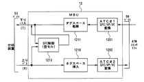
Mバスインタフェースユニット(MBU)12の、構成を図4のブロック図を用いて説明する。
MBU12は、2台のGFC/VP/VC変換手段(ATC)120と、PLD121と、155MbpsATM UNI LSI122と、光/電気変換用インタフェース123と、F−ROM124と、S−RAM125と、CPU126と、LED表示部127と、PLL回路128とを有して構成される。
【0036】
PLD121は、タグ削除部1211と、2台のM−GFC制御部1212,と、2台のAAL5処理部1213と、リセット回路1214と、OAM回路1215と、タグ挿入部1216とを有して構成される。
【0037】
ATMセルのGFC(4bit)は、NNI(Network Node Interface)には規定がなくエンド・エンド(End−to−End)の機能としては使用されず、UNIの部分にのみ使用されるフィールドである。
本発明のMバス2では、複数の分岐装置3をシリーズ接続し、分岐装置間(Mバス区間)でのみ、ATMセルのヘッダのGFCの4bitに各分岐装置の識別番号(以下、IDという)を搭載し、GFCに搭載したIDでルーティングを行う。
【0038】
ATM−Mバス方式における、GFC制御プロトコルを本明細書ではM−GFC制御プロトコルと定義する。
M−GFC制御プロトコルは、MBU12と分岐装置3のハードウエア(一部ソフト介在)で実現するバス制御プロトコルである。M−GFCフロー制御を実現する上での前提条件を以下に示す。
MBU12から送信するバスを下りバス、最遠端の分岐装置3−nで折り返されてMBU12へ向かうバスを上りバスという。
各分岐装置3の識別子IDは、後述するMBU12からの識別子自動割当て処理によって決定される。
分岐装置3によるバス上のATMセルの送信および受信は、受信セルは下りバスからのみ取り込み、送信セルは下りバスまたは上りバス上のどちらの空きセルにもセットすることができる。ただし、送信は、上りバスへの送出を優先とする。
【0039】
Mバスで管理されるセル種別は、GFC/VP/VCにより定義される。その定義の内容を表1に示す。
【0040】
【表1】
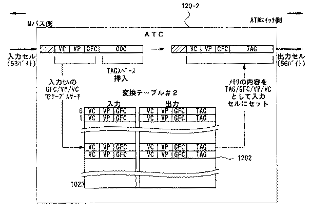
表1に示すように、GFC/VP/VCが“0/0/0”とされたATMセルは、空きセルであり、ペイロードは全て“6Ah”の繰返しとなる。
GFC/VP/VCが“0/VPI/VCI”とされたセルは、分岐装置からのSOSセルであり、データセルのGFCを“0”にして作られる。
GFC/VP/VCが“ID/0/0”とされたセルは、IDによって分岐装置が指定された予約空きセルであり、MBUから下りバスに送出される。
GFC/VP/VCが“ID/VPI/VCI”とされたセルは、IDによって分岐装置が指定された送信または受信データセルである。
GFC/VP/VCが“ID/VPI/VCI”とされたセルは、マルチバスインタフェースユニットMBUと分岐装置間の制御セルであり、制御専用のVPI/VCI値が用いられる。
GFC/VP/VCが“15/VPI/VCI”とされたセルは、分岐装置からのマルチキャスト用送信および受信データセルである。
GFC/VP/VCが“ID/0/5”とされたセルは、IDによって分岐装置が指定された送信および受信ポイント−ポイントシグナリングセルである。
GFC/VP/VCが“ID/VPI/3”とされたセルは、障害時の専用セルで、IDによって分岐装置が指定された送信または受信ポイント−ポイント対応VP用OAMセルであり、セグメントに対応している。
GFC/VP/VCが“ID/VPI/4”とされたセルは、障害時の専用セルで、IDによって分岐装置が指定された送信または受信ポイント−ポイント対応VP用OAMセルであり、エンド−エンドに対応している。
【0042】
MBU−ATMスイッチ間および分岐装置−端末装置間を流れるセルのGFCは“0”で構成される。
【0043】
次いで、MBUプロトコルについて説明する。
MBU12には、上りルーティングテーブルおよび下りルーティングテーブルからなる変換テーブルが形成される。上りルーティングテーブルは、バス上の通信中の呼のGFC(ID)/VP/VCをATMスイッチ管理用GFC/VP/VCに相互に変換するテーブルである。下りルーティングテーブルは、ATMスイッチ管理用GFC/VP/VCをバス上の通信中の呼のGFC(ID)/VP/VCに相互変換するテーブルである。
これらのルーティングテーブルは、Mバス上の最大コネクション数で、CCUによって決定されたデータを基に管理される。
これらのルーティングテーブルは、ATMスイッチ交換用のスイッチングタグの挿抜も行う。
【0044】
ATC120におけるルーティングテーブルを用いた基本的な変換法則および変換方法を表2および図5を用いて説明する。
表2(A)は、シグナリングセルおよびOAMセル用の共用チャネル上の変換であり、表2(B)は、ユーザセル用のユーザチャネル上の変換であり、表2(C)は、マルチキャストセル用のユーザチャネル上の変換である。
【0045】
【表2】
シグナリングセルおよびOAMセルを対象とした共用チャネルでは、上り方向では、GFC/VP/VCについて、Mバス上のセルの“ID番号/0(固定)/VCI”を、MBU−ATMスイッチ間のセルの“0(固定)/VPI(CCU管理用)/VCI(CCU管理用)”に変換する。一方、下りセルでは、GFC/VP/VCについて、ATMスイッチ−MBU間のセルの“0(固定)/VPI(CCU管理用)/VCI(CCU管理用)”をMバス上のセルの“ID番号/0(固定)/VCI”に変換する。
【0047】
ユーザセルを対象としたユーザチャネルでは、上り方向では、GFC/VP/VCについて、Mバス上のセルの“ID番号/VPI/VCI”を、MBU−ATMスイッチ間のセルの“0(固定)/VPI(CCU管理用)/VCI(CCU管理用)”に変換する。一方、下りセルでは、GFC/VP/VCについて、ATMスイッチ−MBU間のセルの“0(固定)/VPI(CCU管理用)/VCI(CCU管理用)”をMバス上のセルの“ID番号/VPI/VCI”に変換する。
【0048】
マルチキャスト用セルを対象としたユーザチャネルでは、上り方向では、なんら変換作業を行わず、下りセルでは、GFC/VP/VCについて、ATMスイッチ−MBU間のセルの“0(固定)/VPI(CCU管理用)/VCI(CCU管理用)”をMバス上のセルの“15/VPI/VCI”に変換する。
【0049】
MBU12に設けたGFC/VP/VC変換手段(ATC)120の働きを、図5を用いて説明する。ここでは、上りバスから入力された53バイトのATMセルをATMスイッチ11へ向けて送出する56バイトのATMセルに変換するATC120−2を例にしている。
ATC120−2では、Mバスから入力された53バイトのATMセルから、GFC/VP/VCを読み出すとともにスイッチングタグスペースを挿入し、変換テーブル#2 1202を参照して得た出力セル用のGFC/VP/VC/スイッチングタグを入力セルにセットして56バイトの出力セルとしてATMスイッチ11へ向けて送出する。
ATC120−1における、ATMスイッチ11からの56バイトのATMセルを53バイトのATMセルとしてMバス2へ送出するATMセルに変換する動作は、上記とほぼ同様に行われる。
【0050】
以下、MBUプロトコルについて、図6を用いて、説明する。MBU12は、下りルーティングテーブル(ATC#1)1201と、上りルーティングテーブル(ATC#2)1202と、タグスペース削除機能1211と、GFC制御機能1212と、タグスペース挿入機能1216とを有している。
【0051】
MBU12では、ATMスイッチ11から受信する56バイトのATMセルは、下りルーティングテーブル(ATC#1)1201を参照して前述のGFC/VP/VCが変換され、次いで、タグスペース削除機能1211によってスイッチングタグスペースが削除されて、53バイトのATMセルとして下りバスに送出される。
【0052】
MBU12では、分岐装置3から上りバスで受信される53バイトのATMセルは、タグスペース挿入機能1216によってスイッチングタグスペースが付けられて、上りルーティングテーブル(ATC#2)1202を参照してATMスイッチ交換用GFC/VP/VCに変換されるとともに、スイッチングタグが付加され、56バイトの交換用ATMセルとしてATMスイッチ11に送出される。
【0053】
MBU12では、分岐装置3からのSOSセル(GFC=0)を上りバスで受けとった場合は、VP/VC値から分岐装置のIDすなわちGFCを検索し、下りバスヘの空きセルのGFCにその分岐装置3のIDをセットし、分岐装置を指定した「予約セル」として送出する。このSOSセルは、端末装置からの受信バッファサイズ、最大遅延保証、バースト性の抑圧などの目的に使用される。SOSセルに対する処理の説明は、後述する分岐装置3のプロトコルに関する説明で詳細に行う。
【0054】
MBU12では、バースト性のあるトラヒックに対処するため、下りバスに送出したATMセルの送信IDをFIFOメモリに複数、例えば42セル分記憶する。同時に上りバスから受信したATMセルの受信IDを1セル分記憶し、受信IDと前記FIFOの送信IDを比較する構成を備える。この構成は、以下のハード論理を構成する。
【0055】
等速トラヒックへの対応
受信IDと送信IDが一致すれば、送受信とも等速なトラヒックが流れていることになるので特に何もせず通信を継続させ、送信ID/受信IDをクリヤするだけとする。
【0056】
下りバースト性非対称トラヒックヘの対応
下りバスへの送信IDは記録されているが上りバスの受信IDが記録されない場合は、分岐装置に収容された端末装置へのダウンロード系のデータすなわち下りバーストであるので、そのまま通信を継続させ特に何もしない。
【0057】
上りバースト性非対称トラヒックヘの対応
上りバスの受信IDは記録されているが、下りバスヘの送信IDが記録されない場合は、分岐装置に収容された端末装置からバースト性のトラヒックが発生したことになるので、分岐装置を指定した「予約空きセル」を下りバスに新規に割当てる。
【0058】
以上により、端末装置の対称トラヒックまたは非対称トラヒックのどちらに対してもダイナミックな対応が可能となる。
【0059】
(分岐装置プロトコル)
以下、分岐装置プロトコルについて説明する。
分岐装置3には、上流ノードから受信するATMセルを再生して下流ノードに送出する中継機能と、下りバスおよび/または上りバスを流れるATMセルのIDすなわちGFCを監視して自分宛てATMセルを取り込む機能と、自己に収容した端末装置との間でのデータ送受用の送信バッファおよび受信バッファを設ける。
【0060】
分岐装置3のハードウエアの動作態様を図7を用いて説明する。
上流ノード下りバスの受信バッファにATMセルを受信すると(S1)、受信セルが空きセルか否かを判定する(S2)。空きセルでないときには、GFCを参照して、マルチキャストセルであるか否かを判定し(S3)、マルチキャストセルでないときには、自己当てのIDセルであるか否かを判定する(S4)。
自己当てのIDセルであるときには、GFCを“0”クリヤして(S5)、UNIフォーマットに変換して端末装置宛て送信バッファに格納する(S6)とともに、受信したATMセルを空きセル(GFC=0、VP=0、VC=0に変更)に変換し(S7)、下流ノードへ送出する。
【0061】
ステップS3の判定で、受信セルがマルチキャストセルであるとき(GFC=15)には、受信セルをコピーして(S8)、ステップS5に移行するとともに、受信セルをそのまま中継し(S9)、下りバスに送出して(S10)、下流ノードに中継する。
【0062】
ステップS2の判定で、受信したATMセルが空きセルであるときには、分岐装置からの送信データの有無を判断した(S11)結果、送信データが無い場合は、取り込んだATMセル分を空きセル(GFC=0、VP=0、VC=0に変更)に変換して下流ノードに送出する(S10)。
【0063】
一方、分岐装置3に収容された端末装置から端末受信バッファに送信データが送られてきたとき(S12)には、受信バッファに格納された送信データの数が例えば“3”よりも大きいか否かを判定し(S13)、大きい場合には、GFCを“0”に設定し(S14)、このGFC(=0)とVPI/VCIを空きセルに乗せてSOSセルとして、MBU12に送出する。
【0064】
分岐装置3には、端末装置からの10セル分の送信データを受けることができる受信バッファを設けておき、該受信バッファに受けた送信データ(ATMセル)のカウント数がある値“3”に達した場合にのみ、SOSセルを1回送信して受信バッファカウント値を減算して“2”にする。このSOSセルを送信することによって、前述したMBU12で強制的に分岐装置を指定した「予約空きセル」が生成され、分岐装置の端末受信バッファの積帯が解消される。
なお、SOSセル方式を使用しない場合は、18セル分以上のデータを格納するバッファを設けることが必要となる。
【0065】
分岐装置3は、端末装置から送信データがあるか否かを監視し(S15)、送信データがあるときには、まず、上り空きセルがあるか否かを判定する(S16)。上り空きセルがない場合には、下り空きセルがあるか否かを監視し(S17)、下り空きセルがあるときには、この空きセルに送信データとGFCに自己のIDをセットして(S18)、下りバスにATMセルを送出する(S10)。
ステップS16の監視で、上り空きセルがあるときには、この空きセルに送信データとGFCに自己のIDをセットして(S25)、上りバスにATMセルを送出する(S26)。
【0066】
下流ノードが生成した空きセルにも送信できるよう送信データは上りバスの空きセルにも送出できるよう構成する。
上りバス受信バッファにATMセルを受信すると(S19)、空きセルか否かを判定し(S20)、空きセルでないときには、GFCが“15”か否か、すなわちマルチキャストセルか否かを判定し(S21)、マルチキャストセルでないときには、受信したATMセルをそのまま中継し(S22)、上りバスにこのATMセルを送出する(S26)。
ステップS21の判定の結果、上りバスすなわち下流ノードから受信したATMセルがマルチキャストセルであるときには、自己がMBU12から最も遠い個所にある分岐装置であるので、直ちに空きセルを作成してマルチキャストセルを消滅させる(S23)。
この処理に選れば、上りバスと下りバスの両方に空きがある場合は、上り空きセルを優先して使用する。
【0067】
(マルチキャスト)
以下、マルチキャストに付いて説明する。
ボタン電話システム特有の制御として、複数の端末装置に同一の情報を通知する同報用通信形態(マルチキャスト)がある。Mバス上でのマルチキャストを可能とするためにマルチキャスト用の専用セルであるマルチキャストセルのGFCに“15”を割り当て、分岐装置およびATMボタン電話機を以下のように動作させる。
▲1▼ 分岐装置は、下りバスで受信したATMセルGFCを監視し、GFCが“15”のマルチキャストセルを無条件で取り込み、空きセル化せずそのまま下流に中継するように構成する。
▲2▼ 分岐装置のCPU36は、取り込んだマルチキャストセルのGFCを“0”クリヤして、分岐装置の配下の端末装置全てにマルチキャストセルをコピーして送信する。
マルチキャストセルを送出する端末装置を選択するよう構成する場合は、分岐装置3に各端末装置の全シグナリング情報が必要になりハード構成が増加することになる。
▲3▼ ATMボタン電話機は、別途シグナリングで指定された端末装置のみが取り込み、他は廃棄するよう構成する。
▲4▼ マルチキャストセルを上りバスで受信した分岐装置は、このセルを上流ノードへ中継する必要がないので、そのセルを廃棄してマルチキャストセルの循環を防止する。
【0068】
(Mバスの保守運用)
次ぎに、Mバスの保守運用(Operation,Administration and Maintenance:以下、OAMという)機能に付いて説明する。
OAM機能は、ネットワーク管理機能における故障および性能管理手段として以下の5つに分類できると定義されている。
性能モニタ機能:時間的に連続または周期的な測定手段により性能をモニタする機能
欠陥および故障検出機能:時間的に連続または周期的な測定手段により性能の劣化を検出する機能
システムプロテクション機能:故障した伝達部位を、閉塞しまたは切離しもしくは予備切換え等により回復を行う機能
故障情報またはレポート情報転送機能:性能や故障情報を表示パラメータもしくは信号として他の管理部位に通知する機能
故障点の特定機能:故障部位を特定するために特別の試験方法等で特定する機能
【0069】
Mバスは、最遠端の分岐装置で折り返された往復するバスに複数の分岐装置をシリーズ接続する形態であることから、途中でバスが分断された場合、Mバス全体に障害が波及するおそれがある。可能な限りMバスを有効とするために、本発明では、上記欠陥および故障検出機能、およびシステムプロテクション機能を達成するよう、以下のOAM処理フローを導入する。
【0070】
このOAM処理フローは、以下の前提条件の下に実行される。
MBUからの分岐装置の接続順序は、IDの若番(近端)から老番(遠端)に並んでいる。
障害が発生した場合、障害を認識した分岐装置において内部ループバック(U接続)回路が作られる。
CCUは、Mバス上の分岐装置の接続階梯を管理するテーブル(MBUから分岐装置の接続順序が記述されたテーブル)を持ち、該当分岐装置からのループバック通知により切り離なされた下流の分岐装置に収容の“呼”の管理(切断および通知等)が行われる。
MバスのOAMフローは、Mバス上でのみ適用され(MBUで終端)、端末装置から送出されるF5−OAMセルのみ透過的に相手端末装置に届ける。
【0071】
OAMセルの構造を図8に示す。
OAMセルは、GFCフィールド、VPIフィールド、VCIフィールド、PTフィールド、CLPフィールド、HECフィールド、OAM種別フィールド、OAM機能種別フィールド、機能特有フィールド、将来使用予備フィールド、誤り検出符号フィールドが設けられる。
GFCフィールドには、分岐装置のID番号が記述される。ルーティングフィールドである、VPIフィールドは任意に設定され、VCIフィールドには、“0003H”または“0004H”が設定される。PTフィールドには、“000”が設定され、CLPフィールドには“0”が、OAM種別フィールドには故障管理を表す“0001”が設定される。
OAM機能種別フィールドには、警報表示信号(AIS)の場合には“0000”が、遠端受信故障(FERF)の場合には“0001”が、ループバック通知(LBA)の場合には“1000”が設定される。
【0072】
OAM機能種別フィールドに記述される保守信号に付いて説明する。Mバス上の保守信号として以下のセグメントOAMセルを使用する。
FERF(Far End Receive Failure)信号は、主信号の受信側で故障またはAISを検出したことを、送信側の終端点に通知するための信号である。
AIS(Alarm Indication Signal)は、伝送路での故障発生時に、故障が発生したことを下流に通知するための信号である。
LBA(Loop Back Active)は、ループバックを行った分岐装置からMBU(CCU)に知らせるための信号である。
【0073】
以下、MBU12と、分岐装置3−(n−1)、分岐装置3−(n)、分岐装置3−(n+1)からなるMバス方式において発生する各障害に対するOAM処理を、図9および表3を用いて説明する。
a点で障害が発生した場合
▲1▼ 分岐装置3−(n)の下りバス受信端でLOS(入力信号断)またはLOF(フレーム同期はずれ)が検出されると、分岐装置3−(n)は、上位ノード送信端(分岐装置3−(n−1))にF3−FERFを送信し、自己のIDを“0”クリアし、下流にはマルチキャストセルのIDリセット要求を送出し、同時に下流にはF3−AISを送出し、同時に分岐装置3−(n)で管理中のVP/VCをクリヤする。
【0074】
2. F3−FERFを受信した分岐装置3−(n−1)は、下流を切離すためループバックを行い、MBU12へはセグメントOAMセルF4−LBA(機能タイプ“1000”)でループバックしたことを通知(ループバックポイント“n−1”)する。F4−LBAは、1回/秒の間隔で送信する。なお、下流の分岐装置宛て(GFCが自己IDより大きい)セルは、ループバックした受信端で全て廃棄する構成とする。
MBU12は、制御セルで分岐装置3−(n−1)より下流の端末装置の使用不可情報(レイヤ1非活性)をCCU19に上げる。またMBU12で管理している使用不可能となった分岐装置のVP/VCテーブルをクリヤする。
【0075】
▲3▼ CCU19は、分岐装置3−(n−1)より下流の分岐装置で使用中の全てのVP/VCをクリヤし、VP/VC対応の通信相手端末装置にエンド・エンドOAMセルF4−FERF(機能タイプ“0001”)で通知する。
【0076】
▲4▼ IDリセット要求を受信した下流の分岐装置は、自己のIDをクリアし、管理下のVP/VCもクリアする。さらに、MBUに対しては定期的にID要求を送信し続ける。
【0077】
▲5▼ ループバック解除は、分岐装置3−(n)のLOS/LOF回復により分岐装置3−(n−1)でF3−FERF受信が解除されたことによってル−プッバックを解除し、MBU12へのセグメントOAMセルF4−LBAの送信(1回/秒)を停止する。MBU12は、F4−LBAが2.5±0.5秒間未受信となったとき、CCUに制御セルでMバス障害回復を通知をする。
【0078】
b点で障害が発生した場合
▲1▼ 分岐装置3−(n)の上りバス受信端でLOS(入力信号断)またはLOF(フレーム同期はずれ)が検出されると、分岐装置3−(n+1)にF3−AISが送出される。
▲2▼ 分岐装置3−(n)は、下流を切離すためループバックを行い、MBU12へはセグメントOAMセルF4−LBA(機能タイプ“1000”)でループバックしたことを通知する。F4−LBAは1回/秒の間隔で送信する。
▲3▼ 以後a点における障害発生時の▲1▼〜▲5▼と同様の動作となる。
【0079】
a点およびc点で同時に障害が発生した場合
分岐装置3−(n)はa点での障害発生時と同様の動作を行い、分岐装置3−(n−1)はb点での障害発生時と同様の動作となる。
【0080】
分岐装置3−(n−1)が最上位であるときにd点で障害が発生した場合
▲1▼ 分岐装置3−(n−1)の下りバス受信端でLOS/LOFが検出され、上位送信端であるMBU12にF3−FERFが送出される。分岐装置3−(n)は、自己のIDを“0”クリアし、下流にはマルチキャストセルのIDリセット要求を送出し、同時に、分岐装置3−(n−1)で管理中のVP/VCをクリヤする。
▲2▼ F3−FERFを受信したMBU12は、ループバックは行わないがCCU19へは制御セルでループバックしたと等価の情報を通知する。(ループバックポイント“0”)
▲3▼ 以降、a点での障害発生時の▲3▼〜▲5▼と同様の動作を行う。
【0081】
e点で障害が発生した場合
▲1▼ MBU12の上りバス受信端でLOS/LOFが検出され、分岐装置3−(n−1)にはF3−AISで知らせ、CCUへは制御セルでループバックしたと等価の情報を通知する。(ループバックポイント“0”)
▲2▼ 以降a点での障害発生時の▲1▼〜▲5▼と同様の動作を行う。
【0082】
d点およびe点で同時に障害が発生した場合
分岐装置3−(n−1)はd点で障害が発生した場合と同様の動作を行い、MBU12はe点で障害が発生した場合と同様の動作となる。
【0083】
f点で障害が発生した場合
▲1▼ 分岐装置3−(n)の端末側受信端でエラーが検出された場合、F4−FERFで端末装置に知らせ(F3−AISは使用しない)、セグメントOAMセルF4−FERF(機能タイプ“0001”)でMBU12に知らせる。F4−FERFは、1回/1秒の間隔で送信する。
MBU12は、制御セルでCCU19へ分岐装置3−(n)の端末装置の使用不可能を上げる。
▲2▼ CCU19は、分岐装置3−(n)で使用中の全てのVP/VCをクリヤし、VP/VC対応の通信相手端末装置にエンド・エンドOAMセルF5−FERF(機能タイプ“0001”)で通知する。
▲3▼ エラー状態が回復すると、分岐装置3−(n)のF4−FERFの定期的送信が停止され、CCU19は、F4−LBAが2.5±0.5秒間未受信となったとき自動的に解除する。
【0084】
g点で障害が発生した場合
g点で障害が発生すると、端末装置からF4−FERFが1回/1秒の間隔で送信され、MBU12経由でCCU19に通知されてf点での障害発生時の▲2▼、▲3▼と同様の動作となる。
【0085】
(ATMセルのMバス内での循環防止)
以下、ATMセルのMバス内での循環防止について説明する。
▲1▼ マルチキャストセルの処理
上りバスでGFCが固定値(GFC=15)の専用のチャネル(VP/VC)を利用する専用セルであるマルチキャストセルを検出した分岐装置が、このマルチキャストセルを廃棄するよう構成してマルチキャストセルの循環を防止する。
▲2▼ ループバック中の分岐装置の動作
ループバック中の分岐装置は、自己IDより大きいID(GFC)のセルを上りバスで受信した場合は全て廃棄するよう構成して、ループバック点から下流への不要なセルの循環を防止する。
【0086】
(Mバス上で使用するコマンド)
ここで、表3を用いて、本発明に用いるコマンドとGFCの値およびその機能を説明する。
【0087】
【表3】
ID割当確認通知は、MBU12から分岐装置に送られるGFCが“15”に設定されたコマンドである。ID割当確認通知は、ID割当開始を通知するコマンドであり、このコマンドを受けた分岐装置は、ID要求の送出を停止する。
【0089】
IDリセット要求は、上位の分岐装置から下位の分岐装置に送られるGFCが“15”に設定されたコマンドである。IDリセット要求は、ID自動割当手順に対応するために分岐装置が所有しているIDを消去し、端末側レイヤ1を非活性化する指示を与える機能を有している。
【0090】
ID割当確認要求は、MBU12から分岐装置に送られるGFCに“ID”を設定したコマンドで、分岐装置のID割当状況を確認する機能を有している。ID割当確認要求を受信した分岐装置は、受信したコマンドに設定されたIDと自己のIDを比較し両者が一致したときにID割当確認応答を出力する。
【0091】
ID割当確認応答は、分岐装置からMBU12に送られるGFCに“ID”を設定したコマンドで、分岐装置のID設定済みを通知する機能を有している。
【0092】
ID割当要求は、MBU12から分岐装置に送られるGFCが“0”に設定されたコマンドで、設定するIDをパラメータで指示する機能を有している。IDが既に設定されている分岐装置は、このコマンドをそのまま下位側に中継する。IDが設定されていない(ID=0)の分岐装置はこのコマンドを受信するとパラメータで指示されたIDを自己のIDに設定してこのコマンドを搭載したセルを空きセルとして下位側に送出する。IDを設定した分岐装置は、ID割当応答をMBU12へ送出する。
【0093】
ID割当応答は、分岐装置からMBU12に送られるGFCに“ID”を搭載したコマンドで、IDの設定の完了を通知する機能を有している。
【0094】
ID割当終了通知は、MBU12から分岐装置に送られるGFCに“15”を搭載したコマンドで、IDの自動割当てを終了し、全ての分岐装置にレイヤ1の活性化を指示する機能を有している。
【0095】
ID割当終了応答は、分岐装置からMBU12に送られるGFCに“ID”を搭載したコマンドで、IDの割当終了通知に対する応答コマンドである。
【0096】
ID要求は、分岐装置からMBU12に送られるGFCに“0”を搭載したコマンドで、IDの自動割当手順の実行を依頼する機能を有している。
【0097】
これらのコマンドでGFCが同一のコマンドは、セルのペイロードのデータでコマンドを区別する。
【0098】
(分岐装置のID自動割当)
次ぎに、分岐装置のIDの自動割当てに付いて、表3および図10を用いて説明する。
分岐装置3のID(GFC)の自動割当てを可能とするため以下の前提条件で構成(ソフト制御)する。
▲1▼ ID自動割当てを可能とするために、Mバス2上に表3に示すコマンドすなわちシステムに固有のセルを新設する。
▲2▼ 分岐装置は、自己のIDが“0”の場合ID割当を受信するまでID要求を送出し続ける。
▲3▼ 分岐装置は、パワーオンイニシャル時に自己IDを“0”にして立ち上がる。
【0099】
図10は、MBU12にMバス2を介して2台の分岐装置3−1,3−2が直列に接続されたMバスシステムの例を示している。
分岐装置3−1の電源が投入されると、分岐装置3−1はMBU12に対してID要求を送出する。
同様に分岐装置3−2の電源が投入されると、分岐装置3−2はMBU12に対してID要求を送出する。このID要求は分岐装置3−1を中継されてMBU12へ通知される。
パワーオン・イニシャル後、MBU12はマルチキャストセルであるID自動割当確認通知を全ての分岐装置宛てに送信する。各分岐装置は、ID自動割当確認通知を取り込み、ID要求の定期的送信を停止する。
【0100】
MBU12は、ID設定状態を調査するため、まずID=1の分岐装置が存在するか否かのID割当確認要求(GFC=1)を送信する。
全ての分岐装置のIDは“0”ため、上記ID割当確認要求(GFC=1)は、Mバス2上を折り返してMBU12に戻ってくる。
MBU12は、ID=1が非割当てであることを確認したので、ID=1から割当てを開始する。
【0101】
MBU12は、分岐装置に対してGFC=0のパラメータでID(=1)を指示したID割当要求を送信する。
ID割当要求を受信したID未設定の最上位の分岐装置3−1は、自己のIDを“1”にセットし、該コマンドを搭載したセルを空きセルとして下位に流すとともに、GFCに自己のIDを設定したID割当応答をMBU12に通知する。
【0102】
MBU12は、分岐装置3−1のID設定が終了したことを確認すると、次のID設定に移行し、同様にGFC=0のパラメータにID(=2)を設定したID割当要求を送信する。
既にID=1を設定した最上位の分岐装置3−1は、ID割当要求を無視し、このコマンドを下流ノードに流す。2番目の分岐装置3−2はこのコマンドを取り込み、自己のIDを“2”に設定し、GFCに自己のIDを設定したID割当応答をMBU12に通知する。
【0103】
MBU12は、分岐装置3−2のID設定が終了したことを確認すると、次のID設定に移行し、同様にGFC=0のパラメータでID(=3)を指示したID割当要求を送信する。
【0104】
Mバス上の全分岐装置のID割当てが終了しているときには、ID割当要求(ID=3)は分岐装置3−2の下流側で折り返され、上りバスからMBU12で受信される。MBU12は、上りバス上にID割当要求(ID=3)を受信すると、ID自動割当終了を認識し、マルチキャストセルであるGFC=15のID割当終了通知を送信する。
【0105】
ID割当終了通知を取り込んだ分岐装置3−1,3−2は、端末側のレイヤ1を活性化し、端末ポートのレイヤ1状態(活性/非活性)をID割当終了応答としてMBU12に送信する。
MBU12は、Mバス上の全端末装置のレイヤ1状態をCCU19に通知し、ID自動割当手順を終了する。
【0106】
以上のように、分岐装置の番号(ID)を順次更新したID割当要求をMバス上に送出して、Mバス上にシリーズに接続された分岐装置のIDを最上位の分岐装置から順次割り当てていく。
【0107】
(ID再割当)
分岐装置の立上げに時間差があった場合もしくは分岐装置に障害が発生したときに、上位の分岐装置でMバスをループバックして上流側の分岐装置の通信を確保するようにしたATM−Mバスシステムにおいて、下位の分岐装置が再起動したり障害が復旧したときに上位の分岐装置の通信を妨げることなく下位の分岐装置に再びIDを割り当てるID再割当方法を図11を用いて説明する。
【0108】
▲1▼ 分岐装置3−2は、上流側の異常を監視し、上流側に障害を検出すると自己のIDを“0”にするとともに、下位の分岐装置に対してGFCを“15”に設定したマルチキャストセルであるIDリセット要求を送信する。
▲2▼ IDリセット要求を受信した下位の分岐装置は、自己のIDをリセットして“0”とするとともに、端末側レイヤ1を非活性にして分岐装置としての稼働を休止する。
▲3▼ 障害が復旧したり分岐装置のプログラムが再起動されたときに、IDが“0”の分岐装置からGFCを“0”に設置した、ID割当手順の実行を依頼するID要求がMBU12に定期的に繰り返し送出される。
このような動作を行わせるために各分岐装置を、障害が発生した分岐装置がプログラムを立ち上げたとき(障害が復旧したとき)にID=0の各分岐装置がID要求を出す構成にしておくことが必要である。
▲4▼ このID要求を受信したMBU12は、全ての分岐装置に対してGFCを“15”に設定したマルチキャストセルを用いて、ID割当てを開始する旨を意味するID割当確認通知を送出する。
ID割当確認通知を受信した分岐装置は、ID要求の繰返し送出を停止する。▲5▼ 次いで、MBU12は、GFCにID=1を設定したID割当状況を確認するID割当確認要求を送出する。
自己のIDが設定済みの分岐装置(ID=1)は、自己宛のID割当確認要求を受信すると、GFCに自己のID=1を設定したID設定済みを意味するID割当確認応答を送出する。
▲6▼ ID割当確認応答(ID=1)を受信したMBU12は、ID=1の割当てを確認し、次いで、GFCにID=2を設定したID割当状況を確認するID割当確認要求を送出する。
ID=2を有する分岐装置が存在しない場合は、ID割当確認要求はMバス上を折り返してMBU12へ戻ってくる。
▲7▼ ID割当確認要求(ID=2)を受信したMBU12は、ID=2が割り当てられていないことを確認すると、GFCを“0”に設定したセルを用いて、ID=2であるID割当要求を下りバス上に送出する。
▲8▼ ID割当要求を下りバス上に受信したIDを消去した分岐装置((ID=1の分岐装置のすぐ下位にある)は、GFC=0が自己のID=0と一致することでID割当要求セルを取り込み自己のIDを“2”に設定し、GFCに自己のID=2を設定した、ID設定完了を通知するID割当応答をMBU12へ送出する。
▲9▼ ID割当応答(ID=2)を受信したMBU12は、GFCにID=3を設定したID割当状況を確認するID割当確認要求を送出し、次の分岐装置のID割当を実行する。
以下、同様の手順で下位の分岐装置に順次老番のIDを設定して全ての分岐装置にID番号を割り当てる。
【0109】
このID再割当方法によれば、Mバスをループバックした分岐装置から上位の分岐装置は、下位での障害発生時にも通信を実行することができる。
さらに、下位の障害が復旧したり下位の分岐装置のプログラムが立ち上げられたときにも、上位の分岐装置に新たにIDを割り当てる必要がないので上位の分岐装置の通信などの動作を阻害することなく、下位の全ての分岐装置にIDを再び割り当てることができる。
【0110】
【発明の効果】
本発明によれば、下りバスの終端が折り返されて上りバスとされたATM−Mバス方式において、Mバス上に障害が発生したときに、上位の分岐装置は障害を受けることなく動作を継続することができる。
【0111】
さらに、本発明によれば、上記した障害が復旧したときに、上位の分岐装置の動作を阻害することなく下位の分岐装置にIDを、自動的に再び割り当てることができる。
【図面の簡単な説明】
【図1】本発明にかかるATM−Mバス方式の構成概念を示す概念図。
【図2】本発明にかかるATM−Mバス方式に用いる分岐装置155Mの構成を示すブロック図。
【図3】本発明にかかるATM−Mバス方式に用いる分岐装置25Mの構成を示すブロック図。
【図4】本発明にかかるATM−Mバス方式に用いるMBUの構成を示すブロック図。
【図5】本発明にかかるATM−Mバス方式に用いるMBUのATCにおけるGFC/VP/VCの変換処理を説明する説明図。
【図6】本発明にかかるATM−Mバス方式に用いるMBUの機能構成を示す機能ブロック図。
【図7】本発明にかかるATM−Mバス方式に用いるMBUの動作を説明するフロー図。
【図8】本発明にかかるATM−Mバス方式に用いるOAMセルの構造を示す図。
【図9】本発明にかかるATM−Mバス方式における障害発生個所を示す図。
【図10】本発明にかかるATM−Mバス方式におけるID自動割当シーケンスを説明するフロー図。
【図11】本発明にかかるATM−Mバス方式におけるID再割当シーケンスを説明するフロー図。
【図12】先願にかかるATM−Uバス方式の構成概念を示す概念図。
【符号の説明】
1 Mバス主装置(ATM交換装置)
11 ATMスイッチ
12 ATM−Mバス155Mbpsインタフェースユニット(MBU)
120 GFC/VP/VC変換手段(ATC)
121 セル分岐挿入制御部(PLD)
122 ATMユニットLSI
123 光/電気変換用インタフェース
124 F−ROM
125 S−RAM
126 CPU
127 LED表示部
128 PLL回路
13 25Mbps端末インタフェースユニット
14 LANインタフェース
15 N−ISDN基本インタフェースユニット
16 25Mbpsノード間インタフェースユニット
17 三者会議ユニット
18 音声通話タイプ変換ユニット
19 中央制御ユニット(CCU)
2 Mバス
21 折り返し装置
3 分岐装置
30 光/電気変換用インタフェース
31 ATMユニットLSI
32 セル分岐挿入制御部(PLD)
33 PLD制御用ROM
34 F−ROM
35 RAM
36 CPU
37 LED表示装置
38 AC/DCコンバータ
39 リセット回路
6 100Ω銅線ケーブル(UTP)[0001]
TECHNICAL FIELD OF THE INVENTION
The present invention relates to a bus system applied to an ATM (Asynchronous Transfer Mode) exchange system, and more particularly to a multimedia bus (M bus) system for exchanging data between terminals accommodated in an ATM exchange.
[0002]
[Prior art]
The present applicant has filed Japanese Patent Application No. 9-10231. (JP-A-10-210045) ) Application, comprises a main device having an ATM switch and an
The U-bus main unit used in this bus system converts all voice / image / data into ATM cells, has a unique 155-Mbps port with an original ATM bus interface (I / F), and accommodates a plurality of standard ATM terminals under its control. In addition, this is an ATM device for small offices, in which a high-speed ATM terminal is directly accommodated in its port to perform exchange processing centrally.
[0003]
FIG. 12 shows a configuration of a U-bus main device for a small-scale business employing the U-bus system. The U bus
[0004]
The ATM switch (ATM-SW) 11 is the same as a normal ATM switch, and has eight 155 Mbps ports in this embodiment.
[0005]
The 155
The ATM interface 12 'is a VP / VC conversion means for converting a GFC, a virtual path (VP), and a virtual channel (VC) in an ATM cell and adding a tag for switching, and a user network interface of an
The U-GFC control unit includes a FIFO memory for a down cell that stores an ATM cell (down cell) ID to be sent to a down bus, and an up cell that records an up cell ID received from the up bus. FIFO memory And comparing means for checking whether the downlink cell ID stored in the downlink cell FIFO memory matches the uplink cell ID recorded in the uplink cell FIFO memory.
[0006]
The
An existing LAN network of 100 Mbps is connected to the LAN interface.
Further, an ISDN line or an analog line, a dedicated line, an OCN, and the like are connected to the existing WAN interface.
[0007]
The control unit performs exchange control and package control of the U bus
[0008]
The
[0009]
For example, a plurality of these terminals are connected in consideration of the traffic capacity of the
[0010]
The ATM key telephone has a CLAD inside the telephone, and is connected to the
[0011]
As described above, in the ATM-U bus system, an identifier is assigned to each branch device, and the identifier of the destination branch device of the ATM cell is added to the GFC (general flow control) field of the header of the ATM cell sent from the main device. This is a method of giving and sending.
Further, the ATM-U bus system allows the branching device to branch the cell addressed to itself and send it to the terminal device. When there is no transmission data from the terminal device accommodated in the branching device, the branching device receives the cell. Deletes the identifier of the self-addressed cell and sends it to the downstream node as an empty cell. When there is transmission data from the terminal device accommodated in the branching device, the transmission data is transmitted to the self-addressed cell or the empty cell received by the branching device. And send it out.
[0012]
In the ATM-U bus system, a plurality of transmission buffers for temporarily storing transmission data from a terminal device are provided in a branching device, and when the value of the transmission buffer reaches a predetermined value, a cell addressed to the branching device is transmitted. The main unit is sent back to the main unit as an "SOS" cell, and upon receiving the "SOS" cell, the main unit is forcibly transmitting a reserved vacant cell in which the identifier of the branching unit is assigned to a downstream cell other than the shared channel. .
[0013]
A branching device used in the ATM-U bus system is connected to the ATM-U bus, has an upstream interface, a downstream interface, and an input / output interface to a terminal device, and is added to a header of a received ATM cell. A bus control means having a function of extracting the assigned identifier and branching the cell destined for itself, a cell disassembly / assembly (CLAD) function, and a cell insertion function for placing transmission data in a cell destined for itself or an empty cell. .
[0014]
The
[0015]
This ATM-U bus system can be realized by using a standard ATM-switch (SW). In each 155 Mbps interface of the main unit, the above-mentioned "M-GFC flow control" is ignored or invalidated. , A
Symmetric services such as existing terminals such as voice can be guaranteed to be transmitted only by the receiving cells of the terminal.
For asymmetric services such as server access and Internet access, U-GFC flow control and "SOS" cells enable effective use of cells.
Terminal devices on the U bus can perform "multicast" communication.
It is possible to connect terminal devices to a multipoint under the branch device.
By connecting a branching device with CLAD, existing terminal devices can be directly accommodated.
Since almost no software processing of the U bus system is required other than the initial setting, OAM management, and U bus management, the U bus system can be easily realized.
The hardware only provides an
This is a method that provides an excellent effect.
[0016]
In the above-mentioned ATM-U bus system, in order to control the branching devices connected to the bus, it is necessary to allocate a unique identifier to each branching device. Had to be set manually.
As described above, the manual assignment of the identifier causes an error in the assignment of the identifier, and it is necessary to individually manage the branching devices connected to the U bus.
[0017]
[Problems to be solved by the invention]
The present invention provides a maintenance operation method for securing the operation of a higher-order branch device in the event of a failure in the M bus in the above-described ATM-U bus (hereinafter, referred to as an M bus) system. In addition, when a failure occurred in the M bus is recovered or when a branch device accommodated in the M bus starts a program, the operation of the upstream branch device is prevented without interrupting the operation of the upstream branch device. It is an object to provide a method for reassigning an ID.
[0018]
[Means for Solving the Problems]
In order to solve the above-mentioned problem, the present invention provides an M bus interface unit accommodated in an ATM exchange, and an M bus comprising both ends accommodated in the M bus interface unit and turned down at the farthest end. And an ATM-M bus system maintenance and operation method comprising a plurality of branching devices connected in series to the down bus and the up bus of the M bus, respectively, wherein the branching device constantly monitors for a fault, and A loopback is formed in the upper branch device.
[0019]
According to the present invention, in the maintenance and operation method for the ATM-M bus system, the branching device that detects an input signal loss (LOS) or a loss of frame synchronization (LOF) on the downstream bus clears its own ID to “0”; The lower order device sends a multicast cell ID reset request and sends a far end reception failure (FERF) signal to the upper position, and the upper branch device that receives the far end reception failure (FERF) signal loops in its own branch device. Back is set, all cells addressed to the lower branch device are discarded at the receiving end, the lower side is separated, and a loopback execution notification (LBA) is sent to the M bus interface.
[0020]
Further, according to the present invention, in the maintenance operation method of the ATM-M bus system, the branching device that detects an input signal loss (LOS) or a loss of frame synchronization (LOF) on the upstream bus is provided with a lower alarm display signal (AIS). , Set a loopback in its own branching device, discard all cells addressed to the lower branching device at the receiving end, disconnect the lower side, and send a loopback execution notification (LBA) to the M bus interface. I did it.
[0021]
Further, in the maintenance and operation method for the ATM-M bus system according to the present invention, the highest-order branching device that detects an input signal loss (LOS) or a loss of frame synchronization (LOF) on the downstream bus may set its own ID to “ When the M bus interface unit that has cleared the “0” and sends a multicast cell ID reset request to the M bus interface unit and sends a far end reception failure (FERF) signal to the M bus interface unit and receives the far end reception failure (FERF) signal, In addition, information equivalent to loopback using the control cell is notified to the central control unit (CCU) of the M bus main unit.
[0022]
In the maintenance and operation method for the ATM-M bus system according to the present invention, the M bus interface unit that detects an input signal loss (LOS) or a loss of frame synchronization (LOF) on the upstream bus includes an alarm display signal (AIS) on the downstream bus. ) Is transmitted, and information equivalent to loopback using the control cell is notified to the central control unit (CCU) of the M bus main unit.
[0023]
In order to solve the above-mentioned problem, the present invention provides an M bus interface unit accommodated in an ATM exchange, and an M bus comprising both ends accommodated in the M bus interface unit and turned down at the farthest end. And an ATM-M bus system comprising a plurality of branching devices connected in series to the M bus, wherein when a failure occurs in the M bus, a loopback is formed in a branching device higher than the failure point. In an ATM-M bus ID reassignment method for re-assigning an ID to a lower branch device at the time of failure recovery in an ATM-M bus system that secures communication on the upper side, the branch device always detects the upper failure. The branching device that monitors and detects the upper-side failure sets its own ID to “0” and sends the ID to the lower-level branching device by the multicast method. It sends a reset request, lower branch device which has received the ID reset request to reset the own ID to "0" periodically ID request Is transmitted to the M bus interface unit.
[0024]
Further, according to the present invention, in the ATM-M bus system ID reassignment method, upon receiving the ID request from the branching device, the M bus interface unit sends an ID assignment confirmation notification requesting a temporary suspension of the ID assignment request. Then, when an ID assignment confirmation request carrying an ID number is sequentially transmitted on the downstream bus in ascending order from a younger ID number, and an ID assignment confirmation request of the transmitted ID number without an ID assignment confirmation response is received on the upstream bus. Then, an ID assignment request of the ID number is transmitted to the down bus.
[0025]
Also, in the present invention, in the above-described ID reassignment method for the ATM-M bus system, the branching device having its own ID “0” that has received the ID assignment request on the downlink bus takes in the ID and assigns an empty cell downstream. In addition to the transfer, an ID assignment response is sent to the M bus unit.
[0026]
BEST MODE FOR CARRYING OUT THE INVENTION
Hereinafter, an embodiment of an ATM-M bus identification number assigning method according to the present invention will be described with reference to the drawings.
[0027]
The present invention employs a system based on the ATM-U bus system according to the above-mentioned prior application, and includes a multimedia bus (hereinafter, referred to as M bus), an M bus interface unit (hereinafter, referred to as MBU), and a terminal. The present invention relates to an ATM-M bus system including an interface branching device (hereinafter, simply referred to as a branching device).
The branching device used for the ATM-M bus system according to the present invention is a branching device that can support multimedia such as an
[0028]
The outline of the ATM-M bus system according to the present invention will be described with reference to FIG.
The ATM-M bus system includes an M bus
[0029]
The M bus
Further, the M bus
[0030]
The
The
In the branching device 3-n at the farthest end from the
[0031]
The branching
Further, the branching
Further, the branching
Each branching
A maximum of 14 branching
[0032]
The branching
The branching device 155M is a branching device for connecting one port of a 155 Mbps ATM terminal device to the
The branching device 25M is a branching device for connecting one port of a 25 Mbps ATM button telephone or an ATM standard terminal device to the
The branching device 155M and the branching device 25M can be accommodated on a single M bus and accommodate up to 14 devices.
[0033]
The block configuration of the branching device 155M will be described with reference to FIG.
The branching
The optical / electrical conversion interface 30 is configured by a pulse transformer when the
[0034]
The block configuration of the branching device 25M will be described with reference to FIG.
The branching
The optical / electrical conversion interface 30 is configured by a pulse transformer when the
[0035]
The configuration of the M bus interface unit (MBU) 12 will be described with reference to the block diagram of FIG.
The
[0036]
The
[0037]
The GFC (4 bits) of the ATM cell is a field that is not used in the end-to-end function without being defined in the NNI (Network Node Interface) and is used only in the UNI part.
In the
[0038]
In this specification, the GFC control protocol in the ATM-M bus system is defined as an M-GFC control protocol.
The M-GFC control protocol is a bus control protocol realized by the hardware of the
The bus transmitted from the
The identifier ID of each
In the transmission and reception of ATM cells on the bus by the branching
[0039]
The cell type managed by the M bus is defined by GFC / VP / VC. Table 1 shows the contents of the definition.
[0040]
[Table 1]
As shown in Table 1, ATM cells whose GFC / VP / VC are set to “0/0/0” are empty cells, and all payloads are repeated “6Ah”.
The cell whose GFC / VP / VC is set to “0 / VPI / VCI” is an SOS cell from the branching device, and is made by setting the GFC of the data cell to “0”.
A cell whose GFC / VP / VC is set to “ID / 0/0” is a reserved vacant cell whose branching device is specified by the ID, and is transmitted from the MBU to the downstream bus.
A cell whose GFC / VP / VC is set to “ID / VPI / VCI” is a transmission or reception data cell in which the branching device is specified by the ID.
A cell whose GFC / VP / VC is set to “ID / VPI / VCI” is a control cell between the multibus interface unit MBU and the branching device, and uses a VPI / VCI value dedicated to control.
Cells in which GFC / VP / VC is set to “15 / VPI / VCI” are multicast transmission and reception data cells from the branching device.
A cell in which the GFC / VP / VC is set to “ID / 0/5” is a transmission and reception point-point signaling cell in which the branching device is specified by the ID.
A cell whose GFC / VP / VC is set to “ID / VPI / 3” is a dedicated cell at the time of a failure, and is a transmission or reception point-point corresponding VP OAM cell in which a branching device is specified by an ID. Yes, it is.
The cell whose GFC / VP / VC is set to “ID / VPI / 4” is a dedicated cell at the time of a failure, and is a transmission or reception point-point corresponding VP OAM cell in which a branching device is specified by an ID, and an end-cell. It corresponds to the end.
[0042]
The GFC of a cell flowing between the MBU-ATM switch and between the branching device and the terminal device is configured by “0”.
[0043]
Next, the MBU protocol will be described.
In the
These routing tables are managed by the maximum number of connections on the M bus and based on data determined by the CCU.
These routing tables also insert and remove switching tags for ATM switch replacement.
[0044]
A basic conversion rule and a conversion method using a routing table in the ATC 120 will be described with reference to Table 2 and FIG.
Table 2 (A) is a conversion on a shared channel for signaling cells and OAM cells, Table 2 (B) is a conversion on a user channel for user cells, and Table 2 (C) is a multicast cell. Conversion on the user channel.
[0045]
[Table 2]
In the shared channel for signaling cells and OAM cells, in the upstream direction, for GFC / VP / VC, the “ID number / 0 (fixed) / VCI” of the cell on the M bus is used for the cell between the MBU and the ATM switch. To “0 (fixed) / VPI (for CCU management) / VCI (for CCU management)”. On the other hand, in the case of a downstream cell, for GFC / VP / VC, “0 (fixed) / VPI (for CCU management) / VCI (for CCU management)” of the cell between the ATM switch and the MBU is replaced with “ID” of the cell on the M bus. Number / 0 (fixed) / VCI ".
[0047]
In the user channel for the user cell, in the upstream direction, for GFC / VP / VC, the “ID number / VPI / VCI” of the cell on the M bus is set to “0 (fixed)” for the cell between the MBU-ATM switch. / VPI (for CCU management) / VCI (for CCU management) ". On the other hand, in the case of a downstream cell, for GFC / VP / VC, “0 (fixed) / VPI (for CCU management) / VCI (for CCU management)” of the cell between the ATM switch and the MBU is replaced with “ID” of the cell on the M bus. No./VPI/VCI ".
[0048]
In the user channel for the multicast cell, no conversion work is performed in the uplink direction, and in the downlink cell, GFC / VP / VC is set to "0 (fixed) / VPI (CCU) of the cell between the ATM switch and the MBU. Management / VCI (for CCU management) "to" 15 / VPI / VCI "of the cell on the M bus.
[0049]
The operation of the GFC / VP / VC conversion means (ATC) 120 provided in the
The ATC 120-2 reads the GFC / VP / VC from the 53-byte ATM cell input from the M bus, inserts the switching tag space, and obtains the GFC / VFC for the output cell obtained by referring to the
The operation of the ATC 120-1 for converting a 56-byte ATM cell from the
[0050]
Hereinafter, the MBU protocol will be described with reference to FIG. The
[0051]
In the
[0052]
In the
[0053]
When receiving the SOS cell (GFC = 0) from the branching
[0054]
The
[0055]
Response to constant velocity traffic
If the reception ID and the transmission ID match, traffic at the same speed in both transmission and reception is flowing. Therefore, the communication is continued without any particular operation, and only the transmission ID / reception ID is cleared.
[0056]
Correspondence to downlink bursty asymmetric traffic
When the transmission ID to the downstream bus is recorded but the reception ID of the upstream bus is not recorded, since the data is download data to the terminal device accommodated in the branching device, that is, the downstream burst, the communication is continued as it is. do nothing.
[0057]
Correspondence to uplink bursty asymmetric traffic
If the reception ID of the upstream bus is recorded, but the transmission ID of the downstream bus is not recorded, it means that bursty traffic has occurred from the terminal device accommodated in the branching device. A "reserved empty cell" is newly assigned to the downstream bus.
[0058]
As described above, it is possible to dynamically cope with either symmetric traffic or asymmetric traffic of the terminal device.
[0059]
(Branch device protocol)
Hereinafter, the branch device protocol will be described.
The branching
[0060]
The operation mode of the hardware of the branching
When an ATM cell is received in the reception buffer of the upstream node downlink bus (S1), it is determined whether or not the reception cell is an empty cell (S2). If it is not an empty cell, it is determined whether or not it is a multicast cell by referring to the GFC (S3). If it is not a multicast cell, it is determined whether or not it is an ID cell assigned to itself (S4).
If the ID cell is a self-assigned ID cell, the GFC is cleared to "0" (S5), converted to the UNI format and stored in the transmission buffer addressed to the terminal device (S6), and the received ATM cell is converted to an empty cell (GFC = 0, VP = 0 and VC = 0) (S7), and sends it to the downstream node.
[0061]
If it is determined in step S3 that the received cell is a multicast cell (GFC = 15), the received cell is copied (S8), the process proceeds to step S5, and the received cell is relayed as it is (S9). The packet is sent to the bus (S10) and relayed to the downstream node.
[0062]
If it is determined in step S2 that the received ATM cell is a vacant cell, it is determined whether or not there is transmission data from the branching device (S11). If there is no transmission data, the fetched ATM cell is replaced with a vacant cell (GFC). = 0, VP = 0, VC = 0) and sends it to the downstream node (S10).
[0063]
On the other hand, when the transmission data is sent from the terminal device accommodated in the branching
[0064]
The branching
When the SOS cell method is not used, it is necessary to provide a buffer for storing data of 18 cells or more.
[0065]
The branching
If there is an upstream empty cell in the monitoring in step S16, the transmission data and its own ID are set in the GFC in this empty cell (S25), and the ATM cell is transmitted to the upstream bus (S26).
[0066]
The transmission data is configured to be transmitted to an empty cell of the upstream bus so that the transmission data can be transmitted to the empty cell generated by the downstream node.
When an ATM cell is received by the upstream bus reception buffer (S19), it is determined whether or not the cell is an empty cell (S20). If it is not an empty cell, it is determined whether or not the GFC is "15", that is, whether or not the cell is a multicast cell ( S21) If it is not a multicast cell, the received ATM cell is relayed as it is (S22), and the ATM cell is transmitted to the up bus (S26).
If the result of determination in step S21 is that the ATM cell received from the upstream bus, that is, the downstream node, is a multicast cell, it is a branching device located farthest from the
If this process is selected, if there is a vacancy in both the up bus and the down bus, the up vacant cell is used preferentially.
[0067]
(Multicast)
Hereinafter, the multicast will be described.
As a control unique to the key telephone system, there is a broadcast communication mode (multicast) for notifying a plurality of terminal devices of the same information. In order to enable multicasting on the M bus, "15" is assigned to the GFC of the multicast cell, which is a dedicated cell for multicasting, and the branching device and the ATM button telephone are operated as follows.
{Circle around (1)} The branching device monitors the ATM cells GFC received on the downlink bus, unconditionally fetches the multicast cells having the GFC of “15”, and relays them to the downstream as they are without making the cells empty.
{Circle around (2)} The branching
In the case of selecting a terminal device that sends out a multicast cell, the branching
{Circle around (3)} The ATM key telephone is configured so that only the terminal device specified by separate signaling takes in and the others are discarded.
{Circle around (4)} Since the branching device that has received the multicast cell on the upstream bus does not need to relay this cell to the upstream node, the branching device discards the cell and prevents circulation of the multicast cell.
[0068]
(Maintenance operation of M bus)
Next, a description will be given of an operation, administration and maintenance (hereinafter, referred to as OAM) function of the M bus.
The OAM function is defined as being able to be classified into the following five as failure and performance management means in the network management function.
Performance monitoring function: Function to monitor performance by means of continuous or periodic measurement in time
Defect and failure detection function: A function that detects deterioration in performance by means of continuous or periodic measurement in time
System protection function: A function to recover a failed transmission site by closing, disconnecting, or switching to a spare.
Failure information or report information transfer function: Function to notify performance and failure information to other management parts as display parameters or signals
Failure point identification function: Function to identify failure points using special test methods, etc.
[0069]
Since the M bus is a form in which a plurality of branch devices are connected in series to a reciprocating bus turned back at the farthest branch device, if the bus is disconnected on the way, a failure may spread to the entire M bus. There is. In order to make the M bus as effective as possible, the present invention introduces the following OAM processing flow so as to achieve the above-mentioned defect and failure detection function and system protection function.
[0070]
This OAM processing flow is executed under the following preconditions.
The connection order of the branching devices from the MBU is from the youngest ID (near end) to the old ID (far end) of the ID.
When a failure occurs, an internal loopback (U connection) circuit is created in the branching device that recognizes the failure.
The CCU has a table (a table describing the connection order of the branching devices from the MBU) that manages the connection ladder of the branching devices on the M bus, and the downstream branching device separated by the loopback notification from the branching device. The management of "calls" (such as disconnection and notification) is performed.
The OAM flow of the M bus is applied only on the M bus (terminated at the MBU), and only the F5-OAM cell transmitted from the terminal device is transparently delivered to the partner terminal device.
[0071]
FIG. 8 shows the structure of the OAM cell.
The OAM cell is provided with a GFC field, a VPI field, a VCI field, a PT field, a CLP field, a HEC field, an OAM type field, an OAM function type field, a function specific field, a reserved field for future use, and an error detection code field.
The ID number of the branching device is described in the GFC field. The VPI field, which is a routing field, is set arbitrarily, and “0003H” or “0004H” is set in the VCI field. “000” is set in the PT field, “0” is set in the CLP field, and “0001” indicating fault management is set in the OAM type field.
In the OAM function type field, “0000” is displayed in the case of the alarm indication signal (AIS), “0001” is displayed in the case of the far-end reception failure (FERF), and “1000” is displayed in the case of the loopback notification (LBA). Is set.
[0072]
The maintenance signal described in the OAM function type field will be described. The following segment OAM cells are used as maintenance signals on the M bus.
The FERF (Far End Receive Failure) signal is a signal for notifying to the terminal point on the transmitting side that a failure or AIS has been detected on the receiving side of the main signal.
The AIS (Alarm Indication Signal) is a signal for notifying downstream that a failure has occurred when a failure occurs in a transmission line.
The LBA (Loop Back Active) is a signal for notifying the MBU (CCU) from the branch device that has performed the loop back.
[0073]
Hereinafter, the OAM processing for each failure occurring in the M bus system including the
If a failure occurs at point a
{Circle around (1)} When LOS (input signal loss) or LOF (loss of frame synchronization) is detected at the downstream bus receiving end of the branching device 3- (n), the branching device 3- (n) switches to the upper node transmitting end (branch). Device 3- (n-1)) transmits F3-FERF, clears its own ID to "0", transmits a multicast cell ID reset request downstream, and simultaneously transmits F3-AIS downstream. At the same time, the VP / VC managed by the branching device 3- (n) is cleared.
[0074]
2. F3-FERF received Branching device 3- (n-1) Performs a loopback to disconnect the downstream, and notifies the
The
[0075]
{Circle around (3)} The
[0076]
{Circle around (4)} Upon receiving the ID reset request, the downstream branch device clears its own ID and clears the VP / VC under management. Further, the ID request is continuously transmitted to the MBU.
[0077]
{Circle around (5)} The loopback is released by releasing the loopback when the F3-FERF reception is released by the branching device 3- (n-1) due to the LOS / LOF recovery of the branching device 3- (n), and the
[0078]
If a failure occurs at point b
{Circle around (1)} When LOS (input signal loss) or LOF (loss of frame synchronization) is detected at the upstream bus receiving end of the branching device 3- (n), F3-AIS is transmitted to the branching device 3- (n + 1). .
{Circle around (2)} The branching device 3- (n) performs a loopback to disconnect the downstream, and notifies the
(3) Thereafter, the same operations as (1) to (5) when a failure occurs at point a are performed.
[0079]
When faults occur simultaneously at points a and c
The branching device 3- (n) performs the same operation as when a failure occurs at point a, and the branching device 3- (n-1) performs the same operation as when a failure occurs at point b.
[0080]
When a failure occurs at point d when the branching device 3- (n-1) is at the highest level
{Circle around (1)} LOS / LOF is detected at the downstream bus receiving end of the branching device 3- (n-1), and F3-FERF is transmitted to the
(2) The
(3) Thereafter, operations similar to (3) to (5) when a failure occurs at point a are performed.
[0081]
When a failure occurs at point e
{Circle around (1)} LOS / LOF is detected at the upstream bus receiving end of the
(2) Thereafter, operations similar to (1) to (5) when a failure occurs at point a are performed.
[0082]
When failures occur simultaneously at points d and e
The branching device 3- (n-1) performs the same operation as when a failure occurs at point d, and the
[0083]
If a fault occurs at point f
{Circle around (1)} When an error is detected at the terminal-side receiving end of the branching device 3- (n), the terminal device is notified by F4-FERF (F3-AIS is not used), and the segment OAM cell F4-FERF (function type “ 0001 ") to the
The
{Circle around (2)} The
{Circle around (3)} When the error condition is recovered, the periodic transmission of the F4-FERF of the branching device 3- (n) is stopped, and the
[0084]
If a fault occurs at point g
When a fault occurs at point g, F4-FERF is transmitted from the terminal device at an interval of once / one second, and is notified to the
[0085]
(Prevention of circulation of ATM cells in M bus)
Hereinafter, prevention of circulation of ATM cells in the M bus will be described.
(1) Multicast cell processing
A branching device that detects a multicast cell that is a dedicated cell using a dedicated channel (VP / VC) having a fixed value (GFC = 15) on the upstream bus has a GFC configured to discard the multicast cell and configure the multicast cell Prevent circulation.
(2) Operation of the branching device during loopback
The branching device that is performing loopback is configured to discard all cells having an ID (GFC) greater than its own ID on the upstream bus, thereby preventing unnecessary cells from circulating downstream from the loopback point.
[0086]
(Command used on M bus)
Here, the commands and GFC values used in the present invention and their functions will be described with reference to Table 3.
[0087]
[Table 3]
The ID assignment confirmation notice is a command sent from the
[0089]
The ID reset request is a command in which the GFC is set to “15” sent from the upper branch device to the lower branch device. The ID reset request has a function of deleting an ID owned by the branching device and giving an instruction to deactivate the terminal-
[0090]
The ID assignment confirmation request has a function of confirming the ID assignment status of the branch device with a command that sets “ID” to the GFC sent from the
[0091]
The ID assignment acknowledgment has a function of notifying that the ID of the branch device has been set by a command sent from the branch device to the
[0092]
The ID assignment request is a command sent from the
[0093]
The ID assignment response has a function of notifying the completion of the ID setting by a command sent from the branch device to the
[0094]
The ID assignment completion notification is a command sent from the
[0095]
The ID assignment end response is a command in which “ID” is mounted on the GFC sent from the branch device to the
[0096]
The ID request has a function of requesting execution of an automatic ID assignment procedure by a command in which “0” is mounted on the GFC sent from the branch device to the
[0097]
In these commands, commands having the same GFC are distinguished by the data of the cell payload.
[0098]
(Automatic assignment of branch device ID)
Next, automatic assignment of branch device IDs will be described with reference to Table 3 and FIG.
In order to enable automatic assignment of the ID (GFC) of the branching
{Circle around (1)} In order to enable automatic ID assignment, a command shown in Table 3, that is, a cell unique to the system is newly provided on the
{Circle around (2)} When the branching device has its own ID of “0”, the branching device continues to transmit the ID request until receiving the ID assignment.
{Circle around (3)} At the time of power-on initial, the branching device starts up with its own ID set to “0”.
[0099]
FIG. 10 shows an example of an M bus system in which two branch devices 3-1 and 3-2 are connected in series to the
When the power of the branch device 3-1 is turned on, the branch device 3-1 sends an ID request to the
Similarly, when the power of the branch device 3-2 is turned on, the branch device 3-2 sends an ID request to the
After the power-on initial, the
[0100]
In order to check the ID setting state, the
Since the IDs of all the branching devices are “0”, the ID assignment confirmation request (GFC = 1) returns on the
Since the
[0101]
The
Upon receiving the ID assignment request, the highest-ranked branching device 3-1 whose ID has not been set sets its own ID to “1”, flows the cell carrying the command as an empty cell to the lower order, and transmits its own cell to the GFC. The
[0102]
Upon confirming that the ID setting of the branching device 3-1 has been completed, the
The highest-order branching device 3-1 that has already set ID = 1 ignores the ID assignment request and sends this command to the downstream node. The second branch device 3-2 fetches this command, sets its own ID to "2", and notifies the
[0103]
When confirming that the ID setting of the branching device 3-2 has been completed, the
[0104]
When the ID assignment for all the branch devices on the M bus has been completed, the ID assignment request (ID = 3) is looped back downstream of the branch device 3-2 and received by the
[0105]
The branching devices 3-1 and 3-2 that have received the ID assignment end notification activate the terminal-
The
[0106]
As described above, the ID assignment request in which the branch device number (ID) is sequentially updated is transmitted to the M bus, and the IDs of the branch devices connected in series on the M bus are sequentially allocated from the highest branch device. To go.
[0107]
(ID reassignment)
An ATM-M in which, when there is a time difference in the startup of the branching device or when a failure occurs in the branching device, the M-bus is looped back by the upper branching device to ensure communication with the upstream branching device. In the bus system, an ID reassignment method for re-assigning an ID to a lower branch device without interrupting communication of the upper branch device when the lower branch device is restarted or the fault is recovered will be described with reference to FIG. .
[0108]
{Circle around (1)} The branching device 3-2 monitors the abnormality on the upstream side, and when detecting a failure on the upstream side, sets its own ID to “0” and sets the GFC to “15” for the lower branching device. An ID reset request, which is a multicast cell that has been transmitted, is transmitted.
{Circle around (2)} Upon receiving the ID reset request, the lower branch device resets its own ID to “0”, deactivates the terminal-
{Circle around (3)} When the failure is recovered or the program of the branch device is restarted, the
In order to perform such an operation, each branch device is configured such that each branch device with ID = 0 issues an ID request when the failed branch device starts up a program (when the failure is recovered). It is necessary to put.
{Circle around (4)} Upon receiving this ID request, the
The branch device that has received the ID assignment confirmation notification stops repeatedly sending the ID request. (5) Next, the
Upon receiving the ID assignment confirmation request addressed to itself, the branching device (ID = 1) having its own ID set sends an ID assignment confirmation response to the GFC indicating that the ID has been set with its own ID = 1. .
{Circle around (6)} Upon receiving the ID assignment confirmation response (ID = 1), the
If there is no branch device having ID = 2, the ID assignment confirmation request returns to the
{Circle around (7)} Upon receiving the ID assignment confirmation request (ID = 2), the
{Circle around (8)} The branch device that has received the ID assignment request on the down bus and erased the ID ((immediately below the branch device with ID = 1)) determines that the GFC = 0 matches its own ID = 0. It takes in the allocation request cell, sets its own ID to “2”, and sets its own ID = 2 in the GFC, and sends an ID allocation response to notify the ID setting completion to the
{Circle around (9)} Upon receiving the ID assignment response (ID = 2), the
Thereafter, in the same procedure, the lower-ranked branch devices are sequentially set with the oldest ID, and the ID numbers are assigned to all the branch devices.
[0109]
According to this ID reassignment method, a branch device higher than a branch device that loops back the M bus can execute communication even when a failure occurs in a lower order.
Furthermore, even when the lower-level fault is recovered or the program of the lower-level branch device is started, it is not necessary to newly assign an ID to the higher-level branch device, so that the operation of the higher-level branch device such as communication is hindered. Without this, IDs can be reassigned to all lower branching devices.
[0110]
【The invention's effect】
According to the present invention, when a failure occurs on the M bus in the ATM-M bus system in which the end of the downstream bus is turned back to be the upstream bus, the higher-level branching device continues operation without receiving the failure. can do.
[0111]
Further, according to the present invention, when the above-mentioned failure is recovered, the ID can be automatically reassigned to the lower branch device without obstructing the operation of the upper branch device.
[Brief description of the drawings]
FIG. 1 is a conceptual diagram showing a configuration concept of an ATM-M bus system according to the present invention.
FIG. 2 is a block diagram showing a configuration of a branching device 155M used in the ATM-M bus system according to the present invention.
FIG. 3 is a block diagram showing a configuration of a branching device 25M used in the ATM-M bus system according to the present invention.
FIG. 4 is a block diagram showing a configuration of an MBU used in the ATM-M bus system according to the present invention.
FIG. 5 is an explanatory diagram illustrating a GFC / VP / VC conversion process in the ATC of the MBU used in the ATM-M bus system according to the present invention.
FIG. 6 is a functional block diagram showing a functional configuration of an MBU used in the ATM-M bus system according to the present invention.
FIG. 7 is a flowchart illustrating the operation of the MBU used in the ATM-M bus system according to the present invention.
FIG. 8 is a diagram showing a structure of an OAM cell used in the ATM-M bus system according to the present invention.
FIG. 9 is a diagram showing a failure location in the ATM-M bus system according to the present invention.
FIG. 10 is a flowchart for explaining an ID automatic assignment sequence in the ATM-M bus system according to the present invention.
FIG. 11 is a flowchart illustrating an ID reassignment sequence in the ATM-M bus system according to the present invention.
FIG. 12 is a conceptual diagram showing a configuration concept of an ATM-U bus system according to the prior application.
[Explanation of symbols]
1 M bus main unit (ATM switching unit)
11 ATM switch
12 ATM-M bus 155Mbps interface unit (MBU)
120 GFC / VP / VC conversion means (ATC)
121 Cell add / drop controller (PLD)
122 ATM Unit LSI
123 Optical / electrical conversion interface
124 F-ROM
125 S-RAM
126 CPU
127 LED display
128 PLL circuit
13 25Mbps terminal interface unit
14 LAN interface
15 N-ISDN basic interface unit
16 25Mbps interface unit between nodes
17 Tripartite Conference Unit
18 Voice call type conversion unit
19 Central Control Unit (CCU)
2M bus
21 Folding device
3 Branching device
30 Optical / electrical conversion interface
31 ATM Unit LSI
32 Cell add / drop controller (PLD)
33 PLD control ROM
34 F-ROM
35 RAM
36 CPU
37 LED display
38 AC / DC Converter
39 Reset circuit
6 100Ω copper wire cable (UTP)
Claims (8)
下りバス上に入力信号断(LOS)もしくはフレーム同期はずれ(LOF)を検出した分岐装置は、自己のIDを“0”クリアし、下位にはマルチキャストセルのIDリセット要求を送出するとともに上位に遠端受信故障(FERF)信号を送出し、遠端受信故障(FERF)信号を受信した上位分岐装置は、自己の分岐装置内にループバックを設定し、下位分岐装置宛セルを受信端で全て廃棄して下位側を切り離すとともに、Mバスインタフェースに対してループバック実施通知(LBA)を送出することを特徴とするATM−Mバスシステムの保守運用方法。 An M bus interface unit accommodated in an ATM exchange, an M bus consisting of a down bus and an up bus whose both ends are accommodated in the M bus interface unit and turned back at the farthest end, and a down bus and an up bus of the M bus. A maintenance and operation method for an ATM-M bus system including a plurality of branching devices connected in series, wherein the branching device constantly monitors for a failure and forms a loopback in a branching device higher than the failure point. In the maintenance operation method of the ATM-M bus system ,
The branching device that detects the input signal loss (LOS) or the loss of frame synchronization (LOF) on the downstream bus clears its own ID to “0”, transmits a multicast cell ID reset request to the lower level, and moves to the higher level. The upper branch device that has transmitted the end reception failure (FERF) signal and received the far end reception failure (FERF) signal sets a loopback in its own branch device, and discards all cells addressed to the lower branch device at the receiving end. And transmitting a loopback execution notification (LBA) to the M bus interface.
上りバス上に入力信号断(LOS)もしくはフレーム同期はずれ(LOF)を検出した分岐装置は、下位に警報表示信号(AIS)を送出し、自己の分岐装置内にループバックを設定し、下位分岐装置宛セルを受信端で全て廃棄して下位側を切り離すとともに、Mバスインタフェースに対してループバック実施通知(LBA)を送出することを特徴とするATM−Mバスシステムの保守運用方法。 An M bus interface unit accommodated in an ATM exchange, an M bus consisting of a down bus and an up bus whose both ends are accommodated in the M bus interface unit and turned back at the farthest end, and a down bus and an up bus of the M bus. A maintenance and operation method for an ATM-M bus system including a plurality of branching devices connected in series, wherein the branching device constantly monitors for a failure and forms a loopback in a branching device higher than the failure point. In the maintenance operation method of the ATM-M bus system,
A branching device that detects an input signal loss (LOS) or a loss of frame synchronization (LOF) on an upstream bus sends an alarm display signal (AIS) to a lower order, sets a loopback in its own branching device, and sets a lower order branch. with disconnecting the lower discard all devices addressed cell at the receiving end, the method of operation and maintenance ATM -M bus system that is characterized in that sending the loopback carried notifies (LBA) against M bus interface.
下りバス上に入力信号断(LOS)もしくはフレーム同期はずれ(LOF)を検出した最上位の分岐装置は、自己のIDを“0”クリアし下位にはマルチキャストセルのIDリセット要求を送出するとともにMバスインタフェースユニットに遠端受信故障(FERF)信号を送出し、遠端受信故障(FERF)信号を受信したMバスインタフェースユニットは、Mバス主装置の中央制御ユニット(CCU)に対し制御セルを用いてループバックしたと等価の情報を通知するようにしたことを特徴とするATM−Mバスシステムの保守運用方法。 An M bus interface unit accommodated in an ATM exchange, an M bus consisting of a down bus and an up bus whose both ends are accommodated in the M bus interface unit and turned back at the farthest end, and a down bus and an up bus of the M bus. A maintenance and operation method for an ATM-M bus system including a plurality of branching devices connected in series, wherein the branching device constantly monitors for a failure and forms a loopback in a branching device higher than the failure point. In the maintenance operation method of the ATM-M bus system,
The highest-order branching device that has detected an input signal loss (LOS) or a loss of frame synchronization (LOF) on the downstream bus clears its own ID to “0”, sends a multicast cell ID reset request to the lower order, and sets M The M bus interface unit that sends the far end reception failure (FERF) signal to the bus interface unit and receives the far end reception failure (FERF) signal uses the control cell for the central control unit (CCU) of the M bus main unit. A method for maintaining and operating an ATM-M bus system, wherein information equivalent to loopback is notified .
上りバス上に入力信号断(LOS)もしくはフレーム同期はずれ(LOF)を検出したMバスインタフェースユニットは、下りバスに警報表示信号(AIS)を送出するとともにMバス主装置の中央制御ユニット(CCU)に対し制御セルを用いてループバックしたと等価の情報を通知するようにしたことを特徴とするATM−Mバスシステムの保守運用方法。 An M bus interface unit accommodated in an ATM exchange, an M bus consisting of a down bus and an up bus whose both ends are accommodated in the M bus interface unit and turned back at the farthest end, and a down bus and an up bus of the M bus. A maintenance and operation method for an ATM-M bus system including a plurality of branching devices connected in series, wherein the branching device constantly monitors for a failure and forms a loopback in a branching device higher than the failure point. In the maintenance operation method of the ATM-M bus system,
The M bus interface unit that has detected an input signal loss (LOS) or loss of frame synchronization (LOF) on the upstream bus sends an alarm indication signal (AIS) to the downstream bus and a central control unit (CCU) of the M bus main unit. A method for maintaining and operating an ATM- M bus system, wherein information equivalent to loopback is notified using a control cell .
分岐装置が上位側障害を常時監視し、
上位側障害を検出した分岐装置が自己のIDを“0”にするとともに、下位の分岐装置に対してマルチキャスト方式によってIDリセット要求を送出し、
IDリセット要求を受信した下位の分岐装置は自己のIDをリセットして“0”にし、
定期的にID要求をMバスインタフェースユニットに対して送信することを特徴とするATM−MバスシステムID再割当方法。 An M bus interface unit accommodated in an ATM exchange, an M bus consisting of a down bus and an up bus whose both ends are accommodated in the M bus interface unit and turned back at the farthest end, and a down bus and an up bus of the M bus. An ATM-M bus system comprising a plurality of branching devices connected in series, wherein when a failure occurs in the M bus, a loopback is formed in a branching device higher than the failure point to communicate with the upper side. In an ATM-M bus ID reassignment method for reassigning an ID to a lower branching device at the time of failure recovery in an ATM-M bus system in which
The branch device constantly monitors the upper-side fault,
The branch device that has detected the upper failure sets its own ID to “0”, and sends an ID reset request to the lower branch device by a multicast method,
The lower branch device that has received the ID reset request resets its own ID to “0”,
An ATM-M bus system ID reassignment method, wherein an ID request is periodically transmitted to an M bus interface unit .
次いで、ID番号を搭載したID割当確認要求を若いID番号から追い番で順次下りバス上に送出し、
ID割当確認応答がなく送出したID番号のID割当確認要求を上りバスで受信したときに、当該ID番号のID割当要求を下りバスに送出するようにした
ことを特徴とする請求項5に記載のATM−MバスシステムのID再割当方法。 Upon receiving the ID request from the branching device, the M bus interface unit sends an ID assignment confirmation notification requesting a temporary suspension of the ID assignment request,
Next, an ID assignment confirmation request carrying an ID number is sequentially sent out on the down bus in ascending order from the youngest ID number,
When the ID assignment confirmation request of the ID number transmitted without receiving the ID assignment confirmation response is received on the up bus, the ID assignment request of the ID number is sent to the down bus.
The method of claim 5, wherein the ID is reassigned to an ATM-M bus system.
ことを特徴とする請求項6に記載のATM−MバスシステムのID再割当方法。The method according to claim 6, wherein the ID is reassigned to an ATM-M bus system.
Priority Applications (1)
| Application Number | Priority Date | Filing Date | Title |
|---|---|---|---|
| JP23199098A JP3580404B2 (en) | 1998-08-18 | 1998-08-18 | ATM-M bus system maintenance operation method and ID reallocation method |
Applications Claiming Priority (1)
| Application Number | Priority Date | Filing Date | Title |
|---|---|---|---|
| JP23199098A JP3580404B2 (en) | 1998-08-18 | 1998-08-18 | ATM-M bus system maintenance operation method and ID reallocation method |
Publications (2)
| Publication Number | Publication Date |
|---|---|
| JP2000069014A JP2000069014A (en) | 2000-03-03 |
| JP3580404B2 true JP3580404B2 (en) | 2004-10-20 |
Family
ID=16932224
Family Applications (1)
| Application Number | Title | Priority Date | Filing Date |
|---|---|---|---|
| JP23199098A Expired - Fee Related JP3580404B2 (en) | 1998-08-18 | 1998-08-18 | ATM-M bus system maintenance operation method and ID reallocation method |
Country Status (1)
| Country | Link |
|---|---|
| JP (1) | JP3580404B2 (en) |
Families Citing this family (2)
| Publication number | Priority date | Publication date | Assignee | Title |
|---|---|---|---|---|
| JP2011024081A (en) * | 2009-07-17 | 2011-02-03 | Mega Chips Corp | Communication module, communication system, sensor system and power monitoring system |
| JP2011044896A (en) * | 2009-08-21 | 2011-03-03 | Fuji Electric Systems Co Ltd | Network system |
-
1998
- 1998-08-18 JP JP23199098A patent/JP3580404B2/en not_active Expired - Fee Related
Also Published As
| Publication number | Publication date |
|---|---|
| JP2000069014A (en) | 2000-03-03 |
Similar Documents
| Publication | Publication Date | Title |
|---|---|---|
| US6490245B2 (en) | Method and apparatus for recovering from a signalling failure in a switched connection data transmission network | |
| JP3623997B2 (en) | Digital exchange relay system and digital exchange | |
| US5093827A (en) | Control architecture of a multi-node circuit- and packet-switching system | |
| US4962497A (en) | Building-block architecture of a multi-node circuit-and packet-switching system | |
| EP0700229B1 (en) | Connectionless communications system, test method, and intra-station control system | |
| US7200110B1 (en) | Method and apparatus for prioritized release of connections in a communications network | |
| JPH07307737A (en) | Communication method and communication equipment between atm-uni-lan | |
| US6442132B1 (en) | High availability ATM virtual connections | |
| JP2000209287A (en) | Network system | |
| JPH03218142A (en) | Packet exchange | |
| US6744733B2 (en) | Network system | |
| US6947374B2 (en) | Apparatus for user connection setting in a connection oriented mode communication system | |
| May et al. | A fast restoration system for ATM-ring-based LANs | |
| JP3580404B2 (en) | ATM-M bus system maintenance operation method and ID reallocation method | |
| JP3581022B2 (en) | Multicast method in ATM-M bus system | |
| JPH0918492A (en) | Atm communication network and failure restoration method | |
| Cisco | Network Services Overview | |
| JPH0630036A (en) | Cell repeating installation | |
| JP3790050B2 (en) | Branch device for ATM-M bus system | |
| JP3203537B2 (en) | Switching control method for ATM network | |
| JP2000041040A (en) | Identification number assigning method for branch device in atm-m bus system | |
| JP2862661B2 (en) | Detour / switchback control method in ATM network | |
| JPH11308232A (en) | Transmission line changeover method | |
| JPH10322361A (en) | Signaling method, switching device, storage medium and network | |
| KR100198095B1 (en) | Virtual channel connection |
Legal Events
| Date | Code | Title | Description |
|---|---|---|---|
| A521 | Written amendment |
Free format text: JAPANESE INTERMEDIATE CODE: A523 Effective date: 20040114 |
|
| RD02 | Notification of acceptance of power of attorney |
Free format text: JAPANESE INTERMEDIATE CODE: A7422 Effective date: 20040114 |
|
| A521 | Written amendment |
Free format text: JAPANESE INTERMEDIATE CODE: A821 Effective date: 20040114 |
|
| TRDD | Decision of grant or rejection written | ||
| A01 | Written decision to grant a patent or to grant a registration (utility model) |
Free format text: JAPANESE INTERMEDIATE CODE: A01 Effective date: 20040615 |
|
| A61 | First payment of annual fees (during grant procedure) |
Free format text: JAPANESE INTERMEDIATE CODE: A61 Effective date: 20040714 |
|
| R150 | Certificate of patent or registration of utility model |
Free format text: JAPANESE INTERMEDIATE CODE: R150 |
|
| LAPS | Cancellation because of no payment of annual fees |