JP3579276B2 - Audio encoding / decoding method - Google Patents
Audio encoding / decoding method Download PDFInfo
- Publication number
- JP3579276B2 JP3579276B2 JP36783698A JP36783698A JP3579276B2 JP 3579276 B2 JP3579276 B2 JP 3579276B2 JP 36783698 A JP36783698 A JP 36783698A JP 36783698 A JP36783698 A JP 36783698A JP 3579276 B2 JP3579276 B2 JP 3579276B2
- Authority
- JP
- Japan
- Prior art keywords
- pulse
- pitch
- unit
- vector
- speech
- Prior art date
- Legal status (The legal status is an assumption and is not a legal conclusion. Google has not performed a legal analysis and makes no representation as to the accuracy of the status listed.)
- Expired - Fee Related
Links
Images


Description
【0001】
【発明の属する技術分野】
本発明は、ディジタル電話、ボイスメモなどに用いられる低符号化レートの音声符号化/復号化方法に関する。
【0002】
【従来の技術】
近年、携帯電話やインターネットなどで音声や楽音を少ない情報量に圧縮して伝送、蓄積するための符号化技術として、CELP方式(Code Excited Linear Prediction ( M.R.Schroeder and B.S.Atal, ”Code Excited Linear Prediction (CELP) : High Quality Speech at Very Low Bit Rates,” Proc. ICASSP, pp.937−940, 1985(文献1)および W.S.Kleijin, D.J.Krasinski et al. ”Improved Speech Quality and Efficient Vector Quantization in SELP,” Proc. ICASSP, pp.155−158, 1988 (文献2))がよく用いられている。
【0003】
CELPは線形予測分析に基づく符号化方式であり、入力音声信号は線形予測分析によって音韻情報を表す線形予測係数と音の高さ等を表す予測残差信号に分けられる。線形予測係数を基に合成フィルタと呼ばれる再帰型のディジタルフィルタが構成され、この合成フィルタに予測残差信号が駆動信号として入力されることで、元の入力音声信号に復元できる。
【0004】
低レートで符号化するためには、合成フィルタの特性を表す合成フィルタ情報である線形予測係数と、合成フィルタを駆動する駆動信号である予測残差信号をより少ない情報量で符号化する必要がある。CELP方式では、ピッチベクトルと雑音ベクトルの2種類の信号に適当なゲインを乗じた後、足し合わせることによって、予測残差信号を符号化した信号が駆動信号として生成される。ピッチベクトルの生成方法は例えば文献2に述べられている。
【0005】
文献2の方法の他に音声立上り部(onset)で固定の符号ベクトルを用いる方法なども提案されているが本発明ではこれらをまとめてピッチベクトルと呼ぶことにする。
雑音ベクトルは通常、多数の候補を雑音符号帳に格納しておき、この中から最適なものを選ぶことによって生成される。雑音ベクトルの探索方法として、全ての雑音ベクトルをピッチベクトルと足し合わせた後に合成フィルタに通して合成音声信号を生成し、この合成音声信号の入力音声信号に対する歪みを評価し、最も歪みの小さい合成音声信号を生成する雑音ベクトルを選ぶという方法がとられる。従って、如何に効率良く雑音ベクトルを雑音符号帳に格納しておくかがCELP方式の重要なポイントになる。
【0006】
代数構造符号帳(Algebraic Codebook)(J−P.Adoul et al, “ Fast CELP Coding based on algebraic codes”, Proc. ICASSP’87, pp.1957−1960(文献3))は、雑音ベクトルをパルスの有無と極性(+,−)だけで表す簡単な構造である。代数構造符号帳は複数の雑音ベクトルを格納した雑音符号帳を用いた方式に比べ、コードベクトルを格納する必要がなく、また計算量が少ないなどの特徴を持つ。音質の面でも従来の方式に比べて遜色がないため、近年、様々な標準方式に用いられている。
【0007】
【発明が解決しようとする課題】
しかしながら、代数構造符号帳は符号化のビットレート(符号化レート)が下がるに従い、音質の劣化が目立つようになる。その理由の一つとして、パルスの位置情報の不足が挙げられる。すなわち、代数構造符号帳ではパルスの位置情報を代数的に単純化しているため、上述した利点はあるが、低符号化レートではパルスを立てる必要の無い箇所に位置候補が存在し、必要な個所に存在しないことがあるため、効率が悪いばかりでなく、音声の品質が劣化してしまう。
【0008】
代数構造符号帳を用いた場合に音質が劣化するもう一つの理由として、パルス数の不足が挙げられる。パルス数が不足すると、復号音声に「プチプチ」という雑音が目立つようになる。これは駆動信号がパルス列から生成されているためであり、パルス数の減少とともにパルスの有無が聴覚的に知覚されやすくなるからである。音質の向上のためには、このプチプチ感を軽減させる必要がある。
【0009】
上述したように、従来の代数構造符号帳は構造が簡単であり、計算量が少ないという利点を有する反面、低符号化レートになると合成フィルタの駆動信号を構成するパルス列の位置情報およびパルス数の不足により復号音声の音質が低下するという問題点があった。
【0010】
本発明は、低符号化レートでも良好な音質が得られる音声符号化/復号化方法を提供することを目的とする。
【0011】
【課題を解決するための手段】
本発明は、音声信号を少なくとも合成フィルタの特性を表す情報を生成するステップと、該合成フィルタを駆動するための信号であり、前記音声信号の性質に応じて適応的に変化するパルス位置候補から選ばれた所定の数のパルス位置にパルスを配置することで生成されたパルス列を含む駆動信号を生成するステップとでなる音声符号化方法を提供する。
【0012】
本発明は、音声信号の性質に応じて適応的に変化するパルス位置候補から選ばれた所定の数のパルス位置にパルスを配置することで生成されたパルス列を含む駆動信号を合成フィルタに入力して音声信号を復号化する音声復号化方法を提供する。
【0013】
本発明に係る音声符号化/復号化方法では、合成フィルタを駆動する駆動信号は音声信号の性質に応じて適応的に変化するパルス位置候補から選ばれた所定の数のパルス位置にパルスを配置することで生成されたパルス列を含んでいる。パルス位置候補は、より具体的には音声信号のパワ(power)の大きい所ほど多くの候補が存在するように配置される。
【0014】
また、駆動信号は音声信号の性質に応じて適応的に変化するパルス位置候補全てにパルスを配置し、各パルスの振幅を所定の手段で最適化することで生成されたパルス列を含んで構成することもできる。この場合、パルス位置候補はより具体的には、音声信号のパワの大きい所ほど多くの候補が存在するように配置される。
【0015】
さらに、駆動信号は音声信号の性質に応じて適応的に変化する第1のパルス位置候補から選ばれた所定の数のパルス位置にパルスを配置することで生成されたパルス列か、又は、第1のパルス位置候補として用いられなかった位置の一部または全部からなる第2のパルス位置候補から選ばれた所定の数のパルス位置にパルスを配置することで生成されたパルス列のいずれかを用いて生成することもできる。この場合、第1のパルス位置候補は、より具体的には、音声信号のパワの大きい所ほど多くの候補が存在するように配置される。
【0016】
また、駆動信号がピッチベクトルおよび雑音ベクトルからなる場合には、雑音ベクトルがピッチベクトルの形状に応じて変化するパルス位置候補から選ばれた所定の数のパルス位置にパルスを配置することで生成される。この場合、パルス位置候補はより具体的には、ピッチベクトルのパワの大きい所ほど多くの候補が存在するように配置される。
【0017】
また、雑音ベクトルがピッチベクトルの形状から求められた位置候補密度関数に基づき設定された位置候補から選ばれた所定の数のパルス位置にパルスを配置することで生成されたパルス列を用いて構成とすることもできる。この場合、パルス位置候補はより具体的には、位置候補密度関数の値の大きい所ほど多くの候補が存在するように配置され、位置候補密度関数はピッチベクトルのパワとパルスが配置される確率を関連付ける予め求められた関数である。
【0018】
さらに、雑音ベクトルにピッチ周期強調フィルタなどの補正手段を用いる場合には、ピツチベクトルにこの逆特性に基づく処理を行った逆補正ピッチベクトルの形状に応じて変化するパルス位置候補から選ばれた所定の数のパルス位置にパルスを配置することで生成される。この場合、パルス位置候補はより具体的には、逆補正ピッチベクトルのパワの大きい所ほど多くの候補が存在するように配置される。
【0019】
このようにパルス位置候補を音声信号のパワー分布などの性質に応じて適応的に変化させることにより、低符号化レート化によってパルス位置やパルス数が削減された代数構造符号帳を用いた場合でも符号化効率が向上し、復号音声の音質を維持しつつ低符号化レート化を図ることができる。また、パルス位置候補の作成にピッチベクトルを用いることで、付加情報を必要とせずにパルス位置候補の適応化が可能となる。
【0020】
本発明に係る他の音声符号化/復号化方法では、駆動信号がピッチベクトルおよび雑音ベクトルからなる場合、ピッチベクトルの形状を基に決められた特性を持つパルス整形手段によって整形されたパルス列を含む駆動信号が生成される。
【0021】
このような構成によって、パルス数の減少による復号音声に含まれるパルス状の雑音が軽減され、低符号化レート化によってパルス位置やパルス数が削減された場合でも、復号音声の音質を維持しつつ低符号化レート化が可能となる。
【0022】
さらに、本発明に係る音声符号化/復号化方法においては、音声信号の性質に応じて適応的に変化するパルス位置候補から選ばれた所定の数のパルス位置にパルスを配置することで生成されたパルス列を含む駆動信号を生成し、かつこのパルス列をピッチベクトルの形状を基に決められた特性を持つパルス整形手段によって整形してもよい。
【0023】
【発明の実施の形態】
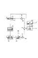
図1に、第1の実施形態に係る音声符号化方法を適用した音声符号化システムが示される。この音声符号化システムは、入力端子101,106と、LPC分析部110と、LPC量子化部111と、LPC合成部120と、聴覚重み付け部130と、適応符号帳141と、パルス位置候補探索部142と、適応代数構造符号帳143と、符号選択部150と、ピッチ周期強調部160と、利得乗算部102,103および加算部104,105から構成される。
【0024】
入力端子101には、符号化すべき入力音声信号が1フレーム分の長さの単位で入力され、これに同期してLPC分析部110で線形予測分析が行われることにより、声道特性に相当する線形予測係数(LPC係数)が求められる。LPC係数はLPC量子化部111で量子化され、この量子化値がLPC合成部120にLPC合成部120の特性を表す合成フィルタ情報として入力されると共に、量子化値を指し示すインデックスAが符号化結果として図示しない多重化部へ出力される。
【0025】
適応符号帳141には、過去にLPC合成部120に入力された駆動信号が格納されている。LPC合成部120の入力となる駆動信号は、線形予測分析における予測残差信号を量子化した信号であり、音の高低の情報などを含む声帯信号に相当する。適応符号帳141は過去の駆動信号からピッチ周期に相当する長さの波形を切り出し、これを繰り返すことでピッチベクトルを生成する。ピッチベクトルは通常、フレームを幾つかに分割したサブフレーム単位で求められる。
【0026】
パルス位置候補探索部142では、適応符号帳141で求められたピッチベクトルを基に、サブフレーム内のどの位置にパルス位置候補を設定するかを計算で求め、その結果を適応代数構造符号帳143に出力する。
【0027】
適応代数構造符号帳143は、パルス位置候補探索部142から入力されたパルス位置候補の中から、ピッチベクトルの影響を差し引いた入力音声信号に対する歪みが聴覚重みの下で最小となるように、所定の本数分のパルス位置とその符号を探索する。
【0028】
適応代数構造符号帳143の出力であるパルス列は、必要に応じてピッチ周期強調部160によってピッチ単位で周期化される。ピッチ周期強調部160では、入力端子106から適応符号帳143の探索で求められたピッチ周期の情報Lが入力され、パルス列にピッチ周期の周期性が与えられる。
【0029】
適応符号帳141から出力されるピッチベクトルおよび適応代数構造符号帳143から出力され、かつ必要に応じてピッチ周期強調部160で周期性が与えられたパルス列は、利得乗算部102,103によりピッチベクトルに対する利得G0および雑音ベクトルに対する利得G1がそれぞれ乗じられた後、加算部104で加え合わせられ、LPC合成部120に駆動信号として入力される。なお、利得G0,G1としては通常、複数の利得を格納した利得符号帳(図示していない)から最適な利得が選ばれる。
【0030】
符号選択部150からは、適応符号帳141に対する探索で選ばれたピッチベクトルを示すインデックスBと、適応代数構造符号帳143に対する探索で選ばれたパルス列を示すインデックスCと、利得符号帳に対する探索で選ばれた利得G0,G1を示すインデックスGが出力される。これらの各インデックスB,C,GとLPC量子化部111からのLPC係数の量子化値である合成フィルタ情報を示すインデックスAが図示しない多重化部で多重化され、ビットストリームとして出力される。
【0031】
次に、本実施形態の特徴部分であるパルス位置候補探索部142と適応代数構造符号帳143について説明する。
【0032】
本実施形態では低符号化レート時にパルスが立つ位置を制限しても、従来のように音質を劣化させずに符号化レートだけを低減させることができるようにするために、パルスは駆動信号のパワの大きい所に集中して立つ性質を利用し、駆動信号のパワの大きい所ほど多くの位置候補が割り振られるようにサブフレーム毎にパルス位置候補が設定される。
【0033】
ピッチベクトルは理想的な駆動信号の形状と似ているため、適応符号帳141の探索により求められたピッチベクトルに基づいてパルス位置候補探索部142でパルス位置候補を設定することは効果的である。ピッチベクトルは、復号化側でも符号化側と同一のものが求められるため、パルス位置候補の適応化に伴って余分な付加情報を発生させる必要はない。
【0034】
パルス位置候補の適応化に際して、パワの大きい所のみに位置候補を割り振ると、パワの小さな区間では連続して位置候補が存在しなくなることが原因で音質が劣化することもある。パルス位置候補の適応化の方法は様々な方法が考えられるが、例えば以下のような方法をとることにより音質劣化の少ない適応化が可能である。
【0035】
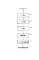
図2に示すフローチャートを用いて、パルス位置候補探索部142によるパルス位置候補の適応化の処理手順を説明する。また、図3に図2の各ステップにおける入力ピッチベクトル波形(F0)、この入力ピッチベクトル波形のパワ(F1)、平滑化したパワ(F2)、この平滑化したパワをサンプル方向に積分した値(F3)を図2に対応させてそれぞれ示す。
【0036】
パワの他に振幅値の絶対値(パワの平方根)など波形の形状を表す他の尺度を用いても同様の処理が可能である。本発明ではこれらをまとめてパワで代表することにする。
【0037】
まず最初に、図3の入力ピッチベクトル(F0)について、パワ(F1)を算出し(ステップS1)、次いでパワ(F1)を平滑化し、平滑化パワ(F2)を得る(ステップS2)。パワの平滑化には、例えば数サンプルの窓で重みを付けて移動平均をとるなどの方法がある。
【0038】
次に、ステップS2で平滑化されたパワをサンプル方向に積分する(ステップS3)。この様子が図3の(F3)に示されている。具体的には、n番目のサンプルの平滑化されたパワをp(n)、この平滑化されたパワp(n)の積分値をq(n)、サブフレーム長をLとすると、積分値q(n)は
q(n)=p(n)+q(n−1)+C (n=0,…,L−1)
で求められる。ただし、Cは定数であり、パルス位置候補の密度の偏りの度合いを調節する。
【0039】
次に、この積分値q(n)を用いてパルス位置候補の算出を行う(ステップS4)。この場合、最終サンプルでの積分値が求める位置候補数がMになるように積分値を正規化する。m番目の候補の位置は、図3の(F3)に示したように積分値と対応させることで、Smとして求めることができる。m=0,…,M−1まで繰り返すことでM個の位置候補を求めることができる。
【0040】
図4に、このようにして求められたパルス位置候補とピッチベクトルのパワとの関係を示す。実線はピッチベクトルのパワ包絡、矢印はパルス位置候補を示している。同図に示されるように、パルス位置候補の分布はピッチベクトルのパワの大きいところでは密となり、パワが小さくなるに従って疎になってゆく。その結果、音質上重要なピッチベクトルのパワの大きいところでは、より正確にパルス位置を選ぶことができる。また、低符号化レート化によってパルス位置候補の数が減少しても、少ないパルス位置候補をピッチベクトルのパワの大きい所に適応的に集中させることで、高音質の符号化が可能となる。
【0041】
次に、このようにして求められた位置候補をチャネル毎に分配する(ステップS5)。分配の方法も様々であるが、図3の(F4)に示したように位置候補は各チャネルが互い違いになるように分配されるのが望ましい。このようにして、適応代数構造符号帳143が求められる。探索では、この適応代数構造符号帳143の各チャネル(Ch1,Ch2,Ch3)から1パルスずつ最適な位置と符号が選ばれ、3本のパルスで構成される雑音ベクトルが生成される。
【0042】
サブフレーム長が80サンプルの場合、パルス候補位置を全チャネル合計で40サンプル程度に削減しても、上記の手法を用いれば聴覚的な劣化はほとんど感じられなくなる。
【0043】
代数構造符号帳ではパルスの振幅は通常+1または−1のどちらかであるが、振幅情報を持つパルスを用いる方法も提案されている、文献4(Chang Deyuan, ”An 8kb/s low complexity ACELP speech codec,” 1996 3rd International Conference on Signal Processing, pp. 671−4, 1996)に示されているようにパルスの振幅を1.0,0.5,0,−0.5,−1.0の中から選択する方法があげられる。また、文献5(K. Ozawa and T. Araseki, ”Low Bit Rate Multi−pulse Speech Coder with Natural Speech Quality,” IEEE Proc. ICASSP’ 86, pp. 457−460, 1986)に示されているパルス音源の一種であるマルチパルス方式なども駆動信号が振幅を持つパルス列から構成される。本発明はこれらの例に代表されるようなパルスが振幅をもつ場合にも適用可能である。
【0044】
次に、図5を用いて図1の音声符号化システムに対応する音声復号化システムについて説明する。
【0045】
図1と同一機能を有する部分に同一符号を付して説明すると、図5の音声復号化システムは、LPC合成部120と、LPC逆量子化部121と、適応符号帳141と、パルス位置候補探索部142と、適応代数構造符号帳143と、ピッチ周期強調部160と、利得乗算部102,103および加算部104から構成され、図1の音声符号化システムから伝送されてきた符号化ストリームが入力される。
【0046】
入力された符号化ストリームは図示しない逆多重化部121に入力され、この逆多重化部121によって前述した合成フィルタ情報のインデックスA、適応符号帳141に対する探索で選ばれたピッチベクトルを示すインデックスB、適応代数構造符号帳143に対する探索で選ばれたパルス列を表すインデックスC、利得符号帳に対する探索で選ばれた利得G0,G1を示すインデックスGおよびピッチ周期を示すインデックスLに分離されて取り出される。
【0047】
インデックスAは、LPC逆量子化部121で復号されて合成フィルタ情報であるLPC係数が求められ、LPC合成部120に入力される。インデックスBおよびCは、適応符号帳141および適応代数構造符号帳143にそれぞれ入力され、これらの符号帳141,143からピッチベクトルおよびパルス列が出力される。この場合、適応代数構造符号帳143は、適応符号帳141から入力されたピッチベクトルに基づいてパルス位置候補探索部142で生成されたた適応代数構造符号帳143とインデックスBから、パルス位置と符号を決定してパルス列を出力する。適応代数構造符号帳143から出力されるパルス列は、必要に応じてピッチ周期強調部160によりピッチ周期Lの周期性が与えられる。
【0048】
適応符号帳141から出力されるピッチベクトルおよび適応代数構造符号帳143から出力され、かつ必要に応じてピッチ周期強調部160で周期性が与えられたパルス列は、利得乗算部102,103によりピッチベクトルに対する利得G0および雑音ベクトルに対する利得G1がそれぞれ乗じられた後、加算部104で加え合わせられてLPC合成部120に駆動信号として入力され、このLPC合成部120から再生音声信号が出力される。利得G0,G1は、インデックスGに従って図示しない利得符号帳から選ばれる。
【0049】
このように本実施形態によれば、音声の品質を維持したまま、ビットレートのみを削減することが可能となり、低符号化レートで高音質の音声符号化/復号化を実現することができる。
【0050】
図6に、本発明の第2の実施形態に係る音声符号化システムが示される。この音声符号化システムは、第1の実施形態による図1に示した構成からパルス位置候補探索部142および適応代数構造符号帳143を取り除き、適応代数構造符号帳143に代わるものとして一般的な雑音符号帳144を備え、さらにパルス整形フィルタ分析部161とパルス整形部162が追加された構成となっている。
【0051】
次に、本実施形態の処理手順について説明すると、入力音声信号のLPC分析およびLPC量子化を行った後、適応符号帳141の探索を行う所までは、第1の実施形態と同じである。雑音符号帳144は、この例では例えば代数構造符号帳により構成される。
【0052】
パルス整形フィルタ分析部161は適応符号帳141の探索で求められたピッチベクトルに基づいてパルス整形部162のフィルタ係数を決定して出力する。パルス整形部162は、雑音符号帳144の出力を整形し雑音ベクトルとして出力する。
【0053】
第1の実施形態と同様に、必要に応じてピッチ周期強調部160を用いて雑音ベクトルが周期化され、ピッチベクトルと雑音ベクトルに対する利得G0,G1が決められインデックスが出力される。パルス整形部162のフィルタ係数はピッチベクトルから求められるため、新たな付加情報を必要としない。
【0054】
本実施形態の特徴は、パルス整形部162をピッチベクトルの波形を基に設定し、代数構造符号帳からなる雑音符号帳144の出力であるパルス列にパルス整形を施す点にある。第1の実施形態で述べたように、低符号化レート化に伴ってパルス位置、パルス数が減少し音質の劣化が目立つようになる。パルス数が減少した場合は「プチプチ」という雑音が復号音声に目立つようになるが、本実施形態のようにパルス整形部162を用いることで、このプチプチ感が大幅に軽減される。
【0055】
パルス整形部162の設計方法としては、様々な方法を用いることができる。第一の例として、合成フィルタを駆動する駆動信号を位相等化すると、それがパルス状の信号になるという性質を利用する方法が考えられる。位相等化の逆フィルタを用いれば、パルス状の信号を入力することで駆動信号状の波形が得られることになる。従来のパルス波形を用いた場合のデメリットは理想的な駆動信号に含まれている位相情報が欠如してしまう点であり、パルス数が少なくなるとこの問題が顕著になる。そこで、この例のように位相情報をパルス整形部162で付加することで、パルス波形からより理想的な駆動信号に近い波形を生成することができる。
【0056】
この第一の例では、位相等化逆フィルタのフィルタ係数の情報を伝送する必要があり、その分だけ符号化レート(bit rate)が増える。そこで、パルス整形部162の第二の例として、位相情報の近似としてピッチベクトルを用いる方法が考えられる。有音区間などではピッチベクトルは、駆動信号と形状が類似しているため、位相情報を取り出すことができる。
【0057】
具体的な方法の一つとして、ピッチベクトルのピーク位置などの同期点を求め、この同期点から数サンプル分の波形を取り出し、これをインパルス応答とするパルス整形フィルタを用いることができる。取り出す波形の長さは2〜3サンプル程度で効果が現われる。また、取り出したサンプルに窓をかけて減衰させてそれを用いるのも効果がある。さらに、ピッチベクトルは復号側でも符号化側と同一のものが得られるため、新たな伝送ビットを必要としない利点もある。雑音符号帳144の探索時には、パルス整形部162は一定であるため、そのインパルス応答をLPC合成部120と合わせて予め計算しておくことで、計算量を削減することができる。
【0058】図7に、図6の音声符号化システムに対応する音声復号化システムが示される。図6と同一機能を有する部分に同一符号を付して説明すると、図7の音声復号化システムは、LPC合成部120と、LPC逆量子化部121と、適応符号帳141と、代数構造符号帳からなる雑音符号帳144と、パルス整形フィルタ分析部161と、パルス整形部162と、ピッチ周期強調部160と、利得乗算部102,103および加算部104から構成され、図6の音声符号化システムから伝送されてきた符号化ストリームが入力される。
【0059】
入力された符号化ストリームは、図示しない逆多重化部に入力され、この逆多重化部によって前述した合成フィルタ情報のインデックスA、適応符号帳141に対する探索で選ばれたピッチベクトルを示すインデックスB、雑音符号帳144に対する探索で選ばれたパルス列を表すインデックスCと、利得符号帳に対する探索で選ばれた利得G0,G1を示すインデックスGに分離されて取り出される。ピッチ周期Lは、インデックスBより算出される。
【0060】
インデックスAは、LPC逆量子化部121で復号されて合成フィルタ情報となり、LPC合成部120に入力される。インデックスBおよびCは適応符号帳141および雑音符号帳144にそれぞれ入力され、これらの符号帳141,144からピッチベクトルおよびパルス列が出力される。
【0061】
この場合、雑音符号帳144から出力されるパルス列は、適応符号帳141の探索で求められたピッチベクトルに基づいてパルス整形フィルタ分析部161により係数が設定されたパルス整形部162により処理された後、必要に応じてピッチ周期強調部160によりピッチ周期Lの周期性が与えられる。
【0062】
適応符号帳141から出力されるピッチベクトルおよび雑音符号帳144から出力され、パルス整形部162およびピッチ周期強調部160を経たパルス列は、利得乗算部102,103によりピッチベクトルに対する利得G0および雑音ベクトルに対する利得G1がそれぞれ乗じられた後、加算部104で加え合わせられ、LPC合成部120に駆動信号として入力され、このLPC合成部120から合成された復号音声信号が出力される。利得G0,G1は、インデックスGに従って図示しない利得符号帳から選ばれる。
【0063】
このように本実施形態によると、パルス整形部162を用いることで、雑音符号帳144に低符号化レート化によってパルス数が減少した代数構造符号帳を用いた場合においても、復号音声の音質を維持したまま符号化レートだけを効果的に削減することが可能になる。
【0064】
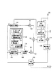
図8に、本発明の第3の実施形態に係る音声符号化システムが示される。この音声符号化システムは、第1の実施形態の構成に第2の実施形態で説明したパルス整形フィルタ分析部161とパルス整形部162を加えた構成になっている。
【0065】
次に、本実施形態の処理手順について説明すると、第1の実施形態と同様にまずLPC分析およびLPC量子化が行われ、適応符号帳141の探索が完了した後、ピッチベクトルがパルス位置候補探索部142とパルス整形フィルタ分析部161に渡される。パルス位置候補探索部142では、第1の実施形態で述べた方法を用いてパルス位置候補が求められ,適応代数構造符号帳143が作られる。パルス整形フィルタ分析部161では、第2の実施形態で述べたようにパルス整形部162の係数が求められる。
【0066】
適応代数構造符号帳143の探索では、出力されたパルス列はパルス整形部162で整形される。実際の探索では、パルス整形部162やピッチ周期強調部160のインパルス応答はLPC合成部120と合わせられ、計算量の削減が行われる。
【0067】
図9に、図8の音声符号化システムに対応する音声復号化システムが示される。この音声復号化システムの動作は第1および第2の実施形態で説明した音声復号化システムの動作から自明であるので、図1、図7および図8と同一部分に同一符号を付して詳細な説明は省略する。
【0068】
このように本実施形態では、第1の実施形態で説明したパルス位置候補探索部142および適応代数構造符号帳143と、第2の実施形態で説明したパルス整形フィルタ分析部161およびパルス整形部162を同時に用いることで、限られた位置候補に少数のパルスを立てる場合でも高い音質を維持することが可能となり、高音質、低符号化レートの音声符号化方式を実現することができる。
【0069】
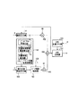
図10に本発明の第4の実施形態に係る音声符号化システムのブロック図を示す。この音声符号化システムでは、第1の実施形態のパルス位置候補探索部がピッチベクトル平滑部171と位置候補密度関数算出部172および位置候補算出部173から構成されている他は、第1の実施形態と同じ構成である。
【0070】
次に、本実施形態の処理手順について説明すると、第1の実施形態と同様に、まずLPC分析およびLPC量子化と、適応符号帳141の探索が完了した後、ピッチベクトルがパルス位置候補探索部142のピッチベクトル平滑部171に渡される。ピッチベクトル平滑部171ではピッチベクトルに対し、例えば図2のフローチャートのステップS1〜S2の処理を行い、ピッチベクトルのパワ包絡を求め、これを出力する。位置候補密度関数算出部172ではパワ包絡を位置候補密度関数に変換し、出力する。位置候補算出部173ではパワ包絡の代わりにこの位置候補密度関数を用いてパルス位置候補を算出し、得られたパルス位置候補に従って適応代数構造符号帳143を作る。以降の処理は第1の実施形態と同様である。
【0071】
本実施形態の特徴は、パルス位置候補探索部142の処理の方法にある。第1の実施形態ではピッチベクトルのパワ包絡をそのまま用いてパルス位置候補の適応化を行っていたのに対し本実施形態ではパワ包絡を位置候補密度関数に変換した後これを用いて適応化を行っている。図11を用いて詳しく説明する。図11(a)がピッチベクトル平滑化部171から出力されたピッチベクトルのパワ包絡である。位置候補密度関数算出部172では、ピッチベクトルのパワ包絡(図11(a))から位置候補密度関数(図11(b))を生成する。この時、図11(c)に示したパワ包絡の値(x)と位置候補密度関数の値(f(x))の対応を示す関数fを用いて変換を行う。関数fの作成方法は例えば多くの学習音声を処理する事で統計的に求めておく方法などがあげられる。
また、関数の代わりにテーブルデータ等を用いることも可能である。
【0072】
パルス位置候補探索部142は変換用の関数fも合めて、符号器と復号器にそれぞれ同一のものを用意するので、適応化に関する情報は送る必要がなく、適応化を行わない場合と比べてビットレートの増加は無い。
【0073】
図12に図10の音声符号化システムに対応する本実施形態の音声復号化システムの構成を示す。この音声復号化システム動作は第1〜3の実施形態で説明した音声復号化システムの動作から自明であるので詳細な説明は省略する。
【0074】
このように本実施形態ではピッチベクトルのパワ包絡の値とパルス位置候補の密度を関数fを用いて変換するため、第1の実施形態に比べて処理手順は僅かに複雑になるが、より正確な位置候補の配分が可能となる。また、第1の実施形態は、本実施形態においてx=f(x)とした場合と考えることができる。
【0075】
図13に本発明の第5の実施形態に係る音声符号化システムのブロック図を示す。この音声符号化システムでは、第1の実施形態のパルス位置候補探索部がピッチフィルタ逆演算部174と平滑化部175および位置候補算出部173から構成されている他は、第1の実施形態と同じ構成である。
【0076】
次に、本実施形態の処理手願について説明すると、第1の実施形態と同様にまず、LPC分析およびLPC量子化と、適応符号帳141の探索が完了した後、ピッチベクトルがパルス位置候補探索部142のピッチフィルタ逆演算部174に渡される。ピッチフィルタ逆演算部174はピッチ周期強調部160の逆特性を表す演算を行う。例えばピッチフィルタの伝達関数P(Z)が
P(z)=1−az^(−L) (1)
で与えられる場合、ピッチフィルタ逆演算部174では伝達関数Q(z)が
Q(Z)=l/(1−baz^(−L)) (2)
で与えられるフィルタを用いる方法が挙げられる。ここでaは定数、bは逆特性の度合を表し、b=1の時Q(z)はP(z)の逆フィルタとなる。入力されたピッチベクトルは逆演算が施された後、出力され、平滑化部175で実施形態4のピッチベクトル平滑化部171と同様の手法でパワ包絡が求められる。位置候補算出部173ではこのパワ包絡に従っでパルス位置候補を選択し、適応代数構造符号帳143を作る。以降の処理は実施形態1と同様である。
【0077】
本実施形態の特徴はピッチ周期強調部160の影響を考慮したピッチベクトルをパルス位置候補の適応化に用いる点である。このようにすることで効率が上がる理由を述べる。
【0078】
適応代数構造符号帳から生成された雑音ベクトルはピッチ周期強調部160でピッチ周期化がされる。周期化に式(1)を用いた場合、サブフレームの先頭に近いパルスはピッチ周期間隔でサブフレーム内で何度も繰り返されるのに対し、後半のパルスほど繰り返される回数が少なくなる。実際に得られた雑音符号ベクトルを観測すると、強いピッチフィルタが用いられる場合ほど先頭に近い位置にパルスが立ちやすい傾向があることが確認できる。このことから、パルス位置はピッチベクトルの形状だけでなく、ピッチフィルタとも関係が深いことがわかる。本実施形態ではピッチフィルタ逆演算部174を用いることにより、ピッチ周期強調部160の影響を考慮したパルス位置候補の適応化を実現している。
【0079】
ところで、第3の実施形態では雑音ベクトルにパルス整形フィルタとピッチフィルタの2種類のフィルタをかけることが可能である。このような場合に本実施形態を適用する場合は、2つのフィルタを合わせた特性を求め、この特性の逆特性をピッチフィルタ逆演算部に用いるのが理想的である。しかし、処理量が増えるため影響の大きなピッチフィルタの特性のみを用いるだけでも効果は得られる。また、ピッチフィルタ逆演算部174と平滑化部175の順序は逆でも実現可能である。
【0080】
図14に図13の音声符号化システムに対応する本実施形態の音声復号化システムの構成を示す。この音声符号化システムの動作は第1乃至4実施形態で説明した音声復号化システムの動作から自明であるので詳細な説明は省略する。
【0081】
図15に本発明の第6の実施形態に係る音声符号化システムのブロック図を示す。この音声符号化システムでは、第1の実施形態の適応代数構造符号帳が雑音ベクトル生成部180と振幅符号帳181に置き替わっている他は、第1の実施形態と同じ構成である。
【0082】
次に、本実施形態の処理手順について説明すると、第1の実施形態と同様にまずLPC分析およびLPC量子化と、適応符号帳141の探索が完了した後、ピッチベクトルがパルス位置探索部174に渡される。パルス位置探索部174では第1の実施形態と同様の手法でピッチベクトルのパワ包絡に基づきパルス位置を求め、雑音ベクトル生成部にこれを出力する。ここで、本実施形態がこれまでの実施形態と異なる点はパルス位置探索部174で得られた位置には雑音ベクトル探索部で全てパルスが立てられる点である。つまり、これまでの実施形態ではパルス位置の候補が求められ、この中から適応代数構造符号帳で最適なパルス位置を選んでいたのに対し、本実施形態ではパルス位置の候補の全部を同時に用いる。従ってパルス位置を選ぶ処理は不要になる。その代わりに、各パルスの振幅を振幅符号帳181から選ぶ処理が追加される。また、出力信号もパルス位置を示す情報cの代わりにパルスの振幅を表す情報Dが出力される。
【0083】
図16を用いて雑音ベクトルの生成方法を詳しく説明する。図16(a)に振幅符号帳から得られた振幅パターンを矢印で示す。この場合、7本のパルスを立てることを想定している。図16(b)と図16(c)の波形はパルス位置探索部174で得られたピッチベクトルパワ包絡とこれに対応するパルス位置(図の○印)である。図16(b)ではパワの山が2箇所あるため7個のパルス位置が2箇所に分散されているのに対し、図16(c)では山が中央に1箇所あるので中央にパルス位置が集中している。図16(d)と図16(e)はそれぞれのパルス位置に図16(a)の振幅のパルスを立てられた雑音ベクトルである。ピッチベクトルパワ包絡に合わせて駆動信号の形状も変化することが分る。既に述べたようにピッチベクトルのパワ包絡の情報は伝送する必要がないため、本実施形態ではビットレートの増加を伴わずに雑音ベクトルの形状を理想的な雑音ベクトルの形に近づけることができる。
【0084】
本実施形態ではビットレートが高くなるに従ってパルスの振幅情報Dも多く送れるようになり品質も向上するが、向上の度合は鈍くなっていく。ある程度高いビットレートでは、振幅情報を増やすよりも選ばれなかった位置にパルスを立てた雑音ベクトルも探索の候補に含めた方が性能が向上する場合がある。具体的には、パルス位置探索部174は異なるパルス位置のパターン(パルスパターン)を出力し、雑音ベクトル生成部ではパルスパターンごとに振幅を探索する。パルスパターンは前述のピッチベクトルに適応化させたパルスパターンの他に、このパルスパターンに選ばれなかったパルス位置から生成されたパルスパターンも用意する。例えばサブフレームの全サンプル位置から適応化で選ばれたサンプル位置を引いた残りを第2のパルスパターンとして2種類のパルスパターンに対して振幅の探索を行う方法が挙げられる。振幅情報に割り当てられるビット数は各パルスパターンごとに異なる構成にすることも可能であり、通常適応化を用いたパルスパターンの方に多くのビットを配分した方が効率が良い。複数のパルスパターンを用いた場合、どのパルスパターンを用いたかを表す情報を情報Dに含めて伝送する必要があり、その分、振幅情報が減ってしまうが、単一のパルスパターンのみを探索するより品質が良い。
【0085】
図17に図15の音声符号化システムに対応する本実施形態の音声復号化システムの構成を示す。この音声復号化システム動作は第1〜5の実施形態で説明した音声復号化システムの動作から自明であるので詳細な説明は省略する。
【0086】
なお、上述の実施形態では音声符号化/復号化方法について説明したが、本発明は音声合成方法にも適用でき、その場合は図5、図7および図9に示した音声復号化システムにおいて、各インデックスを合成したい再生音声信号に基づいて与えればよい。
【0087】
【発明の効果】
以上説明したように、本発明によれば低符号化レート化によってパルス位置やパルス数が削減された代数構造符号帳を用いても、高音質の音声符号化/復号化を行うことができる。
【図面の簡単な説明】
【図1】本発明の第1の実施形態に係る音声符号化システムのブロック図
【図2】第1の実施形態におけるパルス位置候補の選択手順を示すフローチャート
【図3】図2の各ステップでの処理の様子を示す図
【図4】第1の実施形態におけるピッチベクトルのパワ包絡とパルス位置候補の関係を示す図
【図5】第1の実施形態に係る音声復号化システムのブロック図
【図6】本発明の第2の実施形態に係る音声符号化システムのブロック図
【図7】第2の実施形態に係る音声復号化システムのブロック図
【図8】本発明の第3の実施形態に係る音声符号化システムのブロック図
【図9】第3の実施形態に係る音声復号化システムのブロック図
【図10】本発明の第4の実施形態に係る音声符号化化システムのブロック図
【図11】ピッチベクトルパワ包絡、位置候補密度関数、パワー包絡の値と位置候補密度関数の値の関係をそれぞれ示す図
【図12】第4の実施形態に係る復号システムのブロック図
【図13】本発明の第5の実施形態に係る音声符号化化システムのブロック図
【図14】第5の実施形態に係る復号システムのブロック図
【図15】本発明の第6の実施形態に係る音声符号化化システムのブロック図
【図16】雑音ベクトル生成方法を説明するための図
【図17】第6の実施形態に係る復号システムのブロック図
【符号の説明】
101…音声入力端子
102,103…利得乗算部
104,105…加算部
110…LPC分析部
111…LPC量子化部
120…LPC合成部
130…聴覚重み付け部
141…適応符号帳
142…パルス位置候補探索部
143…適応代数構造符号帳
144…雑音符号帳
150…符号選択部
160…ピッチ周期強調部
161…パルス整形フィルタ分析部
162…パルス整形部
171…ピッチベクトル平滑部
172…位置候補密度関数算出部
173…位置候補算出部
174…パルス位置探索部
180…雑音ベクトル生成部
181…振幅符号帳[0001]
TECHNICAL FIELD OF THE INVENTION
The present invention relates to a low coding rate speech encoding / decoding method used for digital telephones, voice memos, and the like.
[0002]
[Prior art]
2. Description of the Related Art In recent years, as a coding technique for compressing voice and musical sound into a small amount of information for transmission and storage on a mobile phone or the Internet, a CELP method (Code Excited Linear Prediction (MR Schroeder and BS Atal, "Code Excited Linear Prediction (CELP): High Quality Speech at Very Low Bit Rates," Proc. ICASSP, pp. 937-940, 1985 (Literature 1) and W. S. Kj. Improved Speech Quality and Efficient Vector Quantification in SELP, "Proc. ICASS P, pp. 155-158, 1988 (Reference 2)).
[0003]
CELP is a coding method based on linear prediction analysis, and an input speech signal is divided into a linear prediction coefficient representing phoneme information and a prediction residual signal representing a pitch or the like by linear prediction analysis. A recursive digital filter called a synthesis filter is configured based on the linear prediction coefficients, and the original input audio signal can be restored by inputting a prediction residual signal as a drive signal to the synthesis filter.
[0004]
In order to perform encoding at a low rate, it is necessary to encode a linear prediction coefficient, which is synthesis filter information representing characteristics of a synthesis filter, and a prediction residual signal, which is a drive signal for driving the synthesis filter, with a smaller amount of information. is there. In the CELP method, a signal obtained by encoding a prediction residual signal is generated as a drive signal by multiplying two types of signals, that is, a pitch vector and a noise vector, by an appropriate gain and then adding the signals. A method of generating a pitch vector is described in, for example,
[0005]
In addition to the method of
The noise vector is usually generated by storing a large number of candidates in a random codebook and selecting an optimum one from the stored candidates. As a noise vector search method, all the noise vectors are added to the pitch vector, then a synthetic speech signal is generated through a synthesis filter, and the distortion of the synthesized speech signal with respect to the input speech signal is evaluated. A method of selecting a noise vector for generating an audio signal is used. Therefore, how to efficiently store the noise vector in the noise codebook is an important point of the CELP method.
[0006]
The Algebraic Codebook (JP P. Adoul et al, "Fast CELP Coding based on algebraic codes", Proc. ICASPSP '87, pp. 1957-1960 (pp. 1957-1960) describes the noise vector as a pulse. It is a simple structure expressed only by presence / absence and polarity (+,-). The algebraic structure codebook has features that it is not necessary to store a code vector and the amount of calculation is small as compared with a method using a noise codebook storing a plurality of noise vectors. In recent years, it has been used in various standard systems because it has the same sound quality as the conventional system.
[0007]
[Problems to be solved by the invention]
However, in the algebraic structure codebook, as the coding bit rate (coding rate) decreases, the deterioration of sound quality becomes noticeable. One of the reasons is lack of pulse position information. In other words, although the position information of the pulse is algebraically simplified in the algebraic structure codebook, the above advantage is obtained. However, at a low coding rate, a position candidate exists at a position where a pulse does not need to be raised, , The sound quality is degraded as well as the efficiency is low.
[0008]
Another reason that sound quality is degraded when an algebraic structure codebook is used is a shortage of pulses. When the number of pulses is insufficient, the noise "bubble wrap" becomes noticeable in the decoded speech. This is because the drive signal is generated from the pulse train, and as the number of pulses decreases, the presence / absence of the pulse becomes more audible. In order to improve the sound quality, it is necessary to reduce the bubble wrap.
[0009]
As described above, the conventional algebraic structure codebook has a simple structure and an advantage that the amount of calculation is small.On the other hand, when the coding rate becomes low, the position information and the number of pulses of the pulse train constituting the driving signal of the synthesis filter become low. There is a problem that the sound quality of the decoded voice is deteriorated due to the shortage.
[0010]
SUMMARY OF THE INVENTION It is an object of the present invention to provide a speech encoding / decoding method capable of obtaining good sound quality even at a low encoding rate.
[0011]
[Means for Solving the Problems]
The present invention provides a step of generating information representing at least characteristics of a synthesis filter of an audio signal, and a signal for driving the synthesis filter, from a pulse position candidate that adaptively changes according to the characteristic of the audio signal. Generating a drive signal including a pulse train generated by arranging pulses at a selected predetermined number of pulse positions.
[0012]
According to the present invention, a driving signal including a pulse train generated by arranging pulses at a predetermined number of pulse positions selected from pulse position candidates that adaptively change according to the properties of an audio signal is input to a synthesis filter. To provide an audio decoding method for decoding an audio signal.
[0013]
In the speech encoding / decoding method according to the present invention, the drive signal for driving the synthesis filter arranges pulses at a predetermined number of pulse positions selected from pulse position candidates that change adaptively according to the properties of the speech signal. And the pulse train generated by the operation. More specifically, the pulse position candidates are arranged such that the greater the power of the audio signal, the more candidates there are.
[0014]
In addition, the drive signal is configured to include a pulse train generated by arranging pulses at all pulse position candidates that adaptively change according to the properties of the audio signal and optimizing the amplitude of each pulse by a predetermined means. You can also. In this case, more specifically, the pulse position candidates are arranged such that there are more candidates as the power of the audio signal increases.
[0015]
Further, the drive signal is a pulse train generated by arranging pulses at a predetermined number of pulse positions selected from first pulse position candidates that adaptively change according to the properties of the audio signal, or Using any one of the pulse trains generated by arranging pulses at a predetermined number of pulse positions selected from the second pulse position candidates consisting of part or all of the positions not used as the pulse position candidates It can also be generated. In this case, more specifically, the first pulse position candidates are arranged such that there are more candidates as the power of the audio signal is higher.
[0016]
When the drive signal includes a pitch vector and a noise vector, the noise vector is generated by arranging pulses at a predetermined number of pulse positions selected from pulse position candidates that change according to the shape of the pitch vector. You. In this case, more specifically, the pulse position candidates are arranged such that the greater the power of the pitch vector, the more candidates there are.
[0017]
Further, the noise vector is configured using a pulse train generated by arranging pulses at a predetermined number of pulse positions selected from position candidates set based on the position candidate density function determined from the shape of the pitch vector. You can also. In this case, more specifically, the pulse position candidates are arranged such that there are more candidates as the position candidate density function value increases, and the position candidate density function is the probability of the pitch vector power and the pulse being arranged. Is a function obtained in advance.
[0018]
Further, when a correction means such as a pitch cycle emphasis filter is used for the noise vector, a predetermined pitch selected from pulse position candidates that change in accordance with the shape of the inversely corrected pitch vector obtained by performing processing based on the inverse characteristic on the pitch vector. Is generated by arranging the pulses at the pulse positions of the number. In this case, more specifically, the pulse position candidates are arranged so that there are more candidates as the power of the inverse correction pitch vector is larger.
[0019]
By adaptively changing the pulse position candidates according to the properties such as the power distribution of the audio signal in this way, even when using an algebraic structure codebook in which the pulse positions and the number of pulses are reduced due to a lower coding rate. The coding efficiency is improved, and the coding rate can be reduced while maintaining the sound quality of the decoded speech. In addition, by using a pitch vector to generate a pulse position candidate, it is possible to adapt the pulse position candidate without requiring additional information.
[0020]
In another speech encoding / decoding method according to the present invention, when the drive signal includes a pitch vector and a noise vector, the method includes a pulse train shaped by pulse shaping means having characteristics determined based on the shape of the pitch vector. A drive signal is generated.
[0021]
With such a configuration, the pulse-like noise included in the decoded speech due to the decrease in the number of pulses is reduced, and the sound quality of the decoded speech is maintained even when the pulse position and the number of pulses are reduced by lowering the coding rate. It is possible to reduce the coding rate.
[0022]
Furthermore, in the speech encoding / decoding method according to the present invention, the speech signal is generated by arranging pulses at a predetermined number of pulse positions selected from pulse position candidates that adaptively change according to the properties of the speech signal. A drive signal including the generated pulse train may be generated, and the pulse train may be shaped by a pulse shaping unit having characteristics determined based on the shape of the pitch vector.
[0023]
BEST MODE FOR CARRYING OUT THE INVENTION
FIG. 1 shows a speech encoding system to which the speech encoding method according to the first embodiment is applied. This speech coding system includes
[0024]
An input audio signal to be encoded is input to the
[0025]
The
[0026]
The pulse position
[0027]
The adaptive
[0028]
The pulse train output from the adaptive
[0029]
The pitch train output from the
[0030]
The
[0031]
Next, the pulse position
[0032]
In the present embodiment, even if the position where the pulse rises at the time of the low encoding rate is limited, the pulse is used to reduce only the encoding rate without deteriorating the sound quality as in the related art. The pulse position candidates are set for each sub-frame so that the position where the power of the drive signal is higher is allocated more position candidates by utilizing the property of standing concentrated on the position where the power is higher.
[0033]
Since the pitch vector is similar to the shape of an ideal drive signal, it is effective to set the pulse position candidate in the pulse position
[0034]
If the position candidates are assigned only to places where the power is large when adapting the pulse position candidates, the sound quality may be degraded due to the absence of the position candidates continuously in the section where the power is small. Various methods of adapting the pulse position candidates are conceivable. For example, by adopting the following method, adaptation with less sound quality deterioration is possible.
[0035]
With reference to the flowchart shown in FIG. 2, a description will be given of a processing procedure of pulse position candidate adaptation by the pulse position
[0036]
Similar processing can be performed by using other scales representing the waveform shape such as the absolute value of the amplitude value (the square root of the power) in addition to the power. In the present invention, these are collectively represented by power.
[0037]
First, the power (F1) is calculated for the input pitch vector (F0) of FIG. 3 (step S1), and then the power (F1) is smoothed to obtain a smoothed power (F2) (step S2). For power smoothing, for example, there is a method of taking a moving average by weighting in a window of several samples.
[0038]
Next, the power smoothed in step S2 is integrated in the sample direction (step S3). This situation is shown in (F3) of FIG. Specifically, assuming that the smoothed power of the n-th sample is p (n), the integrated value of the smoothed power p (n) is q (n), and the subframe length is L, the integrated value is q (n) is
q (n) = p (n) + q (n-1) + C (n = 0,..., L-1)
Is required. Here, C is a constant, and adjusts the degree of bias in the density of the pulse position candidates.
[0039]
Next, a pulse position candidate is calculated using the integrated value q (n) (step S4). In this case, the integral value is normalized such that the number of position candidates for which the integral value in the final sample is obtained is M. The position of the m-th candidate can be obtained as Sm by associating it with the integral value as shown in (F3) of FIG. By repeating the processing until m = 0,..., M−1, M position candidates can be obtained.
[0040]
FIG. 4 shows the relationship between the pulse position candidates thus obtained and the power of the pitch vector. The solid line indicates the power envelope of the pitch vector, and the arrows indicate pulse position candidates. As shown in the figure, the distribution of the pulse position candidates becomes dense where the power of the pitch vector is large, and becomes sparse as the power becomes small. As a result, where the power of the pitch vector that is important for sound quality is large, the pulse position can be selected more accurately. Further, even if the number of pulse position candidates decreases due to the lowering of the coding rate, high-quality encoding becomes possible by adaptively concentrating a small number of pulse position candidates in a place where the power of the pitch vector is large.
[0041]
Next, the position candidates thus obtained are distributed for each channel (step S5). Although there are various distribution methods, as shown in (F4) of FIG. 3, it is desirable that the position candidates are distributed so that each channel is alternated. In this way, the adaptive
[0042]
When the sub-frame length is 80 samples, even if the pulse candidate positions are reduced to about 40 samples in all channels in total, the above method hardly causes auditory deterioration.
[0043]
In the algebraic structure codebook, the pulse amplitude is usually either +1 or -1, but a method using a pulse having amplitude information has also been proposed. Reference 4 (Chang Deyuan, "An 8 kb / s low complexity ACELP speech") codec, "1996 3rd International Conference on Signal Processing, pp. 671-4, 1996), with pulse amplitudes of 1.0, 0.5, 0, -0.5, -1.0. There is a method of selecting from among them. Also, reference 5 (K. Ozawa and T. Araseki, "Low Bit Rate Multi-pulse Speech Coder with Natural Speech Quality," IEEE Proc. ICASP. 86, p. The multi-pulse method, which is one of the above, is also composed of a pulse train having a drive signal having an amplitude. The present invention is also applicable to a case where a pulse as represented by these examples has an amplitude.
[0044]
Next, a speech decoding system corresponding to the speech encoding system of FIG. 1 will be described with reference to FIG.
[0045]
The parts having the same functions as those in FIG. 1 are denoted by the same reference numerals. The speech decoding system in FIG. 5 includes an
[0046]
The input coded stream is input to a demultiplexing unit 121 (not shown), and the index A of the synthesis filter information and the index B indicating the pitch vector selected in the search for the
[0047]
The index A is decoded by the LPC
[0048]
The pitch train output from the
[0049]
As described above, according to the present embodiment, it is possible to reduce only the bit rate while maintaining the audio quality, and it is possible to realize audio encoding / decoding with high audio quality at a low encoding rate.
[0050]
FIG. 6 shows a speech encoding system according to the second embodiment of the present invention. This speech coding system removes the pulse position
[0051]
Next, the processing procedure of the present embodiment is the same as that of the first embodiment up to the point of performing LPC analysis and LPC quantization of an input speech signal and then searching the
[0052]
The pulse shaping
[0053]
Similarly to the first embodiment, the noise vector is periodicized using the pitch
[0054]
The feature of this embodiment lies in that the
[0055]
Various methods can be used as a design method of the
[0056]
In the first example, it is necessary to transmit the information of the filter coefficient of the phase equalization inverse filter, and the coding rate (bit rate) increases accordingly. Thus, as a second example of the
[0057]
As a specific method, a pulse shaping filter that determines a synchronization point such as a peak position of a pitch vector, extracts a waveform of several samples from the synchronization point, and uses the waveform as an impulse response can be used. The effect appears when the length of the extracted waveform is about two to three samples. It is also effective to apply a window to the sample taken out and attenuate it. Furthermore, since the same pitch vector can be obtained on the decoding side as on the encoding side, there is also an advantage that a new transmission bit is not required. At the time of searching
FIG. 7 shows a speech decoding system corresponding to the speech encoding system of FIG. The parts having the same functions as those in FIG. 6 will be described with the same reference numerals. The speech decoding system in FIG. 7 includes an
[0059]
The input coded stream is input to a demultiplexing unit (not shown), and the index A of the synthesis filter information described above by the demultiplexing unit, the index B indicating the pitch vector selected in the search for the
[0060]
The index A is decoded by the LPC
[0061]
In this case, the pulse train output from the
[0062]
The pulse train output from the
[0063]
As described above, according to the present embodiment, by using the
[0064]
FIG. 8 shows a speech coding system according to the third embodiment of the present invention. This speech coding system has a configuration obtained by adding the pulse shaping
[0065]
Next, the processing procedure of the present embodiment will be described. As in the first embodiment, first, LPC analysis and LPC quantization are performed, and after the search of the
[0066]
In the search of the adaptive
[0067]
FIG. 9 shows a speech decoding system corresponding to the speech encoding system of FIG. Since the operation of this speech decoding system is obvious from the operation of the speech decoding system described in the first and second embodiments, the same reference numerals are given to the same parts as in FIGS. Detailed description is omitted.
[0068]
Thus, in the present embodiment, the pulse position
[0069]
FIG. 10 shows a block diagram of a speech coding system according to the fourth embodiment of the present invention. In this speech coding system, the pulse position candidate search unit of the first embodiment is configured by a pitch
[0070]
Next, the processing procedure of the present embodiment will be described. Similar to the first embodiment, after the LPC analysis and LPC quantization and the search of the
[0071]
The feature of the present embodiment lies in the processing method of the pulse position
Further, table data or the like can be used instead of the function.
[0072]
Since the pulse position
[0073]
FIG. 12 shows the configuration of the speech decoding system of the present embodiment corresponding to the speech encoding system of FIG. Since the operation of the speech decoding system is obvious from the operation of the speech decoding system described in the first to third embodiments, a detailed description will be omitted.
[0074]
As described above, in the present embodiment, since the value of the power envelope of the pitch vector and the density of the pulse position candidate are converted using the function f, the processing procedure is slightly complicated as compared with the first embodiment, but is more accurate. Distribution of the position candidates can be realized. Further, the first embodiment can be considered as a case where x = f (x) in the present embodiment.
[0075]
FIG. 13 shows a block diagram of a speech coding system according to the fifth embodiment of the present invention. In this speech coding system, the pulse position candidate search unit of the first embodiment is configured by a pitch filter
[0076]
Next, the processing application of the present embodiment will be described. As in the first embodiment, after the LPC analysis and LPC quantization and the search of the
P (z) = 1−az ^ (− L) (1)
When the transfer function Q (z) is obtained by the pitch filter
Q (Z) = 1 / (1-baz ^ (− L)) (2)
And a method using a filter given by Here, a is a constant, b represents the degree of the inverse characteristic, and when b = 1, Q (z) is an inverse filter of P (z). The input pitch vector is output after being subjected to an inverse operation, and the power envelope is obtained by the smoothing
[0077]
A feature of the present embodiment is that a pitch vector in consideration of the influence of the pitch
[0078]
The noise vector generated from the adaptive algebraic structure codebook is pitch-periodized by the pitch
[0079]
By the way, in the third embodiment, it is possible to apply two types of filters, a pulse shaping filter and a pitch filter, to the noise vector. When the present embodiment is applied to such a case, it is ideal that a characteristic obtained by combining two filters is obtained, and an inverse characteristic of the characteristic is used for the pitch filter inverse operation unit. However, the effect can be obtained only by using only the characteristics of the pitch filter which has a large influence because the processing amount increases. Further, the order of the pitch filter
[0080]
FIG. 14 shows the configuration of the speech decoding system of the present embodiment corresponding to the speech encoding system of FIG. Since the operation of the speech encoding system is obvious from the operation of the speech decoding system described in the first to fourth embodiments, detailed description will be omitted.
[0081]
FIG. 15 shows a block diagram of a speech coding system according to the sixth embodiment of the present invention. This speech coding system has the same configuration as that of the first embodiment, except that the adaptive algebraic structure codebook of the first embodiment is replaced by a
[0082]
Next, the processing procedure of this embodiment will be described. First, after the LPC analysis and LPC quantization and the search of the
[0083]
A method of generating a noise vector will be described in detail with reference to FIG. FIG. 16A shows an amplitude pattern obtained from the amplitude codebook by an arrow. In this case, it is assumed that seven pulses are made. The waveforms in FIGS. 16B and 16C are the pitch vector power envelope obtained by the pulse
[0084]
In the present embodiment, as the bit rate increases, more pulse amplitude information D can be sent, and the quality is improved, but the degree of improvement is reduced. At a somewhat high bit rate, performance may be improved by including noise vectors with pulses at unselected positions as search candidates rather than increasing amplitude information. Specifically, the pulse
[0085]
FIG. 17 shows the configuration of the speech decoding system of the present embodiment corresponding to the speech encoding system of FIG. Since the operation of the speech decoding system is obvious from the operation of the speech decoding system described in the first to fifth embodiments, detailed description will be omitted.
[0086]
In the above embodiment, the speech encoding / decoding method has been described. However, the present invention can also be applied to a speech synthesis method. In that case, in the speech decoding system shown in FIGS. 5, 7, and 9, What is necessary is just to give each index based on the reproduced audio signal to be synthesized.
[0087]
【The invention's effect】
As described above, according to the present invention, high-quality speech encoding / decoding can be performed even when using an algebraic structure codebook in which the pulse position and the number of pulses are reduced by reducing the encoding rate.
[Brief description of the drawings]
FIG. 1 is a block diagram of a speech encoding system according to a first embodiment of the present invention.
FIG. 2 is a flowchart illustrating a pulse position candidate selection procedure according to the first embodiment;
FIG. 3 is a diagram showing a state of processing in each step of FIG. 2;
FIG. 4 is a diagram illustrating a relationship between a power envelope of a pitch vector and a pulse position candidate according to the first embodiment.
FIG. 5 is a block diagram of a speech decoding system according to the first embodiment;
FIG. 6 is a block diagram of a speech encoding system according to a second embodiment of the present invention.
FIG. 7 is a block diagram of a speech decoding system according to a second embodiment;
FIG. 8 is a block diagram of a speech encoding system according to a third embodiment of the present invention.
FIG. 9 is a block diagram of a speech decoding system according to a third embodiment.
FIG. 10 is a block diagram of a speech coding system according to a fourth embodiment of the present invention.
FIG. 11 is a diagram showing the relationship between the values of the pitch vector power envelope, the position candidate density function, the power envelope, and the position candidate density function.
FIG. 12 is a block diagram of a decoding system according to a fourth embodiment;
FIG. 13 is a block diagram of a speech encoding system according to a fifth embodiment of the present invention.
FIG. 14 is a block diagram of a decoding system according to a fifth embodiment;
FIG. 15 is a block diagram of a speech encoding system according to a sixth embodiment of the present invention.
FIG. 16 is a diagram for explaining a noise vector generation method.
FIG. 17 is a block diagram of a decoding system according to a sixth embodiment;
[Explanation of symbols]
101 ... Audio input terminal
102, 103 ... gain multiplication unit
104, 105 ... addition section
110 ... LPC analysis unit
111 LPC quantizer
120 ... LPC synthesis unit
130 ... auditory weighting unit
141 ... Adaptive codebook
142... Pulse position candidate search unit
143 ... Adaptive algebraic structure codebook
144: Noise codebook
150 ... code selection unit
160 pitch pitch emphasis unit
161: pulse shaping filter analyzer
162 ... Pulse shaping unit
171: pitch vector smoothing unit
172 position candidate density function calculator
173: position candidate calculation unit
174: pulse position search unit
180 ... Noise vector generation unit
181 ... amplitude codebook
Claims (8)
Priority Applications (1)
| Application Number | Priority Date | Filing Date | Title |
|---|---|---|---|
| JP36783698A JP3579276B2 (en) | 1997-12-24 | 1998-12-24 | Audio encoding / decoding method |
Applications Claiming Priority (3)
| Application Number | Priority Date | Filing Date | Title |
|---|---|---|---|
| JP35574897 | 1997-12-24 | ||
| JP9-355748 | 1997-12-24 | ||
| JP36783698A JP3579276B2 (en) | 1997-12-24 | 1998-12-24 | Audio encoding / decoding method |
Publications (2)
| Publication Number | Publication Date |
|---|---|
| JPH11259098A JPH11259098A (en) | 1999-09-24 |
| JP3579276B2 true JP3579276B2 (en) | 2004-10-20 |
Family
ID=26580323
Family Applications (1)
| Application Number | Title | Priority Date | Filing Date |
|---|---|---|---|
| JP36783698A Expired - Fee Related JP3579276B2 (en) | 1997-12-24 | 1998-12-24 | Audio encoding / decoding method |
Country Status (1)
| Country | Link |
|---|---|
| JP (1) | JP3579276B2 (en) |
Families Citing this family (5)
| Publication number | Priority date | Publication date | Assignee | Title |
|---|---|---|---|---|
| KR100465316B1 (en) * | 2002-11-18 | 2005-01-13 | 한국전자통신연구원 | Speech encoder and speech encoding method thereof |
| US7991611B2 (en) | 2005-10-14 | 2011-08-02 | Panasonic Corporation | Speech encoding apparatus and speech encoding method that encode speech signals in a scalable manner, and speech decoding apparatus and speech decoding method that decode scalable encoded signals |
| CN101765880B (en) * | 2007-07-27 | 2012-09-26 | 松下电器产业株式会社 | Audio encoding device and audio encoding method |
| US8768690B2 (en) | 2008-06-20 | 2014-07-01 | Qualcomm Incorporated | Coding scheme selection for low-bit-rate applications |
| US20090319261A1 (en) * | 2008-06-20 | 2009-12-24 | Qualcomm Incorporated | Coding of transitional speech frames for low-bit-rate applications |
-
1998
- 1998-12-24 JP JP36783698A patent/JP3579276B2/en not_active Expired - Fee Related
Also Published As
| Publication number | Publication date |
|---|---|
| JPH11259098A (en) | 1999-09-24 |
Similar Documents
| Publication | Publication Date | Title |
|---|---|---|
| EP0926660B1 (en) | Speech encoding/decoding method | |
| JP3346765B2 (en) | Audio decoding method and audio decoding device | |
| RU2316059C2 (en) | Method and device for quantizing amplification in broadband speech encoding with alternating bitrate | |
| WO1998006091A1 (en) | Voice encoder, voice decoder, recording medium on which program for realizing voice encoding/decoding is recorded and mobile communication apparatus | |
| KR20020077389A (en) | Indexing pulse positions and signs in algebraic codebooks for coding of wideband signals | |
| JPH08263099A (en) | Encoder | |
| JP3343082B2 (en) | CELP speech encoder | |
| JPH08272395A (en) | Voice encoding device | |
| JP4008607B2 (en) | Speech encoding / decoding method | |
| JP3746067B2 (en) | Speech decoding method and speech decoding apparatus | |
| JP3582589B2 (en) | Speech coding apparatus and speech decoding apparatus | |
| JP3579276B2 (en) | Audio encoding / decoding method | |
| JP3199142B2 (en) | Method and apparatus for encoding excitation signal of speech | |
| JP3268750B2 (en) | Speech synthesis method and system | |
| JP3303580B2 (en) | Audio coding device | |
| JP4578145B2 (en) | Speech coding apparatus, speech decoding apparatus, and methods thereof | |
| JP3916934B2 (en) | Acoustic parameter encoding, decoding method, apparatus and program, acoustic signal encoding, decoding method, apparatus and program, acoustic signal transmitting apparatus, acoustic signal receiving apparatus | |
| JP3232701B2 (en) | Audio coding method | |
| JP3490325B2 (en) | Audio signal encoding method and decoding method, and encoder and decoder thereof | |
| JP2968109B2 (en) | Code-excited linear prediction encoder and decoder | |
| JP3954716B2 (en) | Excitation signal encoding apparatus, excitation signal decoding apparatus and method thereof, and recording medium | |
| JP2002073097A (en) | Celp type voice coding device and celp type voice decoding device as well as voice encoding method and voice decoding method | |
| JP3552201B2 (en) | Voice encoding method and apparatus | |
| JP3292227B2 (en) | Code-excited linear predictive speech coding method and decoding method thereof | |
| JP3232728B2 (en) | Audio coding method |
Legal Events
| Date | Code | Title | Description |
|---|---|---|---|
| A977 | Report on retrieval |
Free format text: JAPANESE INTERMEDIATE CODE: A971007 Effective date: 20040123 |
|
| A131 | Notification of reasons for refusal |
Free format text: JAPANESE INTERMEDIATE CODE: A131 Effective date: 20040203 |
|
| A521 | Request for written amendment filed |
Free format text: JAPANESE INTERMEDIATE CODE: A523 Effective date: 20040405 |
|
| TRDD | Decision of grant or rejection written | ||
| A01 | Written decision to grant a patent or to grant a registration (utility model) |
Free format text: JAPANESE INTERMEDIATE CODE: A01 Effective date: 20040713 |
|
| A61 | First payment of annual fees (during grant procedure) |
Free format text: JAPANESE INTERMEDIATE CODE: A61 Effective date: 20040715 |
|
| FPAY | Renewal fee payment (event date is renewal date of database) |
Free format text: PAYMENT UNTIL: 20080723 Year of fee payment: 4 |
|
| FPAY | Renewal fee payment (event date is renewal date of database) |
Free format text: PAYMENT UNTIL: 20090723 Year of fee payment: 5 |
|
| FPAY | Renewal fee payment (event date is renewal date of database) |
Free format text: PAYMENT UNTIL: 20090723 Year of fee payment: 5 |
|
| FPAY | Renewal fee payment (event date is renewal date of database) |
Free format text: PAYMENT UNTIL: 20100723 Year of fee payment: 6 |
|
| FPAY | Renewal fee payment (event date is renewal date of database) |
Free format text: PAYMENT UNTIL: 20110723 Year of fee payment: 7 |
|
| FPAY | Renewal fee payment (event date is renewal date of database) |
Free format text: PAYMENT UNTIL: 20120723 Year of fee payment: 8 |
|
| FPAY | Renewal fee payment (event date is renewal date of database) |
Free format text: PAYMENT UNTIL: 20130723 Year of fee payment: 9 |
|
| LAPS | Cancellation because of no payment of annual fees |