JP3577458B2 - Wet electrophotographic equipment - Google Patents
Wet electrophotographic equipment Download PDFInfo
- Publication number
- JP3577458B2 JP3577458B2 JP2000333923A JP2000333923A JP3577458B2 JP 3577458 B2 JP3577458 B2 JP 3577458B2 JP 2000333923 A JP2000333923 A JP 2000333923A JP 2000333923 A JP2000333923 A JP 2000333923A JP 3577458 B2 JP3577458 B2 JP 3577458B2
- Authority
- JP
- Japan
- Prior art keywords
- carrier liquid
- cyclodextrin
- aqueous solution
- latent image
- volatile component
- Prior art date
- Legal status (The legal status is an assumption and is not a legal conclusion. Google has not performed a legal analysis and makes no representation as to the accuracy of the status listed.)
- Expired - Lifetime
Links
Images
Classifications
-
- G—PHYSICS
- G03—PHOTOGRAPHY; CINEMATOGRAPHY; ANALOGOUS TECHNIQUES USING WAVES OTHER THAN OPTICAL WAVES; ELECTROGRAPHY; HOLOGRAPHY
- G03G—ELECTROGRAPHY; ELECTROPHOTOGRAPHY; MAGNETOGRAPHY
- G03G15/00—Apparatus for electrographic processes using a charge pattern
- G03G15/06—Apparatus for electrographic processes using a charge pattern for developing
- G03G15/10—Apparatus for electrographic processes using a charge pattern for developing using a liquid developer
- G03G15/107—Condensing developer fumes
Landscapes
- Physics & Mathematics (AREA)
- General Physics & Mathematics (AREA)
- Wet Developing In Electrophotography (AREA)
Description
【0001】
【発明の属する技術分野】
本発明は、湿式電子写真装置に係わり、特に揮発したキャリア液を回収・除去するキャリア液除去装置を具備する湿式電子写真装置に関する。
【0002】
【従来の技術】
液体現像剤を用いた電子写真装置は、乾式電子写真装置では実現できない利点を有しており、近年その価値が見直されつつある。例えば、液体現像剤はキャリア液中にトナー粒子を分散させたものであるために、サブミクロンサイズの極めて微細なトナー粒子を用いることができるため高画質を実現できること、少量のトナー粒子で十分な画像濃度が得られるため経済的であるうえに印刷(例えばオフセット印刷)並みの質感を実現できること、比較的低温でトナー粒子を用紙に定着出来るため省エネルギーを実現できること、などが乾式に対する湿式電子写真の主な利点である。
【0003】
一方、従来の液体現像剤による湿式電子写真技術にはいくつかの本質的な問題点が含まれており、そのために長い間乾式技術の独壇場を許してきた。
【0004】
例えば、前述したキャリア液として、高抵抗ないしは絶縁性の液体を使用しなければならず、キャリア液として石油系溶剤を用いなければならなかった。この石油系溶剤は揮発性が高く、また臭気を放つために、オフィスなどの居室での用途が実現されなかった。
【0005】
揮発性の高いキャリア液の処理としては、従来から種々行われており、例えば、特開昭48−82835号公報では筐体内部のキャリア液蒸気を吸引して液化回収を行い、キャリア液蒸気が筐体外部へ放出するのを抑制している。しかし、冷却によってキャリア液蒸気を液化して回収する手法を採用しており、この場合、キャリア液を冷却するためにはキャリア液蒸気と混合している水蒸気なども同時に冷却しなければならないため、キャリア液蒸気の回収効率が悪い。また、液化する方法以外にも、キャリア液蒸気を活性炭などの捕集剤に吸着させることで回収する方法もあるが、活性炭は初期の極短期間回収特性は良好であるが、その期間を経過した後は、回収特性が急激に低下し、安定してキャリア液蒸気を回収することが困難であったり、また、活性炭を捕集剤として使用した場合キャリア液の回収量が視覚的に分からないために、捕集剤の交換の目安がつきにくいという問題があった。
【0006】
【発明が解決しようとする課題】
上述したように、従来の湿式電子写真装置では、例えば活性炭などの除去剤を用いてキャリア液揮発成分の回収除去を行っていたが、活性炭はキャリア液揮発成分の回収能の低下が視覚的に分からないという問題があった。
【0007】
本発明はこのような問題に鑑みて為されたものであり、除去剤の交換の目安を容易に判断できるキャリア液除去装置を備えた湿式電子写真装置を提供することを目的とする。
【0008】
【課題を解決するための手段】
本発明の湿式電子写真装置は、静電潜像保持体と、前記潜像保持体上に静電潜像を形成し前記静電潜像をキャリア液およびこのキャリア液中に分散したトナー粒子を備えた液体現像剤で現像する画像形成装置と、前記静電潜像保持体及び画像形成装置を収容する筐体と、この筐体内で揮発して発生したキャリア液揮発成分を除去するキャリア液除去装置とを有する湿式電子写真装置において、前記キャリア液除去装置は、前記キャリア液揮発成分を含有する気体中にサイクロデキストリン水溶液を除去剤として散布する霧化器を具備することを特徴とする。
【0009】
前記キャリア液除去装置は、前記キャリア液揮発成分を含有する気体を導入する導入口および、前記キャリア液揮発成分を除去した残存ガスを排出する排出口を有する除去容器と、前記吸引口および前記排出口に配置された気相分離フィルターと、前記除去容器内にサイクロデキストリン水溶液を散布する前記霧化器とを有する。
【0010】
前記除去容器の底部に前記サイクロデキストリン水溶液を貯蔵し、超音波振動子からなる前記霧化器を前記サイクロデキストリン水溶液中に配置することができる。
【0011】
本発明の湿式電子写真装置は、静電潜像保持体上に静電潜像を形成し、前記静電潜像をキャリア液およびこのキャリア液中に分散したトナー粒子を備えた液体現像剤で現像する画像形成装置と、前記静電潜像保持体及び前記画像形成装置を収容する筐体と、前記キャリア液が揮発して発生したキャリア液揮発成分を前記筐体内から除去するキャリア液除去装置とを有する湿式電子写真装置において、前記キャリア液除去装置は、前記混合気体を導入する導入口および、前記キャリア液揮発成分を除去した残存ガスを排出する排出口を有する除去容器と、この除去容器内に、前記キャリア液と接触して固体状の包接化合物を生成するサイクロデキストリンを含有する水溶液を散布する霧化器と、前記液除去容器中で回収した未反応の前記サイクロデキストリン水溶液を固体成分から分離する分離手段と、前記分離手段によって分離された水溶液を前記霧化器に循環して再散布することを特徴とする。
【0012】
【発明の実施の形態】
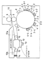
図1に本発明の第1の実施形態を示す。図1は、筐体21の内部に画像形成装置とキャリア液除去装置を収納した湿式電子写真の構成図を示している。
【0013】
まず、画像形成装置について説明する。
【0014】
潜像保持体1は、導電性基体の上に有機系もしくはアモルファスシリコン系の感光層を設けた感光体ドラムである。この潜像保持体1は周知のコロナ帯電器もしくはスコロトロン帯電器2−1によって均一に帯電された後、画像変調されたレーザビームによる露光3−1を受け、表面に静電潜像が形成される。しかる後に、液体現像剤を収納する現像装置4−1によって静電潜像の可視像化が行われる。静電潜像に付着した液体現像剤もしくはトナーは、そのまま転写工程に至り、転写装置5によって用紙に転写されても良いが、ここでは引き続き第2帯電器2−2と第2レーザ露光3−2で第2の静電潜像を形成し、第1の現像装置4−1に収納されている液体現像剤とは異なる色の第2の現像剤を収納する第2現像装置4−2によってこれを現像する。従って、第2現像の後には、潜像保持体1上には2色のトナー像が形成されている。同様にして、第3、第4の現像が行われ、潜像保持体1にはフルカラーのトナー像が形成される。このトナー像は、転写装置5によって用紙に転写されるが、その際には直接用紙に転写しても良いし、図1に例示するように中間転写媒体6を介して用紙10に転写しても良い。潜像保持体1から中間転写媒体6への転写、および中間転写媒体6から用紙10への転写においては、いずれも電界による転写かもしくは圧力(及び熱)による転写のいずれかを用いることが出来る。液体現像剤は一般に室温で用紙に定着できるものも多いが、加圧ローラ7などを加熱して、熱による定着を行っても良い。
【0015】
前記液体現像剤は、キャリア液とトナー粒子とを具備している。トナー粒子は平均粒径が1μm程度、あるいはそれ以下であり、樹脂成分と着色剤成分とを含有した荷電粒子である。キャリア液はトナー粒子の分散媒であり、絶縁性で有機性の液体が使用される。通常アイソパーL、ノルパー12(いずれも商品名:エクソン化学社製)などの石油系絶縁性溶剤を使用する。
【0016】
このように液体現像剤を使用した場合、サブミクロンサイズの極めて微細なトナー粒子を用いることができるため高画質を実現できること、少量のトナー粒子で十分な画像濃度が得られるため経済的であるうえに印刷(例えばオフセット印刷)並みの質感を実現できること、比較的低温でトナー粒子を用紙に定着出来るため省エネルギーを実現できることなどの利点がある。
【0017】
一方、前述したようなキャリヤ液は、一般に、機体内の液体現像剤が存在するあらゆる場所で自然揮発により気化して蒸気が発生する。さらに、図1の潜像保持体1上、あるいは中間転写媒体6上、あるいは加圧ローラ7上、あるいは用紙10上から液体現像剤のキャリヤ液を熱によって蒸発させ除去しようとすれば、筐体21内にキャリヤ液揮発成分が相当量発生し、筐体内部に存在する空気と混合して飽和蒸気圧あるいはそれに近い濃度まで達するおそれがあり、例えば紙詰まりなど筐体21を開放する時などにのキャリア液揮発成分を含む混合ガスが筐体外部へ放出させないために、キャリヤ液揮発成分を回収するキャリア液除去装置を筐体21内に設置している。
【0018】
次に、このキャリア液除去装置について説明する。
【0019】
除去容器12は、筐体内部の混合ガスを導入する導入口12aと、除去容器12内の混合ガスを排出する排出口12bとを具備している。導入口12aは、中間転写媒体6近傍、加圧ローラ7近傍あるいは用紙10近傍などキャリア液揮発成分濃度が高くなる場所に開口を有することでキャリア液揮発成分の回収効率を高めることができる。また排出口は図1に示すように筐体21外部に接続するように設けても良いし、筐体内部に排出する構成としてもよい。
【0020】
また、図1においては排出口12bにファン、ブロアあるいはポンプなどの吸引装置を配置することで、混合ガスを吸引口12aから混合ガスを吸引し、排出口12bから排出する構成としてある。また、吸引口12a、排出口12bは必要に応じそれぞれ複数個設けても良い。
【0021】
さらに、導入口12aおよび排出口12bにはそれぞれ気相分離フィルター15,16が配置されており、キャリア液揮発成分や空気などの気相は気相分離フィルター15,16を通過し、後述する、サイクロデキストリン水溶液や水などの液体、包接化合物などの固体は気相分離フィルター15,16によって除去容器12内に留まる構造になっている。
【0022】
一方、本第1の実施形態においては、図示するように、除去容器12の底部にはキャリア液揮発成分を捕集する除去剤としてのサイクロデキストリン水溶液が収納されており、このサイクロデキストリン水溶液中に霧化器である超音波振動子13が配置されている。
【0023】
ここで、サイクロデキストリンについて説明する。サイクロデキストリンは環状の分子構造をしており、疎水性材料(石油系溶剤など)と接触するとその材料分子を環状の分子構造内に包接し、包接化合物を形成する。サイクロデキストリン自体は水に対して可溶性であるのに対し、包接化合物となると難溶性を示すため、サイクロデキストリン水溶液中において、包接化合物は白色の沈殿物となり、サイクロデキストリン水溶液と分離する。
【0024】
このようなサイクロデキストリン水溶液は、超音波振動子13などの霧化器によって除去容器12内に散布されると、導入口12aから導入されたキャリア液揮発成分との接触面積が大きくなる。サイクロデキストリン水溶液がキャリア液に接触すると反応し、包接化合物(固体)と水との2相になり、その自重で除去容器12底部に収納されたサイクロデキストリン水溶液中に落下し沈殿するか、気相分離フィルター15によって捕集される。すなわち除去容器内においてキャリア液揮発成分は捕集される。一方、混合ガス中からキャリア液揮発成分を除去した残留ガス(通常は空気)は、気相分離フィルターを通過し、筐体21の外部へ排出される。
【0025】
このようにして、混合ガス中からキャリア液揮発成分を除去することが可能になる。
【0026】
次に、継続的にキャリア液揮発成分の除去を行った場合について説明する。
【0027】
散布されたうちの未反応のサイクロデキストリン水溶液、および一部の反応生成された包接化合物(および水)は、導入口12aから排出口12bへ向かう混合ガス流によって、排出口12bに配置された気相分離フィルター15に捕集され、その自重によって下方に向かって流れ落ちる。例えば排出口12bに除去容器12に向かって勾配を設けるなどして、捕集されたサイクロデキストリン水溶液、包接化合物および水を、除去容器12に戻す。その結果、超音波振動子によるサイクロデキストリン水溶液の散布を継続すると、除去容器12の底部には、初期状態に比べ濃度の低下したサイクロデキストリン水溶液と、この水溶液中に沈殿する包接化合物が貯蔵された状態となる。
【0028】
この状態で超音波振動子を駆動させると、液体であるサイクロデキストリン水溶液のみが霧化して再散布され、キャリア液揮発成分の捕集に使用される。
【0029】
したがって、継続的にキャリア液揮発成分の除去を行うと活性炭などと同様に、サイクロデキストリン水溶液もキャリア液揮発成分の除去機能が低下し、所定量のキャリア液揮発成分を捕集した時点で交換が必要となる。
【0030】
活性炭でキャリア液揮発成分を捕集した場合、キャリア液揮発成分の除去前後において視覚的な変化は見られないが、サイクロデキストリン水溶液でキャリア液揮発成分を捕集した場合、前述したように包接化合物が白色であるため、サイクロデキストリン水溶液が白濁する。その白濁度合いによってキャリア液揮発成分の機能低下度合いを判断することが可能であり、所定の白色度合いになったときに、サイクロデキストリン水溶液を新たなものに入れ替えればよい。
【0031】
図1に示すように、サイクロデキストリン水溶液を超音波振動子で散布する場合、超音波振動子の主面(超音波を発振させる面)とサイクロデキストリン水溶液の液面との距離を10mm〜30mm程度にすることが好ましい。この範囲を外れると、超音波振動子から発振される超音波の周波数や強度、サイクロデキストリン水溶液の粘度(濃度)によって多少異なるが、サイクロデキストリン水溶液を霧化することができなくなる恐れがある。
【0032】
また、超音波振動子で散布を行う場合、サイクロデキストリン水溶液の濃度は5〜20wt%程度にすることが好ましい。サイクロデキストリン水溶液の濃度が20wt%を超えると粘度が高くなり、霧化することができなくなる恐れがあり、5wt%に満たないとキャリア液揮発成分を十分に捕集することができなくなる。
【0033】
また、サイクロデキストリン水溶液中には、防腐剤などの他の添加物を添加することも可能であるし、サイクロデキストリン水溶液の水温を挙げることによって粘度も低下させることが可能であると同時に細菌などの発生を防ぐことも可能である。
【0034】
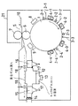
図2は第1の実施形態の変形例を示す湿式電子写真装置の概略構成図である。
【0035】
図2の湿式電子写真装置は、気相分離フィルター15あるいは16に水を供給するための給水口18および、供給された水を排出する排水口17が形成されている点で図1に示したものと異なる。
【0036】
気相分離フィルター16を長期間使用すると、包接化合物などが一部付着しフィルターの目詰まりが起こる恐れがあるが、給水口18から給水することで、水流によって付着した包接化合物を排水口17から排出し、フィルター16の水洗を行うことが可能となる。この水洗は、例えばサイクロデキストリン水溶液の交換時に行えばよい。
【0037】
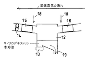
図3は、第1の実施形態の第2の変形例を示す図であり、除去容器12の拡大図である。
【0038】
図3においては除去容器12底部の両端部に凹部が設けられており、凹部間に傾斜が設けられている(図では右下がりの傾斜)。また、超音波振動子は傾斜の高い側(図では左側)に設けられた凹部に配置されている。
【0039】
このような構成にすると、包接化合物は傾斜下端部側に配置された凹部に堆積する。すなわち、超音波振動子13によって攪拌され、分散されたサイクロデキストリン水溶液中の包接化合物が沈殿すると、傾斜を伝って傾斜下端部側に配置された凹部に集まる。傾斜下端では超音波振動子から発振された超音波の音圧が小さいので、一度傾斜下端部に堆積した包接化合物は超音波振動子を駆動しても沈殿した状態でいる。
【0040】
前述したように超音波振動子による霧化はサイクロデキストリン水溶液の粘度が高まると困難になるが、このようにすることで、包接化合物によるサイクロデキストリン水溶液の粘度上昇を抑制し、安定してサイクロデキストリン水溶液を霧化することが可能になる。
【0041】
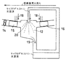
図4は、本発明の第2の実施形態に使用されるサイクロデキストリン除去装置を示す図である。なお、このサイクロデキストリン除去装置も図1に示す画像形成装置と共に筐体内に収納される。
【0042】
図4に示すキャリア液揮発成分除去装置は、噴射式の噴霧器20を霧化器として使用している。噴射式の噴霧器においては、サイクロデキストリンを飽和溶解させた水溶液の粘度程度では噴霧可能であるため、キャリア液揮発成分除去容器12中に高濃度のサイクロデキストリン水溶液を噴霧することが可能になる。
【0043】
また、サイクロデキストリン水溶液は、貯蔵タンク41タンク、噴霧器20、除去容器12、貯蔵タンク41の順で循環する機構になっている。
【0044】
貯蔵タンク41に収納されたサイクロデキストリン水溶液は、ポンプ42などにより噴霧器20に供給される。次に噴霧器20に供給されたサイクロデキストリン水溶液は霧化した状態で除去容器20に供給され、導入口12aから導入されたキャリア液揮発成分を捕集して包接化合物を生成する。さらに、未反応のサイクロデキストリン水溶液、包接化合物および水は、第1の実施の形態で説明したのと同様にして、自重により除去容器12の下方に移動し、除去容器12底部に形成された勾配に沿って貯蔵タンク41へ戻される。
【0045】
貯蔵タンク41は沈殿槽としても働き、貯蔵タンク41中では、包接化合物がサイクロデキストリン水溶液中で沈殿、分離するため、ポンプ42から噴霧器42へ包接化合物を含まずにサイクロデキストリン水溶液を供給することが可能なため、噴霧器の目詰まりを防止することができる。また、貯蔵タンク41を沈殿槽として機能させなくとも、循環系中に濾紙などを用いた濾過装置を配置することもできる。また、貯蔵タンク41を沈殿槽として機能させた上で、さらに濾過装置を付加しても良い。
【0046】
このようにして貯蔵タンク41中の包接化合物によって白濁した水溶液の白色度合いを基準に、キャリア液揮発成分の捕集程度を視認することが可能になり、ひいてはサイクロデキストリン水溶液のキャリア液揮発成分の除去能を確認することが可能になる。
【0047】
貯蔵タンク41内に収納されるサイクロデキストリン水溶液は、前述したように飽和濃度にまで高めたものも使用できるが、さらにサイクロデキストリンを貯蔵タンク41内に添加し、貯蔵タンク41内においては飽和量を超えるサイクロデキストリンを含有させておくこともできる。すなわち、貯蔵タンクを沈殿槽として機能させる、あるいは濾過装置を配置することで、飽和量を超えるサイクロデキストリンは貯蔵タンク41内で沈殿あるいは濾過され、噴霧器20には水溶液のみが供給されるため、噴霧器を目詰まりさせることなく霧化させることが可能である。
【0048】
前述したように、キャリア液揮発成分の除去を続けると、サイクロデキストリン水溶液の濃度が低下するが、貯蔵タンク41中に飽和量以上のサイクロデキストリンを含有させると、噴霧するサイクロデキストリン水溶液の濃度を長期間維持することができ、ひいてはサイクロデキストリン水溶液の交換頻度を少なくすることができる。
【0049】
【発明の効果】
以上説明したように本発明によれば、キャリア液除去装置を備えた湿式電子写真装置において、キャリア液除去剤の交換の目安を視認によって判断することが可能になる。
【図面の簡単な説明】
【図1】本発明の湿式電子写真装置の第1の実施形態を示す概略構成図。
【図2】第1の実施形態の変形例を示す湿式電子写真装置の概略構成図。
【図3】第2の実施形態を示すキャリア液除去装置の構成図。
【図4】本発明の第2の実施形態に用いるキャリア液除去装置の構成図。
【符号の説明】
1…静電潜像保持体
2…帯電器
3…レーザ露光
4…現像器
5…転写装置
6…中間転写ローラ
7…加圧ローラ
8…クリーナー
9…キャリア液乾燥装置
10…用紙
12…除去容器
12a…導入口
12b…排出口
13…超音波振動子
14…ファン
15、16…気相分離フィルター
17…排水口
18…給水口
20…霧化器
21…筐体[0001]
TECHNICAL FIELD OF THE INVENTION
The present invention relates to a wet electrophotographic apparatus, and more particularly to a wet electrophotographic apparatus provided with a carrier liquid removing device for collecting and removing a volatile carrier liquid.
[0002]
[Prior art]
An electrophotographic apparatus using a liquid developer has an advantage that cannot be realized by a dry electrophotographic apparatus, and its value is being reviewed in recent years. For example, the liquid developer is obtained by dispersing toner particles in a carrier liquid, so that extremely fine submicron-sized toner particles can be used, so that high image quality can be realized. In addition to being economical because image density can be obtained, it is possible to realize a texture similar to that of printing (for example, offset printing), and to realize energy saving because toner particles can be fixed on paper at a relatively low temperature. The main advantage is.
[0003]
On the other hand, conventional liquid developer wet electrophotography has some essential problems, which have long allowed the sole use of dry technology.
[0004]
For example, a high-resistance or insulating liquid must be used as the carrier liquid, and a petroleum-based solvent must be used as the carrier liquid. This petroleum-based solvent has high volatility and emits an odor, so that it cannot be used in living rooms such as offices.
[0005]
Various treatments of a highly volatile carrier liquid have been conventionally performed. For example, in Japanese Patent Application Laid-Open No. 48-82835, liquefaction and recovery are performed by suctioning the carrier liquid vapor inside the housing. Release to the outside of the housing is suppressed. However, a method of liquefying and recovering the carrier liquid vapor by cooling is adopted, and in this case, in order to cool the carrier liquid, the steam mixed with the carrier liquid vapor also needs to be cooled at the same time, Poor recovery efficiency of carrier liquid vapor. In addition to the liquefaction method, there is also a method of recovering by adsorbing the carrier liquid vapor onto a collecting agent such as activated carbon.However, activated carbon has good initial short-term recovery characteristics, but after that period, After that, the recovery characteristics are rapidly reduced, and it is difficult to recover the carrier liquid vapor stably, or when the activated carbon is used as a collecting agent, the recovered amount of the carrier liquid is not visually recognized. Therefore, there is a problem that it is difficult to estimate the replacement of the collecting agent.
[0006]
[Problems to be solved by the invention]
As described above, in a conventional wet electrophotographic apparatus, for example, the removal and removal of the volatile component of the carrier liquid is performed using a removing agent such as activated carbon. There was a problem of not knowing.
[0007]
The present invention has been made in view of such a problem, and an object of the present invention is to provide a wet electrophotographic apparatus provided with a carrier liquid removing device capable of easily determining a guide for replacing a removing agent.
[0008]
[Means for Solving the Problems]
A wet electrophotographic apparatus according to the present invention includes an electrostatic latent image holding member, a carrier liquid that forms an electrostatic latent image on the latent image holding member, and a toner liquid having the electrostatic latent image dispersed in the carrier liquid. An image forming apparatus for developing with a liquid developer provided; a housing for housing the electrostatic latent image holder and the image forming apparatus; and a carrier liquid removal for removing a carrier liquid volatile component generated by volatilization in the housing. The carrier liquid removing device is characterized in that the carrier liquid removing device is provided with an atomizer for spraying a cyclodextrin aqueous solution as a removing agent in a gas containing the carrier liquid volatile component.
[0009]
The carrier liquid removing device includes a removal container having an inlet for introducing a gas containing the volatile component of the carrier liquid, and an outlet for discharging a residual gas from which the volatile component of the carrier liquid has been removed, the suction port, and the exhaust port. A gas phase separation filter disposed at an outlet; and the atomizer for spraying a cyclodextrin aqueous solution into the removal container.
[0010]
The aqueous cyclodextrin solution may be stored at the bottom of the removal container, and the atomizer including an ultrasonic vibrator may be disposed in the aqueous cyclodextrin solution.
[0011]
The wet electrophotographic apparatus of the present invention forms an electrostatic latent image on an electrostatic latent image holding member, and forms the electrostatic latent image with a liquid developer including a carrier liquid and toner particles dispersed in the carrier liquid. An image forming apparatus for developing; a housing for housing the electrostatic latent image holder and the image forming apparatus; and a carrier liquid removing apparatus for removing a carrier liquid volatile component generated by volatilization of the carrier liquid from the housing. Wherein the carrier liquid removing device comprises: a removing container having an inlet for introducing the mixed gas and an outlet for discharging a residual gas from which the carrier liquid volatile component has been removed; and An atomizer for spraying a cyclodextrin-containing aqueous solution that forms a solid clathrate upon contact with the carrier liquid, and the unreacted cycle recovered in the liquid removal container. Separating means for separating a dextrin solution from the solid component, wherein the circulating and re-spraying the aqueous solution separated by the separating means to the atomizer.
[0012]
BEST MODE FOR CARRYING OUT THE INVENTION
FIG. 1 shows a first embodiment of the present invention. FIG. 1 is a configuration diagram of a wet electrophotography in which an image forming apparatus and a carrier liquid removing apparatus are housed inside a
[0013]
First, the image forming apparatus will be described.
[0014]
The latent image carrier 1 is a photosensitive drum having an organic or amorphous silicon photosensitive layer provided on a conductive substrate. The latent image holding member 1 is uniformly charged by a well-known corona charger or scorotron charger 2-1 and then exposed to an image modulated laser beam 3-1 to form an electrostatic latent image on the surface. You. Thereafter, the electrostatic latent image is visualized by the developing device 4-1 containing the liquid developer. The liquid developer or toner adhering to the electrostatic latent image may be directly transferred to a transfer process by the
[0015]
The liquid developer includes a carrier liquid and toner particles. The toner particles have a mean particle size of about 1 μm or less, and are charged particles containing a resin component and a colorant component. The carrier liquid is a dispersion medium of toner particles, and an insulating and organic liquid is used. Usually, a petroleum-based insulating solvent such as Isopar L and Norpar 12 (both trade names: manufactured by Exxon Chemical Co., Ltd.) is used.
[0016]
When a liquid developer is used as described above, it is possible to use very fine toner particles having a submicron size, so that high image quality can be realized, and it is economical because a sufficient image density can be obtained with a small amount of toner particles. (E.g., offset printing), and the toner particles can be fixed on the paper at a relatively low temperature, so that energy can be saved.
[0017]
On the other hand, the carrier liquid as described above is generally vaporized by natural volatilization in any place where the liquid developer exists in the inside of the machine to generate steam. Further, if the carrier liquid of the liquid developer is to be removed by heat from the latent image holding member 1 in FIG. 1, the
[0018]
Next, the carrier liquid removing device will be described.
[0019]
The
[0020]
In FIG. 1, a suction device such as a fan, a blower, or a pump is disposed at the
[0021]
Further, gas-phase separation filters 15 and 16 are disposed at the inlet 12a and the
[0022]
On the other hand, in the first embodiment, as shown in the drawing, a cyclodextrin aqueous solution as a remover for collecting volatile components of the carrier liquid is stored at the bottom of the
[0023]
Here, cyclodextrin will be described. Cyclodextrin has a cyclic molecular structure, and when it comes into contact with a hydrophobic material (such as a petroleum-based solvent), the material molecule is included in the cyclic molecular structure to form an inclusion compound. Cyclodextrin itself is soluble in water, whereas it becomes sparingly soluble when used as an inclusion compound. Therefore, the inclusion compound becomes a white precipitate in the aqueous cyclodextrin solution and separates from the aqueous cyclodextrin solution.
[0024]
When such a cyclodextrin aqueous solution is sprayed into the
[0025]
Thus, it becomes possible to remove the volatile component of the carrier liquid from the mixed gas.
[0026]
Next, a case where the volatile component of the carrier liquid is continuously removed will be described.
[0027]
The unreacted aqueous cyclodextrin solution and a part of the clathrate compound (and water) produced by the spraying were disposed at the
[0028]
When the ultrasonic vibrator is driven in this state, only the cyclodextrin aqueous solution, which is a liquid, is atomized and re-sprayed, and is used for collecting volatile components of the carrier liquid.
[0029]
Therefore, if the volatile component of the carrier liquid is continuously removed, the function of removing the volatile component of the carrier liquid in the aqueous cyclodextrin solution is reduced as in the case of activated carbon, and the replacement is performed when a predetermined amount of the volatile component of the carrier liquid is collected. Required.
[0030]
When the volatile component of the carrier liquid is collected with activated carbon, there is no visual change before and after the removal of the volatile component of the carrier liquid, but when the volatile component of the carrier liquid is collected with the aqueous cyclodextrin solution, the inclusion is performed as described above. Since the compound is white, the aqueous cyclodextrin solution becomes cloudy. The degree of functional deterioration of the volatile component of the carrier liquid can be determined based on the degree of white turbidity. When the degree of whiteness reaches a predetermined level, the aqueous cyclodextrin solution may be replaced with a new one.
[0031]
As shown in FIG. 1, when the aqueous cyclodextrin solution is sprayed with an ultrasonic vibrator, the distance between the main surface of the ultrasonic vibrator (the surface that oscillates ultrasonic waves) and the liquid surface of the cyclodextrin aqueous solution is about 10 mm to 30 mm. Is preferable. Outside this range, the cyclodextrin aqueous solution may not be able to be atomized, although it may vary slightly depending on the frequency and intensity of the ultrasonic wave oscillated from the ultrasonic transducer and the viscosity (concentration) of the cyclodextrin aqueous solution.
[0032]
When spraying with an ultrasonic vibrator, the concentration of the cyclodextrin aqueous solution is preferably set to about 5 to 20 wt%. If the concentration of the cyclodextrin aqueous solution exceeds 20% by weight, the viscosity increases, and there is a possibility that atomization cannot be achieved. If the concentration is less than 5% by weight, the volatile component of the carrier liquid cannot be sufficiently collected.
[0033]
In the cyclodextrin aqueous solution, it is also possible to add other additives such as a preservative, and it is possible to lower the viscosity by raising the water temperature of the cyclodextrin aqueous solution, and at the same time, to reduce bacteria and the like. It is also possible to prevent occurrence.
[0034]
FIG. 2 is a schematic configuration diagram of a wet electrophotographic apparatus showing a modification of the first embodiment.
[0035]
The wet electrophotographic apparatus of FIG. 2 is shown in FIG. 1 in that a
[0036]
If the gas-
[0037]
FIG. 3 is a diagram illustrating a second modification of the first embodiment, and is an enlarged view of the
[0038]
In FIG. 3, concave portions are provided at both ends of the bottom of the
[0039]
With such a configuration, the clathrate is deposited in the concave portion arranged on the side of the inclined lower end. That is, when the clathrate compound in the cyclodextrin aqueous solution which is stirred and dispersed by the
[0040]
As described above, atomization by an ultrasonic vibrator becomes difficult when the viscosity of the cyclodextrin aqueous solution increases, but by doing so, the increase in the viscosity of the cyclodextrin aqueous solution due to the inclusion compound is suppressed, and the cyclodextrin solution is stabilized. It becomes possible to atomize the dextrin aqueous solution.
[0041]
FIG. 4 is a diagram showing a cyclodextrin removing device used in the second embodiment of the present invention. The cyclodextrin removing device is also housed in a housing together with the image forming apparatus shown in FIG.
[0042]
The carrier liquid volatile component removing device shown in FIG. 4 uses an
[0043]
Further, the cyclodextrin aqueous solution is configured to circulate in the order of the storage tank 41 tank, the
[0044]
The aqueous cyclodextrin solution stored in the storage tank 41 is supplied to the
[0045]
The storage tank 41 also functions as a sedimentation tank. In the storage tank 41, since the clathrate is precipitated and separated in the cyclodextrin aqueous solution, the cyclodextrin aqueous solution is supplied from the pump 42 to the sprayer 42 without the clathrate. Therefore, clogging of the sprayer can be prevented. Further, even if the storage tank 41 does not function as a sedimentation tank, a filtration device using filter paper or the like can be arranged in the circulation system. In addition, the storage tank 41 may function as a sedimentation tank, and a filtering device may be further added.
[0046]
In this manner, it is possible to visually check the degree of collection of the volatile component of the carrier liquid based on the whiteness of the aqueous solution clouded by the clathrate in the storage tank 41, and thus the volatile component of the carrier liquid of the aqueous cyclodextrin solution. The removal ability can be confirmed.
[0047]
As the cyclodextrin aqueous solution to be stored in the storage tank 41, a solution having a saturated concentration increased as described above can be used. However, cyclodextrin is further added to the storage tank 41, and the saturation amount is reduced in the storage tank 41. More than one cyclodextrin may be included. That is, by making the storage tank function as a sedimentation tank, or by arranging a filtration device, cyclodextrin exceeding the saturation amount is precipitated or filtered in the storage tank 41, and only the aqueous solution is supplied to the
[0048]
As described above, the concentration of the cyclodextrin aqueous solution decreases as the removal of the volatile component of the carrier liquid continues. However, if the storage tank 41 contains a cyclodextrin at a saturation amount or more, the concentration of the cyclodextrin aqueous solution to be sprayed increases. For a long period, the exchange frequency of the cyclodextrin aqueous solution can be reduced.
[0049]
【The invention's effect】
As described above, according to the present invention, in a wet electrophotographic apparatus provided with a carrier liquid removing device, it is possible to visually determine a guide for replacing the carrier liquid removing agent.
[Brief description of the drawings]
FIG. 1 is a schematic configuration diagram showing a first embodiment of a wet electrophotographic apparatus according to the present invention.
FIG. 2 is a schematic configuration diagram of a wet electrophotographic apparatus showing a modification of the first embodiment.
FIG. 3 is a configuration diagram of a carrier liquid removing apparatus according to a second embodiment.
FIG. 4 is a configuration diagram of a carrier liquid removing device used in a second embodiment of the present invention.
[Explanation of symbols]
REFERENCE SIGNS LIST 1 electrostatic latent image holder 2 charger 3 laser exposure 4 developing
Claims (4)
前記静電潜像保持体及び画像形成装置を収容する筐体と、
この筐体内で揮発して発生したキャリア液揮発成分を除去するキャリア液除去装置とを有する湿式電子写真装置において、
前記キャリア液除去装置は、前記キャリア液揮発成分を含有する気体中にサイクロデキストリン水溶液を除去剤として散布する霧化器を具備することを特徴とする湿式電子写真装置。An image formed by forming an electrostatic latent image on the latent image holding member and developing the electrostatic latent image with a liquid developer including a carrier liquid and toner particles dispersed in the carrier liquid; A forming device;
A housing accommodating the electrostatic latent image holder and the image forming apparatus;
In a wet electrophotographic apparatus having a carrier liquid removing device for removing a carrier liquid volatile component generated by volatilization in the housing,
The wet electrophotographic apparatus, wherein the carrier liquid removing device includes an atomizer for spraying a cyclodextrin aqueous solution as a removing agent in a gas containing the carrier liquid volatile component.
前記キャリア液揮発成分を含有する気体を導入する導入口および、前記キャリア液揮発成分を除去した残存ガスを排出する排出口を有する除去容器と、
前記吸引口および前記排出口に配置された気相分離フィルターと、
前記除去容器内にサイクロデキストリン水溶液を散布する前記霧化器とを有することを特徴とする請求項1記載の湿式電子写真装置。The carrier liquid removing device,
An inlet for introducing a gas containing the carrier liquid volatile component, and a removal container having an outlet for discharging a residual gas from which the carrier liquid volatile component has been removed,
A gas phase separation filter arranged at the suction port and the discharge port,
The wet electrophotographic apparatus according to claim 1, further comprising: the atomizer for spraying a cyclodextrin aqueous solution into the removal container.
前記キャリア液除去装置は、
前記混合気体を導入する導入口および、前記キャリア液揮発成分を除去した残存ガスを排出する排出口を有する除去容器と、
この除去容器内に、前記キャリア液と接触して固体状の包接化合物を生成するサイクロデキストリンを含有する水溶液を散布する霧化器と、
前記液除去容器中で回収した未反応の前記サイクロデキストリン水溶液を固体成分から分離する分離手段と、
前記分離手段によって分離された水溶液を前記霧化器に循環して再散布することを特徴とする湿式電子写真装置。An image forming apparatus for forming an electrostatic latent image on an electrostatic latent image holding member and developing the electrostatic latent image with a liquid developer including a carrier liquid and toner particles dispersed in the carrier liquid; In a wet-type electrophotographic apparatus, comprising: a housing accommodating an electrostatic latent image holder and the image forming apparatus; and a carrier liquid removing device for removing a carrier liquid volatile component generated by volatilization of the carrier liquid from the inside of the housing.
The carrier liquid removing device,
An inlet for introducing the mixed gas, and a removal container having an outlet for discharging a residual gas from which the carrier liquid volatile component has been removed,
An atomizer for spraying an aqueous solution containing cyclodextrin that generates a solid clathrate in contact with the carrier liquid,
Separation means for separating the unreacted aqueous cyclodextrin solution recovered in the liquid removal container from solid components,
A wet electrophotographic apparatus, wherein the aqueous solution separated by the separating means is circulated to the atomizer and re-sprayed.
Priority Applications (3)
| Application Number | Priority Date | Filing Date | Title |
|---|---|---|---|
| JP2000333923A JP3577458B2 (en) | 2000-10-31 | 2000-10-31 | Wet electrophotographic equipment |
| US09/984,493 US6615012B2 (en) | 2000-10-31 | 2001-10-30 | Electrophotographic apparatus using liquid developer |
| US10/427,949 US6804487B2 (en) | 2000-10-31 | 2003-05-02 | Electrophotographic apparatus |
Applications Claiming Priority (1)
| Application Number | Priority Date | Filing Date | Title |
|---|---|---|---|
| JP2000333923A JP3577458B2 (en) | 2000-10-31 | 2000-10-31 | Wet electrophotographic equipment |
Publications (2)
| Publication Number | Publication Date |
|---|---|
| JP2002139917A JP2002139917A (en) | 2002-05-17 |
| JP3577458B2 true JP3577458B2 (en) | 2004-10-13 |
Family
ID=18809924
Family Applications (1)
| Application Number | Title | Priority Date | Filing Date |
|---|---|---|---|
| JP2000333923A Expired - Lifetime JP3577458B2 (en) | 2000-10-31 | 2000-10-31 | Wet electrophotographic equipment |
Country Status (2)
| Country | Link |
|---|---|
| US (2) | US6615012B2 (en) |
| JP (1) | JP3577458B2 (en) |
Families Citing this family (6)
| Publication number | Priority date | Publication date | Assignee | Title |
|---|---|---|---|---|
| JP3641580B2 (en) * | 2000-09-29 | 2005-04-20 | 株式会社東芝 | Wet image forming device |
| JP2004181672A (en) * | 2002-11-29 | 2004-07-02 | Fuji Photo Film Co Ltd | Image recorder |
| US6934486B2 (en) * | 2003-06-10 | 2005-08-23 | Hewlett-Packard Development Company, L.P. | Hard imaging device vapor removal systems, hard imaging devices, and hard imaging methods |
| KR100533836B1 (en) * | 2004-04-28 | 2005-12-07 | 삼성전자주식회사 | An oxidation catalyst unit and a wet-type electrophotographic image forming apparatus comprising oxidation catalyst unit |
| US9421793B2 (en) * | 2014-06-26 | 2016-08-23 | Cellresin Technologies, Llc | Electrostatic printing of cyclodextrin compositions |
| CN110431491B (en) | 2017-04-05 | 2022-11-18 | 惠普深蓝有限责任公司 | Method and apparatus for collecting liquid carrier from vapor of printing system |
Family Cites Families (2)
| Publication number | Priority date | Publication date | Assignee | Title |
|---|---|---|---|---|
| DE3045485A1 (en) * | 1980-12-03 | 1982-07-08 | Hoechst Ag, 6000 Frankfurt | METHOD AND DEVICE FOR THERMALLY FIXING TONER IMAGES |
| JPS63143926A (en) | 1986-12-05 | 1988-06-16 | Sumikin Osaka Plant Koji Kk | Deodorizing method |
-
2000
- 2000-10-31 JP JP2000333923A patent/JP3577458B2/en not_active Expired - Lifetime
-
2001
- 2001-10-30 US US09/984,493 patent/US6615012B2/en not_active Expired - Fee Related
-
2003
- 2003-05-02 US US10/427,949 patent/US6804487B2/en not_active Expired - Fee Related
Also Published As
| Publication number | Publication date |
|---|---|
| JP2002139917A (en) | 2002-05-17 |
| US6804487B2 (en) | 2004-10-12 |
| US20030228174A1 (en) | 2003-12-11 |
| US20020051656A1 (en) | 2002-05-02 |
| US6615012B2 (en) | 2003-09-02 |
Similar Documents
| Publication | Publication Date | Title |
|---|---|---|
| US5737674A (en) | Vapor control system for and a liquid electrographic system | |
| US8818231B2 (en) | Image forming apparatus | |
| JP3577458B2 (en) | Wet electrophotographic equipment | |
| US6011943A (en) | Ink delivery system for liquid electrophotographic printer | |
| KR100467607B1 (en) | Fuser of liquid type image forming system having carrier vapor dilution apparatus and liquid type image forming system using it | |
| JP4302632B2 (en) | System and method for recycling hydrocarbon carrier liquid | |
| JPH03137656A (en) | Image forming device | |
| JP2002108158A (en) | Wet electrophotographic equipment | |
| JPH06269632A (en) | Image forming device for electrophtography | |
| JP2000221787A (en) | Controller and control method for wet electrophotographic device | |
| JP3641580B2 (en) | Wet image forming device | |
| JPH08334984A (en) | Solvent gas removing device | |
| JPH02287571A (en) | Deodorizing device for wet development type electronic printer | |
| JP2002268393A (en) | Wet image forming device | |
| JPH03116162A (en) | Wet image forming device | |
| JP2001083807A (en) | Wet electrophotographic equipment | |
| KR100313866B1 (en) | Air circulation system of wet electrophotographic printer | |
| JP3455688B2 (en) | Wet electrophotographic equipment | |
| KR100230322B1 (en) | Image Forming Device | |
| JP3696109B2 (en) | Image forming apparatus, carrier processing apparatus and carrier processing method using liquid developer | |
| KR100322557B1 (en) | Ink circulating system for wet type electrophotographic printer | |
| KR200168975Y1 (en) | Developing apparatus of printer | |
| JP2002287519A (en) | Image forming apparatus, carrier processing apparatus and carrier processing method using liquid developer | |
| KR19990018459A (en) | Developer vapor recovery device of the image forming apparatus | |
| JPS59113473A (en) | cleaning equipment |
Legal Events
| Date | Code | Title | Description |
|---|---|---|---|
| A977 | Report on retrieval |
Free format text: JAPANESE INTERMEDIATE CODE: A971007 Effective date: 20040402 |
|
| TRDD | Decision of grant or rejection written | ||
| A01 | Written decision to grant a patent or to grant a registration (utility model) |
Free format text: JAPANESE INTERMEDIATE CODE: A01 Effective date: 20040706 |
|
| A61 | First payment of annual fees (during grant procedure) |
Free format text: JAPANESE INTERMEDIATE CODE: A61 Effective date: 20040712 |
|
| FPAY | Renewal fee payment (event date is renewal date of database) |
Free format text: PAYMENT UNTIL: 20080716 Year of fee payment: 4 |
|
| FPAY | Renewal fee payment (event date is renewal date of database) |
Free format text: PAYMENT UNTIL: 20090716 Year of fee payment: 5 |
|
| FPAY | Renewal fee payment (event date is renewal date of database) |
Free format text: PAYMENT UNTIL: 20090716 Year of fee payment: 5 |
|
| FPAY | Renewal fee payment (event date is renewal date of database) |
Free format text: PAYMENT UNTIL: 20100716 Year of fee payment: 6 |