JP3576816B2 - Method and apparatus for detecting when a digital television signal is accompanied by co-channel interfering analog television signals - Google Patents
Method and apparatus for detecting when a digital television signal is accompanied by co-channel interfering analog television signals Download PDFInfo
- Publication number
- JP3576816B2 JP3576816B2 JP17944798A JP17944798A JP3576816B2 JP 3576816 B2 JP3576816 B2 JP 3576816B2 JP 17944798 A JP17944798 A JP 17944798A JP 17944798 A JP17944798 A JP 17944798A JP 3576816 B2 JP3576816 B2 JP 3576816B2
- Authority
- JP
- Japan
- Prior art keywords
- signal
- digital television
- response
- television signal
- phase
- Prior art date
- Legal status (The legal status is an assumption and is not a legal conclusion. Google has not performed a legal analysis and makes no representation as to the accuracy of the status listed.)
- Expired - Fee Related
Links
Images


Classifications
-
- H—ELECTRICITY
- H04—ELECTRIC COMMUNICATION TECHNIQUE
- H04N—PICTORIAL COMMUNICATION, e.g. TELEVISION
- H04N5/00—Details of television systems
- H04N5/14—Picture signal circuitry for video frequency region
- H04N5/21—Circuitry for suppressing or minimising disturbance, e.g. moiré or halo
-
- H—ELECTRICITY
- H04—ELECTRIC COMMUNICATION TECHNIQUE
- H04N—PICTORIAL COMMUNICATION, e.g. TELEVISION
- H04N5/00—Details of television systems
- H04N5/44—Receiver circuitry for the reception of television signals according to analogue transmission standards
- H04N5/455—Demodulation-circuits
Description
【0001】
【発明の属する技術分野】
本発明はテレビジョン放送信号帯域内の高周波によってディジタルテレビジョン信号を伝送するディジタルテレビジョンに係り、特にディジタルテレビジョン信号が十分な振幅をもつ同一チャネルを干渉する(co−channel interferring) NTSC信号を伴う時期をディジタルテレビジョン受信機で検出する方法に関する。
【0002】
【従来の技術】
ATSC(Advanced Television Subcommittee)によって1995年9月16日に発表されたディジタルテレビジョン標準は、米国内のNTSC(National Television Subcommittee)アナログテレビジョン信号の無線放送に現在用いられているもののような6MHz帯域幅のテレビジョンチャネルのディジタルテレビジョン信号を伝送するための残留側波帯(vestigial sideband:VSB)信号の名前を規定している。NTSCアナログテレビジョン信号が放送される限り、あるNTSCアナログテレビジョン信号が受信中のディジタルテレビジョン信号に同一チャネル干渉を誘発する時期を受信機内でディジタルテレビジョン信号が検出し得るようにすることが有利である。前記ディジタルテレビジョン受信機は同一チャネル干渉が生じていると決定されると、この決定に応じてその動作モードを変更するように設計することにより、前記同一チャネル干渉の所望しない効果を減少させることができるが、これは通常コームフィルタによって行われていたものである。
【0003】
NTSC同一チャネル干渉を抑えるためにディジタルテレビジョン受信機で用いられるコームフィルタは、前記同一チャネル干渉が生じない場合には使用しない方がよいが、その理由はコームフィルタを使用しなければ、このコームフィルタを通過する多数の経路からジョンソン雑音(Johnson noise)が付加的に発生することを防止し得るためである。一般に、NTSCアナログテレビジョン信号から発生する同一チャネル干渉がディジタルテレビジョン信号を基底帯域にシンクロダイン(synchrodyning)させるためのシンボルデコーディング(symbol decoding)時に行われるデータスライシング(data slicing)動作に誤りを生じさせるほどの充分なエネルギーをもつ場合、同一チャネル干渉が実在すると見なす。1997年3月21日付けで出願された米国特許出願第08/821,944号の「Using video signals from auxiliary analog TV receivers for detecting NTSC interference in digital TV receivers」には、実質的な同一チャネル干渉が生じているか否かを決定し、これに応じてその動作モードを変更するように設計されることにより、同一チャネル干渉のような所望しない効果を減少させるディジタルテレビジョン受信機について記述されている。前記特許から基底帯域にディジタルテレビジョン信号をシンクロダインさせた後よりは、前記NTSC同一チャネル干渉を基底帯域にシンクロダインさせた後に、ディジタルテレビジョン受信機によるNTSC同一チャネル干渉を検出することがより容易であるのが分かる。
【0004】
1992年6月16日付で公布された米国特許第5,122,879号明細書の「Television sychronous receiver with phase shifter for reducing interference from a lower adjacent channel」には受信されたNTSC信号を同位相(in−phase)と直角位相(quadrature−phase)で同期的に検出するアナログテレビジョン受信機について記載されている。この受信機は高周波振幅器の応答を直接的に基底帯域にシンクロダインして、隣接した低いチャネルが像(Image)で現れるようにする。前記直角位相同期検出応答は500〜750kHz以上の全てのビデオ周波数で90°位相ずれが生じ、前記同位相同期検出応答と線形的に組み合わせられて前記受信されたNTSC信号の同期検出がなされる間に基底帯域に変換されたイメージ周波数成分を押さえる。前記米国特許5,122,879号には前記過程が750kHz以上のビデオ周波数成分までも無くしてしまうという事実については記述されていない。しかし、高周波信号の輝度の損失は腕時計に用いられるもののような小さいスクリーンテレビジョン受信機で許されることができる。
【0005】
現在のディジタルテレビジョン受信機は、多数の周波数変換を用いるように設計されるが、チャネル帯域以上の超高周波(Ultrahigh frequency:UHF)帯域における中間周波数への第1変換はテレビジョン放送で指定され、チャネル帯域以下の高周波(very high frequency:VHF)帯域における中間周波数への第2変換はテレビジョン放送で指定される。従って、像の抑制はこれ以上問題とならない。しかも、VSBディジタルテレビジョン信号の搬送波はチャネルエッジから僅か310kHzに位置するので、NTSC信号に比べて両側波帯(double sideband)成分が殆ど存在しない。
【0006】
【発明が解決しようとする課題】
本発明者は、同位相同期ビデオ検出応答と逆ヒルバート変換された(inverse−Hilvert−transformed)直角位相同期ビデオ検出応答を線形的に組み合わせる形の NTSC受信機はディジタルテレビジョン信号が十分な振幅をもつ同一チャネル干渉NTSC信号を伴う場合に、これを検出するための補助受信機として用いられるので、ディジタルテレビジョン信号の受信において重要であることを指摘している。前記直角位相同期ビデオ検出応答の逆ヒルバート変換を750kHz以下の周波数に調整すると、前記のような補助受信機は同一チャネルディジタルテレビジョン信号の人造雑像(artifacts)に反応しない。ディジタルテレビジョ ン信号の人造雑像を押さえれば、同一チャネル干渉NTSC信号のサイズが容易に測定される。
【0007】
【課題を解決するための手段】
本発明の一実施形態は、ディジタルテレビジョン信号が同一チャネル干渉NTSC信号を伴う時期をディジタルテレビジョン受信機で検出する方法を具現する。前記方法は次のような過程でなされる。まず、同一チャネル干渉NTSC信号のビデオ成分が基底帯域にシンクロダインされて前記ディジタルテレビジョン信号の第1人造雑像(アーチファクト)を含む同位相復調結果を生成し、前記ディジタルテレビジョン信号の第2人造雑像を含む直角位相復調結果を生成する。次に、前記同位相及び直角位相復調結果をそれぞれ数kHz以上の周波数で90゜の差をつけて位相シフトさせた後、線形的に組み合わせて前記ディジタルテレビジョン信号の第1及び第2人造雑像が取り除かれた線形組合せ結果を生成する。その後、前記線形組合せ結果の振幅が所定の値を超過しないか否かを検出して、前記ディジタルテレビジョン信号が十分な振幅をもつ同一チャネル干渉NTSC信号を伴う時期を表示する。
【0008】
本発明の他の実施形態は、十分な振幅をもつアナログテレビジョン信号がテレビジョン放送チャネルを占有する時間を検出するための回路を含むディジタルテレビジョン受信機を実現する。前記受信機は入力回路を備えるが、この入力回路はテレビジョン放送チャネルからこのテレビジョン放送チャネルを占有するアナログテレビジョン信号のビデオ信号部分を示す残留側波帯振幅変調信号を選択し、この選択された残留側波帯振幅変調信号を中間周波数信号に変換し、この中間周波数信号を増幅して、増幅された中間周波数信号を提供する。前記入力回路によって受信された前記残留側波帯振幅変調信号は残留側波帯とビデオ搬送波及び全側波帯(full sideband)を含む。
【0009】
ビデオシンクロダイン回路は前記ビデオ搬送波信号と関連し、このビデオ搬送波信号の直角位相の搬送波と関連した前記増幅された中間周波数を同期的に検出して同位相同期検出応答及び直角位相同期検出応答を生成する。本明細書で逆ヒルバート変換回路と命名される移相回路は、所定周波数以上の前記直角位相同期検出応答の全ての周波数成分を90°シフトさせて移相回路の応答を生成する。線形組合せ回路は前記同位相同期検出の応答と移相回路の応答を線形的に組み合わせて、前記受信された残留側波帯振幅変調信号の全側波帯と残留側波帯によって現れる前記ビデオ信号部分に応じて線形組合せ回路応答を再生する。前記線形組合せ回路の応答は現在受信中のテレビジョン放送チャネルを占有するディジタルテレビジョン信号の応答に反応しない。しきい検出器が前記受信機に含まれるが、このしきい検出器は第1線形組合せ回路の応答が所定のしきい値を超える時期を検出して、前記同一チャネルアナログテレビジョン信号が十分な振幅をもつ信号であることを示す。
【0010】
【発明の実施の形態】
以下、添付図面を参照して本発明を詳細に説明する。
図1はディジタルテレビジョン信号のみならずNTSCアナログテレビジョン信号を受信し得るテレビジョン受信機を示す。アンテナ1によって受信された無線テレビジョン放送信号は、適切に同調された無線周波数増幅器2によって増幅されて第1検出器3に送られる。前記無線周波数増幅器2と第1検出器3は、適切に同調されて周波数帯域内の互いに異なる位置に存在するチャネルのいずれか一つからディジタルテレビジョン信号を選択するためのチューナとしての機能を果たす。第1検出器3は超高周波(UHF0テレビジョン放送信号以上の周波数範囲にわたって同調可能な第1局部発振を提供する第1局部発振器と、第1局部発振を前記適切に同調された無線周波数増幅器2によって選択されたテレビジョン信号と混合して、前記選択されたテレビジョン信号を上向変換することによりUHFテレビジョン放送帯域内の割り当てられたチャネル周波数以上の周波数に位置する6MHz幅のUHF中間周波数帯域内のUHF中間周波数信号を生成する第1混合器とを含む。
【0011】
前記第1検出器3はNTSCオーディオ受信に用いられるUHF帯域中間周波数増幅器6へ前記UHF中間周波数信号を供給する。UHF中間周波数増幅器6の出力はNTSCオーディオ受信に用いられる第2検出器9に印加される。第2検出器9は、UHFテレビジョン放送帯域周波数以上の所定の周波数の第2局部発振を提供する第2局部発振器と、第2局部発振と前記UHF中間周波数増幅器6の出力を混合してVHFテレビジョン放送帯域内の割り当てられたチャネル周波数以下の周波数に位置するVHF中間周波数信号を生成する第2混合器とを含む。このVHF中間周波数信号はVHF中間周波数増幅器12に印加される。
【0012】
VHF中間周波数増幅器12の出力はインタキャリアサウンド検出器34に印加されるが、このインタキャリアサウンド検出器34は4.5MHzのインタキャリアサウンド中間周波数信号をインタキャリアサウンド中間周波数増幅器35へ供給する。インタキャリアサウンド中間周波数増幅器35はインタキャリアサウンド中間周波数信号を増幅し、前記増幅された信号を対称的に制限してFM検出器36へ印加する。FM検出器36は前記ディジタルテレビジョン受信機のアナログテレビジョン受信機部分の残りの構成部分へ供給される基底帯域複合信号(baseband composite signal)を再生する。前記残りの構成部分には一般に立体音響(stereophonic)デコーダ回路が含まれる。NTSCオーディオ信号がFMオーディオキャリアのみを通過させて中間周波数に変換する中間周波数増幅器6,12で狭帯域フィルタリングされて選択される場合には、前記インタキャリアサウンド検出器34は逓倍器(multiplier)にしてもよいが、この逓倍器は中間周波数増幅器(10または11)の出力に応答する狭帯域フィルタによって前記逓倍器で選択されるビデオ搬送波として前記中間周波数増幅器12の出力を逓倍する。NTSCオーディオ信号が「準並列(quasi−parallel)」サウンドを行うためにNTSオーディオ及びビデオ搬送波を共に通過させて中間周波数に変換させる前記中間周波数増幅器6,12でフィルタリングされて選択される場合には、前記インタキャリアサウンド検出器34は単純な整流器、或いは二乗器である。
【0013】
第1検出器3はNTSCビデオ受信及びATSC受信に共に用いられるUHF帯域中間周波数増幅器37へ高周波帯域信号を供給する。UHF中間周波数増幅器37内のSAW(surface−acoustic−wave)フィルタはATSCディジタルテレビジョン信号とNTSCビデオ信号に対する全ての中間周波数出力を決定し、NTSCオーディオ信号は拒否する。SAWフィルタはUHF中間周波数帯域に変換される6MHz幅のテレビジョン放送チャネルの残りのチャネルにわたって平坦な振幅出力を有し、自分の通過帯域にわたって線形の位相出力を有する。前記UHF中間周波数増幅器37内のSAWフィルタの前段には多重反射を最小化させる所定のソースインピダンスからSAWフィルタを駆動させるように設計されたトランジスタ増幅器が設けられる。前記所定のソースインピダンスを保持するためには前記トランジスタ増幅器の利得が固定の値を有しながら、前記SAWフィルタ内の挿入損失を克服するに充分なものが好ましい。UHF中間周波数増幅器37の出力はATSCディジタルテレビジョン受信及びNTSCビデオ受信に用いられる第2検出器38へ印加される。第2検出器38はUHFテレビジョン放送帯域周波数以上の所定の周波数の第2局部発振を提供する第2局部発振器と、第2局部発振とUHF中間周波数増幅器37の出力を混合してVHFテレビジョン放送帯域内の割り当てられたチャネル以下の周波数に位置するVHF中間周波数信号を生成する第2混合器とを含む。
【0014】
前記第2検出器38から出力される前記VHF中間周波数信号はVHF中間周波数増幅器41に印加されるが、このVHF中間周波数増幅器41は60dBまたはそれ以上の増幅を提供する調整利得(cotrolled−gain)トランジスタ増幅器段を含む。VHF中間周波数増幅器41はその出力信号レベルに応答する逆自動利得調整段(reverse automatic gain control(AGC))を備える。この逆AGCは自分の提供する利得の線形性のためのものである。前記RF増幅器2は中間周波数増幅器47の出力信号レベルに応じる遅延した逆自動利得調整段を備える。
【0015】
前記VHF中間周波数増幅器41の出力信号は基底帯域シンボルコードを検出するATSCシンボルコード検出器13に印加される。ATSCシンボルコード検出器13はデータ搬送波の残留側波帯振幅変調を検出するための同位相同期検出器を使用し、前記同期検出器にシンクロダイン信号を供給する制御発振器に対する自動周波数/位相制御(automaitc frequency and phase control:AFPC)を行うために直角位相同期検出器を使用する。前記同位相同期検出器はアナログ領域で動作し、アナログディジタル変換器14によってその出力が10ビットにディジタル化される。また、シンボルコード検出器13とその後続段のアナログ−ディジタル変換器14は、中間周波数増幅器47のVHF帯域出力を基底帯域以上の最終中間周波数帯域に変換させる第2検出器と、前記ディジタル化された第2検出器の出力を基底帯域にシンクダインするディジタルシンクロダイン回路で代替することができる。
【0016】
このような代替回路は1995年12月25日付で公布された米国特許のC.B.Patelの「Digital VSB detector with bandpass phase tracker,as for inclusion in an HDTV receiver」と、1995年8月20日付けで公布された米国特許第5,548,618号明細書の「Digital VSB detector with bandpass phase tracker using rader filters,as for use in an HDTV receiver」に記述されている。ディジタルテレビジョン信号が受信されると、パイロット信号の受信から由来したダイレクト信号が基底帯域で再生されるシンボルコードを伴ってパイロット搬送波検出器15によって検出され、ディジタルテレビジョンイネーブル信号を生成する。このディジタルテレビジョンイネーブル信号はディジタルテレビジョン受信機のディスプレイ部分を調節してNTSCテレビジョン像よりはディジタルテレビジョン像をディスプレイするようにする。前記パイロット搬送波検出器15は図1に示すようにディジタル入力信号に応じる形か、或いはシンボルコード検出器13から直接的に提供されるアナログ入力信号に応じる形のものである。
【0017】
図1はアナログ−ディジタル変換器14からシンボルデコーダ20に供給されるディジタル化された基底帯域シンボルコードを示している。前記シンボルデコーダ20は本発明者が1996年1月12日付けで米国特許出願第08/746,520号の「Digital television receiver with adaptive filter circuitry for suppressing NTSC co−channel interference」に詳細に記述されている。シンボルデコーダ20はシンボルデコーダ20の入力信号をデータスライシングして第1シンボルデコーダの出力を生成するデータスライサ21と、NTSC同一チャネル干渉信号を抑える応答信号をシンボルデコーダ20に提供するNTSC除去コームフィルタ22と、コームフィルタ22の出力をデータスライシングして、間違ったシンボルデコーダの出力を補正するデータスライサ24と、間違ったシンボルデコーダの出力を補正して第2シンボルデコーダの出力を生成する整合コームフィルタ24と、前記第1及び第2シンボルデコーダの出力のいずれか一つを信号デコーダ20によってディジタルテレビジョン受信機のトレリスデコーダ(trellis decoder)16に提供される最終的なシンボルデコーダ出力として選択するマルチプレクサ25とを含む。シンボルデコーダ初期化期間を除いた時間にNTSC同一チャネル干渉信号の受信される表示がない場合には、マルチプレクサ25が整合コームフィルタ24から第2シンボルデコーダの出力を選択してトレリスデコーダ16にシンボルデコーダ20の出力信号を提供する。
【0018】
前記マルチプレクサ25を、受信されたディジタルテレビジョンの信号にデータセグメント同期化及びフィールド同期化コードグループが現れる期間にテレビジョン受信機内のメモリから出力される理想的なシンボルデコーディング結果を提供するように変更することにより、前記シンボルデコーダ20の機能を向上させることができる。このように向上したシンボルデコーダは、本発明者が1997年4月15日付けで米国特許出願第08/839,691号「Digital television receiver with adaptive filter circuitry for suppressing NTSC co−channel interference」に詳細に記述されている。
【0019】
VHF中間周波数増幅器41の出力信号は、NTSCビデオ搬送波の変調を基底帯域にシンクロダインする回路46へ印加される。同位相同期検出器と直角位相同期検出器がNTSCビデオ搬送波の変調を基底帯域にシンクロダインするための前記回路46に用いられる。シンクロダインは基底帯域以上の最終の中間周波数帯域に変換された後、ディジタル領域内で行われて最終の中間周波数がディジタル化されうるようにする。また、基底帯域へのNTSCビデオ搬送波変調のシンクロダインはアナログ領域内で行われることができ、このような目的のために用いられる同位相同期検出器と直角位相同期検出器の出力はアナログ−ディジタル変換器を用いてそれぞれディジタル化されることができる。直角位相同期検出器の応答(Q)はNTSC信号の単一側波帯の成分(即ち、750kHz以上の成分)と同位相同期検出器の応答(I)に現れるディジタルテレビジョン信号の人造雑音のヒルバート変換である。前記直角位相同期検出器の応答(Q)によって提供されるヒルバート変換は位相シフトされ、逆ヒルバート変換回路47によって全ての周波数(応答のない一番低い周波数を除いた)で90°遅れを提供する。
【0020】
加算と減算は線形的に組み合わせられる選択的な形でなされる。線形組合せ器47,48のいずれか一方は加算器となり、他方は減算器となる。回路47の逆ヒルバート変換出力は線形組合せ器48内の同位相同期検出器の出力と線形的に組み合わせられてアナログテレビジョン受信機回路の残りの部分に提供されるためのレベルに補正されるようにブーストされた高周波数をもつ複合ビデオ信号を生成する。基底帯域複合ビデオ信号と関連して、前記残りの部分には同期分離回路、カラー信号再生回路及び4:3画面比のNTSC画像をディジタルテレビジョン像をディスプレイする16:9画面に表示し得るように変換させる回路が含まれる。
【0021】
回路47の逆ヒルバート変換出力は、線形組合せ器49でシンクロダイン回路46の同位相基底帯域出力(I)と線形的に組み合わせられて750kHz以上をカットオフする輝度信号を生成するが、この輝度信号にはディジタルテレビジョン人造雑音がない。線形組合せ器48、49がそれぞれ加算器と減算器であるか、それとも線形組合せ器48、49がそれぞれ減算器と加算器であるかは、前記直角位相同期検出器の動作を同位相同期検出の動作を進ませるか遅らせるかによって決定される。
【0022】
図1は1MHzのカットオフ周波数をもつ低域通過フィルタ50によってフィルタリングされた後、ディジタルテレビジョン信号の受信動作がなされる間のNTSC同一チャネル干渉信号のエネルギーを表示するために、二乗器(squarer)31によって二乗される前記線形組合せ器49から出力される帯域制限された輝度信号を示している。前記二乗器31は乗数(multiplier)と被乗数(multiplicand)で信号を受信するディジタル逓倍器から構成されることができるが、ROM(read only memory)で具現することがさらに実用的である。二乗器31の出力信号はディジタルテレビジョン信号受信時のNTSC同一チャネル干渉信号のエネルギーを表示する。
【0023】
ディジタルしきい検出器32は補正されていない誤りをデータスライサ21に流入させるのに不充分なNTSC同一チャネル干渉信号より低いしきい値を前記NTSC同一チャネル干渉信号のエネルギーが超過するほど充分大きい時期を決定する。しきい検出器31の出力はマルチプレクサ制御回路33に印加される。マルチプレクサ制御回路33はシンボルデコーダ20の出力信号として提供される最終シンボルデコーダの出力を決定する第1及び第2シンボルデコーダの出力をマルチプレクサ25が選択する動作を制御する。マルチプレクサ制御回路33はマルチプレクサ25がシンボルデコーダ初期化期間に第1シンボルデコーダの出力をシンボルデコーダ20の出力回路として選択するように制御する。他の期間には前記マルチプレクサ制御回路33は前記しきい検出器32の出力がNTSC同一チャネル干渉信号が補正されていない誤りをデータスライサ21の動作に流入するようにするに不充分であることを現す間、前記マルチプレクサ25がシンボルデコーダ20の出力信号として第1シンボルデコーダの出力を選択するように制御し、そうでない場合にはマルチプレクサ25をしてシンボルデコーダ20の出力信号として第2シンボルデコーダの出力を選択させるように制御する。
【0024】
図2は線形組合せ器49の出力を二乗器31によって二乗せず、ディジタルしきい検出器32に提供するために図1の装置を変形した形を示す。線形組合せ器49の出力は本質的に最大750kHzの基底帯域輝度信号なので、いつも同じ極性を有する。従って、二乗器31を省略することができ、ディジタルしきい検出器32はディジタルしきい検出器032の所定のしきい値の二乗根に相当する所定のしきい値をもつディジタルしきい検出器32で代替することができる。即ち、ディジタルしきい検出器32の所定のしきい値はディジタルしきい検出器032の所定のしきい値の二乗になる。
【0025】
図1及び図2のテレビジョン受信機において、低域通過フィルタ50が含まれることにより、逆ヒルバート変換回路47に対する要求事項を緩和させるが、これは低域通過フィルタ50のカットオフ周波数以上の周波数部分のディジタルテレビジョン人造雑像を抑えるために、前記周波数部分には正確に90°の遅れが提供される必要がないからである。逆ヒルバート変換回路47が4.2MHzの周波数に正確に90°の遅れを提供する場合、前記低域通過フィルタ50をストレート挿入連結(straight−through connection)で代替することができる。逆ヒルバート変換フィルタ47の出力を線形組合せ器48でシンクロダイン回路46の同位相基底低域出力(I)と組み合わせて複合ビデオ信号を高周波数にブーストするにおいて、前記逆ヒルバート変換回路47が4.2MHzまでの周波数に対して正確に90°の遅れを提供する必要はないが、これは遅れの誤りが酷くない場合に正確でない遅れを伴う複合ビデオ信号の高周波数のロールオフ(roll−off)を補償するためにビデオピーキング回路(video peaking circuitry)が用いられることができるからである。
【0026】
図3は図1及び図2のテレビジョン受信機の変形例を示す。図3において、逆ヒルバート変換回路47がシンクロダイン回路46の直角位相基底帯域応答Qをシフトさせて線形組合せ器48,49に印加する代わりに、逆ヒルバート変換回路51がシンクロダイン回路46の直角位相基底帯域応答Qをシフトさせて線形組合せ器48に印加し、他の逆ヒルバート変換回路49がシンクロダイン回路46の直角位相基底帯域応答Qをシフトさせて線形組合せ器49に印加する。逆ヒルバート変換回路51は0.5MHz〜4.2MHzの周波数に正確に90°の遅れを提供して前記複合ビデオ信号のスペクトル応答を最適化させるが、0.5MHz以下の周波数に90°の遅れを提供する必要はない。これにより、最高4.2MHzの周波数に90°の遅れを提供するに必要な高いディジタルサンプリング比で0.5MHz以下の周波数に90°の遅れを提供するに必要な多くのタップFIR(finite−impulse−response)フィルタが不要となる。前記高いディジタルサンプリング比は最高4.2MHzの周波数に90°の遅れを提供するのにも必要である。低域通過フィルタ50を使用するので、逆ヒルバート変換回路52は最高1.0MHzまでの周波数にのみ正確に90°の遅れを提供すべきである。
【0027】
逆ヒルバート変換回路52はNTSC走査線比(scan line rate)以下で0.5MHz以下の周波数に90°の遅れを提供する。このような要求条件は逆ヒルバート変換回路51に用いられるディジタルサンプリング比より4倍低い1/10のディジタルサンプリング比で充足されることができ、逆ヒルバート変換回路52内におけるFIRフィルタリングのために差別的に遅れたサンプリングを提供するための一時的な貯蔵に対する必要性を減らす。低域通過フィルタ50は0.5MHz以下の低いカットオフ周波数を持たせて、逆ヒルバート変換回路52で用いられる前記1/10ディジタルサンプリング比が逆ヒルバート変換回路51で用いられるディジタルサンプリング比より8倍低くなるように設計することができる。また、低域通過フィルタ50のカットオフ周波数をもう1回二等分するか或いは数回二等分して前記逆ヒルバート変換回路52で用いられる1/10ディジタルサンプリング比が逆ヒルバート変換回路51で用いられるディジタルサンプリング比の1/10となるようにすることができる。
【0028】
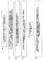
図4は図1のテレビジョン受信機によって行われる動作方法を示す流れ図である。初期段階S0ではビデオ信号部分をもった同一チャネル干渉アナログテレビジョン信号を時々伴うディジタルテレビジョン信号を受信し、このようなディジタルテレビジョン信号受信動作は図1のテレビジョン受信機の構成要素1,2,3,37,38,41によって行われる。シンクロダイン回路46はS1段階を行うが、この段階S1では同一チャネル干渉アナログテレビジョン信号のビデオ信号部分を基底帯域にシンクロダインしてディジタルテレビジョン信号の第1人造雑音を含む同位相復調結果を生成し、ディジタルテレビジョン信号の第2人造雑音を含む直角位相復調結果を生成する。逆ヒルバート変換回路47はS2段階を行うが、この段階S2では750kHz以下の所定の周波数範囲内の周波数で前記同位相及び直角位相復調結果を90゜の差をつけて位相シフトさせる。
【0029】
線形組合せ器49はS3段階を行うが、この段階S3では前記所定の周波数範囲内の周波数で90゜の差をつけて位相シフトされた同位相及び直角位相復調結果を線形的に組み合わせて、前記所定の周波数範囲内のディジタルテレビジョン信号の第1及び第2人造雑音が取り除かれた組合せ結果を生成する。(低域通過フィルタ50は前記所定の周波数範囲の上限を決定する)二乗器31はS4段階を行うが、この段階S4では前記線形組合せ結果を二乗する。ディジタルしきい検出器32は最終段階S5を行うが、この段階S5では前記線形組合せの結果を二乗した結果が前記所定値の二乗を超過するか否かを検出して、ディジタルテレビジョン信号が十分な振幅をもつ同一チャネル干渉アナログテレビジョン信号を伴うかを決定する。
【0030】
図5は図4のテレビジョン受信機によって行われる動作方法を示した流れ図で、逆ヒルバート変換回路47によって行われる段階S2が図4と異なるが、図5の段階S2’で750kHz以下の所定の周波数範囲内の周波数で直角位相復調結果を90°位相シフトさせる。
図6は図2のテレビジョン受信機によって行われる動作方法を示す流れ図である。図6に示した方法も図4のS0,S1,S2,S3段階と同一の段階を利用する。図1のテレビジョン受信機の二乗器31によって行われる二乗遂行段階S4は、図2のテレビジョン受信機の動作では省略される。図1のテレビジョン受信機のディジタルしきい検出器32によって行われるS5段階は、図2のテレビジョン受信機の動作ではS5’段階で代替されるが、この段階(S5’)で所定の周波数範囲内の線形組合せ結果の振幅が所定値を超過するかを検出して、ディジタルテレビジョン信号が十分な振幅をもつ同一チャネル干渉アナログテレビジョン信号を伴う時期を表す信号を生成する。この段階(S5’)は図2のテレビジョン受信機のディジタルしきい検出器32によって行われる。
【0031】
図7は図3のテレビジョン受信機によって行われる動作方法を示す流れ図で、逆ヒルバート変換回路47によって行われる図4のS2段階が図7のS2’段階と異なる。この段階(S2’)では750kHz以下の所定の周波数範囲内の周波数で直角位相復調結果を90°位相シフトさせる。
【図面の簡単な説明】
【図1】NTSCアナログテレビジョン信号とディジタルテレビジョン信号が受信でき、ディジタルテレビジョン信号内の同一チャネル干渉NTSCアナログテレビジョン信号の存在を検出するための本発明の方法を用いるテレビジョン受信機の構成図である。
【図2】NTSCアナログテレビジョン信号とディジタルテレビジョン信号が受信でき、ディジタルテレビジョン信号内の同一チャネル干渉NTSCアナログテレビジョン信号の存在を検出するための本発明の方法を用いるテレビジョン受信機の構成図である。
【図3】図1及び図2のテレビジョン受信機の変形例を示す構成図である。
【図4】本発明の一の実施形態によってディジタルテレビジョン信号が十分な振幅をもつ同一チャネル干渉NTSC信号を伴う時期をディジタルテレビジョン受信機で検出する方法を示す流れ図である。
【図5】本発明の他の実施形態による図4と同様の流れ図である。
【図6】本発明の他の実施形態による図4と同様の流れ図である。
【図7】本発明の他の実施形態による図4と同様の流れ図である。[0001]
TECHNICAL FIELD OF THE INVENTION
The present invention relates to a digital television that transmits a digital television signal by using a high frequency within a television broadcast signal band, and particularly to a digital television signal that is transmitted. Enough amplitude The present invention relates to a method for detecting in a digital television receiver when there is a co-channel interfering NTSC signal.
[0002]
[Prior art]
The Digital Television Standard, published on September 16, 1995 by the Advanced Television Subcommittee (ATSC), is a 6 MHz band such as that currently used for wireless broadcasting of National Television Subcommittee (NTSC) analog television signals in the United States. It defines the name of a vestigial sideband (VSB) signal for transmitting digital television signals of a wide television channel. As long as an NTSC analog television signal is broadcast, it may be possible for the digital television signal to be able to detect in a receiver when an NTSC analog television signal induces co-channel interference with a receiving digital television signal. It is advantageous. Reducing the undesirable effects of the co-channel interference by designing the digital television receiver to change its mode of operation in response to the determination that co-channel interference is occurring; Which is what was normally done by comb filters.
[0003]
The comb filter used in a digital television receiver to suppress NTSC co-channel interference should not be used if the co-channel interference does not occur. This is because Johnson noise can be prevented from being additionally generated from a large number of paths passing through the filter. Generally, co-channel interference generated from an NTSC analog television signal causes an error in data slicing (data slicing) performed at the time of symbol decoding for synchronizing a digital television signal into a baseband. Co-channel interference is considered real if it has enough energy to cause it. U.S. patent application Ser. No. 08 / 821,944, filed on Mar. 21, 1997, entitled "Using video signals from auxiliaries analog TV receivers for detecting NTSC interference in digital transmission and NTSC interference in digital transmission. A digital television receiver is described that is designed to determine whether it is occurring and to change its mode of operation accordingly, thereby reducing unwanted effects such as co-channel interference. Rather than after synchronizing a digital television signal to the baseband from the patent, after synchronizing the NTSC cochannel interference to the baseband, it is more likely to detect NTSC cochannel interference by the digital television receiver. It turns out that it is easy.
[0004]
No. 5,122,879 issued on Jun. 16, 1992, entitled "Television synchronous receiver with phase shifter for reducing interference from the lower signal and the NT signal which is the same as the signal received from the NT channel. An analog television receiver which detects synchronously in quadrature-phase and quadrature-phase is described. This receiver synchronizes the response of the high-frequency amplitude device directly to the baseband so that the adjacent lower channel appears in the Image. The quadrature phase synchronization detection response has a 90 ° phase shift at all video frequencies above 500-750 kHz and is linearly combined with the phase synchronization detection response while the received NTSC signal is synchronously detected. The image frequency component converted to the base band is suppressed. No. 5,122,879 does not mention the fact that the process eliminates video frequency components above 750 kHz. However, the loss of brightness of high frequency signals can be tolerated in small screen television receivers such as those used in wristwatches.
[0005]
Current digital television receivers are designed to use multiple frequency conversions, but the first conversion to an intermediate frequency in the Ultra High Frequency (UHF) band above the channel band is specified in television broadcasting. The second conversion to an intermediate frequency in a very high frequency (VHF) band below the channel band is specified by television broadcasting. Therefore, suppression of the image poses no further problem. In addition, since the carrier of the VSB digital television signal is located only 310 kHz from the channel edge, there is almost no double sideband component compared to the NTSC signal.
[0006]
[Problems to be solved by the invention]
The present inventor has recognized that an NTSC receiver that linearly combines an in-phase synchronized video detection response with an inverse-Hilbert-transformed quadrature synchronized video detection response is an NTSC receiver in which the digital television signal is Enough amplitude It is pointed out that it is important in receiving a digital television signal because it is used as an auxiliary receiver for detecting the co-channel interference NTSC signal having the following. If the inverse Hilbert transform of the quadrature synchronous video detection response is adjusted to a frequency below 750 kHz, such an auxiliary receiver will not respond to co-channel digital television signal artifacts. By suppressing artifacts in the digital television signal, the size of the co-channel interference NTSC signal can be easily measured.
[0007]
[Means for Solving the Problems]
One embodiment of the present invention embodies a method of detecting in a digital television receiver when a digital television signal is accompanied by co-channel interfering NTSC signals. The method is performed as follows. First, the video component of the co-channel interference NTSC signal is synchronized to a baseband to generate an in-phase demodulation result including a first artificial image (artifact) of the digital television signal, and a second demodulation result of the digital television signal. A quadrature demodulation result including an artificial image is generated. Next, the in-phase and quadrature-phase demodulation results are respectively obtained at a frequency of several kHz or more. 90 ° phase shift Thereafter, the linear combination is performed to generate a linear combination result from which the first and second artificial images of the digital television signal are removed. Thereafter, it is detected whether or not the amplitude of the linear combination result does not exceed a predetermined value. Enough amplitude Are indicated with the co-channel interference NTSC signal with.
[0008]
Other embodiments of the present invention include: Enough amplitude To realize a digital television receiver including a circuit for detecting a time when an analog television signal having the same occupies a television broadcast channel. The receiver includes an input circuit that selects a vestigial sideband amplitude modulated signal from a television broadcast channel that indicates a video signal portion of an analog television signal occupying the television broadcast channel. The converted residual sideband amplitude modulation signal is converted into an intermediate frequency signal, and the intermediate frequency signal is amplified to provide an amplified intermediate frequency signal. The vestigial sideband amplitude modulated signal received by the input circuit includes a vestigial sideband, a video carrier, and a full sideband.
[0009]
A video synchronizer circuit is associated with the video carrier signal and synchronously detects the amplified intermediate frequency associated with the quadrature carrier of the video carrier signal to provide an in-phase synchronization detection response and a quadrature synchronization detection response. Generate. A phase shift circuit, referred to herein as an inverse Hilbert transform circuit, shifts all frequency components of the quadrature phase lock detection response above a predetermined frequency by 90 ° to generate a phase shift circuit response. A linear combination circuit linearly combines the response of the in-phase synchronization detection and the response of the phase shift circuit to produce the video signal appearing in all of the received sideband amplitude modulated signals and the residual sideband. Linear combination circuit depending on the part Play response . The response of the linear combination circuit does not respond to the response of the digital television signal occupying the currently received television broadcast channel. A threshold detector is included in the receiver, the threshold detector detecting when the response of the first linear combinational circuit exceeds a predetermined threshold, and detecting the co-channel analog television signal. Enough amplitude Indicates that the signal has
[0010]
BEST MODE FOR CARRYING OUT THE INVENTION
Hereinafter, the present invention will be described in detail with reference to the accompanying drawings.
FIG. 1 shows a television receiver capable of receiving not only digital television signals but also NTSC analog television signals. The radio television broadcast signal received by the
[0011]
The
[0012]
The output of the VHF
[0013]
The
[0014]
The VHF intermediate frequency signal output from the
[0015]
The output signal of the VHF
[0016]
Such an alternative circuit is disclosed in U.S. Pat. B. Patel's "Digital VSB detector with bandpass phase tracker, as for inclusion in an HDTV receiver", and U.S. Pat. phase tracker using ladder filters, as for use in an HDTV receiver. " When a digital television signal is received, a direct signal derived from the reception of the pilot signal is detected by the
[0017]
FIG. 1 shows the digitized baseband symbol code supplied from the analog-to-
[0018]
The
[0019]
The output signal of the VHF
[0020]
Addition and subtraction are performed in a selective manner that is linearly combined. One of the
[0021]
The inverse Hilbert transform output of the
[0022]
FIG. 1 illustrates a squarer (squarer) for indicating the energy of an NTSC co-channel interference signal during a receiving operation of a digital television signal after being filtered by a low-
[0023]
The
[0024]
FIG. 2 shows a modified version of the apparatus of FIG. 1 to provide the
[0025]
In the television receivers of FIGS. 1 and 2, the requirement for the inverse Hilbert transform
[0026]
FIG. 3 shows a modification of the television receiver of FIGS. In FIG. 3, instead of the inverse Hilbert transform
[0027]
Inverse Hilbert transform circuit 52 provides a 90 ° delay at frequencies below 0.5 MHz below the NTSC scan line rate. Such a requirement can be satisfied at a digital sampling ratio of 1/10, which is four times lower than the digital sampling ratio used for the inverse Hilbert transform circuit 51, and is discriminating due to the FIR filtering in the inverse Hilbert transform circuit 52. Reduce the need for temporary storage to provide late sampling. The low-
[0028]
FIG. 4 is a flowchart showing an operation method performed by the television receiver of FIG. In the initial stage S0, a digital television signal, sometimes accompanied by a co-channel interference analog television signal having a video signal portion, is received. Such a digital television signal receiving operation is performed by the
[0029]
The
[0030]
FIG. 5 is a flow chart showing an operation method performed by the television receiver of FIG. 4. Although step S2 performed by the inverse Hilbert transform
FIG. 6 is a flowchart showing an operation method performed by the television receiver of FIG. The method shown in FIG. 6 also uses the same steps as S0, S1, S2, and S3 in FIG. The square performing step S4 performed by the squarer 31 of the television receiver of FIG. 1 is omitted in the operation of the television receiver of FIG. The step S5 performed by the
[0031]
FIG. 7 is a flowchart showing an operation method performed by the television receiver of FIG. 3. The step S2 of FIG. 4 performed by the inverse Hilbert transform
[Brief description of the drawings]
FIG. 1 is a block diagram of a television receiver that can receive NTSC analog television signals and digital television signals and uses the method of the present invention to detect the presence of co-channel interfering NTSC analog television signals in digital television signals. It is a block diagram.
FIG. 2 illustrates a television receiver that can receive NTSC analog television signals and digital television signals and that uses the method of the present invention to detect the presence of co-channel interfering NTSC analog television signals in digital television signals. It is a block diagram.
FIG. 3 is a configuration diagram showing a modification of the television receiver of FIGS. 1 and 2;
FIG. 4 shows a digital television signal according to one embodiment of the present invention.
FIG. 5 is a flowchart similar to FIG. 4 according to another embodiment of the present invention;
FIG. 6 is a flowchart similar to FIG. 4 according to another embodiment of the present invention;
FIG. 7 is a flowchart similar to FIG. 4 according to another embodiment of the present invention;
Claims (8)
同一チャネル干渉アナログテレビジョン信号のビデオ信号部分を基底帯域にシンクロダインして前記ディジタルテレビジョン信号の第1人造雑音を含む同位相復調結果を生成し、前記ディジタルテレビジョン信号の第2人造雑音を含む直角位相復調結果を生成する段階と、
750kHz以下の所定の周波数範囲内の周波数で前記直角位相復調結果を90゜位相シフトさせる段階と、
前記所定の周波数範囲内の周波数で前記同位相復調結果と90゜位相シフトされる直角位相復調結果とを線形的に組み合わせて前記所定の周波数範囲内のディジタルテレビジョン信号の第1及び第2人造雑音が押さえられた線形組合せ結果を生成する段階と、
前記ディジタルテレビジョン信号が十分な振幅をもつ同一チャネル干渉アナログテレビジョン信号を伴う時期を表示する信号を生成するために、前記所定の周波数範囲内の前記線形組合せ結果の振幅が所定値を超過するかを検出する段階とを含む方法。Receiving a digital television signal sometimes accompanied by a co-channel interference analog television signal having a video signal portion;
The video signal portion of the co-channel interference analog television signal is synchronized with the baseband to generate an in-phase demodulation result including the first artificial noise of the digital television signal, and the second artificial noise of the digital television signal is generated. Generating a quadrature demodulation result including:
Shifting the quadrature demodulation result by 90 ° at a frequency within a predetermined frequency range of 750 kHz or less;
The in-phase demodulation result and the quadrature-phase demodulation result shifted by 90 ° at a frequency within the predetermined frequency range are linearly combined to generate first and second digital television signal signals within the predetermined frequency range. Generating a linear combination result with reduced noise;
The amplitude of the linear combination result within the predetermined frequency range exceeds a predetermined value to generate a signal indicating when the digital television signal is accompanied by a co-channel interference analog television signal having sufficient amplitude. Detecting the presence of
同一チャネル干渉アナログテレビジョン信号のビデオ信号部分を基底帯域にシンクロダインして前記ディジタルテレビジョン信号の第1人造雑音を含む同位相復調結果を生成し、前記ディジタルテレビジョン信号の第2人造雑音を含む直角位相復調結果を生成する段階と、
前記直角位相復調結果を750kHz以下の所定の周波数範囲内の周波数で90°位相シフトさせる段階と、
前記位相シフトされた直角移相復調結果を前記同位相及び直角位相復調結果と線形的に組み合わせて、前記所定の周波数範囲内の前記ディジタルテレビジョン信号の第1及び第2人造雑音が抑えられた線形組合せの結果を生成する段階と、
前記ディジタルテレビジョン信号が十分な振幅をもつ同一チャネル干渉アナログテレビジョン信号を伴うことを示す信号を生成するために、所定値を超過する前記所定の周波数範囲内の前記線形組合せ結果の振幅を検出する段階とを含むことを特徴とする方法。Receiving a digital television signal sometimes accompanied by a co-channel interference analog television signal having a video signal portion;
The video signal portion of the co-channel interference analog television signal is synchronized with the baseband to generate an in-phase demodulation result including the first artificial noise of the digital television signal, and the second artificial noise of the digital television signal is generated. Generating a quadrature demodulation result including:
Shifting the quadrature demodulation result by 90 ° at a frequency within a predetermined frequency range of 750 kHz or less;
The phase shifted quadrature phase shift demodulation results are linearly combined with the in-phase and quadrature phase demodulation results to reduce first and second artifacts of the digital television signal within the predetermined frequency range. Generating a linear combination result;
Detecting an amplitude of the linear combination result within the predetermined frequency range exceeding a predetermined value to generate a signal indicating that the digital television signal is accompanied by a co-channel interference analog television signal having a sufficient amplitude; Performing the steps of :
前記線形組合せの結果を二乗する段階と、
前記線形組合せの結果を二乗した結果が前記所定値の二乗を超過する時期を検出して、前記ディジタルテレビジョン信号が十分な振幅をもつ同一チャネル干渉NTSC信号を伴うことを示す信号を生成する段階を含むことを特徴とする請求項4記載の方法。Detecting an amplitude of the linear combination result in the predetermined frequency range that exceeds the predetermined value to generate a signal indicating that the digital television signal is accompanied by a co-channel interference analog television signal having a sufficient amplitude. The stage to do
Squaring the result of the linear combination;
Detecting when the result of squaring the result of the linear combination exceeds the square of the predetermined value and generating a signal indicating that the digital television signal is accompanied by a co-channel interference NTSC signal having a sufficient amplitude. The method of claim 4, comprising:
前記回路が、
前記テレビジョン放送チャネルを占有するアナログテレビジョン信号のビデオ信号部分を示し、残留側波帯と共にビデオ搬送波と全側波帯を含む残留側波帯の振幅変調信号をテレビジョン放送チャネルから選択し、この選択された残留側波帯の振幅変調信号を中間周波数信号に変換し、この中間周波数信号を増幅して、増幅された中間周波数信号を提供する入力回路と、
前記ビデオ搬送波信号とこのビデオ搬送波信号の直角位相の搬送波に対して前記増幅された中間周波数信号を同期的に検出して、同位相同期検出応答と直角位相同期検出応答を生成するビデオシンクロダイン回路と、
所定周波数以上の前記直角位相同期検出応答の全ての周波数成分を90°位相シフトさせる第1移相回路と、
前記全側波帯と残留側波帯で現れる前記ビデオ信号の一部に対する応答であって、前記テレビジョン放送チャネルを占有するデジタルテレビジョン信号に対する応答と関係のない応答を生成するために、前記同位相同期検出応答と前記第1移相回路の応答を線形的に組み合わせる第1線形組合せ回路と、
前記第1線形組合せ回路の応答が所定のしきい値を超過するかを決定して、同一チャネルアナログテレビジョン信号が十分な振幅をもつことを示す信号を生成するしきい検出器を含むことを特徴とするディジタルテレビジョン受信機。In a digital television receiver provided with a circuit for detecting a time when an analog television signal having a sufficient amplitude occupies a television broadcast channel,
Said circuit,
The video signal portion of the analog television signal occupying the television broadcast channel is shown, and the amplitude modulation signal of the residual sideband including the video carrier and the entire sideband together with the residual sideband is selected from the television broadcast channel, An input circuit that converts the amplitude modulation signal of the selected vestigial sideband to an intermediate frequency signal, amplifies the intermediate frequency signal, and provides an amplified intermediate frequency signal;
The intermediate frequency signal is the amplified relative to the carrier of the quadrature video carrier signal and the video carrier signal and synchronously detecting, video sync b dynes for generating in-phase synchronous detection response and quadrature-phase synchronous detection response Circuit and
A first phase shift circuit that shifts all the frequency components of the quadrature phase synchronization detection response equal to or higher than a predetermined frequency by 90 °;
In order to generate a response to a portion of the video signal appearing in the full sideband and the vestigial sideband, the response being independent of a response to a digital television signal occupying the television broadcast channel, A first linear combination circuit that linearly combines the in-phase synchronization detection response and the response of the first phase shift circuit ;
Including a threshold detector for determining whether the response of said first linear combinational circuit exceeds a predetermined threshold and generating a signal indicating that the co-channel analog television signal has sufficient amplitude. Characteristic digital television receiver.
前記ビデオ信号に対する応答を生成するために、前記同位相同期検出の応答と前記第2移相回路の応答を線形的に組み合わせる第2線形組合せ回路をさらに含むことを特徴とする請求項6記載のディジタルテレビジョン受信機。A second phase shift circuit that shifts all frequency components of the quadrature phase synchronization detection response of 500 kHz or more by 90 ° to generate a response of the second phase shift circuit;
7. The circuit according to claim 6, further comprising a second linear combination circuit that linearly combines the response of the in-phase synchronization detection and the response of the second phase shift circuit to generate a response to the video signal. Digital television receiver.
Applications Claiming Priority (2)
| Application Number | Priority Date | Filing Date | Title |
|---|---|---|---|
| US882,540 | 1986-07-07 | ||
| US08/882,540 US5852476A (en) | 1997-03-21 | 1997-06-25 | Using special NTSC receiver to detect when co-channel interfering NTSC signal accompanies a digital tv signal |
Publications (2)
| Publication Number | Publication Date |
|---|---|
| JPH1175134A JPH1175134A (en) | 1999-03-16 |
| JP3576816B2 true JP3576816B2 (en) | 2004-10-13 |
Family
ID=25380813
Family Applications (1)
| Application Number | Title | Priority Date | Filing Date |
|---|---|---|---|
| JP17944798A Expired - Fee Related JP3576816B2 (en) | 1997-06-25 | 1998-06-25 | Method and apparatus for detecting when a digital television signal is accompanied by co-channel interfering analog television signals |
Country Status (3)
| Country | Link |
|---|---|
| JP (1) | JP3576816B2 (en) |
| KR (1) | KR100274743B1 (en) |
| CA (1) | CA2241408C (en) |
-
1998
- 1998-06-23 CA CA002241408A patent/CA2241408C/en not_active Expired - Fee Related
- 1998-06-25 JP JP17944798A patent/JP3576816B2/en not_active Expired - Fee Related
- 1998-06-25 KR KR1019980024181A patent/KR100274743B1/en not_active IP Right Cessation
Also Published As
| Publication number | Publication date |
|---|---|
| KR100274743B1 (en) | 2000-12-15 |
| CA2241408A1 (en) | 1998-12-25 |
| CA2241408C (en) | 2002-04-09 |
| JPH1175134A (en) | 1999-03-16 |
| KR19990007349A (en) | 1999-01-25 |
Similar Documents
| Publication | Publication Date | Title |
|---|---|---|
| US6667760B1 (en) | Receiver for digital television signals having carriers near upper frequency boundaries of TV broadcasting channels | |
| US6124898A (en) | Digital television receiver with equalization performed on digital intermediate-frequency signals | |
| US6459458B1 (en) | Digital automatic gain control, as for a receiver | |
| KR100246799B1 (en) | Digital and analog tv signal receivers, each with single first detector and shared high band i-f amplification | |
| US6480236B1 (en) | Envelope detection of PN sequences accompanying VSB signal to control operation of QAM/VSB DTV receiver | |
| US5982457A (en) | Radio receiver detecting digital and analog television radio-frequency signals with single first detector | |
| US6445425B1 (en) | Automatic fine tuning of receiver for digital television signals | |
| US6771318B1 (en) | Digital broadcasting demodulation apparatus with a direction adjustment indicator for the receiving antenna | |
| US6046781A (en) | Automatic fine tuning of TV receiver for receiving both digital and analog TV signals | |
| US5801790A (en) | Using video signals from auxiliary analog TV receivers for detecting NTSC interference in digital TV receivers | |
| US5852476A (en) | Using special NTSC receiver to detect when co-channel interfering NTSC signal accompanies a digital tv signal | |
| US5923378A (en) | Using intercarrier signals for detecting NTSC interference in digital TV receivers | |
| KR100285432B1 (en) | Sychrodyning of vsb and qam final i-f signals supplied by separate converters in a qam/vsb digital tv receiver | |
| CA2247555C (en) | Ntsc interference detectors using comb filters that suppress dtv pilot carrier to extract ntsc artifacts | |
| US6400393B1 (en) | DTV receiver with filter in I-F circuitry to suppress FM sound carrier of NTSC Co-channel interfering signal | |
| JP3576816B2 (en) | Method and apparatus for detecting when a digital television signal is accompanied by co-channel interfering analog television signals | |
| US5786870A (en) | NTSC video signal receivers with reduced sensitivity to interference from co-channel digital television signals | |
| US6307598B1 (en) | Plural-conversion TV receiver converting 1st I-F to 2nd I-F using oscillations of fixed frequency above 1st I-F. | |
| AU701958B1 (en) | Using special NTSC receiver to detect when co-channel interfering NTSC signal accompanies a digital TV signal | |
| CN1110945C (en) | Using special NTSC receiver to detect when Co-channel interfering NTSC signal accompanies digital TV signal | |
| JP3279520B2 (en) | NTSC video signal receiver with reduced sensitivity to interference from co-channel digital television signals | |
| JP3100994B2 (en) | Receiving level display circuit in satellite broadcasting receiver | |
| AU702182B1 (en) | NTSC video signal receivers with reduced sensitivity to interference from co-channel digital television signals | |
| JPH10290266A (en) | Reception device | |
| KR100246916B1 (en) | Dtv receiver with filter in i-f circuitry to suppress fm sound carrier of ntsc co-channel interfering signal |
Legal Events
| Date | Code | Title | Description |
|---|---|---|---|
| A521 | Written amendment |
Free format text: JAPANESE INTERMEDIATE CODE: A523 Effective date: 20040519 |
|
| A61 | First payment of annual fees (during grant procedure) |
Free format text: JAPANESE INTERMEDIATE CODE: A61 Effective date: 20040708 |
|
| R150 | Certificate of patent or registration of utility model |
Free format text: JAPANESE INTERMEDIATE CODE: R150 |
|
| FPAY | Renewal fee payment (event date is renewal date of database) |
Free format text: PAYMENT UNTIL: 20070716 Year of fee payment: 3 |
|
| FPAY | Renewal fee payment (event date is renewal date of database) |
Free format text: PAYMENT UNTIL: 20080716 Year of fee payment: 4 |
|
| FPAY | Renewal fee payment (event date is renewal date of database) |
Free format text: PAYMENT UNTIL: 20080716 Year of fee payment: 4 |
|
| FPAY | Renewal fee payment (event date is renewal date of database) |
Free format text: PAYMENT UNTIL: 20090716 Year of fee payment: 5 |
|
| LAPS | Cancellation because of no payment of annual fees |