JP3576611B2 - Character generator and method - Google Patents
Character generator and method Download PDFInfo
- Publication number
- JP3576611B2 JP3576611B2 JP30087994A JP30087994A JP3576611B2 JP 3576611 B2 JP3576611 B2 JP 3576611B2 JP 30087994 A JP30087994 A JP 30087994A JP 30087994 A JP30087994 A JP 30087994A JP 3576611 B2 JP3576611 B2 JP 3576611B2
- Authority
- JP
- Japan
- Prior art keywords
- point
- character
- contour point
- contour
- data
- Prior art date
- Legal status (The legal status is an assumption and is not a legal conclusion. Google has not performed a legal analysis and makes no representation as to the accuracy of the status listed.)
- Expired - Fee Related
Links
Images


Classifications
-
- G—PHYSICS
- G06—COMPUTING; CALCULATING OR COUNTING
- G06T—IMAGE DATA PROCESSING OR GENERATION, IN GENERAL
- G06T11/00—2D [Two Dimensional] image generation
- G06T11/20—Drawing from basic elements, e.g. lines or circles
- G06T11/203—Drawing of straight lines or curves
-
- G—PHYSICS
- G06—COMPUTING; CALCULATING OR COUNTING
- G06K—GRAPHICAL DATA READING; PRESENTATION OF DATA; RECORD CARRIERS; HANDLING RECORD CARRIERS
- G06K15/00—Arrangements for producing a permanent visual presentation of the output data, e.g. computer output printers
- G06K15/02—Arrangements for producing a permanent visual presentation of the output data, e.g. computer output printers using printers
-
- G—PHYSICS
- G06—COMPUTING; CALCULATING OR COUNTING
- G06K—GRAPHICAL DATA READING; PRESENTATION OF DATA; RECORD CARRIERS; HANDLING RECORD CARRIERS
- G06K2215/00—Arrangements for producing a permanent visual presentation of the output data
- G06K2215/0002—Handling the output data
- G06K2215/004—Generic data transformation
- G06K2215/0054—Geometric transformations, e.g. on rasterised data
Description
【0001】
【産業上の利用分野】
本発明は、輪郭の座標データでコード化された字の太さを変換する文字発生装置および方法に関する。
【0002】
【従来の技術】
従来、輪郭の座標データで格納されたデータをビットマップに展開して文字を出力する場合、ROMやハードディスクに格納された輪郭の座標データを読み出し、その座標データに拡大縮小率をかけて所望のサイズに変換した後にドット形式に変換して文字データを得ていた。
【0003】
この場合、同一の書体でもウエイト(太さ、肉厚量)が異なればそれぞれに対して1つずつ座標データを持つ必要がある。しかし和文書体の場合1書体当り8000文字程度あり、その1書体に必要な輪郭データの容量は1Mバイトから3Mバイトほど必要である。そしてそれぞれのウエイトに対して輪郭の座標データを持たせることになればその容量は膨大な容量になってしまうという問題点があった。
【0004】
このため、1つの書体のデータから同一書体で異なるウエイトのデータを発生させるときに、座標の対象座標と隣接する2点の3点から太め量あるいは細め量を基準にして計算して求めていた(本出願人が先に出願した特願平5−309555号及び特願平5−309556号参照)。
【0005】
【発明が解決しようとする課題】
しかしながら上記の場合、3点のなす角度が例えば30度以下のような鋭く折れている直線を変換しようとすると、対象点が、文字領域をはみ出してしまったり、著しく文字の形を損ねてしまうという問題点があった。
【0006】
本発明は、上記の問題点を解消するためになされたもので、少なくとも1つの書体のデータから同一書体での異なるウエイト(太さ)のデータを良好な品質で発生させ、少ないメモリ容量で、様々なウエイトの書体のデータを発生させることを可能とすることを目的としたものである。
【0007】
【課題を解決するための手段】
本発明は、このような目的を達成するために、請求項1に記載の発明は、文字の輪郭の太め処理を行い、太め処理された輪郭に基づき文字を発生させる文字発生装置であって、太め処理された対象輪郭点とその両隣の輪郭点のなす角度が鋭い角度であるか否かを判別する判別手段と、前記判別手段により、太め処理された対象輪郭点とその両隣の輪郭点のなす角度が鋭い角度であると判別された場合、前記太め処理された対象輪郭点を補正する補正手段とを有し、前記補正手段は、前記太め処理の太め量が負の場合、前記太め処理された対象輪郭点を、前記対象輪郭点と当該対象輪郭点の処理前の輪郭点とを結ぶ直線上で、処理前の輪郭点側の新たな輪郭点に移動させることを特徴とするものである。
【0008】
また、請求項2に記載の発明は、請求項1に記載の文字発生装置であって、太め処理された対象輪郭点および当該対象輪郭点の処理前の輪郭点とを結ぶ直線に直角に交わる直線と前記対象輪郭点およびその両隣の輪郭点を結ぶ二つの直線との交点を新たな輪郭点として求め、当該新たな輪郭点に前記対象輪郭点を置き換えることにより対象輪郭点を補正することを特徴とするものである。
【0009】
また、請求項3に記載の発明は、請求項2に記載の発明であって、前記補正手段は、角を丸める必要がある場合、前記求められた新たな輪郭点に基づき曲線構成点を求めることを特徴とするものである。
【0010】
また、請求項4に記載の発明は、請求項1に記載の文字発生装置であって、前記太め処理により太められた輪郭点の座標値を元の文字の文字枠の幅と太め量とに基づき調整する調整手段をさらに有することを特徴とするものである。
【0011】
また、請求項5に記載の発明は、文字の輪郭の太め処理を行い、太め処理された輪郭に基づき文字を発生させる文字発生方法であって、太め処理された対象輪郭点とその両隣の輪郭点のなす角度が鋭い角度であるか否かを判別する判別ステップと、前記判別ステップにより、太め処理された対象輪郭点とその両隣の輪郭点のなす角度が鋭い角度であると判別された場合、前記太め処理された対象輪郭点を補正する補正ステップとを有し、前記補正ステップは、前記太め処理の太め量が負の場合、前記太め処理された対象輪郭点を、前記対象輪郭点と当該対象輪郭点の処理前の輪郭点とを結ぶ直線上で、処理前の輪郭点側の新たな輪郭点に移動させることを特徴とする。
【0012】
また、請求項6に記載の発明は、請求項5に記載の文字発生方法であって、前記太め処理の太め量が正の場合、太め処理された対象輪郭点および当該対象輪郭点の処理前の輪郭点とを結ぶ直線に直角に交わる直線と前記対象輪郭点およびその両隣の輪郭点を結ぶ二つの直線との交点を新たな輪郭点として求め、当該新たな輪郭点に前記対象輪郭点を置き換えることにより対象輪郭点を補正することを特徴とする。
【0013】
また、請求項7に記載の発明は、請求項6に記載の文字発生方法であって、前記補正ステップは、角を丸める必要がある場合、前記求められた新たな輪郭点に基づき曲線構成点を求めることを特徴とする。
【0014】
また、請求項8に記載の発明は、請求項5に記載の文字発生方法であって、前記太め処理により太められた輪郭点の座標値を元の文字の文字枠の幅と太め量とに基づき調整する調整ステップをさらに有することを特徴とする。
【0020】
【作用】
本発明は、入力された太字量または細字量に基づいて、輪郭データの座標値を変換し、調整すべき座標を抽出し、座標値を調整し、調整された輪郭データに基づいて太いまたは細い文字パターンを発生させるので、少ない文字データから肉厚量の異なる高品質な太字または細字文字を発生するものである。
【0021】
本発明においては、入力された太字量または細字量に基づいて、変換するいずれかの文字データ候補を決定し、該決定された文字データに対応する輪郭データの座標値を変換し、該座標変換された輪郭データに基づいて、太いまたは細い文字パターンを発生して、文字データ資源を生かして最良の太字または細字の文字データを発生させるものである。
【0022】
本発明においては、決定は、入力された太字量または細字量に近い肉厚量の文字データを変換する文字データ候補として、より厳密な太字または細字の文字データを発生させるものである。
【0023】
また、本発明においては、変換は、対象座標に隣接する2点の座標値を参照して1つの変換座標を決定することにより行うので、バランスのとれた太いまたは細字の文字パターンを発生するものである。
【0024】
本発明においては、変換は、抽出した各輪郭データを入力された太字量または細字量をx方向およびy方向に対して独立して可変するにより行うので、書体毎の特徴を生かした太字または細字の文字パターンを発生するものである。
【0025】
本発明においては、判定は、対象座標と隣接する2点の座標値を参照して3点のなす角度および入力された値が太字量あるいは細字量であるかおよび対象書体によって決定することにより行うので、良好な品質の太字または細字の文字パターンを発生するものである。
【0026】
本発明においては、座標調整は、太字量が指定されたときに対象点に新たな点を挿入することにより行うので、良好な品質の太字の文字パターンを発生するものである。
【0027】
本発明においては、座標調整は、太字量が指定されたときに対象点に新たな点を挿入した後、角を丸めることによって行うので、書体毎の特徴を生かした良好な太字の文字パターンを発生するものである。
【0028】
本発明においては、座標調整は、細字量が指定されたときに対象点を移動させることによって行うので、良好な品質の細字の文字パターンを発生するものである。
【0029】
本発明においては、データの発生は、変換された輪郭データに基づいてビットマップフォント、輪郭データ、グレイスケールフォントのいずれかを出力して、種々の出力手段に適切なデータ形式で太字または細字の文字データを供給するものである。
【0030】
前記輪郭データは、交差するストロークによる複数の輪郭データで構成されていてもよいし、交差しない複数の文字の輪郭データで構成されていてもよい。
【0031】
【実施例】
次に、本発明の実施例について図を参照して説明する。
【0032】
図1は本発明に使用するシステムの基本的な構成を示すブロック図である。本発明に使用するシステムは、日本語ワードプロセッサであってもよいし、ワークステーションあるいはコンピュータシステムであってもよい。
【0033】
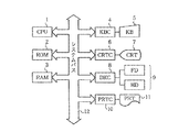
図1において、1はCPU、すなわち中央処理装置であり、この装置全体の制御および演算処理等を行うものである。2はROMすなわち読み出し専用メモリであり、システム起動プログラムおよび文字パターン・データ等の記憶領域である。3はRAMすなわちランダムアクセスメモリであり、使用制限のないデータ記憶領域であり、様々な処理毎に各々のプログラムおよびデータが記憶され、実行される領域である。4はKBCすなわちキーボード制御部であり、5のKBすなわちキーボードよりキー入力データを受け取りCPU1へ伝達する。6はCRTCすなわちディスプレイ制御部であり、7はCRTすなわちディスプレイ装置であり、6のCRTCよりデータを受け取り表示する。9はFDすなわちフロッピーディスク装置あるいはHDすなわちハードディスク装置等の外部記憶装置であり、プログラムおよびデータを記憶させておき、実行時必要に応じて参照またはRAMへロードする。8はDKCすなわちディスク制御部であり、データ伝送等の制御を行うものであり、10はPRTCすなわちプリンタ制御部であり、11はPRTすなわちプリンタ装置である。12はシステムバスであり、上述の構成要素間のデータの通路となるべきものである。
【0034】
また、図2も本発明にかかる本システムの基本的な構成を示すブロック図である。本システムはホストコンピュータ(図示せず)より印刷データ(イメージデータ、文字コード、コマンド等)を受け取り印刷を行うレーザビームプリンタであってもよいし、インクジェットプリンタあるいは熱転写等の出力機であってもよい。図2において21はCPU、すなわち中央処理装置であり、この装置全体の制御および演算処理等を行うものである。22はROMすなわち読み出し専用メモリであり、システム起動プログラムおよび文字パターン・データ等の記憶領域である。23はRAMすなわちランダムアクセスメモリであり、使用制限のないデータ記憶領域であり、様々な処理毎に各々のプログラムおよびデータが記憶され、実行される領域である。10はPRTCすなわち出力制御部であり、11はPRTすなわち印刷装置であり、10のPRTCよりデータを受け取り印刷する。
【0035】
〔第1実施例〕
次に、本発明の一実施例の詳細を図3のフローチャートを用いて説明する。図3は、字を構成するストロークごとにそのストロークを構成する輪郭の座標データで文字データが表現されている場合における、全体の流れを示すフローチャートである。このストロークで構成された輪郭は、それぞれ交差する輪郭である。ここで説明する例は、ウエイト(肉厚量)の異なる同一の書体がシステムに1つ存在するとき、そのデータを用いて異なるウエイトのデータを発生させるときの例である。
【0036】
ステップ3−1において図1のシステムにより実行されるアプリケーションプログラム、あるいは、図2のシステムにデータを供給するホストコンピュータ(図示せず)より入力パラメータを受け取る。ここで入力パラメータとしては出力すべき文字の文字コード、書体、ウエイト、出力サイズ、出力形式等がある。文字コードとしてはJISコード、シフトJISコード、EUCコード、UNIコード等のあらかじめ対象となるシステムがどの文字コード体系によって定められているかによって決まる。また書体としては明朝体、ゴシック体、丸ゴシック体等のシステムがあらかじめ内蔵しているデータあるいはオプションとして加えられたデータの中から選ばれる。ウエイトは前記書体の線の太さ情報であり、ここでは極細、細、中、太、極太等の情報が与えられる。出力サイズは実際にフォントデータを出力する際にどれ位の大きさで出力するかの情報である。出力形式は所望とするフォントの出力データ形式であり、輪郭の座標データ出力、ビットマップ出力等の要求が出される。
【0037】
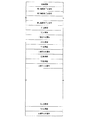
次にステップ3−2において対象文字の座標データを読み込む。このデータはROM、RAM、ハードディスク、フロッピーディスク等にあらかじめ格納されており、ステップ3−1で取り込んだ入力情報の書体情報や文字コード情報から検索して必要分読み込む。このとき取り込む入力情報は、図4に示すように、文字の輪郭の特徴点を抽出した座標情報であり、それぞれの点に対して直線データ/曲線データ判別フラグ、輪郭開始点/終了点フラグ等の属性情報を持つ。そしてここで扱う曲線データの補間式は2次あるいは2次Bスプライン曲線であったり、2次あるいは3次ベジェ曲線であったりするが、どの補間式を使用しているかはあらかじめ決定されている。また、文字枠を示す座標の最小値は0、最大値は800等で表現されている。また、各ストロークの枠の基準点への文字の原点からのオフセット情報を持つ。この座標データは、図5に示すようなフォーマットでROM等に格納されている。
【0038】
そして、ステップ3−3においては取り込んだ座標データを入力パラメータのウエイト情報に応じて太め/細め処理を行う。この時の処理は図10のフローチャートを用いて後で詳述するが、この太め/細め処理を行った結果、各々の輪郭線が太め/細め座標に変換される。図6には、図4に示す字形を太めの座標に変換した文字が示されている。このとき、太め/細め処理前と太め/細め処理後の座標点は1対1に対応しており、それぞれの点の持つ属性フラグは変化しない。そしてステップ3−4において、ステップ3−3で得られた太めた/細めた座標データを入力パラメータの出力サイズに応じて拡大縮小処理を行う。この時の計算方法は、要求出力サイズを(Ax,Ay)、ステップ3−3で得られたそれぞれの座標値を(x,y)、拡大縮小処理後のそれぞれの座標値を(X,Y)、格納されている文字枠のサイズを(Mx,My)とすると、
【0039】
【数1】
(X,Y)=(x×Ax/MX,y×Ay/My)
となる。上記計算を1文字が持つすべての座標列において計算する。また、このときステップ3−3で得られた各座標点における属性フラグは変化しない。
【0040】
ステップ3−5においては、入力パラメータの出力形式で判定し、出力形式が輪郭の座標データ出力であれば、ステップ3−6に進み、ステップ3−4で得られた拡大縮小後の座標点および座標点属性のデータ列を要求側へ返す。出力される輪郭の座標データのフォーマットは図5と同様である。
【0041】
ステップ3−5において、ビットマップ出力が要求されていれば、ステップ3−7へ進む。ステップ3−7からステップ3−13においては、実際に座標データからビットマップのデータを作成する処理である。ステップ3−7においては、対象となる座標データが直線であるかあるいは曲線であるかを判定する。対象となる座標データが直線である場合は、その座標点を直線のスタート点とし、次の座標点を直線のエンド点としてステップ3−8へ進む。対象となるデータが曲線データである場合はその座標点から曲線終了フラグが付されている座標データまでを曲線データとしてステップ3−9へ進む。
【0042】
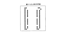
ステップ3−8においては、曲線を発生させる処理を行う。このときの直線発生方法はDDA(Digital Differential Algorithm)によって発生させる。そしてDDAによって発生させた座標データは図7に示すように打点テーブルに格納する。図7に示す打点テーブルは出力領域の各y座標に対して、x座標のスタート座標/ストップ座標を格納していく。DDAによって同一のy座標に対して複数のx座標が存在する場合は、ストロークの輪郭に対して最も外側になるようにx座標を設定する。なお、図7の打点テーブルは、曲線データによる塗りつぶしデータも入力されている。
【0043】
ステップ3−9においては、曲線データを短い直線(ショートベクトル)の集合に変換する処理を行う。図8に3次ベジェ曲線をショートベクトルの集合に変換する様子を示している。点A,B,C,Dはステップ3−3より得られた座標変換後の曲線データ(3次ベジェ曲線構成点)であり、これらの点からまず各点を結んだ直線の中点である点a,点b,点cを求める。点aは点Aと点Bの中点、点bは点Bと点Cの中点、点cは点Cと点Dの中点である。そして次に点x,点y,点zを求める。また、点a〜cを結んだ中点を求める。点xは点aと点bの中点、点zは点bと点cの中点、点yは点xと点zの中点である。そうすると点列Aaxyが新しい1つの3次ベジェ構成点、そして点列yzcDがもう1つの3次ベジェ構成点となる。そしてそれぞれのベジェ構成点を同様な操作で細分化してき、ある判定基準を満たしたらそのとき細分化を中止する。そしてそれまでにできた3次ベジェの構成点列がショートベクトルの集合となる。
【0044】
そしてステップ3−10において、ステップ3−9で求めたショートベクトルの集合に基づいて、打点テーブルに格納する。このテーブルに対する格納方法は、ステップ3−8で示した方法とまったく同様であり、すべてのショートベクトルに対して処理を終了するまで繰り返す。そしてステップ3−11において1つの輪郭の座標データがすべて終了したかどうかを判定し、処理が終了していればステップ3−13へ進み、処理が終了していなければステップ3−12に進む。ステップ3−12においては次のデータを処理するために現在の座標データへのポインタを更新する。直線の場合であれば次の座標データへポインタを更新し、曲線データであれば曲線の終了座標点までポインタを更新する。そしてステップ3−7に戻って新たに直線/曲線判定をして打点を行っていく。ステップ3−13においては1文字分すべての座標データに対して処理を終了したかどうかを判定し、すべての輪郭に対して処理を終了していればステップ3−15に進み、処理を終了していなければステップ3−14に進む。そしてステップ3−14においては、1輪郭が終了した後なので次の輪郭の先頭にポインタを進めステップ3−7に戻る。そして、最終的に、図7に示す打点テーブルが完成する。
【0045】
ステップ3−15においてはすべての座標データに対して打点処理が終了しているので、図9に示すように、ステップ3−8およびステップ3−10で打点テーブルに格納された各y座標に対するx座標に対してノンゼロワイディング方式で塗りつぶしを行う。この方式は各スキャンラインの左側からスキャンしていき、スタート点であればフラグの値をインクリメントし、エンド点であればデクリメントする。そしてフラグの値が0でなければその間は1として塗りつぶし処理を行う。そしてステップ3−16において要求側の指定する領域にステップ3−15で求められた1文字分のデータを返して処理を終了する。なお、要求側がPRTC10であればPRTC10にデータを返し、PRT11により印刷を行う。また、要求側がCRTC6であればCRTC6にデータを返し、CRT7により表示を行う。
【0046】
次に、図10のフローチャートを用いて、図3のステップ3−3における太め/細め処理の実施例を詳述する。本発明における太め/細めの処理は、ストロークに対応して太める/細めることにより、パラメータを変化させ、それぞれの輪郭点座標を変更する。図10のステップ10−1ではウエイトに応じて輪郭の太さのパラメータを決定する。太さを決定するパラメータは輪郭に大してそれぞれx方向、y方向の独立に値を持ち、横線の太め量および縦線の太め量をそれぞれ独立に管理する。例えば、明朝体を太めようとした場合、明朝体の横線はさほど太くせずに済むのに縦線は大きく太める必要があるため、x方向およびy方向に対してそれぞれ異なる値を設定する必要があるからである。これは例えば、図11の中明朝と太明朝とを比較すると明白である。一方、図12に示すように丸ゴシック体の場合は、横方向および縦方向はほぼ同じ量だけ太らせる必要がある。従って、それぞれの書体に対しても太めるべき値を変化させる必要がある。そこで、図13に示すように、それぞれの書体とウエイトにおける横線と縦線に対して線の中心から輪郭までの標準値のデータをあらかじめテーブルでもたせ、入力された対象座標データの書体およびウエイトと出力したい座標データのウエイトから輪郭の太め量をそれぞれx方向およびy方向に対して決定する。このときこの太め量が正の値となる場合は太め処理が行われ、太め量が負の値となる場合には細め処理が行われることになる。
【0047】
ステップ10−2においては、各ストロークのオフセット情報を太さパラメータに応じて変化させる。この値は、オフセットのx座標およびy座標から太さパラメータのx値およびy値を減じることによって求められる。
【0048】
ステップ10−3からステップ10−14までの間で1輪郭構成点のすべての座標点列に対して、太め/細め処理を行う。ステップ10−3では、まず処理を施すための対象点を取り込む。そしてステップ10−4で対象点の両隣の点を取り込む。ステップ10−5において、対象点とその両隣の点のなす角度を求める。この時の計算式は以下のようになる。対象点を点aとし、その両隣の点をそれぞれ点b,点cとすると、ベクトルabとベクトルacからその間の角度をθとすると、
【0049】
【数2】

となり、θを求めることができる。そしてステップ10−6に進み、θの角度によって移動すべき点の動きを変化させる。この角度が鋭くない角(たとえばθの値が30度以上)のときはステップ10−7に進み、また角度が鋭い角(たとえばθの値が30未満)のときはステップ10−8に進む。
【0051】
ステップ10−7ではθが鋭くない角のときの太め処理を行う。この処理を図14に示す図を用いて説明する。対象点をB、対象点の1つ前の点をA、対象点の次の点をCとすると、ベクトルAB、およびベクトルBCをなす角を2分する方向に対して、輪郭の外側に向けて移動する。その移動量は、ステップ10−1で求めたx太め量、y太め量によってその斜辺となるように決定する。このとき求められた座標値は1ストロークの枠に対する座標値であるので、ステップ10−2で求めたオフセット座標を加えて文字の原点からの座標値とする。
【0052】
ステップ10−8ないしステップ10−14におけるθが鋭い角ではある場合(θの値が30度未満)の太めの処理の説明を行う。ただし、太め量が正の値であるか負の値であるかによって処理を変える必要がある。そこでステップ10−8において、太め量が正の値であるか負の値であるかを判定する。太め量が正のときはステップ10−9へ進み、太め量が負の値である場合にはステップ10−13へ進む。
【0053】
ステップ10−9からステップ10−12で太め量が正の値のときの処理を行う。まずステップ10−9において、単純に鋭くない角のときと同様に、太め処理のための移動点B(図15参照)を求める。図15において、点a〜cは元の輪郭、点A〜Cは単純に太め処理をした輪郭の点である。しかし、鋭い角であるためこの移動点Bは元の点から大きく移動してしまい、ときには文字領域からはみだしてしまう場合がある。これを防ぐために、中間に新たな2点を設けて元の点から極端にはなれないよう処理を施す。
【0054】
ステップ10−10において、その新たな2点を計算によって求める処理を行う。この処理を図15を用いて説明する。図15において、元の輪郭の3点(点a,点b,点c)と単純に太め処理をした対応する輪郭の3点(点A,点B,点C)を用いて、ベクトルbBと同方向に距離が太め量の2倍の点Dを求める。ベクトルbDに垂直なベクトルでストロークをカットし、単純に太め処理を行った線分ABおよび線分BCと交わる点をそれぞれ点Eおよび点Fとすると、この2つの点Eおよび点Fを新たな太め処理した点として登録する。このようにして求められた座標点、点A,点E,点F,点Cが太め処理を施した新たな輪郭点として登録される。そしてステップ10−11において対象とする書体が丸ゴシック体のように角を丸める必要がある書体であるのかどうかを判定する。角を丸める必要がなければ、点A,点E,点F,点Cをそのまま太め処理後の構成点として登録しステップ10−15に進み、角を丸める必要がある書体であれば、ステップ10−12へ進み、角を丸める処理を行う。ステップ10−12においては、図16に示すように、線分EFの中間に新たな点Gをとりそして線分EGあるは線分GFと同じ長さの点をそれぞれ線分EA上に点Hを、線分FC上に点Iをとる。そして線分HE、線分EG、線分GFおよび線分FIの中点それぞれ点J,点K,点Lおよび点Mとすると、点列H,J,K,Gおよび点列G,L,M,Iをそれぞれベジェの構成点として表現することが可能となり、直線点列A,H、ベジェ曲線構成点列H,J,K,G、ベジェ曲線構成点列G,L,M,I、直線点列I,Cが角を丸めた新たな太め処理を施した輪郭構成点として登録される。以上ステップ10−9からステップ10−12において鋭い角度のとき、かつ太め量が正の場合の処理について説明した。
【0055】
次にステップ10−13からステップ10−14における、太め量が負の場合の処理について図17を用いて説明する。図17の各点の符号の意味は図15と同様である。ステップ10−13において、単純に鋭くない角のときと同様に太め処理のための移動点Bを求める。しかし、鋭い角であるためこの移動点は元の点から大きく移動してしまい、時にはストロークの線分をなくしてしまう場合がある。よってこれを防ぐために、点列a,b,cから求められた単純な太め用移動点列A,B,Cの点Bを点bに近づけるように配置し、ストロークの特徴を残す必要がある。そこでステップ10−14その近づけるための計算を行う。この計算方法は、ベクトルbBと同方向に距離が太め量の2倍の点Dを求め、この点を新たな太め処理の構成点とする。つまり点列A,D,Cが鋭い角度のとき、かつ太め量が負の場合のときの新たな輪郭構成点として登録される。以上のようにしてステップ10−8からステップ10−14において、太め処理の対象となる点が鋭い角をなしているときに太め量が正の場合、負の場合のそれぞれについて説明した。
【0056】
ステップ10−3からステップ10−14の処理を全輪郭点に対して処理することになる。10−15において1輪郭分のすべての座標点において処理を行っていればステップ10−17に進み、まだ処理すべき輪郭点が存在する場合には、ステップ10−16に進み、次の輪郭点へポインタを進めて再度太め処理を行う。
【0057】
ステップ10−17においては、1文字分のすべての輪郭において処理を行ったかどうかを判定し、すべて処理を行っていればステップ10−18へ進み、まだ処理すべき輪郭が存在するときは、次の輪郭にポインタを進めて再度太め処理を行う。そしてすべての輪郭座標点において太め処理が施されたときに、ステップ10−18に進む。
【0058】
太め/細め処理を行ったことにより、図18に示すように、文字の全体の枠が太め処理の場合大きくなり、細め処理の場合は小さくなってしまう。よって元の文字の全体枠に大きさを調整する必要がある。ステップ10−18においてその処理を行う。その調整のための拡大/縮小量は、ステップ10−1で求めた輪郭の太め量(細めの場合は負の値)の2倍分だけ太まっている。そこで、元の文字枠のX幅をBx、輪郭の太め量の横の値をFxとし、Y幅をBy、輪郭の太め量の縦の値をFyとし、太め処理を行った座標を(x,y)、調整後の座標を(X,Y)とすると、
【0059】
【数3】
(X,Y)=((x+Fx)×Bx/(Bx+Fx×2),(y+Fy)×By/(By+Fy×2))
で計算することができる。そしてこの計算を1文字分すべての座標点列において処理することによって図10に示した太め処理を終了する。
【0060】
〔第2実施例〕
次に他の実施例について説明する。ここで説明するのはあるウエイトの書体を要求したとき、同一の書体がシステムに2つ以上存在したときの例である。このときは要求するウエイトを複数ある同一の書体の中からどのウエイトの書体を基にして処理するかが重要である。従って基準となるウエイトの書体が決定すれば、その後のウエイト変換処理は前記実施例で示したものと同様の処理ができるので、ここでは、基準となるウエイトの選択方法のみついて説明し、それ以外は省略する。
【0061】
図19は、その詳細な処理の流れを示すフローチャートである。
【0062】
まず、記憶装置にどの書体のどのウエイトが格納されているかを検索する必要がある。そこで、図19におけるステップ19−1において、各書体のヘッダ部に記憶されているヘッダ情報を参照してテーブルにデータ存在情報を格納する。図20にそのテーブル及びデータ存在情報を示す。図20では、記憶装置に、明朝体のウエイト3とウエイト7、丸ゴシック体のウエイト5、角ゴシック体のウエイト6、楷書体のウエイト4とウエイト8が格納されている例である。ステップ19−2では、要求されたウエイトの情報がすでにROMあるいはハードディスク装置等の記憶装置に格納されているか否かを判定する。判定はステップ19−1で作成されたテーブルを検索していき、要求された書体とウエイトの情報により、データが記憶装置に格納されているか否かが分かる。要求されたウエイトの情報が記憶装置に格納されていれば、ステップ19−3へ進み、格納されていなければステップ19−4へ進む。
【0063】
ステップ19−3は要求されたウエイトの情報がすでに記憶装置に格納されていた場合であり、太め/細め処理を行う必要がないので記憶装置から座標データを読み込み、その座標データから出力サイズに応じて拡大縮小を行い、ビットマップフォントを作成して処理を終了する。
【0064】
ステップ19−4では、要求されたウエイトの情報が記憶装置にはない場合であり、太め/細め処理を行って要求されたウエイトの文字を出力する必要がある。そこで、その太め/細め処理を行う元となるデータを選択する必要がある。一般に細め処理を行う場合に比べて太め処理を行ったほうが品質的に劣化が少なくて済むので、要求されたウエイトよりも小さいウエイトの情報が記憶装置に格納されているか否かをステップ19−1で作成したテーブルを基に判定を行う。そして要求されたウエイトよりも小さいウエイトの情報が記憶装置に格納されていれば、ステップ19−5に進み、要求されたウエイトの情報が記憶装置に格納されていなければステップ19−6に進む。例えばウエイト5の明朝体を出力したい場合には、ウエイト3の明朝体が記憶装置に存在するのでステップ19−5に進み、ウエイト3の角ゴシック体を出力したい場合にはそれより小さいウエイトの角ゴシック体は存在しないのでステップ19−6に進む。ステップ19−5においては太め処理の元となるウエイトの書体の選択を行い、その太め処理のx方向、y方向のパラメータの設定を行う。ウエイト5の明朝体の出力要求の場合、ウエイト3の明朝体が存在するのでウエイト3とウエイト5の輪郭におけるx方向、y方向の差分を太めパラメータとしてセットする。ステップ19−6においては細め処理の元となるウエイトの書体の選択を行い、その細め処理の輪郭についてx方向、y方向のパラメータの設定を行う。ウエイト3の角ゴシック体の出力要求の場合、ウエイト6の角ゴシック体が存在するのでウエイト3とウエイト6の輪郭におけるx方向、y方向の差分を細めパラメータとしてセットする。
【0065】
以上のように、ステップ19−5およびステップ19−6で太めあるいは細めのパラメータのセットをした後は、前記第1の実施例で説明した通り処理を行い、所望のウエイトの文字を出力する。ここでは対象文字よりウエイトが小さい書体のデータが存在するか否かについて説明したが、対象文字よりもウエイトが大きい書体のデータが存在するか否かについて判定を行っても良い。また、対象文字のウエイトに最も近いウエイトのデータを選択して、そのデータを基にウエイト変換処理を行っても良い。
【0066】
〔第3実施例〕
次に他の実施例について説明する。ここで説明するのは前記第1、第2の実施例で説明した太め処理をグレイスケールフォントに対しても適用できることを説明する。ビットマップフォントの各ドットの値が0または1の2値のフォントであるのに対して、グレイスケールフォントは各ドットが0〜3あるいは0〜15あるいは0〜255等多値を扱うことが可能な多値フォントである。そしてこのグレイスケールフォントを生成するための方法として、一般には図21に示すようにn2 階調のグレイスケールフォントを出力するときは、図3のステップ3−4において出力サイズ要求の縦方向、横方向をそれぞれn倍して、その出力サイズによってビットマップフォントを作成する。そして図21に示すように縦横nビットで分割していきそれぞれのn×nの分割矩形領域の中に何ビット1が含まれているかによってグレイスケールの1ドットに対する多値の値が決定される。第1の実施例をグレイスケールフォントに応用した場合、図22に示すフローチャートのようになる。このフローチャートは、前記第1の実施例で説明したビットマップフォント発生あるいは輪郭座標出力のフローとほとんど同様であり、それぞれのステップは図3のステップとほぼ一致しているので、ここではグレイスケールフォント発生させることによって処理が異なるステップのところのみを説明する。異なるステップはステップ22−1、ステップ22−4であり、ステップ22−16およびステップ22−17は追加である。ステップ22−1においては、入力パラメータの取り込みであり、入力パラメータにグレイスケール情報が追加される。パラメータは、文字コード、書体、ウエイト情報、文字の出力サイズ、グレイのレベル、出力形式、出力器の特性等である。文字コードとしてはJISコード、シフトJISコード、EUCコード、UNIコード等のあらかじめ対象となるシステムがどの文字コード体系によって定められているかによって決まる。また書体としては、明朝体、ゴシック体、丸ゴシック体等のシステムがあらかじめ内蔵しているデータあるいはオプションとして加えられたデータの中から選ばれる。そしてこの時のデータの内容は、グレイスケールフォント発生のための特別なデータは格納されておらず、ビットマップフォント発生のときのデータとまったく同様である。ウエイト情報は、前記書体の線の太さ情報であり、ここでは極細、細、中、太、極太等の情報が与えられる。文字の出力サイズとしては、実際にフォントデータを出力する際にどれくらいの大きさで出力するかの情報であり、x方向、y方向のサイズが要求される。グレイのレベルは、グレイスケールフォントを発生させる際に何階調でグレイスケールフォントを作成するのかの情報である。これは4階調、16階調、256階調等出力器の特性に応じて設定される。出力形式は、所望するフォントの出力データ形式であり、座標データ出力、ビットマップフォント出力、グレイスケールフォント出力、1ドットの表現形式等がある。1ドットの表現形式は例えばグレイスケールフォントの場合は、1ドットを1バイトで表現するのか、あるいは2ドットや4ドットを1バイトで表現するのかといった表現形式の指定である。出力器の特性は、グレイスケールフォントを作成する際にどのようにしてグレイ値を決定すると対象とする出力器に対しても最も最適なグレイスケールフォントが得られるかといった情報である。ステップ22−4においては、出力サイズとグレイスケールフォントのグレイレベルによって、ステップ22−2で読み込んだ座標データに対して拡大縮小処理を行う。このとき拡大縮小するための計算式は、要求出力サイズを(Ax,Ay)、グレイレベルをn、ステップ22−3で得られたそれぞれの座標値を(x,y)、拡大縮小処理後のそれぞれの座標値を(X,Y)、格納されているデータの文字枠のサイズを(Mx,My)とすると、
【0067】
【数4】
(X,Y)=(x×√n×Ax/Mx,y×√n×Ay/My)
となる。
【0068】
ステップ22−16、およびステップ22−17においては、ステップ22−15で作成されたビットマップフォントからグレイスケールフォントを作成する処理を行う。まずステップ22−16においては、入力パラメータとして得られた出力器の特性によって、グレイスケール変換テーブルの選択を行う。グレイスケールフォント変換テーブルは、図23に示すように、16階調の場合4×4のマスクであらかじめ出力器の特性を表現するための値を格納しておく。図23の(a)の例では出力器の輝度特性がすべて均一になっている場合の例である。図23(b)の場合は、輝度がドットの中心部が高く周辺部が低い場合の例である。また図23(c)の場合は、輝度がドットの周辺部が高く中心部が低い場合の例である。これらの中から最も出力器の輝度特性に適したテーブルを選択する。そしてステップ22−17において、ステップ22−16で選択されたテーブルを元にグレイスケールフォントを作成する。この様子を図24を例にとって説明する。図24は、ステップ22−15で求められたビットマップフォントであり、その縦横のサイズはそれぞれグレイレベルnに対して、√n倍で作成されている。従って、縦横をそれぞれ√nで分割して、√n×√nのます目を抽出し、そのます目の1つに注目し、そのます目のビットの値とステップ22−16で求められたテーブルのます目の値とをそれぞれ対応するます目どうしを掛算する。そしてその結果の合計を取ることによって、対象となるドットのグレイスケール値が求められる。図24の例では、16階調のグレイスケールフォントを出力する場合の例であり、4×4のます目に対して図23(b)のテーブルが選択された場合の例を示した。この操作をすべてのます目に対して行うことによって、図25に示すようなグレイスケールフォントが生成される。そしてステップ22−18で出力形式に応じてグレイスケールフォントを格納して要求側へデータを返す。このとき出力形式が1ドットに対して1バイトの要求であればそれぞれのます目の値を1バイトに詰めて格納する。また隣り合う2点を1バイトに詰める要求であれば、1ドットを4ビットに詰めてデータを格納し、要求側へ返して処理を終了する。
【0069】
〔第4実施例〕
第1実施例〜第3実施例は、字を構成するストロークごとにそのストロークを構成する座標データでベクトルデータが表現されている場合におけるウエイト(太さ)の変換であった。
【0070】
これから説明する実施例は、ベクトルデータが、字の輪郭の座標データで表現されている場合についてのウエイトの変換である。その字形を図26に示す。これで分かるように、この輪郭は交差していない。図26に示されている字形を図27に示されるように、例えば太くする処理について説明する。ここで用いる字の輪郭の座標データのROM等に格納されているフォーマットは、例えば図28に示されている。これらは、ストロークごとにそのストロークを構成する座標データでベクトルデータを構成している字形を示している図4〜図6と比較すると理解が容易である。図28において、格納されているデータは、文字の輪郭の特徴点を抽出した座標情報であり、それぞれの点に対して直線データ/曲線データ判別フラグ、輪郭開始点/終了点フラグ等の属性情報を持つ。そしてここで扱う曲線データの補間式は2次あるいは2次Bスプライン曲線であったり、2次あるいは3次ベジェ曲線であったりするが、どの補間式を使用しているかはあらかじめ決定されている。また、文字枠を示す座標の最小値は0、最大値は800等で表現されている。
【0071】
この様なデータにおいて、ウエイトの変換処理を説明したのが図29に示したフローチャートである。図29に示したフローチャートは、図3のフローチャートと同じ部分が多いので、相違する処理ステップのみ説明する。ステップ29−1からステップ29−7までは、図3におけるステップ3−1からステップ3−7までと、処理の対象とするデータは相違しているが、ステップ29−3の太め/細め処理を除いて、各ステップの処理は同様であるので説明を省略する。ステップ29−3の処理は後で図34のフローチャートを用いて詳細に説明する。
【0072】
ステップ29−8において、直線を発生させる処理を行うが、この処理は、図3のステップ3−8とは、直線の発生の仕方は同様のDDAで行っているが、このとき2つの平面に対して行うことが異なっている。その1つの平面は塗りつぶし用XOR平面であり、もう1つの平面は輪郭用OR平面である。輪郭用OR平面は、塗りつぶし用XOR平面で抜けたビットを補うために設けている。これを図30の塗りつぶし用XOR平面を示す図及び図31の輪郭用OR平面を示す図を用いて説明する。図30の塗りつぶし用XOR平面には、1つのY座標に対してX座標を1つのみ打点する。これは、後で説明する塗りつぶしの処理(ステップ29−16)において、各ラインで左側から右側にスキャンしていき、奇数個の目の1から偶数個目の1までの間を1で塗りつぶすため、1つのY座標に対して1つのX座標にしておかないと、うまく塗りつぶすことができないためである。そして、このときの塗りつぶし用XOR平面に打点する方法は、対象とする座標点における塗りつぶし用XOR平面の値と1との排他的論理和(XOR)の論理演算を行い、その結果を塗りつぶし用XOR平面上の対象とする座標点に格納することで行う。そして、もう一つの平面は図31に示した輪郭用OR平面であり、この平面に対して打点するときは、1つのY座標に対して直線にかかっている全てのX座標を1とする。この輪郭用OR平面で、塗りつぶし用XOR平面で抜けたビットを補うことができる。
【0073】
ステップ29−9及びステップ29−10で曲線の発生させる処理を行うが、直線と同様に2平面に対して打点処理を行うことを除いて図3のステップ3−9及びステップ3−10と同様であるので、説明を省略する。
【0074】
ステップ29−11から29−14までのステップも図3のステップ3−11から3−14までのステップと同様の処理なので説明を省略する。
【0075】
ステップ29−15で塗りつぶし用平面に対して塗りつぶし処理を行う。この処理を図32を用いて説明する。図32の矢印に示すように、塗りつぶし用平面で各スキャンライン単位で左側からスキャンしていき、奇数個目の1から偶数個目の1までの間を1で塗りつぶす処理を行う。この処理を全てのスキャンラインに対して行う。ステップ29−16で、ステップ29−15で求めた塗りつぶしXOR平面と輪郭用OR平面とのORをとって1文字のビットマップデータを完成させる。この様子を示したのが図33である。ステップ29−17において例えば要求側の指定する記憶領域にステップ29−16で求めた1文字分のビットマップデータを返して処理を終了する。
【0076】
次に図34のフローチャートを用いて、図29のステップ29−3における太め/細め処理を詳細述する。この処理は図10で説明した処理と重複する部分が多いので、異なる処理を行っている部分のみ説明する。
【0077】
まず、文字を構成する輪郭において、外側の輪郭と内側の輪郭のそれぞれの場合によって太める/細めるパラメータが異なっているため、輪郭の区別を判別する必要がある。そして、外輪郭に対しては外輪郭太め/細めパラメータ、内輪郭に対しては内輪郭太め/細めパラメータを適用して太め/細め処理を行う。この処理が図10の処理と異なっている。この処理は、ステップ34−1からステップ34−5で行っている。
【0078】
さて、輪郭を構成する外側の輪郭点列は左まわりで構成されているとする。そして内側の輪郭点は逆の右まわりで構成されているとする。この場合は輪郭点のまわり方を判定することにより、外側の輪郭であるか、内側の輪郭であるかを判定する。なお、この逆、即ち右まわりの場合を外輪郭、左まわりの場合を内輪郭としてもよい。
【0079】
ステップ34−1からステップ34−3でその判定をするための前処理を行っている。この処理を図35を参照しながら説明する。まず、ステップ34−1において、図35に示すスタート点Sを取り出し、次にステップ34−2において、図35のスタート点Sの両側の2点A,Bを抽出する。点Aはスタート点Sの一つ前の点(その輪郭の最後の点)、点Bはスタート点の一つ後の点である。図35において、ベクトルAS及びベクトルSBのなす角度を2分割する方向に前処理用の点を設ける。この点は、外輪郭であるとき即ち左まわりのときはベクトルの方向に向かって右側に、内輪郭であるとき即ち右まわりのときはベクトルの方向に向かって左側に、スタート点からある定められた値離れた点である。これがステップ34−3の処理である。そして、ステップ34−4において、この点を基に対象とする輪郭が外輪郭であるのか、内輪郭であるのか判定する。この処理を後で図40のフローチャートを用いて詳しく説明する。
【0080】
そして、ステップ34−5でウエイトに応じて外輪郭の太さ及び内輪郭の太さのパラメータを決定する。太さを決定するパラメータは、外輪郭及び内輪郭に対してx方向、y方向それぞれ独立に値を持ち、横線の太め量及び縦線の太め量をそれぞれ独立に管理する。これは、例えば図36に示すように、明朝体を太めようとした場合、明朝体の横線はさほど太くせずに済むのに縦線は大きく太める必要があるため、x方向,y方向に対し、それぞれ異なる値を設定する必要があるからである。また、図37に示すように丸ゴチック体の場合は、横方向及び縦方向はほぼ同じ量だけ太らせている。この考え方は、図10のステップ10−1及び図11,図12と同様である。図38に示すように、それぞれの書体とウエイトにおける横線と縦線に対して線の中心から外輪郭あるいは内輪郭までの標準値のデータを予めテーブルに持たせ、入力された対象座標データの書体及びウエイトの出力したい座標データのウエイトから外輪郭及び内輪郭の太め量をそれぞれx方向、y方向に対して決定する。
【0081】
ステップ34−6〜ステップ34−21の処理は、対象とする座標データは相違しているが、処理の流れは図10のおける処理と同様なので説明を省略する。ただし、これらの処理で、外輪郭、内輪郭を考慮していることが図10の処理と異なっている。これは、鋭くない角のときの太め処理を行うステップ34−10において、外輪郭即ち左まわりのときは右側に移動する(図39参照)。なお、外輪郭が右まわりとなっているときは左側に移動する。
【0082】
さて、図40のフローチャートを用いて、図34のステップ34−4における外輪郭/内輪郭判定処理について説明する。この処理を図41に示すように、輪郭を形成する座標点ABCDEに対して、ある点Zからの2点に対する角θ1 〜角θ4 を左まわりを正として角度を求めて、角θ1 〜角θ4 の合計の角度が2πになるとき、ある点Zは輪郭の内側にあると判定する。また、図42に示すように、同様に輪郭を形成する点A〜Dとある点Zとでなす角θ1 〜角θ4 の合計の角度が0である場合は、ある点Zは輪郭の外側にあると判定する。この処理を示したのが図40のフローチャートである。ある点Zは、図34のステップ34−1〜ステップ34−3で求めているので、図40のフローチャートはその点からの角度の総和を求める処理を行う。ステップ40−1において、まず、角度の総和を0として初期化を行う。ステップ40−2において隣り合った2点を抽出し、ステップ40−3である点Zと抽出した2点とをベクトルで結び、間の角度を求める。その角度は外積を計算することで求めることができる。その求めた値をステップ40−4で角度の総和に加える。ステップ40−5では1輪郭の全ての点を2点づつ抽出したか判定し、全ての点に対して計算を終了したときはステップ40−6に進み、終了していないときはステップ40−2の戻って再度計算を行う。ステップ40−6で、総和が0か2πかを判定し、0であれば外輪郭と判定し外輪郭フラグを立て、2πであれば内輪郭であると判定し内輪郭フラグを立てる。あとの処理では、このフラグで外輪郭であるか内輪郭であるかを判別する。
【0083】
〔第5実施例〕
第5実施例は、先に説明した第2実施例に対応するもので、交差しない輪郭により座標データが表現されている場合における同一の書体がシステムに2以上存在したときの例である。このときも図19のフローチャートと同様に、細め処理を行ったときに比較して太め処理を行ったときの方が品質の劣化が少ないので、要求されたウエイトより小さい輪郭の座標データを選択する。この処理は図19のフローチャートにおける処理と同様であるので説明を省略する。
【0084】
なお、このとき使用する図20に示したテーブルに対応するものを、図43に示す。
【0085】
〔第6実施例〕
第6実施例は、先に説明した第3実施例と対応するもので、交差しない輪郭により座標データが表現されている場合におけるグレースケールフォントに太め処理をした場合を説明するものである。この処理は図44のフローチャートに示されている。この図44のフローチャートは、図22に示されているフローチャートとは、図29のフローチャートと同様に2平面に対して処理をしていることが異っているだけで、同様の処理を行っている。従ってこの処理の説明を省略する。この図44の処理は、図3と図29との相違を理解して、図22を参照すると明白である。
【0086】
なお、本発明は複数の機器からなるシステムにおいて、達成されても良く、1つの機器からなる装置において達成されても良い。また、システムあるいは装置にプログラムを供給することにより、本発明が達成される場合にも適用されることは言うまでもない。
【0087】
【発明の効果】
以上説明したように、本発明によれば、入力された太字量または細字量に基づいて、輪郭データの座標値を変換し、調整すべき座標を抽出し、座標値を調整し、調整された輪郭データに基づいて太いまたは細い文字パターンを発生させるので、少ない文字データから肉厚量の異なる高品質な太字または細字文字を発生することができる。
【0088】
本発明によれば、入力された太字量または細字量に基づいて、変換するいずれかの文字データ候補を決定し、該決定された文字データに対応する輪郭データの座標値を変換し、該座標変換された輪郭データに基づいて、太いまたは細い文字パターンを発生しているので、文字データ資源を生かして最良の太字または細字の文字データを発生させることができる。
【0089】
本発明によれば、決定は、入力された太字量または細字量に近い肉厚量の文字データを変換する文字データ候補として、より厳密な太字または細字の文字データを発生させることができる。
【0090】
また、本発明によれば、変換は、対象座標に隣接する2点の座標値を参照して1つの変換座標を決定することにより行うので、バランスのとれた太いまたは細字の文字パターンを発生することができる。
【0091】
本発明によれば、変換は、抽出した各輪郭データを入力された太字量または細字量をx方向およびy方向に対して独立して可変するにより行うので、書体毎の特徴を生かした太字または細字の文字パターンを発生することができる。
【0092】
本発明によれば、判定は、対象座標と隣接する2点の座標値を参照して3点のなす角度および入力された値が太字量あるいは細字量であるかおよび対象書体によって決定することにより行うので、良好な品質の太字または細字の文字パターンを発生することができる。
【0093】
本発明によれば、座標調整は、太字量が指定されたときに対象点に新たな点を挿入することにより行うので、良好な品質の太字の文字パターンを発生することができる。
【0094】
本発明によれば、座標調整は、太字量が指定されたときに対象点に新たな点を挿入した後、角を丸めることによって行うので、書体毎の特徴を生かした良好な太字の文字パターンを発生することができる。
【0095】
本発明によれば、座標調整は、細字量が指定されたときに対象点を移動させることによって行うので、良好な品質の細字の文字パターンを発生することができる。
【0096】
本発明によれば、データの発生は、変換された輪郭データに基づいてビットマップフォント、輪郭データ、グレイスケールフォントのいずれかを出力して、種々の出力手段に適切なデータ形式で太字または細字の文字データを供給することができる。
【0097】
前記輪郭データは、交差するストロークによる複数の輪郭データで構成されていてもよいし、交差しない複数の文字の輪郭データで構成されていてもよい。
【0098】
従って、少ないメモリ容量で、様々な肉厚量の各書体の文字データを良好に発生できるという効果を奏する。
【図面の簡単な説明】
【図1】本発明の内部構成を示すブロック図である。
【図2】本発明の他の内部構成を示すブロック図である。
【図3】本発明のストロークによるアウトラインフォントに対する処理全体の流れを示すフローチャートである。
【図4】本発明に用いるストロークによるアウトラインフォントを説明する図である。
【図5】ストロークによる輪郭の座標データのフォーマットを示す図である。
【図6】本発明によって変換されたアウトラインフォントを示す図である。
【図7】座標データから塗りつぶしテーブルを作成する様子を示す図である。
【図8】3次ベジェ曲線を分解する様子を示す図である。
【図9】塗りつぶしテーブルからビットマップフォントを作成する様子を示す図である。
【図10】太め処理の詳細を示すフローチャートである。
【図11】明朝体の太め処理結果を示す図である。
【図12】丸ゴシック体の太め処理を示す図である。
【図13】太めパラメータを決定するために用いるテーブルを示す図である。
【図14】太め処理を行っている様子を示す図である。
【図15】太め量が正で鋭い角度のとき点を分割する様子を示す図である。
【図16】分割した点を丸接合する様子を示す図である。
【図17】太め量が負のときの鋭い角度の対応を示す図である。
【図18】太め処理によって不都合が生じる様子を示す図である。
【図19】本発明の他の実施例の全体の流れを示すフローチャートである。
【図20】太めパラメータを決定するために用いるテーブルを示す図である。
【図21】グレイスケールフォントにするために作成するビットマップを示す図である。
【図22】本発明の他の実施例の全体の流れを示すフローチャートである。
【図23】グレイスケールフォントに変換するための基本概念図である。
【図24】グレイスケースフォントに変換するための様子を示す図である。
【図25】グレイスケールフォントに変換された様子を示す図である。
【図26】本発明に用いる交差しない輪郭によるアウトラインフォントを説明する図である。
【図27】本発明によって変換された交差しない輪郭によるアウトラインフォントを示す図である。
【図28】交差しない輪郭による座標データのフォーマットを示す図である。
【図29】本発明の交差しない輪郭によるアウトラインフォントに対する処理全体の流れを示すフローチャートである。
【図30】座標データから塗りつぶし用XOR平面を示す図である。
【図31】座標データから輪郭用OR平面を示す図である。
【図32】塗りつぶし用平面で塗りつぶしを行う様子を示す図である。
【図33】ビットマップフォントを発生する様子を示す図である。
【図34】交差しない輪郭による輪郭データの太め処理の詳細を示すフローチャートである。
【図35】スタート点の仮移動を説明する図である。
【図36】明朝体の太め処理結果を示す図である。
【図37】丸ゴシック体の処理結果を示す図である。
【図38】太めパラメータを決定するために用いるテーブルを示す図である。
【図39】太め処理を行っている様子を示す図である。
【図40】内輪郭/外輪郭を判定する処理を示すフローチャートである。
【図41】内輪郭を判定を説明する図である。
【図42】外輪郭を判定を説明する図である。
【図43】太め又目ータを決定するためのテーブルを示す図である。
【図44】グレイスケールフォントを生成するためのフローチャートである。
【符号の説明】
1 CPU(中央処理装置)
2 ROM(読み出し専用メモリ)
3 RAM(ランダムアクセスメモリ)
4 KBC(キーボード制御部)
5 KB(キーボード)
6 CRTC(ディスプレイ制御部)
7 CRT(ディスプレイ装置)
8 DKC(ディスク制御部)
9 外部記憶装置
10 PRTC(プリンタ制御部)
11 PRT(プリンタ装置)
12 システムバス[0001]
[Industrial applications]
The present invention relates to a character generating apparatus and method for converting the thickness of a character coded by coordinate data of a contour.
[0002]
[Prior art]
Conventionally, when data stored as coordinate data of an outline is developed into a bit map and a character is output, the coordinate data of the outline stored in a ROM or a hard disk is read, and the coordinate data is multiplied by a scaling ratio to obtain a desired value. Character data was obtained by converting to dot format after converting to size.
[0003]
In this case, even if the same typeface has different weights (thickness and wall thickness), it is necessary to have one piece of coordinate data for each. However, in the case of a Japanese document type, there are about 8000 characters per typeface, and the capacity of outline data required for one typeface is about 1 Mbyte to 3 Mbytes. If the weight coordinate data is provided for each weight, the capacity becomes enormous.
[0004]
For this reason, when generating data of different weights in the same font from data of one font, it is calculated and calculated from three points, two points adjacent to the target coordinates of the coordinates, based on the amount of thickening or thinning. (See Japanese Patent Application Nos. 5-309555 and 5-309556 filed by the present applicant earlier).
[0005]
[Problems to be solved by the invention]
However, in the above case, if an attempt is made to convert a straight line that is sharply bent such that the angle formed by the three points is, for example, 30 degrees or less, the target point protrudes from the character area or significantly impairs the shape of the character. There was a problem.
[0006]
SUMMARY OF THE INVENTION The present invention has been made to solve the above-described problem, and generates data of different weights (thickness) in the same font with good quality from data of at least one font, with a small memory capacity, An object of the present invention is to make it possible to generate data of a font having various weights.
[0007]
[Means for Solving the Problems]
In order to achieve the above object, the present invention provides a character generating device that performs a thickening process on a character outline and generates a character based on the thickened outline, Discriminating means for discriminating whether or not the angle between the thickened target contour point and the contour points on both sides thereof is a sharp angle; and the discriminating means determines whether the thickened target contour point and the contour points on both sides thereof are thick. Correction means for correcting the thickened target contour point when it is determined that the angle to be formed is a sharp angle, wherein the correction means Me If the thickening amount of the processing is negative, the target contour point subjected to the thickening processing is referred to as the target contour point. The subject Contour point Contour points before processing Tie Bunch line Above, on the contour point side before processing It is characterized by moving to a new contour point.
[0008]
According to a second aspect of the present invention, there is provided the character generator according to the first aspect, wherein the line intersects at right angles with a straight line connecting the thickened target contour point and the contour point before the processing of the target contour point. Correcting the target contour point by finding the intersection of the straight line with the target contour point and two straight lines connecting the adjacent contour points as a new contour point, and replacing the target contour point with the new contour point. It is a feature.
[0009]
According to a third aspect of the present invention, in the second aspect of the present invention, when the corners need to be rounded, the correction means obtains a curve composing point based on the obtained new contour point. It is characterized by the following.
[0010]
According to a fourth aspect of the present invention, there is provided the character generating device according to the first aspect, wherein the coordinate value of the outline point thickened by the thickening processing is set to the width of the character frame of the original character and the thickness of the character frame. Amount And adjusting means for adjusting based on the above.
[0011]
The invention according to
[0012]
According to a sixth aspect of the present invention, there is provided the character generating method according to the fifth aspect, wherein when the thickening amount of the thickening process is positive, the thickened target contour point and the target contour point before the processing are processed. The intersection point of a straight line that intersects at right angles with the straight line connecting the contour points of the target contour point and two straight lines connecting the contour points on both sides thereof is obtained as a new contour point, and the target contour point is calculated as the new contour point. It is characterized in that the target contour point is corrected by replacement.
[0013]
According to a seventh aspect of the present invention, in the character generation method according to the sixth aspect, when the corners need to be rounded, the correction step includes the step of forming a curve forming point based on the obtained new contour point. Is obtained.
[0014]
The invention according to
[0020]
[Action]
The present invention converts the coordinate value of the outline data based on the input bold character amount or the thin character amount, extracts coordinates to be adjusted, adjusts the coordinate value, and adjusts the coordinate value based on the adjusted outline data. Since a character pattern is generated, high-quality bold or fine characters with different thicknesses are generated from a small amount of character data.
[0021]
In the present invention, one of character data candidates to be converted is determined based on the input bold character amount or thin character amount, and the coordinate value of the outline data corresponding to the determined character data is converted. A thick or thin character pattern is generated based on the obtained outline data, and the best bold or thin character data is generated by utilizing the character data resources.
[0022]
In the present invention, the determination is to generate more strict bold or thin character data as character data candidates for converting the input bold or thin character data.
[0023]
Further, in the present invention, since the conversion is performed by determining one conversion coordinate with reference to the coordinate values of two points adjacent to the target coordinate, a well-balanced thick or thin character pattern is generated. It is.
[0024]
In the present invention, since the conversion is performed by independently varying the amount of the extracted bold or thin characters in the x-direction and the y-direction for each of the extracted outline data, the bold or thin character utilizing the characteristics of each typeface is used. Is generated.
[0025]
In the present invention, the determination is made by referring to the coordinate values of two points adjacent to the target coordinate and determining the angle formed by the three points, whether the input value is the bold or fine character amount, and the target font. Therefore, a good quality bold or thin character pattern is generated.
[0026]
In the present invention, since the coordinate adjustment is performed by inserting a new point at the target point when the bold character amount is designated, a bold character pattern of good quality is generated.
[0027]
In the present invention, the coordinate adjustment is performed by inserting a new point at the target point when the amount of bold characters is specified, and then by rounding the corners, so that a good bold character pattern utilizing the characteristics of each typeface can be obtained. What happens.
[0028]
In the present invention, since the coordinate adjustment is performed by moving the target point when the fine character amount is specified, a fine quality character pattern of good quality is generated.
[0029]
In the present invention, the data is generated by outputting any one of a bitmap font, contour data, and a grayscale font based on the converted contour data, and converting the data to a bold or thin font in a data format suitable for various output means. It supplies character data.
[0030]
The outline data may be constituted by a plurality of outline data of intersecting strokes, or may be constituted by outline data of a plurality of non-intersecting characters.
[0031]
【Example】
Next, an embodiment of the present invention will be described with reference to the drawings.
[0032]
FIG. 1 is a block diagram showing a basic configuration of a system used in the present invention. The system used in the present invention may be a Japanese word processor, a workstation or a computer system.
[0033]
In FIG. 1,
[0034]
FIG. 2 is also a block diagram showing a basic configuration of the present system according to the present invention. This system may be a laser beam printer that receives print data (image data, character codes, commands, etc.) from a host computer (not shown) and performs printing, or may be an output device such as an ink jet printer or thermal transfer. Good. In FIG. 2,
[0035]
[First embodiment]
Next, details of one embodiment of the present invention will be described with reference to the flowchart of FIG. FIG. 3 is a flowchart showing an overall flow in a case where character data is represented by coordinate data of a contour constituting a stroke for each stroke constituting a character. The contours formed by the strokes are crossing contours. The example described here is an example in which, when the same typeface having different weights (thickness amounts) exists in the system, data of different weights is generated using the data.
[0036]
In step 3-1, input parameters are received from an application program executed by the system of FIG. 1 or a host computer (not shown) for supplying data to the system of FIG. Here, the input parameters include a character code of a character to be output, a font, a weight, an output size, an output format, and the like. The character code is determined depending on which character code system defines a target system such as a JIS code, a shift JIS code, an EUC code, or a UNI code in advance. In addition, the typeface is selected from data pre-installed in the system such as Mincho, Gothic, and Round Gothic, or data added as an option. The weight is information on the line thickness of the typeface, and here, information such as extra fine, fine, medium, thick, and extra thick is given. The output size is information on how large the font data should be when actually outputting the font data. The output format is an output data format of a desired font, and a request for outputting coordinate data of a contour, outputting a bitmap, or the like is issued.
[0037]
Next, in step 3-2, the coordinate data of the target character is read. This data is stored in advance in a ROM, a RAM, a hard disk, a floppy disk, or the like. The data is retrieved from the typeface information and character code information of the input information captured in step 3-1 and read as needed. As shown in FIG. 4, the input information to be taken in at this time is coordinate information obtained by extracting characteristic points of the outline of the character, and for each point, a straight line data / curve data discrimination flag, a contour start point / end point flag, and the like. With attribute information. The interpolation formula of the curve data handled here is a quadratic or quadratic B-spline curve, or a quadratic or cubic Bezier curve, and it is determined in advance which interpolation formula is used. The minimum value of the coordinates indicating the character frame is represented by 0, and the maximum value is represented by 800 or the like. Also, it has offset information from the origin of the character to the reference point of the frame of each stroke. This coordinate data is stored in a ROM or the like in a format as shown in FIG.
[0038]
In step 3-3, the acquired coordinate data is subjected to a thickening / thinning process according to the weight information of the input parameter. The processing at this time will be described later in detail with reference to the flowchart of FIG. 10. As a result of performing the thickening / thinning processing, each outline is converted into thick / thin coordinates. FIG. 6 shows characters obtained by converting the character shape shown in FIG. 4 into thicker coordinates. At this time, the coordinate points before the thickening / thinning processing and the coordinate points after the thickening / thinning processing have a one-to-one correspondence, and the attribute flags of each point do not change. In step 3-4, the thick / thin coordinate data obtained in step 3-3 is enlarged or reduced according to the output size of the input parameter. The calculation method at this time is such that the requested output size is (Ax, Ay), the respective coordinate values obtained in step 3-3 are (x, y), and the respective coordinate values after the enlargement / reduction processing are (X, Y). ), And the size of the stored character frame is (Mx, My),
[0039]
(Equation 1)
(X, Y) = (xxAx / MX, yxAy / My)
It becomes. The above calculation is performed for all coordinate strings of one character. At this time, the attribute flag at each coordinate point obtained in step 3-3 does not change.
[0040]
In step 3-5, determination is made based on the output format of the input parameters. If the output format is coordinate data output of the contour, the process proceeds to step 3-6, where the coordinate points after enlargement / reduction obtained in step 3-4 and Returns the coordinate point attribute data string to the requesting side. The format of the coordinate data of the output contour is the same as in FIG.
[0041]
If it is determined in step 3-5 that bitmap output is requested, the process proceeds to step 3-7. Steps 3-7 to 3-13 are processes for actually creating bitmap data from the coordinate data. In step 3-7, it is determined whether the target coordinate data is a straight line or a curve. If the target coordinate data is a straight line, the process proceeds to step 3-8 with that coordinate point as the start point of the straight line and the next coordinate point as the end point of the straight line. If the target data is curve data, the process proceeds from step 3-9 to the coordinate data from the coordinate point to the coordinate data with the curve end flag.
[0042]
In step 3-8, processing for generating a curve is performed. The straight line generation method at this time is generated by a DDA (Digital Differential Algorithm). The coordinate data generated by the DDA is stored in a dot table as shown in FIG. The dot table shown in FIG. 7 stores start coordinates / stop coordinates of x coordinates for each y coordinate of the output area. If a plurality of x-coordinates exist for the same y-coordinate by DDA, the x-coordinate is set so as to be the outermost with respect to the outline of the stroke. Note that, in the hit point table of FIG. 7, fill data based on curve data is also input.
[0043]
In step 3-9, a process of converting the curve data into a set of short straight lines (short vectors) is performed. FIG. 8 shows how a cubic Bezier curve is converted into a set of short vectors. Points A, B, C, and D are the curve data (cubic Bezier curve constituent points) after the coordinate conversion obtained in step 3-3, and are the middle points of a straight line connecting these points first from these points. Points a, b, and c are obtained. Point a is the midpoint between points A and B, point b is the midpoint between points B and C, and point c is the midpoint between points C and D. Then, points x, y, and z are obtained. Also, a midpoint connecting points a to c is obtained. Point x is the midpoint between points a and b, point z is the midpoint between points b and c, and point y is the midpoint between points x and z. Then, the point sequence Aaxy becomes one new cubic Bezier constituent point, and the point sequence yzcD becomes another cubic Bezier constituent point. Then, each Bezier constituent point is subdivided by the same operation, and when a certain criterion is satisfied, the subdivision is stopped at that time. The cubic Bezier constituent point sequence thus far is a set of short vectors.
[0044]
Then, in step 3-10, the short vectors are stored in the hitting point table based on the set of short vectors obtained in step 3-9. The storage method for this table is exactly the same as the method shown in step 3-8, and is repeated until the processing is completed for all short vectors. Then, in step 3-11, it is determined whether or not all the coordinate data of one outline has been completed. If the processing has been completed, the process proceeds to step 3-13, and if not, the process proceeds to step 3-12. In step 3-12, the pointer to the current coordinate data is updated to process the next data. If it is a straight line, the pointer is updated to the next coordinate data, and if it is curve data, the pointer is updated to the end coordinate point of the curve. Then, the process returns to step 3-7, where a new straight / curve determination is performed to perform the hitting. In step 3-13, it is determined whether or not processing has been completed for all coordinate data for one character. If processing has been completed for all contours, the flow advances to step 3-15 to terminate the processing. If not, proceed to step 3-14. Then, in step 3-14, since one contour has been completed, the pointer is advanced to the head of the next contour and the process returns to step 3-7. Finally, the dot table shown in FIG. 7 is completed.
[0045]
In step 3-15, since the dot processing has been completed for all coordinate data, as shown in FIG. 9, x for each y coordinate stored in the dot table in steps 3-8 and 3-10. The coordinates are painted using the non-zero width method. In this method, scanning is performed from the left side of each scan line, and the flag value is incremented at a start point and decremented at an end point. If the value of the flag is not 0, it is set to 1 during that time, and the painting process is performed. Then, in step 3-16, the data for one character obtained in step 3-15 is returned to the area designated by the requesting side, and the process is terminated. If the requesting side is PRTC10, data is returned to PRTC10, and printing is performed by PRT11. If the requesting side is CRTC6, data is returned to CRTC6, and display is performed by CRT7.
[0046]
Next, an example of the thickening / thinning process in step 3-3 in FIG. 3 will be described in detail with reference to the flowchart in FIG. In the thickening / thinning process according to the present invention, the parameters are changed and the coordinates of each contour point are changed by thickening / thinning corresponding to the stroke. In step 10-1 in FIG. 10, the parameter of the thickness of the contour is determined according to the weight. The parameters for determining the thickness have independent values in the x and y directions, respectively, for the contour, and the thickening amount of the horizontal line and the thickening amount of the vertical line are independently managed. For example, when trying to make the Mincho font thicker, it is necessary to make the vertical line much thicker without having to make the horizontal line much thicker, so set different values for the x and y directions respectively. It is necessary to do it. This is evident, for example, when comparing the Minming and Taiming ages in FIG. On the other hand, in the case of a round Gothic body as shown in FIG. 12, it is necessary to make the horizontal and vertical directions fat by the same amount. Therefore, it is necessary to change the value to be thickened for each typeface. Therefore, as shown in FIG. 13, data of standard values from the center to the outline of the horizontal line and vertical line in each typeface and weight are stored in a table in advance, and the typeface and weight of the input target coordinate data are stored in the table. The thickening amount of the contour is determined for the x direction and the y direction from the weight of the coordinate data to be output. At this time, when the thickening amount has a positive value, the thickening process is performed, and when the thickening amount has a negative value, the thinning process is performed.
[0047]
In step 10-2, the offset information of each stroke is changed according to the thickness parameter. This value is obtained by subtracting the x and y values of the thickness parameter from the x and y coordinates of the offset.
[0048]
From step 10-3 to step 10-14, the thickening / thinning process is performed on all the coordinate point sequences of one contour composing point. In step 10-3, first, a target point to be processed is fetched. Then, in step 10-4, points on both sides of the target point are fetched. In step 10-5, the angle between the target point and its neighboring points is determined. The calculation formula at this time is as follows. Assuming that the target point is a point a and its neighboring points are a point b and a point c, respectively, if an angle between the vector ab and the vector ac is θ,
[0049]
(Equation 2)
And θ can be obtained. Then, the process proceeds to step 10-6, in which the movement of the point to be moved is changed according to the angle θ. If the angle is not sharp (eg, the value of θ is 30 degrees or more), the process proceeds to step 10-7. If the angle is sharp (eg, the value of θ is less than 30), the process proceeds to step 10-8.
[0051]
In step 10-7, thickening processing is performed when θ is not a sharp corner. This processing will be described with reference to the diagram shown in FIG. Assuming that the target point is B, the point immediately before the target point is A, and the point next to the target point is C, the direction of dividing the angle between the vector AB and the vector BC into two is directed outward of the contour. Move. The amount of movement is determined by the x-thickness and y-thickness determined in step 10-1 so as to be on the hypotenuse. Since the coordinate value obtained at this time is a coordinate value for a one-stroke frame, the offset coordinate obtained in step 10-2 is added to obtain a coordinate value from the origin of the character.
[0052]
The thick processing in step 10-8 to step 10-14 when θ is a sharp angle (the value of θ is less than 30 degrees) will be described. However, the processing needs to be changed depending on whether the thickening amount is a positive value or a negative value. Therefore, in step 10-8, it is determined whether the thickening amount is a positive value or a negative value. When the thickening amount is positive, the process proceeds to Step 10-9, and when the thickening amount is a negative value, the process proceeds to Step 10-13.
[0053]
In steps 10-9 to 10-12, processing is performed when the thickening amount is a positive value. First, in step 10-9, the moving point B (see FIG. 15) for the thickening process is obtained in the same manner as when the corner is simply not sharp. In FIG. 15, points a to c are points of the original contour, and points A to C are points of the contour which has been simply thickened. However, because of the sharp corner, the moving point B moves greatly from the original point, and sometimes moves out of the character area. In order to prevent this, two new points are provided in the middle, and processing is performed so as not to be extreme from the original point.
[0054]
In step 10-10, a process for calculating the new two points is performed. This processing will be described with reference to FIG. In FIG. 15, a vector bB and a vector bB are obtained by using three points (points a, b, and c) of the original contour and three points (points A, B, and C) of the corresponding contours which are simply thickened. A point D in which the distance is twice the thickening amount in the same direction is obtained. When the strokes are cut by a vector perpendicular to the vector bD and the points that intersect the line segments AB and BC that have been simply thickened are points E and F, respectively, these two points E and F are new points. Register as a thickened point. The coordinate points thus obtained, points A, E, F and C are registered as new contour points subjected to the thickening process. Then, in step 10-11, it is determined whether or not the target font is a font whose corners need to be rounded, such as a round Gothic font. If the corners do not need to be rounded, points A, E, F, and C are directly registered as the constituent points after the thickening processing, and the process proceeds to step 10-15. The process proceeds to -12, and a process for rounding a corner is performed. In step 10-12, as shown in FIG. 16, a new point G is set in the middle of the line segment EF, and a point having the same length as the line segment EG or the line segment GF is placed on the line segment EA by the point H. At the point I on the line segment FC. Then, assuming that the middle points of the line segments HE, EG, GF, and FI are points J, K, L, and M, respectively, a point sequence H, J, K, G and a point sequence G, L, M and I can be respectively represented as constituent points of Bezier, and linear point sequences A, H, Bezier curve constituent point sequences H, J, K, G, Bezier curve constituent point sequences G, L, M, I, The straight-line point sequences I and C are registered as contour constituent points subjected to new thickening processing with rounded corners. The processing in the case where the angle is a sharp angle in steps 10-9 to 10-12 and the thickening amount is positive has been described above.
[0055]
Next, the processing in steps 10-13 to 10-14 when the thickening amount is negative will be described with reference to FIG. The meaning of each point in FIG. 17 is the same as in FIG. In step 10-13, the moving point B for the thickening process is obtained in the same manner as when the corner is simply not sharp. However, because of the sharp corner, the moving point moves greatly from the original point, and sometimes the stroke segment is lost. Therefore, in order to prevent this, it is necessary to arrange the points B of the simple thickening moving point sequences A, B, and C obtained from the point sequences a, b, and c so as to be close to the point b and leave the stroke characteristics. . Therefore, Steps 10-14 are performed to make them close to each other. In this calculation method, a point D whose distance is twice the thickening amount in the same direction as the vector bB is obtained, and this point is set as a constituent point of a new thickening process. That is, when the point sequences A, D, and C have sharp angles and the thickening amount is negative, they are registered as new contour composing points. As described above, in steps 10-8 to 10-14, the case where the thickening amount is positive and the case where the thickening amount is positive when the point to be thickened has a sharp corner has been described.
[0056]
The processing from step 10-3 to step 10-14 is performed for all contour points. If it is determined in step 10-15 that the processing has been performed on all the coordinate points for one contour, the process proceeds to step 10-17. If there is still a contour point to be processed, the process proceeds to step 10-16 and the next contour point is processed. The pointer is advanced to perform the thickening process again.
[0057]
In step 10-17, it is determined whether or not processing has been performed on all contours of one character. If all processing has been performed, the process proceeds to step 10-18. The pointer is advanced to the outline of and the thickening process is performed again. When the thickening process has been performed on all the outline coordinate points, the process proceeds to step 10-18.
[0058]
By performing the thickening / thinning processing, as shown in FIG. 18, the entire frame of the character becomes large in the thickening processing and small in the thinning processing. Therefore, it is necessary to adjust the size to the entire frame of the original character. The processing is performed in step 10-18. The enlargement / reduction amount for the adjustment is thickened by twice the thickening amount of the contour obtained in step 10-1 (a negative value in the case of thinning). Therefore, the X width of the original character frame is Bx, the horizontal value of the thickening amount of the outline is Fx, the Y width is By, the vertical value of the thickening amount of the outline is Fy, and the coordinates of the thickening process are (x , Y) and the adjusted coordinates are (X, Y),
[0059]
(Equation 3)
(X, Y) = ((x + Fx) × Bx / (Bx + Fx × 2), (y + Fy) × By / (By + Fy × 2))
Can be calculated by The thickening process shown in FIG. 10 is completed by performing this calculation on all coordinate point sequences for one character.
[0060]
[Second embodiment]
Next, another embodiment will be described. The example described here is an example of a case where a font of a certain weight is requested and two or more identical fonts exist in the system. At this time, it is important to determine which weight typeface is to be used to process the requested weight from a plurality of the same typefaces. Accordingly, if the typeface of the reference weight is determined, the subsequent weight conversion processing can be performed in the same manner as that described in the above-described embodiment. Therefore, here, only the method of selecting the reference weight will be described. Is omitted.
[0061]
FIG. 19 is a flowchart showing the detailed processing flow.
[0062]
First, it is necessary to search for which typeface and which weight is stored in the storage device. Therefore, in step 19-1 in FIG. 19, the data existence information is stored in the table with reference to the header information stored in the header part of each typeface. FIG. 20 shows the table and data existence information. FIG. 20 shows an example in which
[0063]
Step 19-3 is a case where the information of the requested weight has already been stored in the storage device. Since it is not necessary to perform the thickening / thinning process, the coordinate data is read from the storage device, and the coordinate data is read from the coordinate data in accordance with the output size. And scale up and down to create a bitmap font and end the process.
[0064]
In step 19-4, the information of the requested weight is not present in the storage device, and it is necessary to output the character of the requested weight by performing the bold / thin processing. Therefore, it is necessary to select data from which the thickening / thinning processing is performed. In general, the quality is less deteriorated when the thickening process is performed than when the thinning process is performed. Therefore, it is determined in step 19-1 whether information of a weight smaller than the requested weight is stored in the storage device. Make a judgment based on the table created in
[0065]
As described above, after setting the thick or thin parameters in step 19-5 and step 19-6, the processing is performed as described in the first embodiment, and a character having a desired weight is output. Here, it has been described whether or not there is data of a font having a weight smaller than the target character. However, it may be determined whether or not there is data of a font having a weight larger than the target character. Alternatively, weight data closest to the weight of the target character may be selected, and weight conversion processing may be performed based on the data.
[0066]
[Third embodiment]
Next, another embodiment will be described. What is explained here is that the thickening process described in the first and second embodiments can be applied to a gray scale font. Bitmap fonts are binary fonts where the value of each dot is 0 or 1, while grayscale fonts can handle multivalued values such as 0-3, 0-15 or 0-255. Multi-valued font. As a method for generating this grayscale font, generally, when outputting a grayscale font of n2 gradations as shown in FIG. 21, in the step 3-4 in FIG. Each direction is multiplied by n, and a bitmap font is created according to the output size. Then, as shown in FIG. 21, a multi-valued value for one dot of the gray scale is determined by dividing by n bits vertically and horizontally and by determining how
[0067]
(Equation 4)
(X, Y) = (xxΔn × Ax / Mx, y × Δn × Ay / My)
It becomes.
[0068]
In steps 22-16 and 22-17, a process of creating a grayscale font from the bitmap font created in step 22-15 is performed. First, in step 22-16, a gray scale conversion table is selected according to the characteristics of the output device obtained as input parameters. As shown in FIG. 23, the grayscale font conversion table stores values for expressing the characteristics of the output device in advance using a 4 × 4 mask for 16 gradations. FIG. 23A shows an example in which all the luminance characteristics of the output device are uniform. FIG. 23B shows an example in which the brightness is high at the center of the dot and low at the periphery. FIG. 23C shows an example in which the brightness is high at the peripheral portion of the dot and low at the central portion. From these, the table most suitable for the luminance characteristics of the output device is selected. Then, in step 22-17, a grayscale font is created based on the table selected in step 22-16. This situation will be described with reference to FIG. FIG. 24 shows the bitmap font obtained in step 22-15, and its vertical and horizontal sizes are each multiplied by √n times the gray level n. Therefore, each of the vertical and horizontal directions is divided by Δn, and a square of Δn × Δn is extracted, and attention is paid to one of the squares, and the value of the bit of the square and the value obtained in step 22-16 are obtained. Multiply the values in the table with the corresponding squares. Then, by taking the total of the results, the gray scale value of the target dot is obtained. The example of FIG. 24 is an example in which a grayscale font of 16 gradations is output, and shows an example in which the table of FIG. 23B is selected for a 4 × 4 grid. By performing this operation for all the squares, a gray scale font as shown in FIG. 25 is generated. Then, in step 22-18, the gray scale font is stored according to the output format, and the data is returned to the requesting side. At this time, if the output format is one byte for one dot, the value of each square is packed into one byte and stored. If there is a request to pack two adjacent points into one byte, the data is stored by packing one dot into four bits, and the data is returned to the requesting side to end the processing.
[0069]
[Fourth embodiment]
In the first to third embodiments, weight (thickness) conversion is performed when vector data is represented by coordinate data constituting each stroke for each stroke constituting a character.
[0070]
The embodiment to be described below is weight conversion when vector data is represented by coordinate data of a character outline. FIG. 26 shows the character shape. As can be seen, the contours do not intersect. A description will be given of, for example, a process of making the character shape shown in FIG. 26 thicker as shown in FIG. The format of the coordinate data of the outline of the character used here stored in a ROM or the like is shown, for example, in FIG. These are easy to understand when compared with FIG. 4 to FIG. 6 which show the character shapes constituting the vector data with the coordinate data constituting the stroke for each stroke. In FIG. 28, stored data is coordinate information obtained by extracting characteristic points of a character outline, and attribute information such as a straight line data / curve data discrimination flag and a contour start point / end point flag for each point. have. The interpolation formula of the curve data handled here is a quadratic or quadratic B-spline curve, or a quadratic or cubic Bezier curve, and it is determined in advance which interpolation formula is used. The minimum value of the coordinates indicating the character frame is represented by 0, and the maximum value is represented by 800 or the like.
[0071]
FIG. 29 is a flowchart illustrating the weight conversion processing for such data. Since the flowchart shown in FIG. 29 has many of the same parts as the flowchart of FIG. 3, only different processing steps will be described. Although the data to be processed in steps 29-1 to 29-7 are different from those in steps 3-1 to 3-7 in FIG. 3, the thickening / thinning processing in step 29-3 is performed. Except for the above, the processing of each step is the same, and thus the description is omitted. The process of step 29-3 will be described later in detail with reference to the flowchart of FIG.
[0072]
In step 29-8, a process of generating a straight line is performed. This process is similar to that of step 3-8 in FIG. What you do is different. One of the planes is an XOR plane for filling, and the other plane is an OR plane for contour. The contour OR plane is provided to compensate for bits missing in the XOR plane for filling. This will be described with reference to FIG. 30 showing a fill XOR plane and FIG. 31 showing a contour OR plane. On the XOR plane for filling in FIG. 30, only one X coordinate is applied to one Y coordinate. This is because, in the filling process (step 29-16) described later, each line is scanned from left to right, and the area from the odd-numbered
[0073]
In step 29-9 and step 29-10, a process for generating a curve is performed. However, similar to step 3-9 and step 3-10 in FIG. 3 except that hitting processing is performed on two planes similarly to a straight line. Therefore, the description is omitted.
[0074]
Steps 29-11 to 29-14 are the same as the steps 3-11 to 3-14 in FIG.
[0075]
In step 29-15, a painting process is performed on the painting plane. This processing will be described with reference to FIG. As indicated by the arrow in FIG. 32, scanning is performed from the left side in units of each scan line on the filling plane, and processing is performed to fill the area from the odd-numbered 1 to the even-numbered 1 with 1. This process is performed for all scan lines. In step 29-16, the OR of the filled XOR plane and the outline OR plane obtained in step 29-15 is calculated to complete one character bitmap data. FIG. 33 shows this state. In step 29-17, for example, the one-character bitmap data obtained in step 29-16 is returned to the storage area designated by the requesting side, and the process ends.
[0076]
Next, the thickening / thinning process in step 29-3 in FIG. 29 will be described in detail with reference to the flowchart in FIG. Since this processing largely overlaps with the processing described with reference to FIG. 10, only the parts that are performing different processing will be described.
[0077]
First, in the outline forming the character, the parameters for thickening / thinning are different depending on the case of the outer outline and the inner outline. Therefore, it is necessary to determine the distinction between the outlines. Then, a thickening / thinning process is performed by applying a thickening / thinning parameter for the outer contour and a thickening / thinning parameter for the inner contour to the inner contour. This processing is different from the processing of FIG. This processing is performed in steps 34-1 to 34-5.
[0078]
Now, it is assumed that the outer contour point sequence forming the contour is formed in a counterclockwise direction. It is assumed that the inner contour point is formed in the opposite clockwise direction. In this case, by determining the periphery of the contour point, it is determined whether the contour point is an outer contour or an inner contour. The reverse, that is, the clockwise direction may be regarded as the outer contour, and the clockwise direction may be regarded as the inner contour.
[0079]
In steps 34-1 to 34-3, preprocessing for making the determination is performed. This processing will be described with reference to FIG. First, in step 34-1, the start point S shown in FIG. 35 is extracted, and then in step 34-2, two points A and B on both sides of the start point S in FIG. 35 are extracted. Point A is a point immediately before the start point S (the last point of the contour), and point B is a point immediately after the start point. In FIG. 35, a preprocessing point is provided in a direction in which the angle between the vector AS and the vector SB is divided into two. This point is defined from the start point when it is an outer contour, that is, to the right in the direction of the vector when it is counterclockwise, and when it is an inner contour, that is, to the left in the direction of the vector when it is clockwise. Points away from each other. This is the process of step 34-3. Then, in step 34-4, it is determined whether the target contour is an outer contour or an inner contour based on this point. This processing will be described later in detail with reference to the flowchart of FIG.
[0080]
Then, in step 34-5, the parameters of the thickness of the outer contour and the thickness of the inner contour are determined according to the weight. The parameters for determining the thickness have independent values in the x direction and the y direction with respect to the outer contour and the inner contour, and manage the thickening amount of the horizontal line and the thickening amount of the vertical line independently. This is because, for example, as shown in FIG. 36, when trying to make the Mincho body thicker, the vertical line needs to be greatly thickened while the horizontal line of the Mincho body does not need to be so thick. This is because different values must be set for the directions. Further, as shown in FIG. 37, in the case of a round gothic body, the horizontal and vertical directions are thickened by substantially the same amount. This concept is the same as that of step 10-1 in FIG. 10 and FIGS. As shown in FIG. 38, for the horizontal and vertical lines in each typeface and weight, standard value data from the center of the line to the outer contour or inner contour is stored in a table in advance, and the typeface of the input target coordinate data is set. From the weights of the coordinate data to be output and the weights, the thickening amounts of the outer contour and the inner contour are determined in the x direction and the y direction, respectively.
[0081]
The processing of steps 34-6 to 34-21 is different from the target coordinate data, but the flow of the processing is the same as the processing in FIG. However, these processes differ from the process of FIG. 10 in that the outer contour and the inner contour are considered. In this case, in step 34-10 for performing a thickening process for a non-sharp corner, the outer contour is moved to the right when it is in the left direction (see FIG. 39). When the outer contour is clockwise, it moves to the left.
[0082]
Now, the outer / inner contour determination processing in step 34-4 in FIG. 34 will be described with reference to the flowchart in FIG. As shown in FIG. 41, this processing is performed with respect to a coordinate point ABCDE forming a contour and an angle θ with respect to two points from a certain point Z. 1 ~ Angle θ 4 Is determined by taking the counterclockwise direction as positive, and the angle θ 1 ~ Angle θ 4 Is determined to be inside the contour when the sum of the angles becomes 2π. In addition, as shown in FIG. 42, similarly, an angle θ formed between points A to D forming a contour and a certain point Z. 1 ~ Angle θ 4 Is zero, it is determined that a certain point Z is outside the contour. This processing is shown in the flowchart of FIG. Since a certain point Z is obtained in steps 34-1 to 34-3 in FIG. 34, the flowchart in FIG. 40 performs a process of obtaining the sum of angles from that point. In step 40-1, first, initialization is performed by setting the sum of angles to 0. In step 40-2, two adjacent points are extracted, and the point Z, which is step 40-3, and the extracted two points are connected by a vector, and the angle between them is obtained. The angle can be obtained by calculating the cross product. The obtained value is added to the sum of the angles in step 40-4. In step 40-5, it is determined whether or not all points of one contour have been extracted two by two. If the calculation has been completed for all points, the process proceeds to step 40-6, and if not, the process proceeds to step 40-2. Go back and do the calculation again. At step 40-6, it is determined whether the sum is 0 or 2π. If 0, it is determined as an outer contour, an outer contour flag is raised, and if 2π, it is determined as an inner contour, and an inner contour flag is raised. In the subsequent processing, it is determined whether the flag is an outer contour or an inner contour based on this flag.
[0083]
[Fifth embodiment]
The fifth embodiment corresponds to the second embodiment described above, and is an example in which two or more identical fonts exist in the system when coordinate data is represented by non-intersecting contours. At this time, similarly to the flowchart of FIG. 19, the quality data is less deteriorated when the thickening process is performed than when the thinning process is performed, so that the coordinate data of the contour smaller than the requested weight is selected. . This process is the same as the process in the flowchart of FIG.
[0084]
FIG. 43 shows a table corresponding to the table shown in FIG. 20 used at this time.
[0085]
[Sixth embodiment]
The sixth embodiment corresponds to the third embodiment described above, and describes a case in which a grayscale font is thickened when coordinate data is represented by a non-intersecting contour. This process is shown in the flowchart of FIG. The flowchart of FIG. 44 differs from the flowchart of FIG. 22 only in that processing is performed on two planes as in the flowchart of FIG. 29. I have. Therefore, the description of this processing is omitted. The process of FIG. 44 is apparent from FIG. 22 with understanding of the difference between FIG. 3 and FIG. 29.
[0086]
The present invention may be achieved in a system including a plurality of devices, or may be achieved in an apparatus including a single device. It goes without saying that the present invention is also applied to a case where the present invention is achieved by supplying a program to a system or an apparatus.
[0087]
【The invention's effect】
As described above, according to the present invention, the coordinate values of the outline data are converted, the coordinates to be adjusted are extracted, the coordinate values are adjusted, and the adjusted Since a thick or thin character pattern is generated based on the contour data, high-quality bold or thin characters having different thicknesses can be generated from a small amount of character data.
[0088]
According to the present invention, one of character data candidates to be converted is determined based on the input bold character amount or thin character amount, and the coordinate value of the outline data corresponding to the determined character data is converted. Since a thick or thin character pattern is generated based on the converted outline data, the best bold or fine character data can be generated by utilizing the character data resources.
[0089]
According to the present invention, the determination can generate more strict bold or fine character data as character data candidates for converting the input bold or thin character data.
[0090]
According to the present invention, since the conversion is performed by determining one conversion coordinate with reference to the coordinate values of two points adjacent to the target coordinate, a well-balanced bold or thin character pattern is generated. be able to.
[0091]
According to the present invention, the conversion is performed by independently varying the extracted bold character amount or fine character amount in the x direction and the y direction for each extracted contour data. Fine character patterns can be generated.
[0092]
According to the present invention, the determination is made by referring to the coordinate values of two points adjacent to the target coordinates and determining the angle formed by the three points and whether the input value is a bold character amount or a fine character amount and the target font. As a result, a good quality bold or fine character pattern can be generated.
[0093]
According to the present invention, since the coordinate adjustment is performed by inserting a new point at the target point when the bold character amount is designated, a bold character pattern of good quality can be generated.
[0094]
According to the present invention, the coordinate adjustment is performed by inserting a new point at the target point when the bold amount is designated, and then by rounding the corners, so that a good bold character pattern utilizing the characteristics of each typeface is used. Can occur.
[0095]
According to the present invention, since the coordinate adjustment is performed by moving the target point when the fine character amount is designated, it is possible to generate a fine quality character pattern of good quality.
[0096]
According to the present invention, data is generated by outputting any one of a bitmap font, contour data, and a grayscale font based on the converted contour data, and using bold or thin characters in a data format suitable for various output means. Character data can be supplied.
[0097]
The outline data may be constituted by a plurality of outline data of intersecting strokes, or may be constituted by outline data of a plurality of non-intersecting characters.
[0098]
Therefore, there is an effect that the character data of each typeface having various thicknesses can be satisfactorily generated with a small memory capacity.
[Brief description of the drawings]
FIG. 1 is a block diagram showing an internal configuration of the present invention.
FIG. 2 is a block diagram showing another internal configuration of the present invention.
FIG. 3 is a flowchart illustrating a flow of an entire process for an outline font based on a stroke according to the present invention.
FIG. 4 is a diagram illustrating an outline font using a stroke used in the present invention.
FIG. 5 is a diagram illustrating a format of coordinate data of a contour based on a stroke.
FIG. 6 is a diagram showing an outline font converted according to the present invention.
FIG. 7 is a diagram illustrating a state in which a filling table is created from coordinate data.
FIG. 8 is a diagram showing how a cubic Bezier curve is decomposed.
FIG. 9 is a diagram illustrating a state in which a bitmap font is created from a filling table.
FIG. 10 is a flowchart illustrating details of a thickening process.
FIG. 11 is a diagram illustrating a result of a thickening process of a Mincho body.
FIG. 12 is a diagram illustrating thickening processing of a round Gothic body.
FIG. 13 is a diagram showing a table used for determining a thick parameter.
FIG. 14 is a diagram illustrating a state in which a thickening process is being performed.
FIG. 15 is a diagram illustrating a manner in which points are divided when the thickening amount is a positive and sharp angle.
FIG. 16 is a diagram showing a state in which divided points are circularly joined.
FIG. 17 is a diagram showing a correspondence of a sharp angle when the thickening amount is negative.
FIG. 18 is a diagram illustrating a state in which a problem occurs due to the thickening processing.
FIG. 19 is a flowchart showing an overall flow of another embodiment of the present invention.
FIG. 20 is a diagram showing a table used for determining a thick parameter.
FIG. 21 is a diagram showing a bitmap created to make a grayscale font.
FIG. 22 is a flowchart showing an overall flow of another embodiment of the present invention.
FIG. 23 is a basic conceptual diagram for converting to a grayscale font.
FIG. 24 is a diagram showing a state for converting to a grace case font.
FIG. 25 is a diagram showing a state converted into a grayscale font.
FIG. 26 is a diagram illustrating an outline font with a non-intersecting outline used in the present invention.
FIG. 27 is a diagram illustrating an outline font with a non-intersecting outline converted according to the present invention.
FIG. 28 is a diagram illustrating a format of coordinate data based on contours that do not intersect.
FIG. 29 is a flowchart showing the overall processing flow for an outline font with non-intersecting contours according to the present invention.
FIG. 30 is a diagram showing an XOR plane for filling from coordinate data.
FIG. 31 is a diagram showing a contour OR plane from coordinate data.
FIG. 32 is a diagram illustrating a state in which painting is performed on a painting plane.
FIG. 33 is a diagram showing how a bitmap font is generated.
FIG. 34 is a flowchart illustrating details of a process of thickening contour data by a non-intersecting contour.
FIG. 35 is a diagram illustrating temporary movement of a start point.
FIG. 36 is a diagram illustrating a result of a thickening process of a Mincho body.
FIG. 37 is a diagram showing a processing result of a round Gothic body.
FIG. 38 is a diagram showing a table used for determining a thick parameter.
FIG. 39 is a diagram showing a state in which a thickening process is being performed.
FIG. 40 is a flowchart showing processing for determining an inner contour / outer contour.
FIG. 41 is a diagram for describing determination of an inner contour.
FIG. 42 is a diagram for describing determination of an outer contour.
FIG. 43 is a diagram showing a table for determining a thicker data item.
FIG. 44 is a flowchart for generating a grayscale font.
[Explanation of symbols]
1 CPU (central processing unit)
2 ROM (read only memory)
3 RAM (random access memory)
4 KBC (keyboard control unit)
5 KB (keyboard)
6 CRTC (Display control unit)
7 CRT (display device)
8 DKC (disk control unit)
9 External storage device
10 PRTC (Printer control unit)
11 PRT (Printer)
12 System bus
Claims (8)
太め処理された対象輪郭点とその両隣の輪郭点のなす角度が鋭い角度であるか否かを判別する判別手段と、
前記判別手段により、太め処理された対象輪郭点とその両隣の輪郭点のなす角度が鋭い角度であると判別された場合、前記太め処理された対象輪郭点を補正する補正手段とを有し、
前記補正手段は、前記太め処理の太め量が負の場合、前記太め処理された対象輪郭点を、前記対象輪郭点と当該対象輪郭点の処理前の輪郭点とを結ぶ直線上で、処理前の輪郭点側の新たな輪郭点に移動させることを特徴とする文字発生装置。A character generating device that performs a thickening process on a character outline and generates a character based on the thickened outline,
Determining means for determining whether or not the angle between the target contour point subjected to the thickening processing and the contour points on both sides thereof is an acute angle;
The determining means, when it is determined that the angle between the thickened target contour point and the contour points on both sides thereof is an acute angle, has a correcting means for correcting the thickened target contour point,
Wherein the correction means, when thickening of the chubby processing is negative, the thickening process has been the subject contour point and contour points before the processing of the target contour point and the target contour point on forming BuTadashi line A character generating device for moving to a new contour point on the contour point side before processing .
太め処理された対象輪郭点とその両隣の輪郭点のなす角度が鋭い角度であるか否かを判別する判別ステップと、
前記判別ステップにより、太め処理された対象輪郭点とその両隣の輪郭点のなす角度が鋭い角度であると判別された場合、前記太め処理された対象輪郭点を補正する補正ステップとを有し、
前記補正ステップは、前記太め処理の太め量が負の場合、前記太め処理された対象輪郭点を、前記対象輪郭点と当該対象輪郭点の処理前の輪郭点とを結ぶ直線上で、処理前の輪郭点側の新たな輪郭点に移動させることを特徴とする文字発生方法。A character generation method for performing a thickening process on a character outline and generating a character based on the thickened outline,
A determining step of determining whether or not the angle between the target contour point subjected to the thickening processing and the contour points on both sides thereof is an acute angle;
The determining step, when it is determined that the angle between the thickened target contour point and the contour points on both sides thereof is an acute angle, the correction step to correct the thickened target contour point,
The correction step, if the thickening amount of the chubby processing is negative, the thickening process has been the subject contour point and contour points before the processing of the target contour point and the target contour point on forming BuTadashi line Moving the character to a new contour point on the contour point side before processing .
Priority Applications (4)
| Application Number | Priority Date | Filing Date | Title |
|---|---|---|---|
| JP30087994A JP3576611B2 (en) | 1994-12-05 | 1994-12-05 | Character generator and method |
| US08/566,169 US5852680A (en) | 1994-12-05 | 1995-12-01 | Character processing apparatus and a character processing method |
| TW084112890A TW299411B (en) | 1994-12-05 | 1995-12-04 | |
| CN95120537A CN1088869C (en) | 1994-12-05 | 1995-12-05 | Character processing apparatus and character processing method |
Applications Claiming Priority (1)
| Application Number | Priority Date | Filing Date | Title |
|---|---|---|---|
| JP30087994A JP3576611B2 (en) | 1994-12-05 | 1994-12-05 | Character generator and method |
Publications (2)
| Publication Number | Publication Date |
|---|---|
| JPH08160931A JPH08160931A (en) | 1996-06-21 |
| JP3576611B2 true JP3576611B2 (en) | 2004-10-13 |
Family
ID=17890222
Family Applications (1)
| Application Number | Title | Priority Date | Filing Date |
|---|---|---|---|
| JP30087994A Expired - Fee Related JP3576611B2 (en) | 1994-12-05 | 1994-12-05 | Character generator and method |
Country Status (4)
| Country | Link |
|---|---|
| US (1) | US5852680A (en) |
| JP (1) | JP3576611B2 (en) |
| CN (1) | CN1088869C (en) |
| TW (1) | TW299411B (en) |
Families Citing this family (14)
| Publication number | Priority date | Publication date | Assignee | Title |
|---|---|---|---|---|
| JPH09281947A (en) * | 1996-04-15 | 1997-10-31 | Seiko Epson Corp | Printed picture making method and device |
| TW421750B (en) * | 1997-03-14 | 2001-02-11 | Omron Tateisi Electronics Co | Language identification device, language identification method and storage media recorded with program of language identification |
| US6498608B1 (en) * | 1998-12-15 | 2002-12-24 | Microsoft Corporation | Method and apparatus for variable weight outline emboldening of scalable outline fonts |
| JP4491879B2 (en) * | 1999-12-20 | 2010-06-30 | ブラザー工業株式会社 | Character image processing apparatus, character image processing method, and computer readable recording medium recording character image processing program |
| KR100497390B1 (en) * | 2003-04-01 | 2005-06-23 | 삼성전자주식회사 | Vector font generation method and apparatus |
| JP5213431B2 (en) * | 2007-12-18 | 2013-06-19 | キヤノン株式会社 | Image processing apparatus, control method thereof, and program |
| JP5316354B2 (en) * | 2008-12-03 | 2013-10-16 | 株式会社リコー | Control device, laser irradiation device, recording method, program, storage medium |
| JP5381315B2 (en) * | 2009-05-15 | 2014-01-08 | 株式会社リコー | Information processing apparatus, laser irradiation apparatus, drawing information generation method, control system, program |
| JP5127775B2 (en) * | 2009-05-15 | 2013-01-23 | 株式会社リコー | Information processing device, laser irradiation device, control system, drawing information storage device |
| CN102750264A (en) * | 2012-06-12 | 2012-10-24 | 华东师范大学 | True type font-bold data processing method |
| US10725650B2 (en) * | 2014-03-17 | 2020-07-28 | Kabushiki Kaisha Kawai Gakki Seisakusho | Handwritten music sign recognition device and program |
| CN105513006B (en) * | 2014-10-16 | 2018-10-19 | 北京汉仪科印信息技术有限公司 | A kind of TrueType font profile thickness method of adjustment and device |
| AU2014277854A1 (en) | 2014-12-22 | 2016-07-07 | Canon Kabushiki Kaisha | Emboldening of outline fonts |
| WO2019113888A1 (en) * | 2017-12-14 | 2019-06-20 | 华侨大学 | Interactive chinese ink painting style stroke generation method and device |
Family Cites Families (10)
| Publication number | Priority date | Publication date | Assignee | Title |
|---|---|---|---|---|
| US5398311A (en) * | 1987-02-25 | 1995-03-14 | Canon Kabushiki Kaisha | Character processing apparatus and method for processing character data as an array of coordinate points of contour lines |
| US4897638A (en) * | 1987-02-27 | 1990-01-30 | Hitachi, Ltd. | Method for generating character patterns with controlled size and thickness |
| US5170442A (en) * | 1987-09-08 | 1992-12-08 | Seiko Epson Corporation | Character pattern transforming system |
| JP2907855B2 (en) * | 1989-02-27 | 1999-06-21 | 株式会社日立製作所 | Character pattern generation device and character pattern generation method |
| US5097426A (en) * | 1989-03-04 | 1992-03-17 | Minolta Camera Kabushiki Kaisha | Printer controlling apparatus |
| JP2755789B2 (en) * | 1990-06-11 | 1998-05-25 | キヤノン株式会社 | Character font memory and character pattern generator using the character font memory |
| JP3037854B2 (en) * | 1993-07-13 | 2000-05-08 | 富士通株式会社 | Character generation method and device |
| JP2876942B2 (en) * | 1993-07-28 | 1999-03-31 | ブラザー工業株式会社 | Data converter |
| JPH07160241A (en) * | 1993-12-09 | 1995-06-23 | Canon Inc | Character generator |
| JPH07160242A (en) * | 1993-12-09 | 1995-06-23 | Canon Inc | Character generator |
-
1994
- 1994-12-05 JP JP30087994A patent/JP3576611B2/en not_active Expired - Fee Related
-
1995
- 1995-12-01 US US08/566,169 patent/US5852680A/en not_active Expired - Lifetime
- 1995-12-04 TW TW084112890A patent/TW299411B/zh not_active IP Right Cessation
- 1995-12-05 CN CN95120537A patent/CN1088869C/en not_active Expired - Fee Related
Also Published As
| Publication number | Publication date |
|---|---|
| CN1132878A (en) | 1996-10-09 |
| TW299411B (en) | 1997-03-01 |
| CN1088869C (en) | 2002-08-07 |
| JPH08160931A (en) | 1996-06-21 |
| US5852680A (en) | 1998-12-22 |
Similar Documents
| Publication | Publication Date | Title |
|---|---|---|
| KR0167618B1 (en) | Character generating apparatus and method of the same | |
| JP3576611B2 (en) | Character generator and method | |
| US5241653A (en) | Apparatus and method for adjusting and displaying scaled, rasterized characters | |
| US5959635A (en) | Character pattern generator | |
| KR100317549B1 (en) | How to Convert Bitmap Characters Using Chained Codes for Character Fill Processing | |
| US6753862B1 (en) | Outline smoothing method and system | |
| JPH05204363A (en) | High-speed vertical scanning-conversion and charging method and device for formation of outline character style character in dot matrix device | |
| JP3037854B2 (en) | Character generation method and device | |
| JP4085183B2 (en) | Font generation system using genetic algorithm | |
| JPH0816144A (en) | Outline font extension method and outline font extension device | |
| JPH02270019A (en) | Generation system for high quality character pattern | |
| JPH0711771B2 (en) | Font information transfer method | |
| JP3376152B2 (en) | Character generator and method | |
| JPH07160242A (en) | Character generator | |
| JPH10143134A (en) | Method for forming and storing characters and apparatus therefor | |
| JPH07160241A (en) | Character generator | |
| JPH09330073A (en) | Character generator and its method | |
| JPH02266480A (en) | High quality character pattern generating system | |
| JP3215169B2 (en) | Character processing apparatus and method | |
| JP3951953B2 (en) | Printing apparatus, image processing apparatus, printing method, image processing method, and program | |
| JP2782752B2 (en) | Character pattern output device | |
| JP2895529B2 (en) | Character generation method and device, and document creation device | |
| JP3513301B2 (en) | Character generating apparatus and character generating method | |
| JP3089906B2 (en) | Drawing equipment | |
| JPS62175794A (en) | Character generator |
Legal Events
| Date | Code | Title | Description |
|---|---|---|---|
| A131 | Notification of reasons for refusal |
Free format text: JAPANESE INTERMEDIATE CODE: A131 Effective date: 20040130 |
|
| A521 | Written amendment |
Free format text: JAPANESE INTERMEDIATE CODE: A523 Effective date: 20040330 |
|
| TRDD | Decision of grant or rejection written | ||
| A01 | Written decision to grant a patent or to grant a registration (utility model) |
Free format text: JAPANESE INTERMEDIATE CODE: A01 Effective date: 20040625 |
|
| A61 | First payment of annual fees (during grant procedure) |
Free format text: JAPANESE INTERMEDIATE CODE: A61 Effective date: 20040708 |
|
| R150 | Certificate of patent or registration of utility model |
Free format text: JAPANESE INTERMEDIATE CODE: R150 |
|
| FPAY | Renewal fee payment (event date is renewal date of database) |
Free format text: PAYMENT UNTIL: 20080716 Year of fee payment: 4 |
|
| FPAY | Renewal fee payment (event date is renewal date of database) |
Free format text: PAYMENT UNTIL: 20080716 Year of fee payment: 4 |
|
| FPAY | Renewal fee payment (event date is renewal date of database) |
Free format text: PAYMENT UNTIL: 20090716 Year of fee payment: 5 |
|
| FPAY | Renewal fee payment (event date is renewal date of database) |
Free format text: PAYMENT UNTIL: 20090716 Year of fee payment: 5 |
|
| FPAY | Renewal fee payment (event date is renewal date of database) |
Free format text: PAYMENT UNTIL: 20100716 Year of fee payment: 6 |
|
| FPAY | Renewal fee payment (event date is renewal date of database) |
Free format text: PAYMENT UNTIL: 20100716 Year of fee payment: 6 |
|
| FPAY | Renewal fee payment (event date is renewal date of database) |
Free format text: PAYMENT UNTIL: 20110716 Year of fee payment: 7 |
|
| FPAY | Renewal fee payment (event date is renewal date of database) |
Free format text: PAYMENT UNTIL: 20120716 Year of fee payment: 8 |
|
| FPAY | Renewal fee payment (event date is renewal date of database) |
Free format text: PAYMENT UNTIL: 20120716 Year of fee payment: 8 |
|
| FPAY | Renewal fee payment (event date is renewal date of database) |
Free format text: PAYMENT UNTIL: 20130716 Year of fee payment: 9 |
|
| LAPS | Cancellation because of no payment of annual fees |