JP3576563B2 - Use of bioresorbable polymers in cochlear and other organ implantation devices - Google Patents
Use of bioresorbable polymers in cochlear and other organ implantation devices Download PDFInfo
- Publication number
- JP3576563B2 JP3576563B2 JP50603097A JP50603097A JP3576563B2 JP 3576563 B2 JP3576563 B2 JP 3576563B2 JP 50603097 A JP50603097 A JP 50603097A JP 50603097 A JP50603097 A JP 50603097A JP 3576563 B2 JP3576563 B2 JP 3576563B2
- Authority
- JP
- Japan
- Prior art keywords
- shape
- sheath
- cochlear implant
- electrode assembly
- cochlear
- Prior art date
- Legal status (The legal status is an assumption and is not a legal conclusion. Google has not performed a legal analysis and makes no representation as to the accuracy of the status listed.)
- Expired - Fee Related
Links
Images


Classifications
-
- A—HUMAN NECESSITIES
- A61—MEDICAL OR VETERINARY SCIENCE; HYGIENE
- A61N—ELECTROTHERAPY; MAGNETOTHERAPY; RADIATION THERAPY; ULTRASOUND THERAPY
- A61N1/00—Electrotherapy; Circuits therefor
- A61N1/02—Details
- A61N1/04—Electrodes
- A61N1/05—Electrodes for implantation or insertion into the body, e.g. heart electrode
- A61N1/0526—Head electrodes
- A61N1/0541—Cochlear electrodes
Description
発明の分野
本発明は、生体再吸収性又は生分解性の材料を組み入れた蝸牛電極のような移植可能装置に関し、さらに詳細には、患者の体への挿入に適するあらかじめ選択された第一の形状、及び特定の機能又は刺激を提供するのに適する第二の形状を有し、生体再吸収性又は生分解性の材料は装置を第一の形状から第二の形状へ変化させるために使用される装置に関する。
発明の背景
本発明が蝸牛移植装置システムにおいて使用される電極に関して説明されるが、本発明は等しく他の移植可能装置へ適用することができる。蝸牛移植装置システムは聴覚欠損症の患者を救済するために使用される。さらに詳細には、これらのシステムは、周囲音を受信し且つその音を対応する電気信号へ変換するマイクロフォンと、電気信号を処理し且つ蝸牛刺激信号を発生させる信号処理手段と、蝸牛刺激信号を患者の蝸牛へ加えるための電極アセンブリとを含む。蝸牛は音調により場所を分けて(tonotopically)マッピングされていることが技術的に知られている。すなわち、蝸牛を複数の領域に分割することができ、その各領域が特定の周波数範囲の信号に対応している。蝸牛のこの特性が電極アセンブリに電極の配列を与えるのに利用されており、各電極が、あらかじめ選択された周波数範囲内の蝸牛刺激信号を適切な蝸牛領域へ伝えるように、配置及び構成される。各電極から出る電流及び電界が蝸牛の蝸牛軸に配置されている繊毛を刺激する。幾つかの電極が同時に働いていてもよい。これらの電極が効果を発揮するため、これらの電極から流れる電流の大きさ及び対応する電界の強さは電極と蝸牛軸の間の距離の関数となることが分かっている。もしこの距離が大きければ、電流の大きさの閾値は距離がより小さい場合に比べて大きくなければならない。さらには、各電極からの電流は全方向に流れるかもしれず、隣接する電極に対応する電界が部分的に重なって、それにより交差電極干渉を引き起こす恐れがある。刺激電流の大きさの閾値を縮小し交差電極干渉を無くすためには、電極配列と蝸牛軸の間の距離を出来る限り小さく保つことが賢明である。これは、概ね蝸牛軸の形状に従う形状で電極配列を提供することによって、最も有効に達成される。もちろん挿入の間は、電極アセンブリはほぼ直線となっているべきである。というのは、さもなければ挿入手順があまりに厄介で困難となるからである。電極アセンブリを湾曲させる幾つかの方法及び手段が報告されているが、発明者の見解では、これら従来の方法に満足できるものがない。例えば、電極担持体を備える一つの電極アセンブリが知られており、その電極担持体はその片側に配置され且つ一度アセンブリが挿入されるとその大きさを変化させるように構成された縦方向要素を具備している。例えば、この縦方向要素の中には蝸牛液から水分を吸収することにより挿入後に膨張するPAA(ポリアクリル酸)のようなヒドロゲルを含有するものがある。あるいは、縦方向要素の中には、電極担持体が室温では直線形状をとれるように形作られているが、一度体温に晒されるとあらかじめ選択された形状に曲がるバイメタルフィラメント(ニッケル/チタニウムのような)であるものもある。他の提案された電極アセンブリは、電極担持体が挿入された後に電極担持体を曲げるように配設された、機械的部材を含んでいた。これらの従来技術の装置は全て、製造するのが困難で高価であり且つほとんどの場合には満足に機能することが期待できない構造を必要としている。
発明の目的及び開示
従来技術の上述の欠点を考慮して、容易に移植されることができるように相対的に直線状である第一の形状と、患者の蝸牛に適合するように湾曲した第二の形状とを有し、体液中で分解又は解離する材料を使用する、蝸牛電極アセンブリを提供することが本発明の目的である。さらなる目的は横断面が移植に関して大きすぎないように相対的に少ない要素を有するアセンブリを提供することである。他の目的は相対的に容易に且つ安価に製造され得るアセンブリを提供することである。本発明の別の目的及び利点は以下の記載から明らかとなろう。簡単に言えば、本発明の好適な実施に従って構成された電極アセンブリは、蝸牛刺激信号を適用するための電極配列を規定するのに適した複数の電極を支持するように構成及び配置された電極担持体を含んでいる。電極担持体は、好適には、電極が鼓室階の蝸牛軸に極めて接近して配置されることを保証するように、選択された湾曲された形状にあらかじめ形作られる。移植する前に、電極担持体が相対的に直線形状の鞘状被覆に埋め込まれる。鞘状被覆が好適には移植後に蝸牛液中で分解するポリマーのような生体再吸収性材料から作られる。あるいは、鞘状被覆が移植後に他の状態に解離する材料から形成する。好適には電極担持体が電極担持体に対して直線状形状に折り曲げられた偏変形フィンを具備する。一度鞘状被覆が分解されると、偏変形フィンは電極担持体から離れて外側に曲がって、蝸牛軸の方へ電極担持体を押しつけるように鼓室階の壁に係合する。あるいは、鞘状被覆が分解した後に電極担持体が湾曲した形状をとるように、電極担持体があらかじめ形成される。
【図面の簡単な説明】
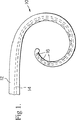
図1は本発明に従って構成された電極担持体の側面図を示し、
図2は、図1の電極担持体が補強用鞘状被覆に埋め込まれている、本発明に従って構成された電極アセンブリを示し、
図3は図2の電極アセンブリの線3−3に沿った断面図を示し、
図4は鞘状被覆が分解された後の図1の電極担持体を伴う患者の鼓室階の断面図を示し、
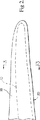
図5は本発明の第一代替実施例に従った電極担持体の側面図を示し、
図6は図5の補強用鞘状被覆に埋め込まれた電極担持体を示し、
図7は図6の電極アセンブリの線8−8に沿った断面図を示し、
図8は、補強用鞘状被覆の分解後に鼓室階で展開されている図6の電極担持体を示し、
図9は図8の電極担持体の線10−10に沿った断面図を示し、
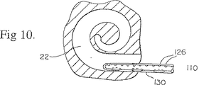
図10は鼓室階に挿入された図6の電極アセンブリの線図を示し、
図11は鼓室階で展開された図10の電極担持体の線図を示し、
図12は鼓室階から引き出される図10の電極担持体を示す。
発明の詳細な説明
図1に関して、本発明に従って構成された電極アセンブリは、シラスチック(商標)MDX44210のようなプラスチック材料から作られた長寸部材12から形成された電極担持体10を含んでいる。数本の絶縁電線(図示されていない)から形成されたケーブル14がこの長寸部材12に埋め込まれており、各絶縁電線は電極16で終端している。ケーブル14が蝸牛刺激装置(図示されていない)に接続されており、刺激パルスを蝸牛刺激装置から電極16へ伝えるのに使用される。図1で分かるように、電極16は全て剥き出しになっている。長寸部材12は弾性的であるが、形状記憶材料から作られており、その自然の形状は図示されるように螺旋形状であるようにあらかじめ湾曲されている。螺旋の湾曲は、以下でより詳細に説明されるように、人の鼓室階の湾曲、さらに詳細には蝸牛軸の湾曲に従っている。
完成後、図2に示されるように、電極担持体10を、その構成が実質的に直線的となるように、ゆがめて鞘状被覆18に埋め込むことにより、電極アセンブリ20を形成する。鞘状被覆18は、電極担持体10を図示される直線形状に維持できるように、比較的硬い材料から作られる。重要なのは、鞘状被覆18が、蝸牛液に浸されたときに溶解する又は生体再吸収性である又はさもなければ生分解性である材料から作られることである。例えば、鞘状被覆18はポリビニルアルコール(PVA)、ポリ乳酸(PLA)、ポリグリコール酸(PGA)及び他の類似の化合物から作られ得る。好適には、鞘状被覆18は、アセンブリ20が容易に移植されるように、滑らかな外表面を備えて作られる。摩擦を減らすために、コーティングがこの外表面に加えられてもよい。コーティングは、移植の間の感染から保護するために時限解除(time−released)抗菌材料から作られてもよい。鞘状被覆18は電極担持体10より硬い一方で、蝸牛の形状に合わせて曲げられ得るように、十分柔軟でなくてはならない。
電極アセンブリ20に関する断面が図3に示されている。この図3で分かるように、部材18は好適には平坦又は図8の形状になっており、電極16に垂直な平面でより容易に曲がることができる。移植直後の電極アセンブリ20の初期位置及び鞘状被覆18が分解された後の電極担持体10が図4に示されている。この図4では、電極アセンブリ20が鼓室階22に移植されて、蝸牛液24に浸されている。最初は、鞘状被覆18の硬さのために、電極アセンブリ20は大きな半径の湾曲を維持して、鼓室階22の壁25に隣接して配置されている。しかしながら、比較的短い、指定された挿入手順によって制御されることができ且つ定められるべき時間で、鞘状被覆18は蝸牛液24中で分解して電極担持体10を解放する。結果として、電極担持体10は図1に示される自然の螺旋形状をとる。この形状では、電極担持体10が蝸牛軸26に隣接して配置される。重要なのは、この後者の形状では、電極16は蝸牛軸26に面し、螺旋神経節28の限りなく近くに位置していることである。このように、電極16は、チャンネル間干渉を引き起こさずに、比較的弱い電流及び電界を発生させることができる。
さらに本発明の他の実施例が図5に示されている。この実施例においては、電極担持体110が、ほぼ環状のボデー114に形成された長寸方向に間隔を空けてある複数のフィン112を具備している。フィン112は比較的弾性的である。図5に示されるような通常の位置では、これらのフィン112は電極担持体の先端の方へ延びている。好適には、フィン112の自由端部118が長手方向に僅かに湾曲させられている。電極担持体110が図5に示されるように形成された後で、フィン112が図6に線図で示されているようにボデー114にほぼ平行に且つ隣接して配置される位置へ、フィン112が押しやられる。次に、このように変形された電極担持体110が生分解性材料状の鞘状被覆18から形成される鞘状被覆120に収められる。この第二の形状の電極担持体の断面寸法を縮小するために、ボデー114が溝を備えて形成されてもよい。例えば、電極担持体110は、第二の形状においてフィン112を収容するための溝122を備えて形成されたボデー114を含むことができる。前出の実施例の場合のように、電極担持体110はさらにボデー114に埋め込まれた接続用電線と複数の電極126を含んでいる。この実施例の利点は、図7のアセンブリが移植され且つ鞘状被覆120が分解した後で、フィン112が溝122から解放されてフィン112の自由端部118が壁25に係合し、それによって図8及び図9に示されるようにボデー114を蝸牛軸26の方へ押しやって偏変形させることである。この全過程が図10及び図11に詳細に示されている。図7に示されるように、電極担持体110及び鞘状被覆120から形成されるアセンブリ130が先ず鼓室階22に挿入される。アセンブリ130が完全に挿入された後で、鞘状被覆120は分解して、図11で分かるように鼓室階22としっかりと着座させられた電極担持体110を解放する。もしなんらかの理由で電極担持体110を図12に示される方向Aに移動することが所望されたなら、フィン112は図示されるように位置112'へ曲げ戻る。図11で分かるように、電極担持体110が、締まりばめ及びボデー114と鼓室階22の壁との間のフィン112による偏変形によって、鼓室階22に確実に着座し位置する。したがって、ボデー114が図1に示される螺旋形状に作られることもあるが、その必要はなく、電極担持体10のように形状維持する材料から作る必要もない。
本発明の好適実施例が蝸牛電極アセンブリと関連して説明されたけれども、この教示はペースメーカで使用される電極のような他の移植される電極に適用可能であることが理解されるべきである。この後出の本発明の実施においては、電極の末梢端部を内部心臓壁に取り付けるために使用される枝状物が、生体再吸収性の鞘状被覆又は他の類似の手段によって、フィン112が図6で折り畳まれる要領に類似する方法で、最初は折り畳まれて閉じた位置に維持される。移植後に、鞘状被覆は分解し、枝状物が開いて心臓壁に係合することによって、電極を定着させる。
本発明が幾つかの特定の実施例に関して説明されたけれども、これらの実施例は単に本発明の原理の適用の説明的なものにすぎないことが理解されるべきである。特定の実施においては多数の補強用鞘状被覆があってもよい。補強用鞘状被覆が配列の外面よりもむしろ配列の構造内に形成されてもよい。よって、詳細に説明された実施例は、以下の請求の範囲に関する例示的なものであって限定するものではないと考えられるべきである。FIELD OF THE INVENTION The present invention relates to an implantable device, such as a cochlear electrode, incorporating a bioresorbable or biodegradable material, and more particularly, to a preselected first suitable for insertion into a patient's body. A bioresorbable or biodegradable material having a shape, and a second shape suitable to provide a particular function or stimulus, used to change the device from the first shape to the second shape Related devices.
BACKGROUND OF THE INVENTION Although the present invention is described with reference to electrodes used in a cochlear implant device system, the present invention is equally applicable to other implantable devices. The cochlear implant system is used to rescue patients with hearing impairment. More specifically, these systems include a microphone that receives ambient sound and converts the sound into a corresponding electrical signal, signal processing means that processes the electrical signal and generates a cochlear stimulation signal, An electrode assembly for application to a patient's cochlea. It is known in the art that the cochlea is tonotopically mapped by tone. That is, the cochlea can be divided into a plurality of regions, each of which corresponds to a signal in a particular frequency range. This characteristic of the cochlea is used to provide an electrode array to the electrode assembly, each electrode being arranged and configured to deliver a cochlear stimulation signal within a preselected frequency range to the appropriate cochlear region. . The current and electric field emanating from each electrode stimulate the cilia located on the cochlea axis of the cochlea. Several electrodes may be working simultaneously. For these electrodes to work, it has been found that the magnitude of the current flowing from these electrodes and the corresponding electric field strength are a function of the distance between the electrodes and the cochlear axis. If this distance is large, the current magnitude threshold must be greater than if the distance is smaller. Furthermore, the current from each electrode may flow in all directions, and the electric fields corresponding to adjacent electrodes may partially overlap, thereby causing cross-electrode interference. In order to reduce the stimulation current magnitude threshold and eliminate cross-electrode interference, it is advisable to keep the distance between the electrode array and the cochlear axis as small as possible. This is most effectively achieved by providing the electrode array in a shape that generally follows the shape of the cochlear axis. Of course, during insertion, the electrode assembly should be substantially straight. Otherwise the insertion procedure would be too cumbersome and difficult. Although several methods and means of bending the electrode assembly have been reported, in our view none of these conventional methods are satisfactory. For example, one electrode assembly with an electrode carrier is known, which includes a longitudinal element disposed on one side thereof and configured to change its size once the assembly is inserted. I have it. For example, some of these longitudinal elements contain a hydrogel, such as PAA (polyacrylic acid), which expands after insertion by absorbing water from cochlear fluid. Alternatively, some of the longitudinal elements are shaped such that the electrode carrier can assume a linear shape at room temperature, but once exposed to body temperature, bend into a preselected shape (such as nickel / titanium). Some are). Other proposed electrode assemblies have included mechanical members arranged to bend the electrode carrier after the electrode carrier has been inserted. All of these prior art devices require structures that are difficult and expensive to manufacture and that cannot be expected to function satisfactorily in most cases.
SUMMARY OF THE INVENTION In view of the above-mentioned deficiencies of the prior art, a first shape that is relatively straight so that it can be easily implanted, and a second shape that is curved to fit the patient's cochlea. It is an object of the present invention to provide a cochlear electrode assembly having a dual configuration and using a material that degrades or dissociates in body fluids. A further object is to provide an assembly having relatively few elements such that the cross section is not too large for implantation. Another object is to provide an assembly that can be manufactured relatively easily and inexpensively. Other objects and advantages of the present invention will become apparent from the following description. Briefly, an electrode assembly configured in accordance with a preferred embodiment of the present invention comprises an electrode configured and arranged to support a plurality of electrodes suitable for defining an electrode array for applying a cochlear stimulation signal. A carrier is included. The electrode carrier is preferably pre-shaped into a selected curved shape to ensure that the electrode is positioned very close to the cochlear axis of the scala tympani. Prior to implantation, the electrode carrier is embedded in a relatively linear sheath. The sheath is preferably made of a bioresorbable material, such as a polymer that degrades in cochlear fluid after implantation. Alternatively, the sheath is formed from a material that dissociates otherwise after implantation. Preferably, the electrode carrier is provided with a partially deformed fin that is bent linearly with respect to the electrode carrier. Once the sheath is disassembled, the deformed fins bend outwardly away from the electrode carrier and engage the wall of the scala tympani to press the electrode carrier toward the cochlear axis. Alternatively, the electrode carrier is formed in advance so that the electrode carrier takes a curved shape after the sheath-shaped coating is decomposed.
[Brief description of the drawings]
FIG. 1 shows a side view of an electrode carrier constructed according to the invention,
FIG. 2 shows an electrode assembly constructed in accordance with the present invention, wherein the electrode carrier of FIG. 1 is embedded in a reinforcing sheath;
FIG. 3 shows a cross-sectional view of the electrode assembly of FIG. 2 along line 3-3;
FIG. 4 shows a sectional view of the patient's tympanic floor with the electrode carrier of FIG. 1 after the sheath coating has been disassembled;
FIG. 5 shows a side view of an electrode carrier according to a first alternative embodiment of the invention,
FIG. 6 shows an electrode carrier embedded in the reinforcing sheath coating of FIG. 5,
FIG. 7 shows a cross-sectional view of the electrode assembly of FIG. 6 along line 8-8;
FIG. 8 shows the electrode carrier of FIG. 6 deployed on the tympanic floor after disassembly of the sheath sheath for reinforcement,
FIG. 9 shows a cross-sectional view of the electrode carrier of FIG. 8 along the line 10-10,
FIG. 10 shows a diagram of the electrode assembly of FIG. 6 inserted into the tympanic floor;
FIG. 11 shows a diagram of the electrode carrier of FIG. 10 deployed on the tympanic floor,
FIG. 12 shows the electrode carrier of FIG. 10 pulled out of the tympanic floor.
DETAILED DESCRIPTION OF THE INVENTION With reference to FIG. 1, an electrode assembly constructed in accordance with the present invention includes an
After completion, as shown in FIG. 2, the
A cross section for the
Still another embodiment of the present invention is shown in FIG. In this embodiment, the
Although the preferred embodiment of the present invention has been described in connection with a cochlear electrode assembly, it should be understood that the teachings are applicable to other implanted electrodes, such as those used in pacemakers. . In the practice of the invention described below, the branches used to attach the distal end of the electrode to the internal heart wall may be provided with a
Although the invention has been described with respect to certain specific embodiments, it is to be understood that these embodiments are merely illustrative of the application of the principles of the present invention. In certain implementations, there may be multiple reinforcing sheaths. A reinforcing sheath may be formed within the structure of the array rather than the outer surfaces of the array. Therefore, the embodiments described in detail are to be considered as illustrative and not limiting with respect to the following claims.
Claims (13)
前記長寸部材を前記第一形状へ変形するように選択され た形状を有し、前記長寸部材を覆う鞘状被覆とを備え、
前記鞘状被覆が前記第一の材料よりも硬い第二の材料か ら形成されており、体内に移植した後に前記鞘状被覆が 分解して、前記長寸部材が前記第二の形状をとれるよう に前記第二の材料が体液に溶解可能である、蝸牛移植装置。 It is formed from a flexible first material, a Nagasun member in which a plurality of electrodes are attached, and the first shape selected for insertion into a patient's body, preselected by the electrodes An elongated member having a second shape suitable for applying treatment ;
A sheath having a shape selected to deform the elongate member to the first shape and covering the elongate member;
Wherein is formed harder second material or et than sheath covering said first material, and decomposing said sheath coating after implanted in the body, the length dimension member can take the second shape It said second material is soluble in body fluids, cochlear implant device as.
前記電極担持体に取り付けられた複数の電極と、
前記蝸牛への挿入で分解して前記ボデーが前記第二の形状をとることを可能にする生体再吸収性材料から作られ、前記弾性ボデーよりも硬く、前記ボデーを前記第一の形状にするために前記電極担持体周りに配置された補強用鞘状被覆とを備える、蝸牛移植電極アセンブリ。 A first shape suitable for insertion into a patient's cochlea, and an elongate electrode carrier having an elastic body having a second shape which is curved to conform to the surface of the cochlea,
A plurality of electrodes attached to the electrode carrier,
It made from bioresorbable material that allows the body decomposes at insertion into the cochlea takes the second shape, harder than the elastic body and the body to the first shape wherein comprising an electrode carrier reinforcing sheath covering disposed around cochlear implant electrode assembly for.
前記ボデーを形成するステップと、Forming the body;
前記ボデーを前記第一の形状にするステップと、Making the body into the first shape;
生体再吸収性材料から作られている鞘状被覆を前記ボデA sheath made of bioresorbable material is applied to the body. ー周りに付加するステップとを含み、-Adding around
前記治療装置を患者に挿入したときに、前記鞘状被覆がWhen the treatment device is inserted into a patient, the sheath covers 分解して、前記ボデーが前記第二の形状をとれるようにDisassembled so that the body can take the second shape した、治療装置を作る方法。How to make a treatment device.
Applications Claiming Priority (1)
| Application Number | Priority Date | Filing Date | Title |
|---|---|---|---|
| PCT/AU1995/000622 WO1997010784A1 (en) | 1995-09-20 | 1995-09-20 | Bioresorbable polymer use in cochlear and other implants |
Publications (2)
| Publication Number | Publication Date |
|---|---|
| JPH11514252A JPH11514252A (en) | 1999-12-07 |
| JP3576563B2 true JP3576563B2 (en) | 2004-10-13 |
Family
ID=27761762
Family Applications (1)
| Application Number | Title | Priority Date | Filing Date |
|---|---|---|---|
| JP50603097A Expired - Fee Related JP3576563B2 (en) | 1995-09-20 | 1995-09-20 | Use of bioresorbable polymers in cochlear and other organ implantation devices |
Country Status (3)
| Country | Link |
|---|---|
| EP (1) | EP0971660B1 (en) |
| JP (1) | JP3576563B2 (en) |
| DE (1) | DE69533455T2 (en) |
Families Citing this family (14)
| Publication number | Priority date | Publication date | Assignee | Title |
|---|---|---|---|---|
| ATE468150T1 (en) * | 2000-10-04 | 2010-06-15 | Cochlear Ltd | COMBINATION OF STYLET AND STIFFENING SHEATH IN AN IMPLANTABLE STIMULATING DEVICE, ESPECIALLY IN A COCHLEAR IMPLANT |
| CA2382894A1 (en) * | 2000-10-11 | 2002-04-18 | Cochlear Limited | Double stylet insertion tool for a cochlear implant electrode array |
| AUPR148400A0 (en) | 2000-11-14 | 2000-12-07 | Cochlear Limited | Apparatus for delivery of pharmaceuticals to the cochlea |
| US9089450B2 (en) | 2000-11-14 | 2015-07-28 | Cochlear Limited | Implantatable component having an accessible lumen and a drug release capsule for introduction into same |
| WO2004050056A1 (en) | 2002-11-29 | 2004-06-17 | Cochlear Limited | Cochlear implant drug delivery device |
| US7949412B1 (en) | 2005-06-02 | 2011-05-24 | Advanced Bionics, Llc | Coated electrode array having uncoated electrode contacts |
| US8133215B2 (en) | 2007-08-13 | 2012-03-13 | Cochlear Limited | Independently-manufactured drug delivery module and corresponding receptacle in an implantable medical device |
| US8271101B2 (en) | 2007-08-29 | 2012-09-18 | Advanced Bionics | Modular drug delivery system for minimizing trauma during and after insertion of a cochlear lead |
| US8190271B2 (en) | 2007-08-29 | 2012-05-29 | Advanced Bionics, Llc | Minimizing trauma during and after insertion of a cochlear lead |
| CN104224171B (en) | 2010-03-17 | 2017-06-09 | 伊利诺伊大学评议会 | Implantable bio-medical instrument based on biological absorbable matrix |
| US8617097B2 (en) | 2010-05-24 | 2013-12-31 | Cochlear Limited | Drug-delivery accessory for an implantable medical device |
| WO2013089867A2 (en) | 2011-12-01 | 2013-06-20 | The Board Of Trustees Of The University Of Illinois | Transient devices designed to undergo programmable transformations |
| WO2015057794A1 (en) * | 2013-10-15 | 2015-04-23 | Med-El Elektromedizinische Geraete Gmbh | Deployable and multi-sectional hearing implant electrode |
| US10925543B2 (en) | 2015-11-11 | 2021-02-23 | The Board Of Trustees Of The University Of Illinois | Bioresorbable silicon electronics for transient implants |
Family Cites Families (4)
| Publication number | Priority date | Publication date | Assignee | Title |
|---|---|---|---|---|
| NL6709780A (en) * | 1967-07-14 | 1969-01-16 | ||
| DK141034B (en) * | 1977-11-22 | 1979-12-31 | C C Hansen | ELECTRODE FOR INSERTING IN THE SNAIL OF THE CITY (COCHLEA) |
| SE8103903L (en) * | 1981-06-22 | 1982-12-23 | Medline Ab | DEVICE FOR CONNECTING BODY CHANNELS |
| US5578084A (en) * | 1991-09-27 | 1996-11-26 | Cochlear Ltd. | Self-curving cochlear electrode array |
-
1995
- 1995-09-20 EP EP95933229A patent/EP0971660B1/en not_active Expired - Lifetime
- 1995-09-20 JP JP50603097A patent/JP3576563B2/en not_active Expired - Fee Related
- 1995-09-20 DE DE69533455T patent/DE69533455T2/en not_active Expired - Lifetime
Also Published As
| Publication number | Publication date |
|---|---|
| EP0971660A4 (en) | 2000-02-02 |
| EP0971660A1 (en) | 2000-01-19 |
| EP0971660B1 (en) | 2004-09-01 |
| DE69533455D1 (en) | 2004-10-07 |
| JPH11514252A (en) | 1999-12-07 |
| DE69533455T2 (en) | 2005-09-01 |
Similar Documents
| Publication | Publication Date | Title |
|---|---|---|
| CA2230595C (en) | Bioresorbable polymer use in cochlear and other implants | |
| EP0662853B1 (en) | An implantable lead | |
| CA2374037C (en) | A cochlear implant electrode array | |
| JP3576563B2 (en) | Use of bioresorbable polymers in cochlear and other organ implantation devices | |
| US6374143B1 (en) | Modiolar hugging electrode array | |
| JP4018156B2 (en) | Implanted cochlear stimulator implanted around the cochlea axis by reverse placement | |
| JP3971996B2 (en) | Pre-curved cochlear implant electrode array | |
| CA2119358C (en) | Self-curving cochlear electrode array | |
| EP3062743B1 (en) | Stimulating assembly fixation features | |
| US20040116995A1 (en) | Curved cochlear implant electrode array | |
| JP2004509730A (en) | Dual stylet insert for cochlear implant electrode row | |
| WO2002032498A1 (en) | Insertion tool for a cochlear implant electrode array | |
| JPS6111115B2 (en) | ||
| JP2004509727A (en) | Cochlear electrode array for implantation | |
| AU2002237109A1 (en) | Curved cochlear implant electrode array |
Legal Events
| Date | Code | Title | Description |
|---|---|---|---|
| TRDD | Decision of grant or rejection written | ||
| A01 | Written decision to grant a patent or to grant a registration (utility model) |
Free format text: JAPANESE INTERMEDIATE CODE: A01 Effective date: 20040608 |
|
| A61 | First payment of annual fees (during grant procedure) |
Free format text: JAPANESE INTERMEDIATE CODE: A61 Effective date: 20040708 |
|
| R150 | Certificate of patent or registration of utility model |
Free format text: JAPANESE INTERMEDIATE CODE: R150 |
|
| FPAY | Renewal fee payment (event date is renewal date of database) |
Free format text: PAYMENT UNTIL: 20080716 Year of fee payment: 4 |
|
| FPAY | Renewal fee payment (event date is renewal date of database) |
Free format text: PAYMENT UNTIL: 20080716 Year of fee payment: 4 |
|
| FPAY | Renewal fee payment (event date is renewal date of database) |
Free format text: PAYMENT UNTIL: 20090716 Year of fee payment: 5 |
|
| LAPS | Cancellation because of no payment of annual fees |