JP3575953B2 - Disc music box - Google Patents
Disc music box Download PDFInfo
- Publication number
- JP3575953B2 JP3575953B2 JP16760197A JP16760197A JP3575953B2 JP 3575953 B2 JP3575953 B2 JP 3575953B2 JP 16760197 A JP16760197 A JP 16760197A JP 16760197 A JP16760197 A JP 16760197A JP 3575953 B2 JP3575953 B2 JP 3575953B2
- Authority
- JP
- Japan
- Prior art keywords
- disc
- music box
- disk
- turn plate
- playing
- Prior art date
- Legal status (The legal status is an assumption and is not a legal conclusion. Google has not performed a legal analysis and makes no representation as to the accuracy of the status listed.)
- Expired - Fee Related
Links
- 238000001514 detection method Methods 0.000 claims description 56
- 230000000452 restraining effect Effects 0.000 claims description 6
- 210000000078 claw Anatomy 0.000 description 29
- 230000001629 suppression Effects 0.000 description 8
- 230000002093 peripheral effect Effects 0.000 description 5
- 230000005540 biological transmission Effects 0.000 description 4
- 238000004519 manufacturing process Methods 0.000 description 4
- 230000000694 effects Effects 0.000 description 3
- 239000002184 metal Substances 0.000 description 3
- 238000000034 method Methods 0.000 description 3
- 230000002829 reductive effect Effects 0.000 description 3
- 238000010586 diagram Methods 0.000 description 2
- 230000002401 inhibitory effect Effects 0.000 description 2
- 239000000463 material Substances 0.000 description 2
- 230000003287 optical effect Effects 0.000 description 2
- 238000002360 preparation method Methods 0.000 description 2
- 229920003002 synthetic resin Polymers 0.000 description 2
- 239000000057 synthetic resin Substances 0.000 description 2
- 238000012356 Product development Methods 0.000 description 1
- 230000001154 acute effect Effects 0.000 description 1
- 238000009826 distribution Methods 0.000 description 1
- 230000005764 inhibitory process Effects 0.000 description 1
- 239000007769 metal material Substances 0.000 description 1
- NJPPVKZQTLUDBO-UHFFFAOYSA-N novaluron Chemical compound C1=C(Cl)C(OC(F)(F)C(OC(F)(F)F)F)=CC=C1NC(=O)NC(=O)C1=C(F)C=CC=C1F NJPPVKZQTLUDBO-UHFFFAOYSA-N 0.000 description 1
- 239000011295 pitch Substances 0.000 description 1
- 238000003825 pressing Methods 0.000 description 1
- 230000002441 reversible effect Effects 0.000 description 1
- 238000000926 separation method Methods 0.000 description 1
- 238000004904 shortening Methods 0.000 description 1
- 229910001220 stainless steel Inorganic materials 0.000 description 1
- 239000010935 stainless steel Substances 0.000 description 1
Images


Landscapes
- Automatic Disk Changers (AREA)
- Toys (AREA)
Description
【0001】
【発明の属する技術分野】
本発明は、所定の演奏パターンに複数の演奏係合部を設けたオルゴールディスクを、モータにより回転駆動し、所定の演奏タイミングで、スターホイールを演奏係合部が係合して回転させ、スターホイールよりオルゴール弁を弾いて、メロディを奏でるディスクオルゴールに関し、使用者が、単一曲及び複数曲を記録したディスクを選択した場合にも、各曲毎に正確に演奏開始、停止が行えるようにした。
【0002】
【従来の技術】
一般に、時計等の報知に用いられる発音手段としては、発音回路及びスピーカ等を用いて、無機的な電子音を得るものに限らず、機械的なオルゴールを用いて、柔らかく古風なオルゴール音を得るようにしたものが知られている。
【0003】
このようなオルゴールは、単一の曲目をオルゴール演奏するものが一般的であり、この音程に応じた複数の発音部分を備えた長板状の発音体と、この発音体に対向配置され所定の演奏タイミングで発音体の発音部分を爪弾く突起が突設されたドラム体と、このドラム体を一定速度で回転駆動する駆動部とから構成されている。
【0004】
すなわち、この発音体は、略長板状の金属板を、音階数に応じた所定数の発音部分であるクシ歯状に形成され、これらクシ歯部分(オルゴール弁)は、所定の長さ且つ厚さに形成され、このオルゴール弁の先端が爪弾かれた場合には、分担する音階のオルゴール音が発生するようにしている。また、ドラム体は、少なくとも発音体より長い円筒状に形成され、発音体の発音部位に対峙して回転可能に配設され、発音体の発音部分に対応した外周には、曲目に合わせて間歇的な突起が形成されている。そして、駆動部が、ドラム体を一定方向に所定スピードで回転駆動することにより、所定のタイミングでドラム体の各突起が、発音体の各発音部位を爪弾くことにより、曲目をオルゴール演奏している。
【0005】
また、このような予め組込まれたドラム体の替わりに、異なる曲目が記録された複数のオルゴールディスクを、交換可能に構成し、任意の曲目をオルゴール演奏できるようにしたオルゴールも、提案されている。
【0006】
このオルゴールディスクは、円盤状に形成され、該オルゴールディスクの一面を発音体のオルゴール弁に応じて複数トラックに区画し、そのトラックが分担した音階の演奏タイミングに応じた周方向の箇所に演奏用係合部を形成した構成を備え、これらの演奏用係合部は、オルゴールディスクの所定箇所に設けた突起や所定径の孔により構成されている。そして、このような演奏用係合部を用いて、発音体の所定部位を、爪弾くことによって、オルゴール演奏が行われる。
【0007】
すなわち、このオルゴールディスクを用いるオルゴールは、多数の演奏用係合部を備えた円板状のオルゴールディスクを装着してオルゴール演奏するものであって、オルゴールディスクはオルゴール本体部の駆動機構により回転駆動され、他方、オルゴール本体部には、発音体のオルゴール弁を弾くスターホイールを、スターホイール軸に回転可能に装着している。そして、駆動機構によりオルゴールディスクを回転させると、オルゴールディスクの演奏用係合部が該演奏用係合部に対応するスターホイールの爪を引っ掛けて該スターホイールを回転させ、この回転するスターホイールに後続する他の爪により、所定のタイミングで所定音階のオルゴール弁を弾いてオルゴール音を生成し、メロディを奏でることができる。
【0008】
また、このディスクオルゴールは、スターホイールに対向する部位のオルゴールディスクを、押えローラを備えたオルゴールディスク押えアームで片側面から押圧して保持することにより、比較的に薄い厚さのオルゴールディスクを用いることができる。従って、異なる曲目パターンが形成されたオルゴールディスクを、多数、廉価に制作することができるとともに、オルゴールディスク自体が薄板円盤状なので、CDサイズのメディアと同様に、収納、保管も容易に行え、効率的に輸送することができ、効率的な商品流通が図れる。
【0009】
更に、このようにオルゴールディスク自体の取扱が容易なので、オルゴールに着脱することも簡易に行え、短時間にオルゴールディスク交換できる。従って、予め異なる曲目のオルゴールディスクを複数枚、用意しておき、これらのオルゴールディスクから任意の曲目を選択してオルゴールディスク交換することにより、オルゴール演奏する曲目変更を迅速且つ容易に行うことができる。
【0010】
このように、ディスクオルゴールは、ドラム固定型の1曲専用のオルゴールに比べて、複数のオルゴールディスクから任意のオルゴールディスクを選択して簡単に装着できるので、曲目の変更が柔軟且つ容易に行える利点を有している。
【0011】
【発明が解決しようとする課題】
このようなディスクオルゴールにおいて、基本的に、1ディスクを回転動作させて、オルゴール演奏させていたので、演奏曲目等に制約が生じていた。特に、例えば、このようなオルゴールディスクを、時計に組込んだ場合には、報時動作毎に、自動的に異なる曲目をオルゴール演奏できないという不都合が生じ、商品展開を狭めていた。
【0012】
すなわち、ディスクオルゴールを時計に組込んで報時動作を行う従来のものは、正時信号が入力するとオルゴール機構のモータを発進駆動し、ディスクが1回転するとオートストップ機構が働いて停止する。このような従来のものは、演奏時間を短くしたり、また、長くしたいという要望に適合し難い不都合がある。
【0013】
そこで、本発明は、この種のディスクオルゴールにおいて、演奏時間を短くしたり、また、長くすることの可能なディスクオルゴールを提案するものである。
【0014】
【課題を解決するための手段】
本願第1請求項の発明は、演奏用の凸部又は孔部による演奏用係合部を備えた交換可能なオルゴールディスクを、前記ディスクの中央部を支持するターンプレートによって回転駆動し、前記ディスクの演奏用係合部に案内されて回転するスターホイールにより、オルゴール弁を弾いてメロディを奏でるディスクオルゴールにおいて、
複数のディスク回転位置検出手段を設けるとともに、前記回転位置検出手段からの検出信号を、選択的に抑制する抑止手段を設けて構成され、
前記回転位置検出手段は、前記ターンプレートの周上に、所定間隔で設けられた複数の切欠き部と、該ターンプレートの切欠き部によって操作されるスイッチとから構成され、
前記抑止手段は、前記ターンプレートの周上に設けたディスクオルゴールである。
【0015】
本願第2請求項の発明は、請求項1の発明において、前記抑止手段を、前記切欠き部内に配置されるディスクに設けた突設部によって構成したディスクオルゴールである。
【0016】
本願第3請求項の発明は、請求項1の発明において、前記回転位置検出手段からの検出信号に基づき、ディスクの回転駆動を停止するディスク駆動停止手段を設けるとともに、
外部スイッチからのスイッチ信号に基づき、前記回転位置検出手段からの検出信号を、選択的に抑制する抑止手段を設け、
該外部スイッチの操作によって、ディスク駆動停止手段の停止動作を制御した構成のディスクオルゴールである。
【0017】
従って、本発明によれば、演奏時間を短くしたり、また、長くすることの可能なディスクオルゴールを得ることができる。この演奏時間の選択も、請求項2に記載したように、ディスクの所定の回転位置検出を阻止する突設部を設けたディスクにより行う構造的な態様や、請求項3に記載したように、外部スイッチによる検出信号の抑止によって行う電気的な態様を採ることができる。
【0018】
【発明の実施の形態】
以下に、本発明のディスクオルゴールに係る第1具体例を図1ないし図11に基づいて説明する。
【0019】
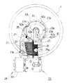
図1及び図2に示すように、本例の本例のディスクオルゴール20は、容易且つすばやく交換することの可能なオルゴールディスク1(以降、ディスク1と称する)を用いて、オルゴール演奏するものである。
【0020】
本例のディスクオルゴール20に用いるディスク1は、ステンレス等の軽金属を用いて所定の剛性強度を備えた円盤形状に形成され、その裏面に曲目パターンに応じた複数の演奏用係合部3が設けられている。更に、図3に示すように、ディスク1は、その中心に所定の内径を備えた円形状の装着孔2が設けられ、この装着孔2の近傍且つ演奏パターンに応じた角度位置には、ディスク回転駆動制御に用いられる駆動孔4が設けられている。この駆動孔4を用いて行うディスク回転駆動制御については後述する。
【0021】
また、このディスク1の裏面は、後述するオルゴール20のオルゴール発音体27のオルゴール弁27aに相応して、径方向に複数トラックに区画されており、各トラックが分担した音階の演奏タイミングに応じた周方向の箇所には、演奏用係合部3が形成され、これらの演奏用係合部3により、所定の演奏パターンを構成している。
【0022】
また、この演奏用係合部3は、本例においては、突起タイプのものが用いられており、金属製ディスク1の該当箇所を切り起こして突起6を形成し、この突起6を発音動作用の係合部駆動2としている。すなわち、略長方形のコ字形状に切り込み6aを形成し(図4(1))、この切り込み6aを押圧して切り起こし部6bに成形し(図4(2))、更にこの切り起こし部6bを中間で折り曲げて、所定高さにディスク1背面から突出した突起6を形成している(図4(3))。また、このような演奏用係合部3は、自動的な加工機械により、ディスク1の内周側から外周側に向って、順次、形成されている。従って、このように演奏用係合部3を形成しているので、簡易な製作治具、製作工程で容易に、多数のディスク1を製作することができる。
【0023】
このようなディスク1を用いるディスクオルゴール20は、略平板素材を用いて所定の平面形状に形成されたベース台21と、このベース台21上に立設された中心軸22に回転可能に遊嵌されたターンプレート23と、このターンプレート23にディスク1を脱着可能に保持する保持アーム25と、ターンプレート23を一定速度で回転駆動する駆動機構24と、このターンプレート23に同行して回転駆動されるディスク1の各演奏用係合部3により、対応した各スターホイール26を介して、発音駆動されるオルゴール発音体27とから構成されている。
【0024】
すなわち、このベース台21は、剛性強度が高い素材を用いて、少なくとも、ディスク1半径の長さより長く形成され、その長手方向の一端に、ディスク1を保持するターンプレート23を立設して回転可能に軸支する一方、他端に、駆動機構24のモータMを配設するとともに、これらの間に、オルゴール演奏時にモータ回転駆動力をターンプレート23に減速して伝達する駆動機構24の伝達軸及び歯車を配設して構成されている。また、このベース台21の所定箇所には、ディスクオルゴール20を時計等の本体ケースに取付けるねじ孔が設けられている。
【0025】
このターンプレート23は、ベース台21に立設された金属製の中心軸22に遊嵌されるとともに、ターンプレート23の先端側には、Eリングが嵌着されて抜け止めが図られている。
【0026】
また、このターンプレート23は、合成樹脂を用いて、厚板円盤状に形成され、その先端側には、ディスク1の内径に応じた外径の装着部23aが、中間には、この装着部23aよりも大径でディスク1の下面を支持する支持部23bが、また、基端側には、駆動機構の出力歯車に噛合された歯車部23cが、それぞれ設けられており、更に、ディスク1の前記駆動孔4に対応する位置のターンプレート23には、駆動突起部23dが突設されている。尚、図中、29はベース台21に固定された所定高さの支持部材であり、この支持部材29によって、ディスク1の外周側の下面を支持して、ディスク1を安定して回転駆動できるようにしている。
【0027】
更に、ターンプレート23は、駆動機構24に接続され、この駆動機構24により、オルゴール演奏時には、ターンプレート23を、一定回転方向に一定速度で回転駆動するようにしている。
【0028】
この駆動機構24は、図5に示すように、ターンプレート23にディスク1が装着されたときに該ディスク1の外側に位置するモータMと、このモータ回転出力をターンプレート23に減速しつつ伝達する第1入力歯車32、伝達軸33、第1出力歯車34、第2歯車35とから構成されている。以下、各部を詳述する。
【0029】
モータMは、DCモータが用いられ、ディスク1の外方に、そのモータ軸を、ベース台21の平面と平行に、且つ、保持アーム25の長手方向と直交して、ベース台21の固定されている。従って、モータMをベース台21の平面に、安定して保持できるとともに、ほぼ最小限、モータ径程度の高さに、ディスクオルゴール20の厚さを収めることができるので、薄型化を図ることができる。
【0030】
また、このモータMの接続端子は、図示を省略したモータ駆動回路に接続され、このモータ駆動回路から、供給される駆動電流により、動作するように構成されている。
【0031】
モータMの出力軸には、ウォームギア31が固着され、このウォームギア31には、第1入力歯車32が噛合している。この第1入力歯車32は、このモータ出力軸の長手方向と直交し、且つスターホイール軸26Aと平行に軸支された伝達軸33の一端に固着され、この伝達軸33の他端には、第1出力歯車34が固着されている。この第1出力歯車34は、第2歯車35の入力歯車部35aに噛合し、この第2歯車35に一体に形成された出力歯車部35bは、ターンプレート23の基端に一体に形成された歯車部23cに噛合している。
【0032】
前記第2歯車35は、互いに直交する回転面を有する入力歯車部35a,出力歯車部35bを一体に備えており、その入力歯車部35aが、略円板上の外周縁を軸方向に突設するとともに、この突設された端面に歯部が刻設されて形成され、第1出力歯車34に噛合している。また、この第2歯車35の出力歯車部35bは、入力歯車部35aと同軸且つ内周に、所定外径の外歯状に形成され、ターンプレート23の基端に一体に形成された歯車部23cに、噛合している。従って、第1入出力歯車の回転を、該回転軸に直交する方向に、ベース台21上に設けられたターンプレート23に減速しつつ伝達するようにしている。
【0033】
更に、これらの互いに噛合する各歯車31,32,34,34,23c間には、所定の減速比が設定されている。
【0034】
従って、この駆動機構24により、モータMの回転駆動力は、所定速度に減速されつつターンプレート23に伝達され、このターンプレート23に装着されたディスク1を所定の回転速度で回転させる。
【0035】
また、再び図1及び図2に示すように、保持アーム25は、少なくとも前記ディスク1の半径長さよりも長い略長板形状に形成され、その基端がベース台21に軸支され、先端が同ベース台21に立設された中心軸22に、係合ロック可能に構成され、装着したディスク1を、ベース台21側のスターホイール26に回転しながら押圧するローラ25aを備えている。
【0036】
すなわち、中心軸22先端の保持アーム25が係合する箇所には、切欠き部22aが設けられる一方、この切欠き部22aに応じて、保持アーム25の該当箇所には、所定形状のロックアーム25bが設けられ、このロックアーム25bは、その先端が、切欠き部22aに係合するようにバネ付勢されている。
【0037】
従って、使用者がロックアーム25bの係合を解除する操作を行わない限り、ディスク1は確実にオルゴール20に装着されて保持され、オルゴール20自体の姿勢に拘らず、ディスク1を安定保持して、オルゴール演奏できるようにしている。他方、このような保持アーム25のロックを解除し、保持アーム25をスイングして起立させることにより、迅速且つ容易に、ディスク1の交換を行うことができる。
【0038】
図1及び図2において、オルゴール発音動作するオルゴール発音体27は、金属素材を用いて長板形状に形成され、ベース台21にディスク1と平行になるように配設されている。オルゴール発音体27の一端側の先端は、クシ歯状形成されたオルゴール弁部27aが設けられ、オルゴール弁部27a側の端部が、保持アーム25に対応したディスク1の半径方向に揃うように、他端側の基端が、ベース台21に設けられた台座部に固定されている。また、これらのオルゴール弁部27a,27aは、発音する音階数に応じた所定数が設けられ、それぞれが、音階に応じた所定の厚さ及び長さに形成され、これらのオルゴール弁部27a,27aの先端が弾かれると、所定の音階/音程のオルゴール音を生成するように設けられている。
【0039】
そして、保持アーム25に対応したディスク1下面側の箇所には、ディスク1の音階トラック数に応じた複数のスターホイール26が、スターホイール軸26Aにより、回転可能に軸支されている。
【0040】
このスターホイール26は、どのような回転位置でも、ディスク1の係合突部に係合できるように、8つの爪部が設けられており、これらの爪部の回転方向における前側は、鋭角なスロープ面に形成される一方、後側は、回転方向に直交する面に形成されて、ディスク1の係合突部との係合を確実に行えるように設けられている。
【0041】
従って、演奏係合部として、穴を設けたタイプに比べて、全てのスターホイールの爪を一列に揃える整列動作や、穴に確実に係合するように回転方向にスターホイールを回転付勢する必要が無くなり、構成的に簡素化することができる。
【0042】
また、各スターホイール26に対峙したベース台21の箇所には、摩擦を低減できる合成樹脂を用いて、スターホイール26と同数に所定幅の間隙部を有した離間部材が設けられ、各スターホイール26のスターホイール軸長手方向に沿った所定の間隔に保持するようにしている。従って、各スターホイール26は、それぞれ、回転可能に、対応したオルゴール発音体27のオルゴール弁部27aに、常に対峙した位置を維持できるようにしている。
【0043】
そして、使用者が、ベース台21に任意に選択したディスク1を装着し、図示を省略した制御回路から正時等に起動信号が出力されたり、同様に図示を省略したモニタースイッチを、使用者がオン操作すると、駆動機構24によりディスク1が回転駆動され、曲目の音階に応じたオルゴール弁部27aが、所定のタイミングで、スターホイール26の爪部26aにより爪弾かれ、オルゴール演奏が行われる。
【0044】
すなわち、ディスク1の各演奏用係合部3の突起が、該演奏用係合部3に対応するスターホイール26の爪部26aを引っ掛けて、該スターホイール26を強制的に回転させ、この回転するスターホイール26の後続する他の爪部26aにより、最終的にオルゴール弁部27aが弾かれ、オルゴール音が発生する。
【0045】
これは、ディスク1が回転駆動され(図6(1))、演奏用係合部3がスターホイール26の爪部26aのうち、例えば爪部26aと係合する(図6(2))と、該爪部26aは演奏用係合部3の突起6により強制的に移動され、スターホイール26が回転させられる。このとき、スターホイール26の爪部26aに後続する爪部26aがオルゴール弁部27aと当接し(図6(3))、更に回転移動してオルゴール弁部27aを爪弾いて(図6(4))、この結果、当該オルゴール弁部27aの固有な音階のオルゴール音が発生する。
【0046】
更に、本例では、使用者が、単一の曲目が記録されたディスク1を選択した場合のみならず、演奏時間が異なる複数の曲目を記録したディスク1を選択した場合にも、順次、各曲目毎に異なる演奏時間のオルゴール演奏動作を正確に行えるようにしている。
【0047】
すなわち、従来のディスクオルゴール20は、単一の曲目を演奏するディスク1の1回転で自動的にオルゴール演奏を停止するオートストップ機構が設けられているが、本例においては、このオートストップ機構と異なり、単一のディスク1に記録された複数の曲目に応じた、ディスク1回転途中の複数位置で、ディスク1を停止動作し、順次、曲目をオルゴール演奏できるようにしたものであり、且つ、単一曲目ディスクの場合には、正常なディスク1回転動作を行えるようにしている。
【0048】
この複数曲目に応じてオルゴール演奏時間を正確に制御するディスク回転位置検出手段41は、図7及び図8に示すように、ターンプレート23に設けられた複数の切欠き部42と、ベース台21の所定箇所に配設され、回転移動してきた切欠き部42を検出するマイクロスイッチ43とから構成され、このマイクロスイッチ43の検出動作を選択的に抑制する抑止手段は、ディスク1側に設けられ任意箇所の切欠き部42内に突出配置された爪部7から構成されている。
【0049】
この切欠き部42は、単一曲目の場合に、その演奏開始及び演奏終了位置を規定し、複数曲目の場合に、その第1曲目の演奏開始及び演奏終了位置を規定する基準切欠き部42aと、この基準切欠き部42aを設けた位置を起点とし、予め設定された単位時間に応じて、周方向に所定間隔を設けて形成された複数の単位切欠き部42bとから構成されている。
【0050】
これらの基準切欠き部42a及び単位切欠き部42bは、ターンプレート23の支持部23bの外周で、且つ前述した条件を満たす位置において、周方向に所定の長さを設けて形成され、マイクロスイッチ43による検出を確実にするようにしている。
【0051】
これは、ターンプレート23に設けた駆動突起部23bに、ディスク1の駆動孔4を係合させて、ディスク1をターンプレート23に装着しているので、常に、ターンプレート23に対して、同一の回転角度位置で、ディスク1がターンプレート23に装着されることになる。
【0052】
従って、単一曲目ディスク1の場合には、ベース台21に対して、そのディスク1の演奏開始及び演奏終了位置は、常に同一となり、複数曲目ディスク1の場合にも、ベース台21に対して、その第1曲目の演奏開始及び演奏終了位置は、常に、同一となる。
【0053】
そして、これにより、ターンプレート23の基準切欠き部42aを設ける位置と、ベース台21側のマイクロスイッチ43を設置する位置とは、互いに上下方向に一致した場合に、ディスク1の回転位置が、単一曲目及び複数曲目でも、その開始曲の演奏開始及び演奏終了位置になるように設定されている。
【0054】
また、単位切欠き部42bは、基準切欠き部42aを設けたターンプレート23の箇所を起点として、予め定められた演奏単位時間に応じて、ターンプレート23の外周における周方向に同一な所定距離を設けて、順次、複数、設けられている。
【0055】
尚、本例においては、均等な間隔で、単位切欠き部42bが3つ設けられており、これは、例えば、ディスク1の1回転動作が1分間の場合に、各演奏単位時間が約15秒間となるように設定されている。
【0056】
更に、このマイクロスイッチ43は、図9(1)に示すように、スイッチ本体の上部に、ピン状のスイッチレバー43aを備え、このスイッチレバー43aは、その基端をスイッチ本体に回転可能に支持されるとともに、その先端が上方に向くようにバネ等により、付勢されている。
【0057】
また、マイクロスイッチ43とターンプレート23の支持部23bの下面との距離は、そのスイッチレバー43aの全長よりも短く、つまり、オルゴールの演奏途中の回転位置では、スイッチレバー43aが、支持部23bの下面に当接して倒される距離に設定されている。
【0058】
そして、このマイクロスイッチ43内部には、スイッチレバー43aに連動して、検出信号を送出する接点構造等が収納されている。
【0059】
また、このマイクロスイッチ43は、通常とは逆転動作し、スイッチレバー43aが倒された場合に、オフ信号を出力する一方、スイッチレバー43aが起立した場合に、オン信号を出力するように動作が設定されている。尚、これに限らず、通常設定のマイクロスイッチ43の出力信号を逆転回路を介して用いるようにしてもよい。
【0060】
従って、あるオルゴール曲の演奏途中の場合には、図9(2)に示すように、マイクロスイッチ43のスイッチレバー43aは、ターンプレート23の支持部23b下面に当接して倒立され、オフ状態の信号が出力される。
【0061】
そして、図9(3)に示すように、ターンプレート23に設けた切欠き部42a(42b)が、スイッチレバー43aの直上方位置に到達すると、この切欠き部42a(42b)にスイッチレバー43aが入り込み、スイッチレバー43aが上方に起立するので、マイクロスイッチ43からオン状態の検出信号が出力され、これに基づいてディスク1の回転駆動が停止され、オルゴール演奏を終了する。
【0062】
このように、単位時間応じた複数の曲目が記録されたディスク1を使用する場合には、これらの単位切欠き部42bを用いて、曲目毎に、オルゴール演奏を開始して、停止することができる。
【0063】
しかし、ディスク1回転の単一曲目が記録されたディスク1を使用する場合には、これらの単位切欠き部42bの検出を防止しないと、その演奏途中で停止してしまうので、正常なオルゴール演奏ができないことになる。
【0064】
そこで、単一の曲目が記録されたディスク1は、その一回転の演奏途中に単位切欠き部42bによる検出を抑制する抑止手段として、図7に示すように、ディスク1の背面の所定箇所に、該単位切欠き部42b内に位置する爪部7を設けている。
【0065】
また、この爪部7は、演奏用係合部と同様な手法を用いて、形成されており、演奏用係合部の自動的な加工機械を用いて、同様に容易にディスクを多数生産することができる。
【0066】
従って、図8(1),(2)に示すように、基準切欠き部42a以外の全ての単位切欠き部42b内に、ディスク1の爪部7の先端が位置して配置されるので、これらの爪部7によって、マイクロスイッチ43のスイッチレバー43aが、単位切欠き部42b内に入り込むのが阻止され、マイクロスイッチ43による単位切欠き部42bの検出動作を抑制するようにしている。
【0067】
尚、複数曲目のディスクにおいて、全ての単位切欠き部42bの検出を有効にした構成を説明したが、これに限らず、一部の単位切欠き部42bのみの検出を有効にするようにしても良い。すなわち、抑止手段である爪部7を、単位切欠き部42bの数よりも少ない数にディスク1に設け、この爪部7を任意の単位切欠き部42b内にのみ配置した構成としても良い。
【0068】
従って、1単位時間の曲目と、2,3単位時間の曲目を混合して、記録した複数曲目のディスクを構成することができる。
【0069】
特に、ディスクの演奏時間単位を細分化した場合には、より柔軟且つ精密に各曲毎の演奏時間を設定することができ、よりディスクに記録する曲目の選択幅が広がることになる。
【0070】
次に、本例のディスクオルゴール20を用いた実際の使用例を説明する。
【0071】
すなわち、単一曲目が記録されたディスク1を選択して、ディスクオルゴール20を使用し、次に、複数の曲目が記録されたディスク1に交換して、ディスクオルゴール20を使用した場合を説明する。
【0072】
尚、ディスクオルゴール20にセットされたディスク1は、使用者の操作や、図示を省略した自動機構によって、予め、単一曲目及び複数曲目に拘わり無く、その曲目の演奏開始位置にセットされるものとする。
【0073】
まず、単一曲目のディスク1を使用する場合には、使用者によるモニタースイッチ等の投入によって、ディスク1の1回転動作による単一曲目のオルゴール演奏が行われる。
【0074】
このようにディスク1の回転駆動が開始されると、この回転駆動は、ディスク1及びターンプレート23の回転駆動に伴い回転移動する基準切欠き部42aが検出するまで、継続され、ディスク1が、その単一曲目の演奏開始位置に停止される。これは、ディスク1回転途中の各単位切欠き部42bの検出を、上記爪部7によって、阻止することによって、行なわれる。
【0075】
すなわち、まず、ディスク1の演奏開始時には、ディスク1の回転位置が演奏開始位置に有り、スイッチ43の直上にターンプレート23の基準切欠き部42aが位置し、このスイッチ43のスイッチレバー43aが起立している(図10(1)参照)。
【0076】
そして、ディスク1の回転駆動が開始され、オルゴール演奏途中の単位切欠き部42b同士の間のディスク回転位置では、ターンプレート23の支持部23bによって、スイッチレバー43aが倒され、スイッチ43がオフ状態となる(図10(2)参照)。
【0077】
更に、ディスク1の回転位置が最初の単位切欠き部42bの検出位置になると、この単位切欠き部42bに、ディスク1の爪部7が配置されているので、この爪部7によって、スイッチレバー43aを倒した状態を維持するので、スイッチ43がオフ状態を保持し、ディスク1の回転駆動が継続される(図10(3)参照)。
【0078】
そして、これに後続する各単位切欠き部42bの検出回転位置においても、各単位切欠き部42b内にディスク1の爪部7が配置されるので、同様に、スイッチ1による検出が阻止され、ディスク1の回転駆動が継続される。
【0079】
最後に、ディスク1の回転駆動が、基準切欠き部42aの検出回転位置に到達すると、スイッチ1がオン状態となり、この検出信号に基づき、ディスク1の回転駆動が停止され、図10(1)に示す演奏開始状態に復帰する。
【0080】
尚、このディスク1を、同様な単一曲目のディスク1に交換した場合には、同じ動作が繰り返される。
【0081】
次に、単一曲目のディスク1を、複数曲目のディスクに交換して使用する場合には、このディスク1には、抑止手段である爪部7が設けられていないので、演奏開始位置(基準切欠き部42aの検出回転位置)(図11(1)参照)からディスク1回転までの途中に、通過する単位切欠き部42bの検出が有効となり(図11(3)参照)、各曲目毎の演奏終了位置及び次曲目の演奏開始位置で、ディスク1の回転駆動を停止することができる。
【0082】
従って、特に、例えば、本例を時計に用いた場合には、通常のオルゴール動作で使用する単一曲目の専用ディスクを、時報動作で使用する複数曲目の専用ディスクに、交換することのみで、各動作に応じたオルゴール曲目動作を行わせることが可能となる。
【0083】
すなわち、オルゴールとして用いる場合には、単一曲目のディスクに交換して使用するが、時計の報知手段として用いる場合には、複数曲目のディスクに交換して使用し、異なる曲目又は、及び、異なる演奏時間によるオルゴール演奏させた時報動作を行わせることが可能となる。
【0084】
また、このように報知手段として使用する場合には、各時報毎に、異なる曲目や演奏時間を設定できることになり、演奏される曲目や演奏時間によって、時刻を判別することができる。例えば、曲目を1小節毎に区切った構成とした場合には、各時刻毎に、順次、1小節、2小節、3小節の演奏を繰り返して行なうことができる。
【0085】
以上説明したように、本例のディスクオルゴールによれば、ターンプレートの周方向における複数の所定箇所に、ディスクの回転位置を検出する切欠き部を設け、記録された曲目によっては、ある切欠き部の検出を抑制する爪部を設けたディスクに交換することにより、容易に演奏時間を選択することが可能となる。
【0086】
すなわち、各ディスク毎に抑止手段を設置、不設置することにより、各ディスク毎に、何等余分な操作を行わずに、ディスクをセットするのみで、自動的に、そのディスクに応じて1回転動作や、1回転中の複数位置毎に停止動作させることが可能となる。
【0087】
また、特に、例えば、本例を時計に用いた場合には、通常のオルゴール動作と、時計の時報動作とでは、各専用のディスクに交換することのみで、異なるオルゴール動作を行わせることが可能となる。
【0088】
更に、演奏途中のディスクの回転スピード、すなわち、曲目の拍子が変更されても、これに自動的に追従して、確実に各曲目毎に演奏を停止し、次の曲目の演奏を正常に開始することができる。
【0089】
次に、本発明のディスクオルゴールに係る第2具体例を図12に基づいて説明する。
【0090】
本例のディスクオルゴールは、上記第1具体例と異なり、単一曲目専用のターンプレートと、複数曲目専用のターンプレートを用意しておき、これらを任意に交換して装着使用できるように構成したものである。
【0091】
図12(1)に示すように、単一曲目専用のターンプレート51は、従来と同様に、単一曲目の演奏開始・停止位置を規定する単一の切欠き部、つまり基準切欠き部42aのみが、その所定位置に形成されている。
【0092】
従って、従来と同様に、この基準切欠き部42aを用いて、ディスク1の1回転動作を行え、正常な単一曲目のオルゴール演奏が可能となる。
【0093】
また、複数曲目専用のターンプレート23は、上記第1具体例と同様に、この基準切欠き部42aに加えて、複数の単位切欠き部42bを、ターンプレート52に、設けた構成とされている。
【0094】
従って、第1具体例と同様に、複数曲目のディスク1を使用する場合には、各曲目に応じた、ディスク1回転動作の途中位置に停止動作でき、正常な各曲目毎の正常なオルゴール演奏が可能となる。
【0095】
尚、本具体例においては、予め異なる被検出部(単位切欠き部42bの個数や設ける箇所)を備えたターンプレート51,52を、用意しておき、ターンプレート23自体を交換したが、これに限らず、図12(2)に示す他の具体例のように、被検出部のみを、交換するように構成しても良い。
【0096】
すなわち、予めターンプレート56自体を小径に形成し、この外周に、本来の外周部分であるリング状の被検出部材57,58を、填め込んで装着する構成とされ、これらの被検出部材57,58のみを任意に交換すれば良いようにしている。
【0097】
この単一曲目用の被検出部材57は、その基準切欠き部42aのみが設けられる一方、複数曲目用の被検出部材58は、この基準切欠き部42aに加えて、周方向に所定間隔を設けて単位切欠き部42bが設けられている。
【0098】
また、ターンプレート56の外周と、各被検出部材57,58の内周とは、凹凸嵌合する構成とされ、この凹凸嵌合によって、ターンプレート56に設けられたディスク1駆動用の駆動突起部56dと、各被検出部材57,58の各切欠き部42a,42bとの相対的な回転角度位置を、適正に確保できるようにしている。
【0099】
従って、ターンプレート51,52全体を交換することに比べて、交換部分が小型化されるので、交換作業が容易になるとともに、低コスト化を図ることができる。
【0100】
また、上記第2具体例及び他の具体例においては、ターンプレート23又は被検出部材56に設けた切欠き部42a,43bによって、スイッチを係合操作する構成としたが、これに限らず、突設部によって、スイッチを係合操作する構成としても良く、更に、スイッチの係合操作ではなく、光センサを用いて、切欠き部又は突設部を検出するように構成しても良い。
【0101】
以上説明したように、本例のディスクオルゴールによれば、オルゴールディスクに、爪部を設けることなく、上記第1具体例と同様な効果を奏することができるので、第1具体例と比べて、ディスク製作を簡素化できる。
【0102】
また、ターンプレート毎に、予め単位切欠き部を設ける箇所を任意に設定できるので、ディスクに記録された曲目の演奏時間に柔軟に応じることができ、曲目の選択幅を広げることができる。
【0103】
更に、既に製作されている爪部による抑止手段が設けられていないディスクを、複数の演奏時間に区切って駆動制御することも可能となる。
【0104】
更に、本発明のディスクオルゴールに係る第3具体例を図13及び図14に基づいて説明する。
【0105】
本例のディスクオルゴールは、上記第1,第2具体例と異なり、単一曲目のディスク1を選択使用する場合に、各単位切欠き部42bの検出を、電気的に抑制するように構成したものである。
【0106】
尚、ディスク回転位置検出手段41の構成は、上述した第1具体例と同様なものを用いるので、説明を省略する。
【0107】
本例のディスクオルゴールの回路的な構成は、図13に示すように、従来と同様に、使用者等によって操作されオルゴール演奏の開始動作を指示する起動信号を出力するモニタースイッチ61と、ディスクを1回転させるか、1回転途中の停止動作を有効にするかを択一的に選択し、モード選択信号を出力するモード選択スイッチ62(以降、モードSWと称する)と、これらのスイッチ信号が入力され、起動信号に基づき動作指令を出力するとともに、モード選択信号に基づき、上述した構成のディスク回転位置検出手段41からのディスク1回転途中の検出信号を、有効か無効に判別して、停止指令か動作継続指令を出力する抑止回路63と、この動作指令に基づき、ディスクの回転駆動させるモータMを制御するモータ駆動回路64とから構成されている。
【0108】
すなわち、この抑止回路63は、モード選択信号が複数曲目モードの場合には、ディスク回転位置検出手段41から出力される全ての検出信号を有効とみなし、これらの各検出信号に基づき、停止動作指令を出力する一方、モード選択信号が単一曲目モードの場合には、ディスクが1回転する途中に、ディスク回転位置検出手段41から出力された全ての検出信号を無効とみなし、動作指令の出力を維持するように構成されている。
【0109】
また、使用者等によって操作されオルゴール演奏の停止を指示する停止信号を出力する停止スイッチ65が、抑止回路63に直結され、該停止信号によって、オルゴール演奏の途中に拘わり無く、使用者の任意に、或いは、緊急の場合に、強制的なモータ作動の停止による演奏終了ができるようにしている。
【0110】
次に、図14に基づき、時計に組込んだ場合の実際的な回路構成を説明する。
【0111】
すなわち、時計の報知手段として、本例のディスクオルゴールを用い、正時毎に、比較的に短い演奏時間の複数曲目をオルゴール演奏して報時動作できるようにするとともに、使用者が設定した目安時刻には、演奏時間の長い単一曲目をオルゴール演奏して目安動作できるようにしている。
【0112】
本例の抑止回路を含んだオルゴールディスクの回路構成は、図14に示すように、基本的に、正時モード動作時に、単一曲目のディスクを用いて、ディスクを1回転動作させる場合に、ディスク回転位置検出手段から出力される検出信号をカウントし、このカウント数が、予め設けられた単位切欠き部42bの個数以下の時には、停止制御に用いないように構成したものである。
【0113】
尚、同図中のS入力端子は、図示を省略した時計の計時部に接続され、正時モード動作時には、この計時部からハイレベルの正時信号が、目安モード動作時には、ハイレベルの目安信号が出力されるものとする。
【0114】
従って、使用者が報時動作を選択して、複数曲目のディスク1を装着した場合には、モードSW62が、報時モードに設定され、ディスク1が1回転ではなく、各曲に応じた所定角度の回転と停止を繰り返し、正時毎に、各複数曲目に応じた短時間のオルゴール演奏が行なわれる。
【0115】
すなわち、使用者によって、モードSW62が報時モードのオン位置に操作され、モードSW62からハイレベル信号が出力された状態となる。
【0116】
そして、正時に、S入力端子から正時信号のハイレベル信号が、フリップフロップ74のクロック(C)端子に入力されると、このフリップフロップ74のQ端子出力がハイレベルとなり、モータ駆動回路64が動作し、モータMによるディスク回転駆動が開始される。
【0117】
更に、このディスク回転駆動に伴い、ターンプレート23の各単位切欠き部43bが、マイクロスイッチ43の検出位置に回転移動すると、マイクロスイッチ43がオン状態となり、ハイレベルの検出信号を出力する。
【0118】
そして、このハイレベルの検出信号は、アンドゲート71,オアゲート73,ワンショット回路76介して、フリップフロップ74のリセット(R)端子にパルス入力され、フリップフロップ74がリセットされ、フリップフロップ74のQ端子出力がロウレベルとなり、モータ駆動回路64の動作が解除され、モータMによるディスク回転駆動が停止される。
【0119】
従って、このように、ディスク1の複数曲目に応じたディスクの分周駆動制御が可能となり、正時毎に、複数曲目を短時間オルゴール演奏する報時動作を行なうことができる。
【0120】
また、使用者が目安動作を選択して、単一曲目のディスク1を装着した場合には、モードSW62が、目安モードに設定され、目安時刻に、ディスク1が1回転駆動され、単一曲目に応じた長時間のオルゴール演奏が行なわれる。
【0121】
すなわち、使用者によって、モードSWが目安モード62にオフ操作され、モードSW62からロウレベル信号が出力された状態となり、後段に接続されたアンドゲート71が閉状態となるとともに、後段にインバータ端子を介して接続されたアンドゲート72が開状態となる。
【0122】
そして、目安時刻に、S入力端子から目安信号のハイレベル信号が、フリップフロップ74のクロック(C)端子に入力されると、正時と同様に、このフリップフロップ74のQ端子出力がハイレベルとなり、モータ駆動回路64が動作し、モータMによるディスク回転駆動が開始される。
【0123】
更に、このディスクの回転駆動に伴い、回転移動してくるターンプレート23の各単位切欠き部43bが、マイクロスイッチ43により検出され、マイクロスイッチ43から検出信号が出力されるが、アンドゲート71が閉状態なので、フリップフロップ74がリセットされず、ディスク1の回転駆動が継続される。
【0124】
これと同時に、マイクロスイッチ43から検出信号は、アンドゲート72、ワンショット回路77を介して、カウンタ75に入力される。
【0125】
そして、このカウンタ75によって、所定数(単位切欠き部43bの個数)がカウントされ、カウント後の検出信号(基準切欠き部43aの検出信号)が入力されると、このカウンタ75からパルス信号が、オアゲート73,ワンショット回路76介して、フリップフロップ74のリセット(R)端子に入力され、フリップフロップ74がリセットされ、モータ駆動回路64の動作が解除され、モータMによるディスク回転駆動が停止される。
【0126】
尚、このフリップフロップ74のリセットに伴い、フリップフロップ74からカウンタ75のリセット端子にも、リセット信号が入力され、カウンタ75もカウント数をリセットされる。
【0127】
従って、このように、ディスク1の単一曲目に応じたディスクの1回転駆動制御が可能となり、目安時刻に、単一曲目をオルゴール演奏する目安動作を行なうことができる。
【0128】
尚、目安信号の出力端子をアンドゲート72の入力端子に接続し、正時信号の出力端子をアンドゲート71の入力端子に接続した構成とすれば、モードSWを設けなくても、各目安モード及び正時モード動作に応じた動作を行なわせることが可能となる。
【0129】
また、モニタースイッチを設けて、このスイッチの出力端子をS入力端子に接続した構成とすれば、ディスクの各回転位置検出毎のモニター操作が可能となる。すなわち、このモニタースイッチのオン操作信号により、アンドゲート71を介して、マイクロスイッチの検出信号を有効とできる。
【0130】
尚、上記具体例においては、ディスク1の回転位置検出手段は、ターンプレートに複数の切欠き部を設け、ターンプレート回転時に、一つのスイッチにより検出した構成としたが、これに限らず、1)ターンプレートに一つの突部又は凹部による回転位置検出用の係合部を設け、この係合部の回転軌跡上における所定位置に、それぞれ、係合操作される複数のスイッチを設けた構成としたり、2)オルゴールディスク自体にマーキング(係合凹凸部や反射部等による被検出部)を施し、このマーキングを機械的スイッチや光センサ等の検出手段で検出する構成にも用いることができる。
【0131】
すなわち、ディスク回転駆動時の回転角度位置を検出する回転位置検出手段の構成を制約すること無く、回転位置検出手段の構成自由度を高めることができるとともに、この抑止手段を広く適用することができる。
【0132】
以上説明したように、本例のディスクオルゴールによれば、上記第1具体例と同様な効果を奏するのみならず、抑止手段として、電気回路的な構成を用いているので、複数のディスク回転角度位置を検出する、いかなる、回転位置検出手段にも適用でき、応用範囲を広くすることができる。
【0133】
また、回路構成の変更のみで、より多数の選択モードを設けることにより、ディスク回転時に、その複数の任意の回転位置に停止制御するパターンも、複雑且つ高度な多数のパターンを選択するようにでき、多様なオルゴール演奏を行なうようにできる。
【0134】
更に、オルゴールディスクの爪部を不要としているので、ディスク製作を簡素化できる。
【0135】
【発明の効果】
以上説明したように、本願第1請求項の発明は、演奏用の凸部又は孔部による演奏用係合部を備えた交換可能なオルゴールディスクを、前記ディスクの中央部を支持するターンプレートによって回転駆動し、前記ディスクの演奏用係合部に案内されて回転するスターホイールにより、オルゴール弁を弾いてメロディを奏でるディスクオルゴールにおいて、複数のディスク回転位置検出手段を設けるとともに、前記回転位置検出手段からの検出信号を、選択的に抑制する抑止手段を設けて構成され、前記回転位置検出手段は、前記ターンプレートの周上に、所定間隔で設けられた複数の切欠き部と、該ターンプレートの切欠き部によって操作されるスイッチとから構成され、前記抑止手段は、前記ターンプレートの周上に設けたディスクオルゴールである。
【0136】
本願第2請求項の発明は、請求項1の発明において、前記抑止手段を、前記切欠き部内に配置されるディスクに設けた突設部によって構成したディスクオルゴールである。
【0137】
本願第3請求項の発明は、請求項1の発明において、前記回転位置検出手段からの検出信号に基づき、ディスクの回転駆動を停止するディスク駆動停止手段を設けるとともに、外部スイッチからのスイッチ信号に基づき、前記回転位置検出手段からの検出信号を、選択的に抑制する抑止手段を設け、該外部スイッチの操作によって、ディスク駆動停止手段の停止動作を制御した構成のディスクオルゴールである。
【0138】
従って、本発明によれば、演奏時間を短くしたり、また、長くすることの可能なディスクオルゴールを得ることができる。更に、本発明は、この演奏時間の選択を、突設部を設けたディスクにより行う所謂機械的実施態様及び、外部スイッチ操作よって行う所謂電気的実施態様を採ることができるものである。
【図面の簡単な説明】
【図1】本発明のディスクオルゴールの具体例に係り、全体構成を示す正面図である。
【図2】本発明のディスクオルゴールの具体例に係り、概略全体構成を示す側面図である。
【図3】オルゴールディスクに係り、概略全体構成を示す外観斜視図である。
【図4】本例のオルゴールディスクの演奏用係合部である突起の形成過程を示し、(1)はオルゴールディスクに切り込みを入れた状態の斜視図、(2)はこの切り込みを押圧して切り起こし部を形成した状態の斜視図、(3)は更にこの切り起こし部を中間で折り曲げて突起を形成した状態の斜視図である。
【図5】本例のオルゴールディスクの駆動機構を示す一部省略した斜視図である。
【図6】本例のオルゴールディスクの発音動作を説明し、(1)は、発音準備状態を示し、(2)は、オルゴールディスクの演奏穴にスターホイールの爪が係合した初期状態を示し、(3)は、スターホイールの爪によりオルゴール弁が弾かれた発音状態を示し、(1)は、発音準備に復帰した状態を示す。
【図7】本例のオルゴールディスクとターンプレートを示す斜視図である。
【図8】本発明の具体例に係り、(1)はターンプレートを示す斜視図、(2)はターンプレートの切欠き部にオルゴールディスクの爪部が挿入している状態を示す図である。
【図9】本発明の具体例に係り、(1)はマイクロスイッチを示す図、(2)及び(3)はマイクロスイッチとターンプレートの係合状態を示す図である。
【図10】本発明の具体例に係り、(1)、(2)及び(3)はマイクロスイッチとターンプレートの係合状態を示す図である。
【図11】本発明の具体例に係り、(1)、(2)及び(3)はマイクロスイッチとターンプレートの係合状態を示す図である。
【図12】本発明の第2具体例に係り、(1)は、ターンプレート自体を交換する構成を、(2)は、ターンプレートの被検出部のみを交換する構成を示す斜視図である。
【図13】本第3具体例に係り、時計の報知手段に用いた例を示す概略全体構成の回路図である。
【図14】本例に係り、実際の時計に用いる際の具体的な回路構成図である。
【符号の説明】
1 オルゴールディスク
2 装着孔
3 演奏用係合部
4 回転駆動用の駆動孔
6 係合突起
7 切欠き検出阻止用の爪部
20 ディスクオルゴール
21 ベース台
22 中心軸
22a アームロック用切欠き部
23 ターンプレート
23a オルゴールディスク装着部
23b 支持部
23c 歯車部
23d 駆動突起部
24 駆動機構
25 保持アーム
25a オルゴールディスク中間上面用の押圧ローラ
25b ロックアーム
26 スターホイール
26A スターホイール軸
27 オルゴール発音体
27a オルゴール弁
29 固定支持部材
31 ウォームギア
32 第1入力歯車
33 伝達軸
34 第1出力歯車
35 第2歯車
35a 入力歯車部
35b 出力歯車部
41 ディスク回転位置検出手段
42 切欠き部
42a 基準切欠き部
42b 単位切欠き部
43 マイクロスイッチ
43a スイッチレバー
51 単一曲目(1回転)用ターンプレート
52 複数曲目(分割回転)用ターンプレート
56 ターンプレート
57 単一曲目(1回転)用被検出部材
58 複数曲目(分割回転)用被検出部材
61 モニタースイッチ
62 モード選択スイッチ
63 抑止回路
64 モータ駆動回路
65 停止スイッチ
71 アンドゲート
72 アンドゲート
73 オアゲート
74 フリップフロップ
75 カウンタ
76 ワンショット回路
77 ワンショット回路
M オルゴールディスク駆動用モータ[0001]
TECHNICAL FIELD OF THE INVENTION
According to the present invention, a music box disc provided with a plurality of performance engagement portions in a predetermined performance pattern is rotationally driven by a motor, and at a predetermined performance timing, the star wheel is engaged with the performance engagement portions and rotated, and With regard to the disc music box that plays the melody by playing the music box valve from the wheel, even if the user selects a disc that records a single song or a plurality of songs, it is now possible to accurately start and stop the performance for each song did.
[0002]
[Prior art]
In general, the sound generating means used for notifying a clock or the like is not limited to a method for obtaining an inorganic electronic sound using a sound generating circuit and a speaker, etc., and a soft and old-fashioned music box sound is obtained using a mechanical music box. Such is known.
[0003]
Such a music box generally plays a single music box, and includes a long plate-shaped sounding body having a plurality of sounding portions corresponding to the pitches, and a predetermined sound-receiving body arranged opposite to the sounding body. It is composed of a drum body having a projection protruding from the sounding part of the sounding body at the performance timing, and a drive unit for rotating the drum body at a constant speed.
[0004]
That is, this sounding body is formed by forming a substantially long plate-shaped metal plate into a comb-teeth shape, which is a predetermined number of sound-producing portions corresponding to the scale, and these comb-teeth portions (music box valves) have a predetermined length and a predetermined length. When the tip of the music box valve is flicked, a music box sound of a shared musical scale is generated. The drum body is formed in a cylindrical shape that is at least longer than the sounding body, and is rotatably disposed so as to face the sounding portion of the sounding body. Projections are formed. Then, the drive unit drives the drum body to rotate at a predetermined speed in a predetermined direction, so that each projection of the drum body nails each sounding part of the sounding body at a predetermined timing, thereby playing a music box in a music piece. I have.
[0005]
Further, instead of such a pre-installed drum body, there has been proposed a music box in which a plurality of music box discs on which different music pieces are recorded are exchangeable so that any music piece can be played in a music box. .
[0006]
This music box disc is formed in a disk shape, and one surface of the music box disc is divided into a plurality of tracks according to a music box valve of a sounding body, and the track is used at a circumferential position corresponding to a performance timing of a scale assigned to the track. An engagement portion is formed, and these performance engagement portions are constituted by projections and holes of a predetermined diameter provided at predetermined positions of the music box disc. Then, the music box performance is performed by plucking a predetermined portion of the sounding body by using such a performance engagement portion.
[0007]
That is, a music box using this music box disc is for playing a music box by mounting a disc-shaped music box disc having a large number of engagement portions for performance, and the music box disc is rotationally driven by a drive mechanism of the music box body. On the other hand, a star wheel for playing a music box valve of a sounding body is rotatably mounted on a star wheel shaft in the music box body. When the music box disc is rotated by the drive mechanism, the playing engagement portion of the music box disc hooks the claw of the star wheel corresponding to the playing engagement portion and rotates the star wheel. With the subsequent subsequent claws, a music box sound of a predetermined musical scale is played at a predetermined timing to generate a music box sound, and a melody can be played.
[0008]
Further, the disc music box uses a music box disc having a relatively thin thickness by pressing and holding the music box disc at a portion facing the star wheel from one side with a music box disc holding arm provided with a holding roller. be able to. Therefore, a large number of music box discs with different tune patterns can be produced inexpensively, and since the music box disc itself is in the shape of a thin disk, it can be easily stored and stored in the same way as a CD-size medium, and the efficiency is high. And efficient distribution of goods.
[0009]
Furthermore, since the music box disc itself is easy to handle in this way, it can be easily attached to and detached from the music box, and the music box disc can be replaced in a short time. Therefore, a plurality of music box discs of different music pieces are prepared in advance, and an arbitrary music piece is selected from these music box discs and the music box disc is exchanged, whereby the music piece to be played in the music box can be changed quickly and easily. .
[0010]
In this way, the disc music box can easily select and install any music box disc from a plurality of music box discs, as compared with a drum-fixed type music box dedicated to one song, and thus has the advantage that the music can be changed flexibly and easily. have.
[0011]
[Problems to be solved by the invention]
In such a disc music box, basically, one disc is rotated to perform the music box performance, so that there is a restriction on the tune to be played or the like. In particular, for example, when such a music box disc is incorporated in a timepiece, there is a disadvantage that it is not possible to automatically play different music pieces at each time operation, thereby narrowing the product development.
[0012]
In other words, in the conventional system in which the disc music box is incorporated in a timepiece and performs a time-keeping operation, the motor of the music box mechanism is driven to start when the hour signal is input, and the auto-stop mechanism operates and stops when the disc makes one revolution. Such a conventional device has a disadvantage that it is difficult to meet a demand for shortening or increasing the playing time.
[0013]
In view of the above, the present invention proposes a disc music box that can shorten or lengthen the playing time in this type of disc music box.
[0014]
[Means for Solving the Problems]
The invention according to the first aspect of the present invention is directed to an exchangeable music box disc having a performance engagement portion formed by a projection or a hole for performance, which is rotatably driven by a turn plate that supports a center portion of the disc. In the disc music box playing the melody by playing the music box valve by the rotating star wheel guided by the engagement portion for performance of
A plurality of disk rotational position detecting means is provided, and a detection signal from the rotational position detecting means is provided with a suppressing means for selectively suppressing the detection signal,
The rotation position detecting means, on the circumference of the turn plate, a plurality of notches provided at predetermined intervals, and is configured by a switch operated by the notch of the turn plate,
The restraining means is provided on the periphery of the turn plate.It is a disc music box.
[0015]
The invention of
[0016]
According to a third aspect of the present invention, in the first aspect of the present invention, a disk drive stopping means for stopping the rotation of the disk based on a detection signal from the rotational position detecting means is provided
Based on a switch signal from an external switch, a detection signal from the rotation position detection means is provided with a suppression means for selectively suppressing the detection signal,
The disk music box has a configuration in which the operation of stopping the disk drive stopping means is controlled by operating the external switch.
[0017]
Therefore, according to the present invention, it is possible to obtain a disc music box that can shorten or lengthen the playing time. The selection of the playing time is also performed by a disk provided with a protruding portion for preventing detection of a predetermined rotational position of the disk, as described in
[0018]
BEST MODE FOR CARRYING OUT THE INVENTION
Hereinafter, a first specific example of the disc music box of the present invention will be described with reference to FIGS.
[0019]
As shown in FIGS. 1 and 2, the
[0020]
The
[0021]
The back surface of the
[0022]
In the present embodiment, the
[0023]
A
[0024]
That is, the
[0025]
The
[0026]
The
[0027]
Further, the
[0028]
As shown in FIG. 5, the
[0029]
As the motor M, a DC motor is used, and the motor shaft is fixed to the outside of the
[0030]
The connection terminal of the motor M is connected to a motor drive circuit (not shown), and is configured to operate by a drive current supplied from the motor drive circuit.
[0031]
A
[0032]
The
[0033]
Further, a predetermined reduction ratio is set between the
[0034]
Therefore, the rotational driving force of the motor M is transmitted to the
[0035]
As shown in FIGS. 1 and 2 again, the holding
[0036]
That is, a
[0037]
Therefore, unless the user performs an operation of releasing the engagement of the
[0038]
1 and 2, a music
[0039]
A plurality of
[0040]
The
[0041]
Therefore, as compared to the performance-engaging portion, in comparison with the type provided with holes, the aligning operation for aligning the claws of all the star wheels in a line, and the rotation of the star wheels in the rotational direction so as to reliably engage the holes are performed. This eliminates the necessity and can simplify the configuration.
[0042]
Further, at a position of the base 21 facing each
[0043]
Then, the user mounts the
[0044]
That is, the projections of the playing
[0045]
This means that the
[0046]
Furthermore, in this example, not only when the user selects the
[0047]
That is, the conventional
[0048]
As shown in FIGS. 7 and 8, the disc rotation position detecting means 41 for accurately controlling the music box playing time according to the plurality of music pieces includes a plurality of notches 42 provided on the
[0049]
The notch 42 defines a performance start and end position for a single song, and a
[0050]
The
[0051]
This is because the
[0052]
Accordingly, in the case of the single-
[0053]
Thus, when the position where the
[0054]
In addition, the
[0055]
In this example, three
[0056]
Further, as shown in FIG. 9A, the
[0057]
Further, the distance between the
[0058]
Further, a contact structure for transmitting a detection signal in association with the
[0059]
The
[0060]
Therefore, when a music box music is being played, the
[0061]
Then, as shown in FIG. 9 (3), when the
[0062]
As described above, when the
[0063]
However, when using the
[0064]
Therefore, as shown in FIG. 7, the
[0065]
Further, the
[0066]
Therefore, as shown in FIGS. 8 (1) and 8 (2), the tip of the
[0067]
Although the configuration in which the detection of all the
[0068]
Accordingly, a plurality of recorded discs can be formed by mixing a tune of one unit time and a tune of a few unit times.
[0069]
In particular, when the playing time unit of the disc is subdivided, the playing time of each music piece can be set more flexibly and precisely, and the selection range of the music pieces to be recorded on the disc becomes wider.
[0070]
Next, an actual use example using the
[0071]
That is, a case will be described in which the
[0072]
The
[0073]
First, when the
[0074]
When the rotational drive of the
[0075]
That is, when the performance of the
[0076]
Then, the rotation drive of the
[0077]
Further, when the rotational position of the
[0078]
Then, even at the detection rotation position of each
[0079]
Finally, when the rotational drive of the
[0080]
When the
[0081]
Next, when the
[0082]
Therefore, in particular, for example, when the present example is used for a watch, only by exchanging a single-disk dedicated disk used in a normal music box operation with a plurality of dedicated disks used in a time signal operation, It is possible to cause a music box tune operation corresponding to each operation to be performed.
[0083]
In other words, when used as a music box, it is used by replacing it with a single-track disc. It is possible to perform a time signal operation of playing the music box based on the playing time.
[0084]
When used as the notification means in this way, a different tune or performance time can be set for each time signal, and the time can be determined based on the tune or performance time to be played. For example, in the case where the music is divided into one bar, the performance of one bar, two bars, and three bars can be sequentially repeated at each time.
[0085]
As described above, according to the disc music box of the present embodiment, the notch for detecting the rotational position of the disc is provided at a plurality of predetermined locations in the circumferential direction of the turn plate, and depending on the recorded music, a notch is provided. By replacing the disk with a disk provided with a claw for suppressing the detection of a part, it is possible to easily select a performance time.
[0086]
In other words, by installing or not installing the restraining means for each disk, the disk is automatically set to rotate once according to the disk only by setting the disk without performing any extra operation for each disk. Alternatively, it is possible to perform a stop operation at each of a plurality of positions during one rotation.
[0087]
In particular, for example, when this example is used for a watch, it is possible to perform a different music box operation between the normal music box operation and the time signal operation of the watch only by exchanging each dedicated disk. It becomes.
[0088]
Furthermore, even if the rotational speed of the disk being played, that is, the time signature of the song, is changed, the performance is automatically followed and the performance of each song is stopped, and the performance of the next song starts normally. can do.
[0089]
Next, a second example of the disc music box according to the present invention will be described with reference to FIG.
[0090]
The disc music box of this embodiment is different from the first embodiment in that a turn plate dedicated to a single track and a turn plate dedicated to a plurality of tracks are prepared, and these can be replaced and used arbitrarily. Things.
[0091]
As shown in FIG. 12 (1), the
[0092]
Therefore, as in the prior art, one rotation operation of the
[0093]
Further, the
[0094]
Therefore, similarly to the first specific example, when the
[0095]
In this specific example, the
[0096]
That is, the
[0097]
The detected
[0098]
The outer periphery of the
[0099]
Therefore, compared with replacing the
[0100]
Further, in the second specific example and the other specific examples, the switches are engaged by the
[0101]
As described above, according to the disc music box of the present embodiment, the same effect as that of the first embodiment can be obtained without providing a claw portion on the music box disc. Disc production can be simplified.
[0102]
In addition, since the location where the unit cutout portion is provided can be arbitrarily set in advance for each turn plate, it is possible to flexibly respond to the playing time of the music piece recorded on the disc, and it is possible to widen the selection range of the music piece.
[0103]
Further, it is also possible to control the drive of a disc which is not already provided with the inhibiting means by the claw portion, divided into a plurality of playing times.
[0104]
Further, a third specific example of the disc music box of the present invention will be described with reference to FIGS.
[0105]
Unlike the first and second specific examples, the disc music box of this example is configured to electrically suppress the detection of each
[0106]
Note that the configuration of the disk rotation position detecting means 41 is the same as that of the first specific example described above, and the description is omitted.
[0107]
As shown in FIG. 13, the circuit configuration of the disc music box of this example is, as shown in FIG. 13, a
[0108]
That is, when the mode selection signal is the multi-track mode, the
[0109]
Further, a
[0110]
Next, a practical circuit configuration when incorporated in a timepiece will be described with reference to FIG.
[0111]
In other words, the disc music box of the present example is used as a notifying means of the timepiece, so that a plurality of music pieces having a relatively short playing time can be played at a normal time by performing a music box operation at each hour, and a guide set by a user. At the time, a single song with a long playing time is played as a music box so that it can be operated as a guide.
[0112]
As shown in FIG. 14, the circuit configuration of the music box disc including the inhibition circuit of the present example is basically, when the disc is operated once by using the disc of the single tune in the hour mode operation, The detection signal output from the disk rotation position detection means is counted, and when the count number is equal to or less than the number of the
[0113]
The S input terminal in the figure is connected to a clock section of a clock (not shown). When the hour mode is operating, a high-level hour signal is output from the timer section. It is assumed that a signal is output.
[0114]
Therefore, when the user selects the time operation and mounts the
[0115]
That is, the user operates the
[0116]
When the high-level signal of the positive signal is input from the S input terminal to the clock (C) terminal of the flip-
[0117]
Further, when each
[0118]
The high-level detection signal is pulse-input to the reset (R) terminal of the flip-
[0119]
Accordingly, in this way, the frequency division drive control of the disc in accordance with the plurality of music pieces of the
[0120]
When the user selects the reference operation and mounts the
[0121]
That is, the mode SW is turned off by the user to the
[0122]
Then, when a high-level signal of the standard signal is input from the S input terminal to the clock (C) terminal of the flip-
[0123]
Further, the
[0124]
At the same time, the detection signal from the
[0125]
The counter 75 counts a predetermined number (the number of the
[0126]
Note that, along with the reset of the flip-
[0127]
Therefore, in this manner, one-rotation drive control of the disc in accordance with the single tune of the
[0128]
Incidentally, if the output terminal of the reference signal is connected to the input terminal of the AND
[0129]
If a monitor switch is provided and the output terminal of the switch is connected to the S input terminal, the monitor operation can be performed for each rotation position detection of the disk. That is, the detection signal of the micro switch can be validated via the AND
[0130]
In the above specific example, the rotation position detecting means of the
[0131]
That is, it is possible to increase the degree of freedom of the configuration of the rotational position detecting means without restricting the configuration of the rotational position detecting means for detecting the rotational angle position at the time of driving the disk rotation, and it is possible to widely apply the suppressing means. .
[0132]
As described above, according to the disc music box of the present embodiment, not only the same effect as in the first specific example is achieved, but also the electric circuit configuration is used as the suppressing means. The present invention can be applied to any rotational position detecting means for detecting a position, and can be applied to a wider range.
[0133]
In addition, by providing a larger number of selection modes only by changing the circuit configuration, it is possible to select a complicated and sophisticated many patterns as the patterns for controlling the stop at a plurality of arbitrary rotational positions when the disk is rotated. You can play various music boxes.
[0134]
Further, since the claw portion of the music box disc is not required, disc production can be simplified.
[0135]
【The invention's effect】
As described above, the first aspect of the present invention provides a replaceable music box disk having a performance engaging portion formed by a convex portion or a hole for performance by using a turn plate supporting a central portion of the disk. In a disk music box that is driven to rotate and is played by a music box valve and plays a melody by a star wheel that is guided and rotated by a playing engagement portion of the disk,A plurality of disk rotation position detection means is provided, and a detection signal from the rotation position detection means is configured to be provided with suppression means for selectively suppressing the rotation signal.The rotation position detection means is provided on the periphery of the turn plate, It comprises a plurality of notches provided at predetermined intervals, and a switch operated by the notch of the turn plate, wherein the inhibiting means is provided on the periphery of the turn plate.It is a disc music box.
[0136]
The invention of
[0137]
According to a third aspect of the present invention, in accordance with the first aspect of the present invention, a disk drive stopping means for stopping the rotation drive of the disk based on the detection signal from the rotation position detecting means is provided, A disc music box having a structure in which a suppression means for selectively suppressing a detection signal from the rotational position detection means is provided, and a stop operation of a disc drive stop means is controlled by operating the external switch.
[0138]
Therefore, according to the present invention, it is possible to obtain a disc music box that can shorten or lengthen the playing time. Further, the present invention can adopt a so-called mechanical embodiment in which the selection of the playing time is performed by a disk provided with a protruding portion, and a so-called electrical embodiment in which the selection is performed by operating an external switch.
[Brief description of the drawings]
FIG. 1 is a front view showing an overall configuration of a disc music box according to a specific example of the present invention.
FIG. 2 is a side view showing a schematic overall configuration according to a specific example of the disc music box of the present invention.
FIG. 3 is an external perspective view showing a schematic overall configuration of the music box disc.
FIGS. 4A and 4B show a process of forming a projection which is a playing engagement portion of the music box disc of the present example, wherein FIG. FIG. 3C is a perspective view showing a state in which the cut-and-raised portion is formed, and FIG.
FIG. 5 is a partially omitted perspective view showing a drive mechanism of the music box disc of the present embodiment.
6A and 6B illustrate a sounding operation of the music box disc of the present embodiment, wherein FIG. 6A shows a sounding preparation state, and FIG. 6B shows an initial state in which a claw of a star wheel is engaged with a playing hole of the music box disc. , (3) show a sounding state in which the music box valve has been flipped by the claw of the star wheel, and (1) shows a state in which the music box has returned to the preparation for sounding.
FIG. 7 is a perspective view showing a music box disc and a turn plate of the present example.
8 (1) is a perspective view showing a turn plate, and FIG. 8 (2) is a view showing a state in which a claw portion of a music box disc is inserted into a cutout portion of the turn plate according to a specific example of the present invention. .
FIG. 9 relates to a specific example of the present invention, wherein (1) is a view showing a microswitch, and (2) and (3) are views showing an engagement state between the microswitch and a turn plate.
FIG. 10 (1), (2), and (3) are views showing an engagement state between a microswitch and a turn plate according to a specific example of the present invention.
FIG. 11 (1), (2), and (3) are views showing engagement states of a microswitch and a turn plate according to a specific example of the present invention.
FIG. 12 is a perspective view showing a configuration in which the turn plate itself is replaced, and (2) a configuration in which only the detected portion of the turn plate is replaced, according to the second specific example of the present invention. .
FIG. 13 is a circuit diagram of a schematic overall configuration showing an example used as a notification means of a timepiece according to the third specific example.
FIG. 14 is a specific circuit configuration diagram when used in an actual timepiece according to the present example.
[Explanation of symbols]
1 music box disc
2 mounting holes
3 Engagement part for performance
4 Drive holes for rotary drive
6 Engagement projection
7 Claw for preventing notch detection
20 Disc Music Box
21 Base stand
22 center axis
22a Notch for arm lock
23 turn plate
23a Music box disc mounting part
23b support
23c gear section
23d drive projection
24 Drive mechanism
25 Holding arm
25a Press roller for middle top of music box disc
25b Lock arm
26 Star Wheel
26A Star wheel shaft
27 Music Box Pronunciation
27a music box valve
29 Fixed support member
31 Worm Gear
32 1st input gear
33 Transmission shaft
34 1st output gear
35 Second gear
35a Input gear
35b output gear
41 Disk rotation position detecting means
42 Notch
42a Standard notch
42b unit notch
43 micro switch
43a switch lever
51 Turn Plate for Single Track (One Rotation)
52 Turn plate for multiple tracks (split rotation)
56 turn plate
57 Detected member for single track (one rotation)
58 Detected member for multiple tracks (split rotation)
61 Monitor switch
62 Mode selection switch
63 Suppression circuit
64 motor drive circuit
65 Stop switch
71 AND GATE
72 AND GATE
73 OR gate
74 flip-flops
75 counter
76 One Shot Circuit
77 One Shot Circuit
M Music box disk drive motor
Claims (3)
複数のディスク回転位置検出手段を設けるとともに、前記回転位置検出手段からの検出信号を、選択的に抑制する抑止手段を設けて構成され、
前記回転位置検出手段は、前記ターンプレートの周上に、所定間隔で設けられた複数の切欠き部と、該ターンプレートの切欠き部によって操作されるスイッチとから構成され、
前記抑止手段は、前記ターンプレートの周上に設けたことを特徴とするディスクオルゴール。A replaceable music box disc provided with a playing engagement portion by a playing projection or hole is rotationally driven by a turn plate supporting a center portion of the disc, and is guided by the playing engagement portion of the disc. In a disc music box playing a melody by playing a music box valve by a rotating star wheel,
A plurality of disk rotational position detecting means is provided, and a detection signal from the rotational position detecting means is provided with a suppressing means for selectively suppressing the detection signal,
The rotation position detecting means, on the circumference of the turn plate, a plurality of notches provided at predetermined intervals, and is configured by a switch operated by the notch of the turn plate,
The disc music box , wherein the restraining means is provided on a periphery of the turn plate .
Priority Applications (1)
| Application Number | Priority Date | Filing Date | Title |
|---|---|---|---|
| JP16760197A JP3575953B2 (en) | 1997-06-24 | 1997-06-24 | Disc music box |
Applications Claiming Priority (1)
| Application Number | Priority Date | Filing Date | Title |
|---|---|---|---|
| JP16760197A JP3575953B2 (en) | 1997-06-24 | 1997-06-24 | Disc music box |
Publications (2)
| Publication Number | Publication Date |
|---|---|
| JPH1115467A JPH1115467A (en) | 1999-01-22 |
| JP3575953B2 true JP3575953B2 (en) | 2004-10-13 |
Family
ID=15852801
Family Applications (1)
| Application Number | Title | Priority Date | Filing Date |
|---|---|---|---|
| JP16760197A Expired - Fee Related JP3575953B2 (en) | 1997-06-24 | 1997-06-24 | Disc music box |
Country Status (1)
| Country | Link |
|---|---|
| JP (1) | JP3575953B2 (en) |
Families Citing this family (1)
| Publication number | Priority date | Publication date | Assignee | Title |
|---|---|---|---|---|
| WO2017110998A1 (en) * | 2015-12-25 | 2017-06-29 | 塚田 有人 | Music box apparatus |
-
1997
- 1997-06-24 JP JP16760197A patent/JP3575953B2/en not_active Expired - Fee Related
Also Published As
| Publication number | Publication date |
|---|---|
| JPH1115467A (en) | 1999-01-22 |
Similar Documents
| Publication | Publication Date | Title |
|---|---|---|
| JP4833289B2 (en) | Music module for clock movement | |
| US5955687A (en) | Disc music box, information disc therefor, and trick timepiece with disc music box | |
| JP5803947B2 (en) | Music box | |
| US6300548B1 (en) | Music timer | |
| JP3575953B2 (en) | Disc music box | |
| JPH10187144A (en) | Disk music box | |
| JP3280258B2 (en) | Music box clock | |
| JPH06208750A (en) | Disc changer | |
| JP3590510B2 (en) | Auto change mechanism of disc music box | |
| JPH09319362A (en) | Disk music box | |
| JP3517326B2 (en) | Information disk and its output device | |
| US4358838A (en) | Electronic timepiece with a time striking device | |
| JP3629125B2 (en) | Music box disc | |
| JP3546129B2 (en) | Auto change mechanism of disc music box | |
| JP5900362B2 (en) | Music box | |
| JPH11109962A (en) | Music box disk | |
| JP2974953B2 (en) | Disc music box | |
| JPH1020049A (en) | Disc music box | |
| JP6024626B2 (en) | Music box and program | |
| KR200144707Y1 (en) | Disc music box | |
| JP3383529B2 (en) | Music box disc | |
| JPH10213679A (en) | Works timepiece | |
| JP2945313B2 (en) | Disc music box | |
| JPH09311677A (en) | Disk musical box apparatus | |
| JPH0997054A (en) | Disk type music box |
Legal Events
| Date | Code | Title | Description |
|---|---|---|---|
| A977 | Report on retrieval |
Free format text: JAPANESE INTERMEDIATE CODE: A971007 Effective date: 20040227 |
|
| A131 | Notification of reasons for refusal |
Free format text: JAPANESE INTERMEDIATE CODE: A131 Effective date: 20040309 |
|
| A521 | Written amendment |
Free format text: JAPANESE INTERMEDIATE CODE: A523 Effective date: 20040506 |
|
| TRDD | Decision of grant or rejection written | ||
| A01 | Written decision to grant a patent or to grant a registration (utility model) |
Free format text: JAPANESE INTERMEDIATE CODE: A01 Effective date: 20040629 |
|
| A61 | First payment of annual fees (during grant procedure) |
Free format text: JAPANESE INTERMEDIATE CODE: A61 Effective date: 20040706 |
|
| R150 | Certificate of patent or registration of utility model |
Free format text: JAPANESE INTERMEDIATE CODE: R150 |
|
| R250 | Receipt of annual fees |
Free format text: JAPANESE INTERMEDIATE CODE: R250 |
|
| LAPS | Cancellation because of no payment of annual fees |